JP2004239212A - Accumulator fuel injection device - Google Patents
Accumulator fuel injection device Download PDFInfo
- Publication number
- JP2004239212A JP2004239212A JP2003030906A JP2003030906A JP2004239212A JP 2004239212 A JP2004239212 A JP 2004239212A JP 2003030906 A JP2003030906 A JP 2003030906A JP 2003030906 A JP2003030906 A JP 2003030906A JP 2004239212 A JP2004239212 A JP 2004239212A
- Authority
- JP
- Japan
- Prior art keywords
- common rail
- fuel
- pressure
- sleeve
- fuel pipe
- Prior art date
- Legal status (The legal status is an assumption and is not a legal conclusion. Google has not performed a legal analysis and makes no representation as to the accuracy of the status listed.)
- Pending
Links
Images


Abstract
Description
【0001】
【発明の属する技術分野】
本発明は、コモンレール内に蓄圧した高圧燃料を、燃料噴射弁を介して内燃機関の気筒内に噴射供給する蓄圧式燃料噴射装置に関するものであり、特に燃料配管とコモンレールとを連結する連結構造に係わる。
【0002】
【従来の技術】
従来より、ディーゼルエンジン用の燃料噴射装置として知られる蓄圧式燃料噴射装置では、燃料供給ポンプによって燃料を加圧圧送し、燃料供給ポンプにより吐出された高圧燃料をコモンレール内に蓄圧するとともに、コモンレール内に蓄圧された高圧燃料を、コモンレールより分岐する高圧配管の下流端に接続された複数の電磁式燃料噴射弁(インジェクタ)に分配供給し、各気筒のインジェクタからエンジンの各気筒内へ高圧燃料を噴射供給するように構成されている。
【0003】
ここで、燃料供給ポンプやインジェクタに接続する燃料配管とコモンレールとを連結する連結手段(コネクタ)には、コモンレールと一体に成形したものと別体に成形したものとがある。しかし、コモンレールと一体に成形したものは切削加工が難しいため高コストになっている。そこで、コモンレールとは別体に形成されたコネクタをコモンレールに接合させる方法が提案されている(例えば特許文献1、2参照)。
【0004】
【特許文献1】
特開平10−259772号公報(第3―5頁、図2)
【特許文献2】
特開2001−82663公報(第3頁、図1)
【0005】
【発明が解決しようとする課題】
コモンレールとコネクタとが別体の場合、図5(a)に示すごとく燃料配管102の先端部のシール面103が、コモンレール101に設けられた受圧座面104に液密的に嵌合される。そして、コモンレール101の蓄圧室105に交差する連通孔106を介して、燃料配管102の燃料流路107と蓄圧室105が連通される。ところが、蓄圧室105では燃料が200MPaもの超高圧に蓄圧されるため、連通孔106と蓄圧室105との交差部における強度を確保し、受圧座面104の加工代を確保する必要がある。このため、連通孔106と蓄圧室105との交差部では、厚い肉厚を必要とする。また、コネクタ108とコモンレール101との接合にも十分な強度が必要となるため、コネクタ108とコモンレール101との接合面109には、この強度を確保できるだけの面積が必要となる。これらの理由により、コモンレール101の体格が大きくなってしまう、すなわちコモンレール101の外径が大きくなってしまう問題がある。
【0006】
コモンレール101の体格が大きくなるのを防止するため、図5(b)に示すごとく、コモンレール201の受圧座面202の近辺のみ肉厚が厚くなるように、コネクタ203との接合面204を深く加工する方法も考えられている。しかし、この方法では加工コストが高くなる。
【0007】
【発明の目的】
本発明の目的は、コモンレールの体格を大きくすることなく、コネクタとの接合面積を確保でき、かつ加工コストを安価にできるコモンレールを提供することにある。
【0008】
【課題を解決するための手段】
〔請求項1の手段〕
請求項1に記載の発明は、燃料配管とコモンレールとをコネクタにより連結する蓄圧式燃料噴射装置において、コモンレールの蓄圧室をコモンレールの軸心から偏心した位置に設け、蓄圧室の偏心により肉厚となった肉厚部の外周にコネクタの先端部が接合する平坦面を設けていることを特徴とする。
これによると、肉厚部によって、連通孔と蓄圧室との交差部における強度を確保でき、かつ受圧座面の加工代を確保できる。また、肉厚部の外周に設けた平坦面によって、コネクタとコモンレールとの接合面積も十分に確保できる。それによって、コモンレールの体格を従来と同等にすることができ、かつ接合面を深く加工する必要がないので加工コストを安価にできる。
【0009】
〔請求項2の手段〕
請求項2に記載の発明は、コネクタが筒状のスリーブであり、このスリーブの一端側の端面に、コモンレールの平坦面に接合される接合面が設けられていることを特徴とする。
これによると、スリーブの一端側の端面に、環状の接合面を設けることができる。それによって、燃料配管とコモンレールとの嵌合部分をスリーブで囲うようにスリーブとコモンレールとを接合することができる。
【0010】
〔請求項3の手段〕
請求項3に記載の発明は、スリーブ(コネクタ)に、燃料配管が有する締結部と締結される被締結部が設けられ、締結部を被締結部に締結することにより、燃料配管の一端部とコモンレールの連通孔とを連結することを特徴とする。
それによって、オネジとメネジとの締結などの簡易な方法によって燃料配管の一端部とコモンレールの連通孔とを連結することができる。
【0011】
〔請求項4の手段〕
請求項4に記載の発明は、締結部が燃料配管とは別体の配管継手に設けられていることを特徴とする。
それによって、燃料配管とは別体の配管継手により、燃料配管の一端部とコモンレールの連通孔とを連結することができるので、燃料配管に締結部を設ける必要がなくなる。
【0012】
【発明の実施の形態】
〔第1実施形態の構成〕
本発明の第1実施形態を図1および図2に基づいて説明する。第1実施形態の蓄圧式燃料噴射装置は、燃料供給ポンプ(図示せず)によって、加圧圧送された高圧燃料をコモンレール1内に蓄圧すると共に、例えば自動車等の車両に搭載された4気筒のディーゼルエンジン等の内燃機関(エンジン)の各気筒に搭載された電磁式燃料噴射弁などのインジェクタ(図示せず)に分配供給し、各気筒のインジェクタからエンジンの各気筒内へ高圧燃料を所定の噴射タイミングで噴射供給する内燃機関の燃料噴射装置である。
【0013】
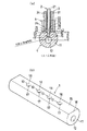
コモンレール1には、図1に示すごとく燃料配管2が連結されている。燃料配管2は、コモンレール1内に蓄圧された高圧燃料を各気筒に分配供給するための配管である。この燃料配管2とは別に、コモンレール1には燃料供給ポンプから加圧圧送される高圧燃料をコモンレール1内へ供給するための燃料配管(図示せず)が連結されている。
コモンレール1と燃料配管2との連結方法の概略は次のとおりである。ボルト3がスリーブ4と締結することにより、燃料配管2がボルト3によってコモンレール1の方に押圧される。これにより、コモンレール1と燃料配管2とが連結される。
【0014】
なお、図1においてコモンレール1の左右両端は、六角穴付きのネジにより密閉されているが、車両への搭載時には燃料圧力センサ(図示せず)やプレッシャリミッタ(図示せず)などが締め付け固定される。燃料圧力センサは、コモンレール1内の燃料圧力(コモンレール圧力)に対応した圧力信号を出力する。この出力値に基づいて燃料噴射タイミングなどが算出される。プレッシャリミッタは、コモンレール圧力が限界設定圧力を超えないように、コモンレール内の高圧燃料を逃すものである。また、プレッシャリミッタの代わりに、コモンレール圧力を高圧から低圧へ降圧させるための減圧調整弁を組み付けることもできる。
【0015】
本実施形態のコモンレール1は、周壁部11、蓄圧室12、連通孔13および組付部14などを有する。周壁部11は、蓄圧室12を囲う部分円筒形状の壁部であり、断面が真円形状の丸棒材を加工することによって形成されている。この丸棒材は、例えば低炭素鋼等の低硬度材料を鍛造成形またはプレス成形することにより製作されている。
【0016】
蓄圧室12は、丸棒材を、その長手方向と平行な軸方向に貫通するように形成されている。この蓄圧室12に、燃料供給ポンプによって加圧圧送された燃料が流入する。そして、蓄圧室12内で蓄圧された高圧燃料が各気筒のインジェクタへ分配供給される。
蓄圧室12は、図2(a)に示すごとく丸棒材の軸心(コモンレール1の軸心)、すなわち、丸棒材の断面形状をなす円の中心から偏心した位置に形成されている。蓄圧室12の形成には、ドリル等の切削工具が用いられる。この切削工具の回転切削運動とその回転の中心線の方向への直線送り運動との組み合わせにより、蓄圧室12が形成される。
【0017】
連通孔13は、蓄圧室12と後記する燃料配管2の燃料流路21とを連通させる。連通孔13は、図2(b)に示すごとく平坦面15から略直角に蓄圧室12へ向かって形成され、蓄圧室12と略直角に交差する。連通孔13の形成は、ドリル等の切削工具の回転切削運動とその回転の中心線の方向への直線送り運動との組み合わせにより行われる。また、プレスによる孔開けなどによっても、連通孔13の形成が可能である。
【0018】
平坦面15は、蓄圧室12をコモンレール1の軸心から偏心させることにより、周壁部11において肉厚となった肉厚部16の外周に設けられている。平坦面15は、コモンレール1の軸心および蓄圧室12の軸心を垂直に結ぶ直線と直交する平面である。この平面は、コモンレール1の長手方向に一端側から他端側に向かって、肉厚部16の外周を一様に切り取って平坦に加工したものである。
【0019】
連通孔13は、図2(a)に示すごとく、蓄圧室12から平坦面15に向かい孔径が同一である円筒部分と、平坦面15に向かい孔径が円錐状に拡大する円錐部分とからなる。円筒部分は、蓄圧室12で蓄圧された高圧燃料が、蓄圧室12から燃料配管2の燃料流路21に向かって流れる燃料流路17をなす。円錐部分は、燃料配管2とコモンレール1とが連結されたときに、後記する燃料配管2の連結頭部22が液密的に嵌合される受圧座面18をなす。
なお、組付部14は、車両への搭載時にネジまたはボルトなどを挿通して締め付け、コモンレール1を所定の場所に固定するために用いられる。
【0020】
燃料配管2は、図2(a)に示すごとく内部に燃料流路21を有し、一端部がコモンレール1の受圧座面18に嵌合される連結頭部22をなし、他端部は各気筒のインジェクタの配管継手部(図示せず)に連結されている。
燃料流路21は、インジェクタ内に形成される燃料通路、油溜り、圧力制御室などに燃料を流入させるための配管であり、蓄圧室12で蓄圧された高圧燃料が流れる。また、燃料流路21は、連結頭部22の内部にも形成され、燃料配管2の一端側先端、すなわち連結頭部22の先端が開口して開口部23を形成している。この開口部23は、燃料配管2とコモンレール1とが連結されたときには、連通孔13の燃料流路17に臨んでいる。
【0021】
連結頭部22は、燃料配管2のその他の部分よりも外径が大きい鍔状をなし、かつ連結頭部22の先端に向かい外径が縮小する円錐状をなしている。連結頭部22の上部端面、すなわち、燃料配管2の他の部分よりも外径が大きく鍔をなす略円環状の面は、燃料配管2とコモンレール1とが連結されたときに、後記するボルト3の先端により下方に押圧される受圧座面24をなす(便宜上、コモンレール1側を下方、燃料配管2側を上方とする)。一方、連結頭部22の下部の円錐状の面は、燃料配管2とコモンレール1とが連結されたときに、コモンレール1の受圧座面18に液密的に嵌合されるシール面25をなす。
【0022】
ボルト3は、コモンレール1に燃料配管2をつなぎ合わせる配管継手である。ボルト3は、通常のボルトと同様に、スパナなどをあてがい回転させて締め付ける六角頭のボルト頭部31と、オネジ32が設けられたボルト軸部33とからなる。ボルト3の内部には、ボルト頭部31およびボルト軸部33の軸方向に、ボルト頭部31とボルト軸部33を貫通して、燃料配管2が挿通される挿通孔34が設けられている。オネジ32は、コモンレール1に燃料配管2をつなぎ合わせる際に、スリーブ4のメネジ41に締結される締結部である。ボルト3の先端側、すなわちボルト軸部33の先端側の端面には、燃料配管2とコモンレール1とを連結する際に、燃料配管2の受圧座面24を下方に押圧する押圧部35が形成されている。
【0023】
スリーブ4は、ボルト3と締結されることにより、燃料配管2の連結頭部22を保持するとともに、燃料配管2の燃料流路21とコモンレール1の連通孔13とを連結する円筒状のコネクタである。スリーブ4は、内周面にメネジ41が設けられている。メネジ41は、コモンレール1に燃料配管2をつなぎ合わせる際に、ボルト3のオネジ32が締結する被締結部である。スリーブ4の一端側の端面には、コモンレール1の平坦面15に接合される接合面42が形成されている。
【0024】
接合面42は、円環状の平面であり、連通孔13の平坦面15側の開口部を囲うように、平坦面15に接合される。そして、ボルト3をスリーブ4に締結してコモンレール1に燃料配管2をつなぎ合わせたときに、連通孔13と燃料流路21とが連通できるように位置決めされて接合される。コモンレール1の平坦面15とスリーブ4の接合面42との接合は、通常のアーク溶接により行われる。具体的には、溶接棒と母材(コモンレール1の平坦面15またはスリーブ4の接合面42)の間に電圧をかけてアークを発生させ、アークの熱により溶接棒を溶かして母材の一部と融合させて溶接金属とし、母材同士、すなわちコモンレール1の平坦面15とスリーブ4の接合面42とを接合させる。
【0025】
〔第1実施形態の連結方法〕
次に、コモンレール1と燃料配管2との連結方法を説明する。燃料配管2は、予め、ボルト3の挿通孔34に、連結頭部22の受圧座面24と押圧部35とが接触できる方向に挿通されている。
まず、コモンレール1とスリーブ4との接合位置を決め、コモンレール1の平坦面15とスリーブ4の接合面42とを、アーク溶接により接合する。次に、燃料配管2の連結頭部22のシール面25をコモンレール1の受圧座面18に嵌合させる。
【0026】
そして、予め燃料配管2を挿通させておいたボルト3のオネジ32とスリーブ4のメネジ41とを締結する。締結は、スパナなどの工具をボルト頭部31にあてがい、ボルト3を回転させることにより行う。これにより、ボルト3の押圧部35は、スリーブ4内を下方に向かって変位し連結頭部22の受圧座面24に接触する。さらにボルト3を回転させると、押圧部35が受圧座面24を押圧し、これに伴い連結頭部22のシール面25がコモンレール1の受圧座面18に圧接される。これにより、連結頭部22が液密的に受圧座面18に嵌合される。
【0027】
〔第1実施形態の作用〕
燃料供給ポンプより加圧圧送された高圧燃料は、図示しない燃料配管によりコモンレール1の蓄圧室12に流入し、蓄圧室12内で蓄圧される。ここで、例えば#1気筒のインジェクタから#1気筒内への燃料噴射が開始されると、蓄圧室12内に蓄圧されていた高圧燃料は、#1気筒に対応した連通孔13を経て、燃料配管2の燃料流路21に流入する。そして、燃料流路21を経て#1気筒のインジェクタの配管継手部から、インジェクタ内に形成される燃料通路、油溜り、圧力制御室などに高圧燃料が供給される。その他の気筒のインジェクタについても、同様にして高圧燃料が供給される。
【0028】
〔第1実施形態の効果〕
以上のように、コモンレール1と燃料配管2とをボルト3およびスリーブ4により連結する蓄圧式燃料噴射装置において、コモンレール1の蓄圧室12をコモンレール1の軸心から偏心した位置に設け、蓄圧室12の偏心により肉厚となった肉厚部16の外周にスリーブ4の先端部が接合する平坦面15を設ける。
これによると、肉厚部16によって、連通孔13と蓄圧室12との交差部における強度を確保でき、かつ燃料配管2の連結頭部22が嵌合される受圧座面18の加工代を確保できる。また、肉厚部16の外周に設けた平坦面15によって、スリーブ4とコモンレール1との接合面積を確保できる。それによって、コモンレール1の体格を従来と同等したままで、すなわち、コモンレール1の外径を大きくすることなくスリーブ4とコモンレール1との接合面積を確保できる。さらに接合面を深く加工する必要がないので加工コストを安価にできる。
【0029】
また、スリーブ4は円筒状に形成されており、このスリーブ4の一端側の端面に、コモンレール1の平坦面15に接合される接合面42を設けている。
それによって、燃料配管2とコモンレール1との嵌合部分をスリーブ4で囲うようにスリーブ4とコモンレール1とを接合することができる。
【0030】
さらに、コモンレール1に燃料配管2を連結するために、スリーブ4とは別体で、燃料配管2を挿通させる挿通孔34を有するボルト3を用いている。ボルト3は、挿通孔34に燃料配管2を挿通して保持し、燃料配管2の一端部に設けられた鍔状の連結頭部22をボルト3の先端に設けられた押圧部35で押圧することができる。
これによると、ボルト3をスリーブ4に締結させることで、連結頭部22が押圧部35によりコモンレール1の方に押圧されるため、コモンレール1に燃料配管2を連結させることができる。このため、コモンレール1に燃料配管2を連結させる手段として、オネジ32とメネジ41との締結という簡単な方法を用いることができる。
【0031】
また、コモンレール1は、燃料配管2の連結頭部22が液密的に嵌合する受圧座面18を有している。
それによって、燃料配管2の一端部とコモンレール1の連通孔13との連結部における燃料漏れを防止することができる。
【0032】
〔第2実施形態〕
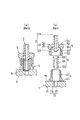
第2実施形態では、図3に示すごとくスリーブナット5を配管継手として用いる。そして、中間連結部材6を介してコモンレール1と燃料配管2とが連結されている。
第2実施形態では、スリーブ4は、内周面にメネジ41が設けられる代わりに、外周面にオネジ43が設けられている。このオネジ43は、コモンレール1と燃料配管2とが連結される際に、スリーブナット5のメネジ51が締結する被締結部である。
【0033】
スリーブナット5は、通常の六角ナットと同様にスパナなどをあてがい回転させて締め付ける六角柱状の頭部52と、内周面にメネジ51が設けられたスリーブ部53とからなる。メネジ51は、コモンレール1と燃料配管2とを連結する際に、スリーブ4のオネジ43が締結される締結部である。そして、頭部52にスパナなどをあてがい回転させて締め付けることにより、スリーブナット5のメネジ51とスリーブ4のオネジ43とを締結する。頭部52の内部には、スリーブナット5の軸方向に頭部52を貫通して、燃料配管2が挿通される挿通孔54が設けられている。そして、燃料配管2は、予め、この挿通孔54に、頭部52のスリーブ側内面55で連結頭部22の受圧座面24を押圧できる方向に挿通されている。
【0034】
中間連結部材6は、外径がスリーブ4の内径よりも小さい円筒部材である。そして、中間連結部材6は、コモンレール1と燃料配管2とが連結される際に、スリーブ4の中空部に内蔵される。
中間連結部材6の中空部は高圧燃料が流れる燃料流路61をなす。そして、中間連結部材6の一端側は、略半球面形状のシール面62をなし、燃料流路61が開口している。このシール面62は、コモンレール1と燃料配管2とを連結する際、コモンレール1の受圧座面18に圧接される。これにより、中間連結部材6の一端側が液密的に受圧座面18に嵌合される。中間連結部材6の他端側は、燃料流路61の孔径が開口部に向かって円錐状に拡大する受圧座面63をなす。この受圧座面63には、コモンレール1と燃料配管2とを連結する際、燃料配管2の連結頭部22のシール面25が圧接される。これにより、中間連結部材6の他端側の受圧座面63に、連結頭部22が液密的に嵌合される。
これにより、第1実施形態と同様の効果を得ることができる。
【0035】
〔第3実施形態〕
第3実施形態では、図4に示すごとくスリーブナット5を配管継手として用いる。このスリーブナット5が中間押圧部材7を介して燃料配管2を押圧することにより、コモンレール1と燃料配管2とが連結されている。
中間押圧部材7は、鍔状のフランジ部71と円筒状のスリーブ部72とからなる。中間押圧部材7のフランジ部71側の端部は、コモンレール1と燃料配管2とを連結する際、スリーブナット5のスリーブ側内面55により押圧される受圧座面73をなす。一方、スリーブ部72側の端部は、コモンレール1と燃料配管2とを連結する際、燃料配管2の連結頭部22の受圧座面24を押圧する押圧部74をなす。
【0036】
フランジ部71は、その外径がスリーブナット5のスリーブ側内面55の内径よりも小さい。そして、フランジ部71は、予め、スリーブ側内面55が受圧座面73を押圧することができるように、スリーブナット5のスリーブ部53の内側に内蔵されている。また、中間押圧部材7には、軸方向にフランジ部71およびスリーブ部72を貫通して、燃料配管2が挿通される円柱状の中空部が形成されている。そして、燃料配管2は、予め、中間押圧部材7の押圧部74で連結頭部22の受圧座面24を押圧できるように、この中空部に挿通されている。
これにより、第1実施形態と同様の効果を得ることができる。
【0037】
〔他の実施形態〕
本実施形態では、メネジとオネジとを締結させるねじ込み式を採用したが、スリーブ4の外周面にフランジを設け、燃料配管2または燃料配管2と別体の配管継手に設けられたフランジとパッキンなどを介して突合せボルトおよびナットで締結するフランジ式を採用してもよく、スリーブ4のコモンレール1との接合面とは反対側端部を円錐状に広げて円錐部とし、燃料配管2または燃料配管2と別体の配管継手に設けられたコーン部とフレアとで、円錐部を挟み込んで締め付けるフレア式でもよい。なおフレア式の場合、締め付け方法としては、燃料配管2または燃料配管2と別体の配管継手にオネジを設け、フレアの内周部にメネジを設けたねじ込み式でもよく、燃料配管2または燃料配管2と別体の配管継手、およびフレアの外周部にフランジを設け、パッキンなどを介してフランジ同士を突合せボルトおよびナットで締結するフランジ式でもよい。
【0038】
第1実施形態では、燃料配管2とは別体のボルト3を用い、ボルト3のオネジ32をスリーブ4のメネジ41に締結させているが、燃料配管2自身にオネジ(締結部)を設けて、メネジ41(被締結部)と締結させてもよい。
第2実施形態および第3実施形態では、コモンレール1と燃料配管2とを液密的に連結させるため、中間連結部材6または中間押圧部材7を用いたが、このような中間部材を用いず、燃料配管2の外周部に連結頭部22とは別の鍔状のフランジ部を設け、スリーブナット5のスリーブ側内面55がこのフランジ部をコモンレール1の方向に押圧するようにしてもよい。
【0039】
本実施形態では、コモンレール1は断面が真円形状の丸棒材を加工することによって形成されているが、断面が楕円形状または長円形状の棒材を加工して、部分楕円または部分長円の筒状のコモンレールを成形してもよい。
本実施形態では、ボルト3のボルト頭部31およびスリーブナット5の頭部52は六角頭であったが、四角頭、丸頭、ナベ頭、平頭、丸平頭、サラ頭、または丸サラ頭などであってもよい。
本実施形態では、平坦面15は、肉厚部16の外周を一様に切り取って平坦に加工したものであるが、部分的に切り取ったものであってもよい。例えば、スリーブ4の接合面42が接合される部分のみを、部分的に切り取って平坦に加工してもよい。
【0040】
第1実施形態および第3実施形態では、円錐状の連結頭部22が連通孔13の円錐部分に設けられた受圧座面18に液密的に嵌合されているが、連結頭部22を鍔状のフランジ部とし、このフランジ部のコモンレール側端面をシール面25としてコモンレール1の平坦面15に液密的に密着させてもよい。この場合には、フランジ部のコモンレール側端面と平坦面15との間にパッキンを介挿させてもよく、コモンレール1の挿通孔13に円錐部分を設けなくてもよい。
【0041】
第2実施形態では、円錐状の連結頭部22が中間連結部材6の円錐状の受圧座面63に液密的に嵌合されているが、連結頭部22を鍔状のフランジ部とし、かつ中間連結部材6の燃料配管側端部を平面状に加工し、連結頭部22のフランジ部と中間連結部材6の燃料配管側端部とを液密的に密着させてもよい。この場合には、連結頭部22のフランジ部と中間連結部材6の燃料配管側端部との間にパッキンを介挿させてもよい。あるいは、中間連結部材6の燃料配管側端部を鍔状のフランジ部とし、かつ連結頭部22をなくして燃料配管2の中間連結部材側端部を平面状に加工し、中間連結部材6のフランジ部と燃料配管2の中間連結部材側端部とを液密的に密着させてもよい。この場合には、中間連結部材6のフランジ部と燃料配管2の中間連結部材側端部との間にパッキンを介挿させてもよい。
【0042】
さらに、第2実施形態では、中間連結部材6の略半球面形状のシール面62が受圧座面18に液密的に嵌合されているが、中間連結部材6のコモンレール側端部を鍔状のフランジ部とし、このフランジ部とコモンレール1の平坦面15とを液密的に密着させてもよい。この場合には、中間連結部材6のフランジ部と平坦面15との間にパッキンを介挿させてもよい。
【0043】
本実施形態では、スリーブ4の接合面42とコモンレール1の平坦面15との接合にアーク溶接を用いたが、平坦面15の被接合部分または接合面42を融点近くに加熱して圧接する高温圧接や、母材(コモンレール1の平坦面15またはスリーブ4の接合面42)よりも融点の低い金属を溶融添加して接合するろう付けやはんだ付けなどを用いてもよい。
【図面の簡単な説明】
【図1】第1実施形態における燃料配管のコモンレールへの連結状態を示す断面図である。
【図2】(a)は図1のA−A断面図で、(b)はコモンレールの概略を示す斜視図である。
【図3】第2実施形態における燃料配管のコモンレールへの連結状態を示す断面図である。
【図4】第3実施形態における燃料配管のコモンレールへの連結状態を示す断面図である。
【図5】ボルトとスリーブの締結によるコモンレールと燃料配管の連結を示す断面図である(従来技術)。
【符号の説明】
1 コモンレール
11 周壁部
12 蓄圧室
13 連通孔
15 平坦面
16 肉厚部
17 燃料流路
18 受圧座面
2 燃料配管
21 燃料流路
22 連結頭部
24 受圧座面
25 シール面
3 ボルト(配管継手)
31 ボルト頭部
32 オネジ(締結部)
33 ボルト軸部
34 挿通孔
35 押圧部
4 スリーブ(コネクタ)
41 メネジ(被締結部)
42 接合面
43 オネジ(被締結部)
5 スリーブナット
51 メネジ(締結部)
54 挿通孔
55 スリーブ側内面
6 中間連結部材
61 燃料流路
62 シール面
63 受圧座面
7 中間押圧部材
73 受圧座面
74 押圧部[0001]
TECHNICAL FIELD OF THE INVENTION
The present invention relates to a pressure-accumulation type fuel injection device for injecting high-pressure fuel accumulated in a common rail into a cylinder of an internal combustion engine via a fuel injection valve, and particularly to a connection structure for connecting a fuel pipe and a common rail. Get involved.
[0002]
[Prior art]
Conventionally, in a pressure accumulating fuel injection device known as a fuel injection device for a diesel engine, fuel is pressurized and fed by a fuel supply pump, high-pressure fuel discharged by the fuel supply pump is stored in a common rail, and the fuel is supplied to the common rail. The high-pressure fuel stored in the cylinder is distributed and supplied to a plurality of electromagnetic fuel injection valves (injectors) connected to a downstream end of a high-pressure pipe branched from a common rail, and the high-pressure fuel is injected into each cylinder of the engine from the injector of each cylinder. It is configured to supply by injection.
[0003]
Here, the connecting means (connector) for connecting the fuel rail connected to the fuel supply pump or the injector to the common rail includes a type integrally formed with the common rail and a type separately formed. However, those molded integrally with the common rail are difficult to cut, resulting in high costs. Therefore, a method has been proposed in which a connector formed separately from the common rail is joined to the common rail (for example, see
[0004]
[Patent Document 1]
JP-A-10-259772 (pages 3-5, FIG. 2)
[Patent Document 2]
JP 2001-82663 A (
[0005]
[Problems to be solved by the invention]
When the common rail and the connector are separate bodies, the
[0006]
In order to prevent the common rail 101 from increasing in size, as shown in FIG. 5B, the
[0007]
[Object of the invention]
An object of the present invention is to provide a common rail that can secure a joint area with a connector and reduce processing costs without increasing the size of the common rail.
[0008]
[Means for Solving the Problems]
[Means of claim 1]
According to a first aspect of the present invention, in a pressure accumulating type fuel injection device for connecting a fuel pipe and a common rail by a connector, a pressure accumulating chamber of the common rail is provided at a position eccentric from an axis of the common rail, and a wall thickness is reduced by eccentricity of the pressure accumulating chamber. A flat surface is provided on the outer periphery of the thickened portion to which the distal end of the connector is joined.
According to this, the strength at the intersection between the communication hole and the pressure accumulation chamber can be secured by the thick portion, and the machining allowance for the pressure receiving seat surface can be secured. In addition, the flat surface provided on the outer periphery of the thick portion ensures a sufficient joint area between the connector and the common rail. As a result, the physique of the common rail can be made equal to that of the conventional one, and the processing cost can be reduced because it is not necessary to deeply process the joint surface.
[0009]
[Means of Claim 2]
The invention according to
According to this, an annular joint surface can be provided on the end face on one end side of the sleeve. Thereby, the sleeve and the common rail can be joined so that the fitting portion between the fuel pipe and the common rail is surrounded by the sleeve.
[0010]
[Means of Claim 3]
According to a third aspect of the present invention, a sleeve (connector) is provided with a fastened portion to be fastened to a fastened portion of the fuel pipe, and the fastened portion is fastened to the fastened portion, so that one end of the fuel pipe is connected to the fastened portion. It is characterized in that it is connected to a communication hole of a common rail.
Thus, one end of the fuel pipe and the communication hole of the common rail can be connected by a simple method such as fastening of a male screw and a female screw.
[0011]
[Means of Claim 4]
The invention according to
Thus, one end of the fuel pipe and the communication hole of the common rail can be connected by a pipe joint separate from the fuel pipe, so that there is no need to provide a fastening portion in the fuel pipe.
[0012]
BEST MODE FOR CARRYING OUT THE INVENTION
[Configuration of First Embodiment]
A first embodiment of the present invention will be described with reference to FIGS. The pressure-accumulation fuel injection device of the first embodiment accumulates high-pressure fuel pressurized and fed by a fuel supply pump (not shown) in a
[0013]
A
An outline of a method of connecting the
[0014]
In FIG. 1, the left and right ends of the
[0015]
The
[0016]
The
As shown in FIG. 2A, the
[0017]
The
[0018]
The
[0019]
As shown in FIG. 2A, the
The mounting
[0020]
The
The
[0021]
The
[0022]
The
[0023]
The
[0024]
The
[0025]
[Connection method of the first embodiment]
Next, a method of connecting the
First, the joint position between the
[0026]
Then, the
[0027]
[Operation of First Embodiment]
The high-pressure fuel pressurized and fed from the fuel supply pump flows into the
[0028]
[Effects of First Embodiment]
As described above, in the pressure-accumulation type fuel injection device in which the
According to this, the strength at the intersection of the
[0029]
The
Thereby, the
[0030]
Further, in order to connect the
According to this, when the
[0031]
Further, the
Thereby, it is possible to prevent the fuel from leaking at the connection between the one end of the
[0032]
[Second embodiment]
In the second embodiment, a
In the second embodiment, the
[0033]
The
[0034]
The intermediate connecting
The hollow portion of the intermediate connecting
Thereby, the same effect as in the first embodiment can be obtained.
[0035]
[Third embodiment]
In the third embodiment, a
The intermediate
[0036]
The outer diameter of the
Thereby, the same effect as in the first embodiment can be obtained.
[0037]
[Other embodiments]
In the present embodiment, the screw-in type for fastening the female screw and the male screw is adopted. However, a flange is provided on the outer peripheral surface of the
[0038]
In the first embodiment, the
In the second and third embodiments, the intermediate connecting
[0039]
In the present embodiment, the
In the present embodiment, the
In the present embodiment, the
[0040]
In the first embodiment and the third embodiment, the
[0041]
In the second embodiment, the
[0042]
Further, in the second embodiment, the substantially
[0043]
In the present embodiment, arc welding is used to join the
[Brief description of the drawings]
FIG. 1 is a cross-sectional view showing a connection state of a fuel pipe to a common rail according to a first embodiment.
2A is a sectional view taken along line AA of FIG. 1, and FIG. 2B is a perspective view schematically showing a common rail.
FIG. 3 is a cross-sectional view showing a connection state of a fuel pipe to a common rail according to a second embodiment.
FIG. 4 is a cross-sectional view illustrating a connection state of a fuel pipe to a common rail according to a third embodiment.
FIG. 5 is a cross-sectional view showing connection between a common rail and a fuel pipe by fastening a bolt and a sleeve (prior art).
[Explanation of symbols]
1 common rail
11 Perimeter wall
12 accumulator
13 communication hole
15 Flat surface
16 Thick part
17 Fuel flow path
18 Pressure receiving surface
2 Fuel piping
21 Fuel flow path
22 Connecting head
24 Pressure bearing surface
25 Seal surface
3 bolts (piping joint)
31 bolt head
32 male screw (fastening part)
33 bolt shaft
34 insertion hole
35 Pressing part
4 Sleeve (connector)
41 Female thread (fastened part)
42 Joining surface
43 Male thread (fastened part)
5 Sleeve nut
51 Female thread (fastening part)
54 insertion hole
55 Sleeve side inner surface
6 Intermediate connecting members
61 Fuel flow path
62 Seal surface
63 Pressure receiving surface
7 Intermediate pressing member
73 Pressure bearing surface
74 Pressing part
Claims (4)
軸方向に貫通するように設けられた蓄圧室、およびこの蓄圧室と前記燃料流路とを連通させる連通孔を有する断面形状が略部分円筒形状のコモンレールと、
このコモンレールとは別体であり、前記燃料配管の一端部を保持すると共に、前記コモンレールの外周面に接合されて、前記燃料配管の一端部と前記コモンレールの連通孔とを連結するコネクタとを備えた蓄圧式燃料噴射装置において、
前記蓄圧室は、前記コモンレールの軸心から偏心した位置に設けられ、
前記コモンレールは、前記コモンレールの軸心から前記蓄圧室を偏心させることにより肉厚となった肉厚部の外周に、前記コネクタの先端部が接合する平坦面を有することを特徴とする蓄圧式燃料噴射装置。A fuel pipe having a fuel passage therein;
A pressure accumulation chamber provided so as to penetrate in the axial direction, and a common rail having a substantially partially cylindrical cross section having a communication hole for communicating the pressure accumulation chamber with the fuel flow path,
The common rail is separate from the common rail, and includes a connector that holds one end of the fuel pipe, is joined to an outer peripheral surface of the common rail, and connects one end of the fuel pipe and a communication hole of the common rail. Pressure accumulation type fuel injection device,
The accumulator is provided at a position eccentric from the axis of the common rail,
The pressure-accumulating fuel, characterized in that the common rail has a flat surface to which the distal end of the connector is joined on the outer periphery of a thick portion formed by eccentricizing the pressure accumulating chamber from the axis of the common rail. Injection device.
前記コネクタは、筒状のスリーブであり、
このスリーブの一端側の端面に、前記平坦面に接合される接合面が設けられていることを特徴とする蓄圧式燃料噴射装置。The pressure accumulating fuel injection device according to claim 1,
The connector is a tubular sleeve,
A pressure accumulating fuel injection device, wherein a joining surface joined to the flat surface is provided on an end surface on one end side of the sleeve.
前記スリーブに、前記燃料配管が有する締結部と締結される被締結部が設けられ、
前記締結部を前記被締結部に締結することにより、前記燃料配管の一端部と前記コモンレールの連通孔とを連結することを特徴とする蓄圧式燃料噴射装置。The pressure accumulating fuel injection device according to claim 2,
The sleeve is provided with a fastened portion to be fastened to a fastening portion of the fuel pipe,
An accumulator-type fuel injection device, characterized in that one end of the fuel pipe is connected to a communication hole of the common rail by fastening the fastening portion to the fastened portion.
前記締結部は、前記燃料配管とは別体の配管継手に設けられていることを特徴とする蓄圧式燃料噴射装置。The pressure accumulating fuel injection device according to claim 3,
The pressure accumulating fuel injection device, wherein the fastening portion is provided in a pipe joint separate from the fuel pipe.
Priority Applications (4)
| Application Number | Priority Date | Filing Date | Title |
|---|---|---|---|
| JP2003030906A JP2004239212A (en) | 2003-02-07 | 2003-02-07 | Accumulator fuel injection device |
| US10/610,693 US6886537B2 (en) | 2002-07-04 | 2003-07-02 | Accumulation type fuel injection system for engine |
| EP03015177A EP1378658B1 (en) | 2002-07-04 | 2003-07-03 | Accumulation type fuel injection system for engine |
| DE60324990T DE60324990D1 (en) | 2002-07-04 | 2003-07-03 | Storage fuel injection system for internal combustion engines |
Applications Claiming Priority (1)
| Application Number | Priority Date | Filing Date | Title |
|---|---|---|---|
| JP2003030906A JP2004239212A (en) | 2003-02-07 | 2003-02-07 | Accumulator fuel injection device |
Publications (1)
| Publication Number | Publication Date |
|---|---|
| JP2004239212A true JP2004239212A (en) | 2004-08-26 |
Family
ID=32957661
Family Applications (1)
| Application Number | Title | Priority Date | Filing Date |
|---|---|---|---|
| JP2003030906A Pending JP2004239212A (en) | 2002-07-04 | 2003-02-07 | Accumulator fuel injection device |
Country Status (1)
| Country | Link |
|---|---|
| JP (1) | JP2004239212A (en) |
Cited By (4)
| Publication number | Priority date | Publication date | Assignee | Title |
|---|---|---|---|---|
| JP2006218519A (en) * | 2005-02-10 | 2006-08-24 | Denso Corp | Welded structure and common rail |
| JP2012513562A (en) * | 2008-12-23 | 2012-06-14 | デルファイ・テクノロジーズ・ホールディング・エス.アー.エール.エル. | Fuel injection system |
| WO2019181166A1 (en) * | 2018-03-23 | 2019-09-26 | 三桜工業株式会社 | Manufacturing method for fuel rail, and fuel rail |
| EP3599372A1 (en) * | 2018-07-24 | 2020-01-29 | Continental Automotive GmbH | Fuel rail for a fuel injection system and method of manufacturing such a fuel rail |
-
2003
- 2003-02-07 JP JP2003030906A patent/JP2004239212A/en active Pending
Cited By (5)
| Publication number | Priority date | Publication date | Assignee | Title |
|---|---|---|---|---|
| JP2006218519A (en) * | 2005-02-10 | 2006-08-24 | Denso Corp | Welded structure and common rail |
| JP2012513562A (en) * | 2008-12-23 | 2012-06-14 | デルファイ・テクノロジーズ・ホールディング・エス.アー.エール.エル. | Fuel injection system |
| US8720418B2 (en) | 2008-12-23 | 2014-05-13 | Delphi International Operations Luxembourg, S.A.R.L. | Fuel injection system |
| WO2019181166A1 (en) * | 2018-03-23 | 2019-09-26 | 三桜工業株式会社 | Manufacturing method for fuel rail, and fuel rail |
| EP3599372A1 (en) * | 2018-07-24 | 2020-01-29 | Continental Automotive GmbH | Fuel rail for a fuel injection system and method of manufacturing such a fuel rail |
Similar Documents
| Publication | Publication Date | Title |
|---|---|---|
| EP1378658B1 (en) | Accumulation type fuel injection system for engine | |
| US5775302A (en) | Fuel distributor pipe | |
| EP1467084B1 (en) | Pipe joint structure and method of assembling the same | |
| JP4518459B2 (en) | Fuel high pressure accumulator | |
| JP4075838B2 (en) | Piping joint device | |
| CN100460662C (en) | Common rail | |
| JP2004211637A (en) | High pressure fuel accumulator | |
| EP2093413A1 (en) | Coupling device | |
| US7246601B2 (en) | Common rail | |
| JP5768635B2 (en) | Installation structure of fuel distribution pipe | |
| US7066148B2 (en) | Common rail having skew delivery ports | |
| JP2006233866A (en) | Common rail | |
| GB2349190A (en) | A method of manufacturing a common rail | |
| US20220307454A1 (en) | Fitting for a Fluid Delivery System | |
| JP2005508478A (en) | Method for fabricating a fuel accumulator line with a preloaded connection piece | |
| JP2005009394A (en) | Connection structure for common rail branch connector | |
| JP2004239212A (en) | Accumulator fuel injection device | |
| JP4020503B2 (en) | Common rail injection pipe | |
| JP2001082663A (en) | Connecting structure of branch connecting body for common rail | |
| JP3768043B2 (en) | Connection structure of branch connection for common rail | |
| JP2004036536A (en) | Accumulator fuel injection device | |
| KR20170027816A (en) | Terminal sealing structure for fuel rail for gasoline direct-injection engine | |
| JP5190340B2 (en) | Common rail | |
| JP2004108269A (en) | Accumulator fuel injection device | |
| JPH10176783A (en) | Common rail |
Legal Events
| Date | Code | Title | Description |
|---|---|---|---|
| A621 | Written request for application examination |
Free format text: JAPANESE INTERMEDIATE CODE: A621 Effective date: 20050421 |
|
| A131 | Notification of reasons for refusal |
Free format text: JAPANESE INTERMEDIATE CODE: A131 Effective date: 20061205 |
|
| A977 | Report on retrieval |
Free format text: JAPANESE INTERMEDIATE CODE: A971007 Effective date: 20061206 |
|
| A02 | Decision of refusal |
Free format text: JAPANESE INTERMEDIATE CODE: A02 Effective date: 20070403 |