【0001】
【発明の属する技術分野】
本発明は、下水道施設や農業用水路施設等の水路の水量調整を行ったり、堰止めたりする角落し構造に関するものである。
【0002】
【従来の技術】
下水道施設、農業用水路施設及び栽培漁業施設等の水路を堰止めたり、水量調整を行うために、水路の必要とする箇所に複数の角落しを所要高さに積み重ねる角落し構造を設置している。
【0003】
従来の角落し構造としては、例えば、図5にも示すように、水路の相対する壁面に設けたガイド溝bに、複数の角落しaを水平状態となして両端を挿入するようにして下から順次積み重ねて所定高さとなし、それらの角落しaを補強枠体cで保持するようにして、遮水壁を形成するような構造となっている(特許文献1参照)。
【0004】
しかしながら、このような従来の角落し構造では、水量調整を行う場合には、積み重ねた複数の角落しaの上段側の数段のみを取り外すようにして調整することとなるので、水路の底部付近の処理水は常に滞留してその流れをコントロールすることができず、処理効率を改善することができないという問題点がある。
【0005】
【特許文献1】
特開平11−166225号公報
【0006】
【発明が解決しようとする課題】
本発明は、上記のような従来の問題点を解消し、水路の底部付近の処理水であっても、所定の開口率にてその流れをコントロールすることができて、処理効率の向上した角落し構造を提供することを目的としてなされたものである。
【0007】
【課題を解決するための手段】
本願の請求項1に記載の発明は、水路を堰止める角落し構造であって、該水路の堰止め部分の水路幅方向の相対する側壁及び底壁にガイド溝が設けられ、該ガイド溝に、水路幅方向に沿って複数の直方体からなる角落しがその長手方向を直立するようにして並設され、それらの角落しの上端部が横架材に係止自在とされている角落し構造である。
【0008】
本願の請求項2に記載の発明は、前記横架材が水路躯体に固定自在とされている請求項1に記載の角落し構造である。
【0009】
本願の請求項3に記載の発明は、水路を堰止める角落し構造であって、該水路の堰止め部分の水路幅方向の相対する側壁及び底壁にガイド溝が設けられ、該ガイド溝に、上方が開放する略コ字状の枠体が配設固定自在とされ、該枠体に水路幅方向に沿って複数の直方体からなる角落しがその長手方向を直立するようにして並設され、それらの角落しの上端部が前記枠体に係止自在とされている角落し構造である。
【0010】
本願の請求項4に記載の発明は、前記枠体内で少なくとも一側部となる角落しと前記枠体との間にくさびが打込み自在とされている請求項3に記載の角落し構造である。
【0011】
【作用】
本願の請求項1に係る発明の角落し構造は、水路を堰止める角落し構造であって、該水路の堰止め部分の水路幅方向の相対する側壁及び底壁にガイド溝が設けられ、該ガイド溝に、水路幅方向に沿って複数の直方体からなる角落しがその長手方向を直立するようにして並設され、それらの角落しの上端部が横架材に係止自在とされていることにより、ガイド溝にその幅方向に沿って複数の角落しを長手方向を直立するように並設して所定高さとなし、それらの角落しを横架材に係止するようにして水路を堰止めることができ、また、水路を堰止めた状態から、流下させる処理水の水量調整を行うときには、流下させる処理水の水量に応じて、各角落しを、横架材との浮上防止ピンを外し、必要な枚数だけ一側方から順番に上方に引き抜いて、所定の開口率にて水路の底部付近の処理水の流れをコントロールすることができるので、処理効率を向上させることができる。
【0012】
本願の請求項2に係る発明の角落し構造は、前記横架材が水路躯体に固定自在とされていることにより、各角落しが浮き上がらないように水路を堰止めることができる。
【0013】
本願の請求項3に係る発明の角落し構造は、水路を堰止める角落し構造であって、該水路の堰止め部分の水路幅方向の相対する側壁及び底壁にガイド溝が設けられ、該ガイド溝に、上方が開放する略コ字状の枠体が配設固定自在とされ、該枠体に水路幅方向に沿って複数の直方体からなる角落しがその長手方向を直立するようにして並設され、それらの角落しの上端部が前記枠体に係止自在とされていることにより、枠体内にその幅方向に沿って複数の角落しを長手方向を直立するように並設して所定高さとなし、それらの角落しを係止するようにして水路を堰止めることができ、また、水路を堰止めた状態から、流下させる処理水の水量調整を行うときには、流下させる処理水の水量に応じて、各角落しを、横架材との浮上防止ピンを外し、必要な枚数だけ一側方から順番に上方に引き抜いて、所定の開口率にて水路の底部付近の処理水の流れをコントロールすることができるので、処理効率を向上させることができるとともに、枠体の固定状態を外して、枠体ごと上方に引き上げるようにして、短時間にて水路の大きな開口を確保することもできる。
【0014】
本願の請求項4に係る発明の角落し構造は、前記枠体内で最も側方に位置する少なくとも一方の角落しと前記枠体との間にくさびが打込み自在とされていることにより、くさびを打ち込んで枠体内を各角落しを隙間なく密閉するようにして水路を完全に閉塞することができる。
【0015】
【発明の実施の形態】
以下、本発明の実施の形態を図面を参照して説明する。
図1は、本発明の角落し構造の一例を示す説明図である。
図1に示すように、この角落し構造1は、水路Sの堰止め部分に設けられたガイド溝11と複数の直方体からなる角落し12と横架材13とからなる。
ガイド溝11は、水路Sの堰止め部分の水路幅方向の相対する側壁及び底壁に設けられている。
【0016】
角落し12は、直方体からなり、隣接する角落しと相対する面となる一側面に長手方向に沿って凸条121が設けられ、他側面に長手方向に沿って凹溝122が設けられており、上端部に前側面から後側面に貫通する浮上防止ピン挿通孔が設けられている。
角落し12としては、金属製、天然木材製、合成木材製、合成樹脂製等の種々の材料からなるものを採用することができるが、耐蝕性に優れた材料を採用するのが好ましい。耐蝕性に優れた材料としては、例えば、硬質の発泡体となる樹脂をガラス長繊維で補強した発泡体(例えば、積水化学工業株式会社製、商品名「エスロンネオランバーFFU」)等が挙げられる。
【0017】
硬質の発泡体となる樹脂としては、例えば、硬質ウレタン樹脂等が好適に使用される。樹脂を補強する繊維としては、ガラス繊維の他に、炭素繊維、金属繊維、セラミック繊維等の無機質繊維や芳香族ポリアミド繊維等の有機繊維等が挙げられる。繊維の形態は、ヤーン、クロス、ロービング、ロービングクロス、クロスマット等の長繊維が好適であるが、必要に応じてチップやミドルファイバー等の短繊維やシラスバルーン等の中空充填材を併用することもできる。
【0018】
水路Sのガイド溝11に、水路幅方向に沿って、複数の角落し12がその長手方向を直立するようにして並設されている。最も側方となる2本の角落し12は、それぞれその外側部が、水路Sの側壁に設けられたガイド溝11に係止されている。各角落し12の下端部は、水路Sの底壁に設けられたガイド溝11に係止されている。
【0019】
横架材13は、水路Sの堰止め部分上に掛け渡されて、水路躯体にボルトにて固定自在とされている。
各角落し12の上端部は、水路躯体Sに両端部がボルトにて固定された横架材13に、浮上防止ピン14にて浮き上がらないように係止できるようになっている。また、各角落し12は、横架材13との浮上防止ピン14を外して、一側方から順番に上方に引き抜くことができるようになっている。
【0020】
そして、この角落し装置1において、水路を堰止めた状態から、流下させる処理水の水量調整を行うときには、流下させる処理水の水量に応じて、各角落し12を、横架材13との浮上防止ピン14を外して、必要な枚数だけ一側方から順番に上方に引き抜く。これにより、水路の底部付近の処理水であっても、所定の開口率にてその流れをコントロールすることができるので、処理効率を向上させることができる。
【0021】
図2は、本発明の角落し構造の別の例を示す説明図である。
図2に示すように、この角落し構造2は、受け材21と複数の直方体からなる角落し22と横架材23とからなる。
この角落し構造2は、隧道をなすように天井部で上方が閉塞された状態の水路Sの堰止め部分の水路幅方向の相対する側壁及び底壁に、ガイド溝21が設けられており、そのガイド溝21に、水路幅方向に沿って、複数の角落し22がその長手方向を直立するようにして並設されている。最も側方となる2本の角落し12は、それぞれその外側部が、水路Sの側壁に設けられたガイド溝11に係止されている。各角落し12の下端部は、シール材25を介するようにして水路Sの底壁に設けられたガイド溝11に係止されている。
それ以外の構造は、図1を参照して説明したものと同じであるので、対応する図番を付してその詳細な説明は省略する。
【0022】
そして、この角落し装置2において、水路を堰止めた状態から、流下させる処理水の水量調整を行うときには、流下させる処理水の水量に応じて、各角落し22を、横架材23との浮上防止ピン24を外して、必要な枚数だけ一側方から順番に上方に引き抜く。これにより、水路の底部付近の処理水であっても、所定の開口率にてその流れをコントロールすることができるので、処理効率を向上させることができる。
【0023】
図3は、本発明の角落し構造の別の例を示す説明図である。
図3に示すように、この角落し構造3は、受け材31と複数の直方体からなる角落し32と横架材33とからなる。
この角落し構造3は、最も側方となる2本の角落し32は、それぞれその外側部が、水路Sの側壁に設けられたガイド溝11にシール材35を介するようにして係止されており、且つ、各角落し32の上端部及び下端部が、シール材35を介するようにして水路Sの底壁に設けられたガイド溝31に係止されている。
それ以外の構造は、図2を参照して説明したものと同じであるので、対応する図番を付してその詳細な説明は省略する。
【0024】
そして、この角落し装置3において、水路を堰止めた状態から、流下させる処理水の水量調整を行うときには、流下させる処理水の水量に応じて、各角落し32を、横架材33との浮上防止ピン34を外して、必要な枚数だけ一側方から順番に上方に引き抜く。これにより、水路の底部付近の処理水であっても、所定の開口率にてその流れをコントロールすることができるので、処理効率を向上させることができる。
【0025】
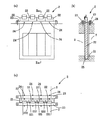
図4は、本発明の角落し構造の別の例を示す説明図である。
図4に示すように、この角落し構造4は、受け材41と複数の直方体からなる角落し42と横架材43と枠体45とくさび46とからなる。
【0026】
図4に示すように、この角落し構造4は、隧道をなすように天井部で上方が閉塞された状態の水路Sの堰止め部分には、ピットPが設けられ、ピットPの下方の水路幅方向の相対する側壁及び底壁に、ガイド溝41が設けられている。
【0027】
そのガイド溝41には、枠体45が装着されている。
枠体45は、上方が開放する略コ字状の形状を有していて、相対する枠板部451,451と相対する枠板部451,451を連結する横板部453,453と、枠板部451,451の底部間を連結する底板部452とからなる。枠板部451,451の上端部及び横板部453,453は、ピットPにシール材47を介してアングルAにて固定できるようになっている。
【0028】
枠板45の高さ方向の中間部及び上部には、横板部453,453を配設して、枠板45を一体構造にしている。この枠板45の構造より、角落し42とくさび46を打ち込むことでシール性が確保できる。
【0029】
枠体45は、枠板部451,451の水路Sに対応する部分が開口されており、少なくとも、水路Sの周囲のガイド溝41に対応する枠を形成する枠板部451,451及び底板部452の部分がガイド溝41の壁面にシール材47を介して当接するようになっている。尚、枠板部451,451は、隧道をなすように天井部に対応する部分の中央部も開口されている。
【0030】
枠体45の底板部452には、その上面の長手方向に沿って、後述する各角落とし42の下端部が係止される凹溝452aが設けられており、その凹溝452aの一側面が下方に向かうにつれて次第に狭まるような傾斜面452bとされている。
【0031】
角落し42は、直方体からなり、隣接する角落しと相対する面となる一側面に長手方向に沿って凸条421が設けられ、他側面に長手方向に沿って凹溝422が設けられており、上端部に前側面から後側面に貫通する浮上防止ピン挿通孔が設けられている。角落し42はその下端部の、上記枠体45の傾斜面452bに対応する部分に、下端に向かうにつれて次第に薄厚となるような傾斜面42bが設けられている。
46はくさびであって、隣接する角落し42と相対する面となる一側面に、その角落し42の他側面に設けられた凹溝422に嵌合する凸条461が長手方向に沿って設けられている。
【0032】
枠体45内に、水路幅方向に沿って、複数の角落し42がその長手方向を直立するようにして並設されている。最も側方となる2本の角落し42は、それぞれその外側部が、枠体45の枠板部451,451に係止されている。各角落し42の下端部は、枠体45の底板部452の凹溝452aに、その傾斜面452b,42b同士を摺動させるようにして、シール材48を介して係止されている。また、枠体45内で最も側方に位置する少なくとも一方の角落し42と隣接する枠体45の枠部材451との間にくさび46を打ち込むようにして、枠体45内に各角落し42を隙間なく閉塞することができるようになっている。
このシール材48は、角落し42の所定位置に貼り付けても良く、また枠体45のガイド溝41の下流側内面に貼り付けても良い。
【0033】
各角落し42の上端部は、枠体45の枠板部451,451の上端部及びピットPに固定されたアングルAに、浮上防止ピン44にて浮き上がらないように係止できるようになっている。また、各角落し42は、浮上防止ピン44を外して、くさび46を抜き取り、一側方から順番に上方に引き抜くことができるようになっている。
角落し42の材質としては、図1を参照して説明した角落し12と同様のものが採用できる。
また、枠体45の材質としては、角落し42と同材質で良く、また、金属製、FRPなどの合成樹脂製でも良い。
【0034】
そして、この角落し装置4において、水路を堰止めた状態から、流下させる処理水の水量調整を行うときには、流下させる処理水の水量に応じて、各角落し42を、浮上防止ピン44を外して、くさび45を抜き取り、必要な枚数だけ一側方から順番に上方に引き抜く。これにより、水路の底部付近の処理水であっても、所定の開口率にてその流れをコントロールすることができるので、処理効率を向上させることができる。
また、枠体45の固定状態を外して、各角落し42を固定した状態にて、枠体45ごと上方に引き上げるようにして、短時間にて水路Sの大きな開口を確保することもできる。
【0035】
【発明の効果】
本発明の角落し構造は、上記のとおりの構成とされているので、水路の底部付近の処理水であっても、所定の開口率にてその流れをコントロールすることができて、処理効率を向上させることができる。
【図面の簡単な説明】
【図1】本発明の角落し構造の一例を示す説明図であり、(a)はその正面図、(b)はそのI−I線に沿う断面図、(c)はその平面図である。
【図2】本発明の角落し構造の別の例を示す説明図であり、(a)はその正面図、(b)はそのII−II線に沿う断面図、(c)はその平面図である。
【図3】本発明の角落し構造の更に別の例を示す説明図であり、(a)はその正面図、(b)はそのIII−III線に沿う断面図、(c)はその平面図である。
【図4】本発明の角落し構造の更に別の例を示す説明図であり、(a)はその正面図、(b)はそのIV−IV線に沿う断面図、(c)はその平面図である。
【図5】従来の角落し構造の一例を示す正面図である。
【符号の説明】
1,2,3,4 角落し構造
11,21,31,41 ガイド溝
12,22,32,42 角落し
13,23,33 横架材
14,24,34,44 浮上防止ピン
45 枠体
46 くさび
25,35,47,48 シール材
A アングル
P ピット
S 水路[0001]
TECHNICAL FIELD OF THE INVENTION
BACKGROUND OF THE INVENTION 1. Field of the Invention The present invention relates to a corner drop structure for adjusting the amount of water in a waterway such as a sewerage facility or an agricultural waterway facility, or for blocking a waterway.
[0002]
[Prior art]
In order to block waterways such as sewage facilities, agricultural waterway facilities, and cultivation and fishery facilities, and to adjust the water volume, a corner drop structure that stacks multiple corner drops at the required height is installed at the required location of the waterway. .
[0003]
As a conventional corner-dropping structure, for example, as shown in FIG. 5, a plurality of corner-droppings a are placed in a guide groove b provided on a wall opposite to a water channel so that both ends are inserted in a horizontal state and both ends are inserted. (See Patent Document 1).
[0004]
However, in such a conventional angle-dropping structure, when adjusting the amount of water, it is necessary to remove only the upper few stages of a plurality of the angle-droppings a, so that the water is adjusted near the bottom of the water channel. However, there is a problem that the treated water cannot always be controlled and its flow cannot be controlled, and the treatment efficiency cannot be improved.
[0005]
[Patent Document 1]
JP-A-11-166225 [0006]
[Problems to be solved by the invention]
The present invention solves the conventional problems as described above, and can control the flow of treated water near the bottom of a water channel at a predetermined opening ratio, thereby improving cornering efficiency with improved treatment efficiency. It is intended to provide a structure.
[0007]
[Means for Solving the Problems]
The invention according to claim 1 of the present application is a corner dropping structure for blocking a water channel, wherein a guide groove is provided on a side wall and a bottom wall of the water channel in the width direction of the water channel opposite to each other. A corner drop structure composed of a plurality of rectangular parallelepipeds along the water channel width direction is arranged side by side so that its longitudinal direction is upright, and the upper ends of the corner drops are freely engageable with the horizontal member. It is.
[0008]
The invention according to claim 2 of the present application is the corner dropping structure according to claim 1, wherein the horizontal member is freely fixed to a water channel body.
[0009]
The invention according to claim 3 of the present application is a corner dropping structure for blocking a water channel, wherein a guide groove is provided on a side wall and a bottom wall of the blocking portion of the water channel which are opposed to each other in a width direction of the water channel. An approximately U-shaped frame body whose upper side is open is arranged and fixed, and a corner drop formed of a plurality of rectangular parallelepipeds is arranged side by side on the frame body so as to erect the longitudinal direction thereof along the water channel width direction. The corner-dropping structure is such that the upper ends of the corner-droppings are freely engageable with the frame.
[0010]
The invention according to claim 4 of the present application is the corner-dropping structure according to claim 3, wherein a wedge can be driven between the corner-dropping which is at least one side in the frame and the frame. .
[0011]
[Action]
The corner drop structure of the invention according to claim 1 of the present application is a corner drop structure for blocking a water channel, and a guide groove is provided on a side wall and a bottom wall of the blocking portion of the water channel opposite to each other in the water channel width direction. In the guide groove, a plurality of rectangular parallelepiped corners are arranged side by side in the width direction of the waterway so that the longitudinal direction thereof is erected, and the upper ends of the squared corners are made freely engageable with the horizontal members. By doing so, a plurality of corner cuts are arranged in the guide groove along the width direction so as to stand upright in the longitudinal direction and have a predetermined height, and the water drop is formed by locking those corner cuts to the horizontal member. When adjusting the flow rate of the treated water flowing down from the state in which the water channel is blocked, each angle drop can be blocked with a floating prevention pin with the horizontal member according to the flow rate of the treated water flowing down. , And pull up the required number of pieces from one side in order, It is possible to control the flow of the treated water near the bottom of the waterway at a constant aperture ratio, it is possible to improve the processing efficiency.
[0012]
In the corner drop structure of the invention according to claim 2 of the present application, since the horizontal member is freely fixed to the channel body, the water channel can be blocked so that each corner drop does not rise.
[0013]
The corner drop structure of the invention according to claim 3 of the present application is a corner drop structure for blocking a water channel, wherein guide grooves are provided on opposing side walls and a bottom wall in a water channel width direction of a blocking portion of the water channel. In the guide groove, a substantially U-shaped frame body whose upper side is open is disposed and fixed, and the corner drop formed by a plurality of rectangular parallelepipeds in the frame body along the water channel width direction so that its longitudinal direction is upright. Since the upper end portions of the corner cuts are freely latchable to the frame, a plurality of corner cuts are juxtaposed along the width direction of the frame so as to erect the longitudinal direction. The water channel can be blocked by locking the corner drop, and when adjusting the amount of the treated water flowing down from the state where the water channel is blocked, the treated water flowed down. Remove each corner drop according to the amount of water in By pulling up the required number of pieces in order from one side in order and controlling the flow of the treated water near the bottom of the water channel at a predetermined opening ratio, the processing efficiency can be improved and the frame body can be improved. By removing the fixed state of, the frame and the frame are lifted upward, so that a large opening of the water channel can be secured in a short time.
[0014]
The corner drop structure of the invention according to claim 4 of the present application is configured such that a wedge can be driven between at least one corner drop located at the sidemost side in the frame and the frame, so that the wedge can be driven. The water channel can be completely closed by driving in such a manner that each corner drop is tightly sealed in the frame without gaps.
[0015]
BEST MODE FOR CARRYING OUT THE INVENTION
Hereinafter, embodiments of the present invention will be described with reference to the drawings.
FIG. 1 is an explanatory diagram showing an example of a corner drop structure of the present invention.
As shown in FIG. 1, the corner drop structure 1 includes a guide groove 11 provided in a dam portion of a water channel S, a corner drop 12 formed of a plurality of rectangular parallelepipeds, and a horizontal member 13.
The guide grooves 11 are provided on opposing side walls and bottom walls in the water channel width direction of the dam portion of the water channel S.
[0016]
The corner drop 12 is formed of a rectangular parallelepiped, and a ridge 121 is provided on one side surface facing the adjacent corner drop along the longitudinal direction, and a concave groove 122 is provided on the other side surface along the longitudinal direction. A floating prevention pin insertion hole penetrating from the front side to the rear side is provided at the upper end.
As the angle drop 12, a material made of various materials such as metal, natural wood, synthetic wood, and synthetic resin can be used, but it is preferable to use a material having excellent corrosion resistance. Examples of the material having excellent corrosion resistance include a foam obtained by reinforcing a resin to be a hard foam with long glass fibers (for example, trade name “Eslon Neo Lumber FFU” manufactured by Sekisui Chemical Co., Ltd.) and the like. .
[0017]
As the resin which becomes a hard foam, for example, a hard urethane resin is preferably used. Examples of the fiber for reinforcing the resin include, in addition to glass fiber, inorganic fiber such as carbon fiber, metal fiber, and ceramic fiber, and organic fiber such as aromatic polyamide fiber. The fiber form is preferably long fibers such as yarn, cloth, roving, roving cloth, and cross mat, but if necessary, may be used in combination with short fibers such as chips and middle fibers and hollow fillers such as shirasu balloons. You can also.
[0018]
In the guide groove 11 of the water channel S, a plurality of corner recesses 12 are juxtaposed along the width direction of the water channel so that the longitudinal direction thereof is upright. The outermost portions of the two corner droppers 12 at the outermost sides are locked by guide grooves 11 provided on the side wall of the water channel S. The lower end of each corner drop 12 is engaged with a guide groove 11 provided on the bottom wall of the water channel S.
[0019]
The horizontal member 13 is stretched over the damming portion of the water channel S, and can be fixed to the water channel body with bolts.
The upper end portion of each corner drop 12 can be locked to a horizontal member 13 having both ends fixed to the water channel body S with bolts so as not to float with a floating prevention pin 14. In addition, each corner drop 12 can be pulled out sequentially from one side by removing the floating prevention pin 14 from the horizontal member 13.
[0020]
Then, in the angle dropping device 1, when adjusting the amount of treated water to flow down from the state where the water channel is blocked, each angle drop 12 is connected to the horizontal member 13 in accordance with the amount of treated water to flow down. The lifting prevention pins 14 are removed, and the required number of sheets are sequentially pulled upward from one side. Thereby, even if the treated water is near the bottom of the water channel, its flow can be controlled at a predetermined opening ratio, so that the treatment efficiency can be improved.
[0021]
FIG. 2 is an explanatory view showing another example of the corner drop structure of the present invention.
As shown in FIG. 2, the corner drop structure 2 includes a receiving member 21, a corner drop 22 formed of a plurality of rectangular parallelepipeds, and a horizontal member 23.
In this corner drop structure 2, guide grooves 21 are provided on opposing side walls and a bottom wall in a channel width direction of a blocking portion of a channel S whose upper part is closed so as to form a tunnel. A plurality of corner recesses 22 are arranged in the guide groove 21 along the water channel width direction so that the longitudinal direction thereof is upright. The outermost portions of the two corner droppers 12 at the outermost sides are locked by guide grooves 11 provided on the side wall of the water channel S. The lower end of each corner drop 12 is engaged with the guide groove 11 provided on the bottom wall of the water channel S via the sealing material 25.
The other structure is the same as that described with reference to FIG. 1, and therefore, the corresponding drawing numbers are assigned and the detailed description is omitted.
[0022]
When adjusting the flow rate of the treated water flowing down from the state where the water channel is blocked in the angle dropping device 2, each angled drop 22 is connected to the horizontal member 23 in accordance with the amount of the treated water flowing down. The lifting prevention pins 24 are removed, and the required number of the pins are pulled upward from one side in order. Thereby, even if the treated water is near the bottom of the water channel, its flow can be controlled at a predetermined opening ratio, so that the treatment efficiency can be improved.
[0023]
FIG. 3 is an explanatory view showing another example of the corner drop structure of the present invention.
As shown in FIG. 3, the corner drop structure 3 includes a receiving member 31, a corner drop 32 formed of a plurality of rectangular parallelepipeds, and a horizontal member 33.
In the corner dropping structure 3, the outermost two corner droppings 32 are engaged with the guide grooves 11 provided on the side wall of the water channel S with the sealing material 35 interposed therebetween. In addition, the upper end and the lower end of each corner drop 32 are engaged with a guide groove 31 provided on the bottom wall of the water passage S via the sealing material 35.
The other structure is the same as that described with reference to FIG. 2, and accordingly, the corresponding drawing numbers are assigned and detailed description thereof is omitted.
[0024]
Then, when adjusting the amount of treated water to flow down from the state where the water channel is blocked in the angle dropping device 3, each angle drop 32 is connected to the horizontal member 33 in accordance with the amount of treated water to flow down. The lifting prevention pins 34 are removed, and the required number of the pins are pulled upward from one side in order. Thereby, even if the treated water is near the bottom of the water channel, its flow can be controlled at a predetermined opening ratio, so that the treatment efficiency can be improved.
[0025]
FIG. 4 is an explanatory view showing another example of the corner drop structure of the present invention.
As shown in FIG. 4, the corner drop structure 4 includes a receiving member 41, a corner drop 42 formed of a plurality of rectangular parallelepipeds, a horizontal member 43, a frame 45, and a wedge 46.
[0026]
As shown in FIG. 4, this corner drop structure 4 is provided with a pit P at a damping portion of a water channel S in a state where the upper portion is closed at a ceiling so as to form a tunnel, and a water channel below the pit P is provided. Guide grooves 41 are provided on the side wall and the bottom wall that are opposed to each other in the width direction.
[0027]
A frame 45 is mounted in the guide groove 41.
The frame body 45 has a substantially U-shape that is open at the top, and has horizontal plate portions 453 and 453 connecting the opposed frame plate portions 451 and 451 and the opposed frame plate portions 451 and 451; It comprises a bottom plate portion 452 connecting the bottom portions of the plate portions 451 and 451. The upper end portions of the frame plate portions 451 and 451 and the horizontal plate portions 453 and 453 can be fixed to the pit P at an angle A via a sealing material 47.
[0028]
Horizontal plate portions 453 and 453 are disposed at the middle and upper portions of the frame plate 45 in the height direction, so that the frame plate 45 has an integral structure. With the structure of the frame plate 45, the sealing performance can be secured by driving the corner drop 42 and the wedge 46.
[0029]
In the frame body 45, portions of the frame plate portions 451 and 451 corresponding to the water passage S are opened, and at least the frame plate portions 451 and 451 and the bottom plate portion forming a frame corresponding to the guide groove 41 around the water passage S. The portion 452 comes into contact with the wall surface of the guide groove 41 via the sealing material 47. Note that the frame plate portions 451 and 451 are also opened at the center of the portion corresponding to the ceiling so as to form a tunnel.
[0030]
The bottom plate portion 452 of the frame body 45 is provided with a concave groove 452a along which the lower end of each corner drop 42 to be described later is locked, along one longitudinal side of the upper surface, and one side surface of the concave groove 452a. The inclined surface 452b gradually narrows downward.
[0031]
The corner drop 42 is formed of a rectangular parallelepiped, and is provided with a ridge 421 along the longitudinal direction on one side surface facing the adjacent corner drop, and a concave groove 422 along the longitudinal direction on the other side. A floating prevention pin insertion hole penetrating from the front side to the rear side is provided at the upper end. The angle drop 42 is provided with a sloped surface 42b at a lower end portion corresponding to the sloped surface 452b of the frame body 45 so as to become gradually thinner toward the lower end.
Reference numeral 46 denotes a wedge, on one side surface of which is opposed to the adjacent corner drop 42, a ridge 461 fitted in a concave groove 422 provided on the other side surface of the corner drop 42 is provided along the longitudinal direction. Has been.
[0032]
In the frame body 45, a plurality of corner cuts 42 are juxtaposed along the water channel width direction so that the longitudinal direction is upright. The outermost portions of the two corner droppers 42 that are the most lateral are respectively locked to frame plate portions 451 and 451 of the frame body 45. The lower end of each corner drop 42 is engaged with a concave groove 452a of a bottom plate 452 of the frame body 45 via a sealing material 48 such that the inclined surfaces 452b and 42b slide therebetween. In addition, the wedge 46 is driven between at least one corner drop 42 located at the sidemost position in the frame 45 and the frame member 451 of the adjacent frame 45 so that each corner drop 42 is inserted into the frame 45. Can be closed without gaps.
The seal member 48 may be attached to a predetermined position of the corner drop 42, or may be attached to the inner surface of the frame 45 on the downstream side of the guide groove 41.
[0033]
The upper end portion of each corner drop 42 can be locked to the upper end portions of the frame plate portions 451 and 451 of the frame body 45 and the angle A fixed to the pit P by the floating prevention pin 44 so as not to float. I have. Further, each corner drop 42 can be detached from the wedge 46 by removing the floating prevention pin 44, and can be pulled upward sequentially from one side.
As the material of the corner drop 42, the same material as the corner drop 12 described with reference to FIG. 1 can be adopted.
Further, the material of the frame body 45 may be the same material as that of the corner drop 42, or may be made of metal or synthetic resin such as FRP.
[0034]
When adjusting the flow rate of the treated water flowing down from the state where the water channel is blocked in the angle dropping device 4, remove each angle drop 42 and remove the floating prevention pin 44 according to the amount of the treated water flowing down. Then, the wedges 45 are extracted, and the required number of the wedges 45 are sequentially pulled upward from one side. Thereby, even if the treated water is near the bottom of the water channel, its flow can be controlled at a predetermined opening ratio, so that the treatment efficiency can be improved.
In addition, a large opening of the water channel S can be secured in a short time by removing the fixed state of the frame body 45 and pulling the frame body 45 upward in a state where each corner drop 42 is fixed.
[0035]
【The invention's effect】
Since the angle drop structure of the present invention is configured as described above, even for the treated water near the bottom of the water channel, the flow can be controlled at a predetermined opening ratio, and the treatment efficiency is improved. Can be improved.
[Brief description of the drawings]
FIGS. 1A and 1B are explanatory views showing an example of a corner drop structure of the present invention, wherein FIG. 1A is a front view, FIG. 1B is a cross-sectional view taken along line II, and FIG. .
FIGS. 2A and 2B are explanatory views showing another example of the corner drop structure of the present invention, wherein FIG. 2A is a front view, FIG. 2B is a cross-sectional view taken along line II-II, and FIG. It is.
3A and 3B are explanatory views showing still another example of the angle drop structure of the present invention, wherein FIG. 3A is a front view, FIG. 3B is a cross-sectional view along line III-III, and FIG. FIG.
4A and 4B are explanatory views showing still another example of the angle drop structure of the present invention, wherein FIG. 4A is a front view, FIG. 4B is a cross-sectional view taken along line IV-IV, and FIG. FIG.
FIG. 5 is a front view showing an example of a conventional corner drop structure.
[Explanation of symbols]
1, 2, 3, 4 Square dropping structures 11, 21, 31, 41 Guide grooves 12, 22, 32, 42 Square droppings 13, 23, 33 Horizontal members 14, 24, 34, 44 Floating prevention pins 45 Frame 46 Wedges 25, 35, 47, 48 Seal material A Angle P Pit S Waterway