JP2004238916A - Tool box for civil-engineering/construction machine also serving as step device - Google Patents
Tool box for civil-engineering/construction machine also serving as step device Download PDFInfo
- Publication number
- JP2004238916A JP2004238916A JP2003029299A JP2003029299A JP2004238916A JP 2004238916 A JP2004238916 A JP 2004238916A JP 2003029299 A JP2003029299 A JP 2003029299A JP 2003029299 A JP2003029299 A JP 2003029299A JP 2004238916 A JP2004238916 A JP 2004238916A
- Authority
- JP
- Japan
- Prior art keywords
- tool box
- lid
- box body
- construction machine
- cover material
- Prior art date
- Legal status (The legal status is an assumption and is not a legal conclusion. Google has not performed a legal analysis and makes no representation as to the accuracy of the status listed.)
- Pending
Links
Images


Classifications
-
- E—FIXED CONSTRUCTIONS
- E02—HYDRAULIC ENGINEERING; FOUNDATIONS; SOIL SHIFTING
- E02F—DREDGING; SOIL-SHIFTING
- E02F9/00—Component parts of dredgers or soil-shifting machines, not restricted to one of the kinds covered by groups E02F3/00 - E02F7/00
- E02F9/08—Superstructures; Supports for superstructures
- E02F9/0833—Improving access, e.g. for maintenance, steps for improving driver's access, handrails
Landscapes
- Engineering & Computer Science (AREA)
- Mining & Mineral Resources (AREA)
- Civil Engineering (AREA)
- General Engineering & Computer Science (AREA)
- Structural Engineering (AREA)
- Body Structure For Vehicles (AREA)
Abstract
Description
【0001】
【発明の属する技術分野】
この発明は、油圧ショベル等の土木・建設機械のステップ装置に関するもので、特に工具箱兼用のステップ装置に関するものである。
【0002】
【従来技術】
従来油圧ショベル等の土木・建設機械においては、上部旋回体に搭載されたエンジン、油圧機器、燃料タンク及び作動油タンク等を保護するためにハウスカバーが設けられている。そしてエンジンのメンテナンスや燃料タンクへの給油及び作動油の交換等はハウスカバーの上にオペレータ又はサービスマンが昇って行うため、上部旋回体には複数段のステップが設けられている。この複数段のステップのうち最下段のステップは通常上部旋回体を構成する旋回フレームに固着されており、オペレータ又はサービスマンは先ず履帯の上に乗り、そして旋回フレームに固着された最下段のステップに足を掛け、更にその上のステップを使ってハウスカバーの上に昇るため、ISOにより理想的なステップ間隔が定められ、例えば階段では180mm、梯子では300mm程度が理想とされている。一方、油圧ショベル等の土木・建設機械は狭隘な場所で使用されたり、作業現場間の輸送を考慮して旋回半径の超小化や外観形状寸法の小型化が図られ、逆に燃料タンクや作動油タンクは補充・交換時間が長くなるように大容量化が図られてきたため上部旋回体のハウスカバー内に工具箱の設置場所を設けることが困難になってきた。その結果、通常ステップを取り付ける位置に工具箱を取り付け、その工具箱をステップの代わりに使用するものも出現してきた(例えば、特許文献1参照)。
【0003】
【特許文献1】
特開平8−100444号公報(第2−3頁、図1乃至図6)。
【0004】
しかし、この特許文献1に開示されているステップ兼用工具箱は、上面部を開口した箱型に形成し、その上面部に踏面用の蓋板をヒンジ部材により開閉可能に装着したり、前面部又は側面部を開口した箱型に形成し、その開口した前面部又は側面部にカバー用の蓋板を設けたものである。一般に工具箱には工具を入れるため適当なデプスが必要であり、そのため履帯から踏面である工具箱の上面までの高さHが高くなりすぎ、オペレータ又はサービスマンが昇る際に膝及び足先を無理に高く上げる必要が生じ、その結果姿勢に無理を生じ、事故を誘発する頻度が高くなる等危険な状態に置かれる可能性があった。一方、ステップ高さをISOの推奨値に収めようとすると十分な工具箱のデプスをとることができず、全ての工具を収納できないという問題が生ずる。
【0005】
【発明が解決しようとする課題】
本発明は上記事実に鑑みなされたものであり、その目的は工具箱としての必要なデプスを確保するとともに、ステップの間隔をISOの推奨値内に収めるために工具箱本体の上面以外にその工具箱本体の上面と履帯との間に別のステップを必要に応じて作り出し、楽な姿勢でハウスカバーの上に昇ることが可能な工具箱兼用ステップを提供するために解決すべき技術的課題が生じてくるのであり、本発明はこの課題を解決することを目的とする。
【0006】
【課題を解決するための手段】
本発明は上記目的を達成するために提案されたものであり、請求項1記載の発明は下部走行体上に上部旋回体を旋回可能に装架し、該上部旋回体の外周部に昇降用ステップを配した土木・建設機械において、上部旋回体に前面部又は側面部を開口した工具箱本体を装着し、該工具箱本体の開口を覆う蓋材を開閉可能に蝶着して、該蓋材が開状態において該蓋材の上面と前記工具箱本体の上面を踏面とした土木・建設機械の工具箱兼用ステップ装置である。
【0007】
また、請求項2記載の発明は、蓋材が開状態において、該蓋材の踏面が工具箱本体の下面と略面一になるようにした土木・建設機械の工具箱兼用ステップ装置である。
【0008】
そして、請求項3記載の発明は、蓋材と工具箱本体を夫々下端部で蝶着し、該工具箱本体の側面に設けたピンに接して摺動する長孔を有する円弧状のガイドの一端を前記蓋材の側面上部に固設し、該蓋材を前記蝶着点回りに略90度開閉可能にした土木・建設機械の工具箱兼用ステップ装置である。
【0009】
【発明の実施の形態】
以下本発明の実施形態を図1乃至図4に基づいて説明する。
図1は本発明を採用した油圧ショベル全体側面図を示し、図2は本発明の実施形態に係る工具箱兼用ステップ取付部斜視図を示す。また、図3は本発明の実施形態に係る工具箱閉状態のステップ側面図を示し、図4は本発明の実施形態に係る工具箱開状態のステップ側面図を示す。
【0010】
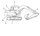
図1において、1は履帯1aを履いた下部走行体で、該下部走行体1には上部旋回体2が旋回可能に装架されている。そして該上部旋回体2を構成する旋回フレーム2aの前部には、一側部にキャブ3が載置され、中央部にアタッチメント4が俯仰動可能に枢着され、他側に燃料タンク、作動油タンク及び油圧機器(図示せず)が載置され、該燃料タンク、作動油タンク及び油圧機器の周囲にはこれらを保護するハウスカバー5が取り付けられている。
【0011】
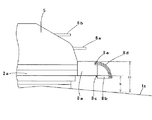
図2において、ハウスカバー5には少なくとも一つ以上のステップ6a、6b………が固設され、また、オペレータやサービスマンが昇降する際の転落を防止するハンドレール7が設けられている。そして、前記上部旋回体2の前部には、前面部に開口を設けた工具箱8が取り付けられている。
【0012】
図3において、上部旋回体2に固設した工具箱本体8aと該工具箱本体8aの開口を覆う蓋材8bを夫々の下端部で蝶番8cにより開閉可能に蝶着し、該工具箱本体8aの側面に設けたピン8eに接して摺動する長孔を有する円弧状のガイド8dの一端が前記蓋材8bの側面上部に固設され、該蓋材8bは前記蝶着点回りに略90度開閉可能になっている。そして、図3は該蓋材8bが閉状態を示し、この図3に示す状態においては、工具箱8に設けられた踏面は工具箱本体8aの上面1ヶ所だけであり、工具箱8のデプスを確保しようとすると工具箱本体8aの上面と履帯1aの上面との高さHが比較的大きくなりISOの推奨値を超えてしまい、オペレータやサービスマンが昇る際に危険を伴う恐れがある。
【0013】
次に、図4は前記蓋材8bを開状態にした場合を示し、図3の閉状態から前記蓋材8bを図の右回りに回動させると、該蓋材8bは蝶番8cを支点として開き始め、前記ガイド8dは工具箱本体8aに設けたピン8e上を摺動して前記蓋材8bが略90度回動したところで前記ピン8eがストッパーとして機能し、前記ガイド8dの長孔の端が前記ピン8eに当接して前記蓋材8bの回動が停止する。この図4に示す状態においては、前記工具箱8に設けられた踏面は工具箱本体8aの上面と蓋材8bの上面の2箇所あり、該蓋材8bの踏面は前記工具箱本体8aの下面と略面一となる。該工具箱本体8aの下面の位置及びデプスを適当に決めることにより、前記蓋材8bの踏面と履帯1aの上面との高さh及び前記工具箱本体8aの上面と蓋材8bの踏面の高さ(H−h)を自由に設定することが可能になり、オペレータやサービスマンはハウスカバーと履帯又は地面間の昇降が容易になる。
【0014】
次に本発明の作用を説明する。
通常の作業時においては、前記蓋材8bは図3の状態、すなわち閉状態にあり、該蓋材8bは図示されていないロック装置により工具箱本体8aにロックされており、旋回等により工具箱8の中に収納してある工具類が工具箱8から外に飛び出したり、落下することはない。次に、作業を中止してメンテナンス等のためハウスカバー上に昇るときは、地上から直接又は履帯1aの上に昇り、前記工具箱8のロック装置を解錠すると前記蓋材8bを開けることが可能になり、該蓋材8bに固設されているガイド8dが前記工具箱本体8aの側面に取り付けられているピン8eに接して摺動し、該蓋材8bは蝶番8cを支点として約90度回動し、前記ガイド8dに開穿された長孔の端が前記ピン8eに当接して停止する。
【0015】
この状態でオペレータ又はサービスマンは履帯1aから前記蓋材8bの踏面に一方の足を掛けると共にハンドレール7を手で掴み、次に他方の足を前記工具箱本体8aの踏面に掛けることにより、更に上のステップ6a、6b及びハウスカバーの上に容易に昇ることができる。逆にハウスカバーの上から地上に降りるときもステップ6b、6aから前記工具箱本体8aの踏面、蓋材8bの踏面及び履帯1aを介して容易に地上に降りることが可能になる。
【0016】
上記実施態様は、工具箱本体8aの前面部に開口を設け、該開口を覆う蓋材8bを前後方向に回動可能に装着したが、工具箱本体8aの側面部に開口を設け、該開口を覆う蓋材8b’を左右方向に回動することも可能であることは言うまでもない。
【0017】
更に、本発明は、本発明の精神を逸脱しない限り種々の改変を為すことができ、そして、本発明が該改変されたものに及ぶことは当然である。
【0018】
【発明の効果】
この発明は、上記一実施形態に於いて詳述した構成により、作業時には工具箱本体及び蓋材を本来の工具収納箱としての機能を持たせると共に、メンテナンス時には工具箱本体及び蓋材をステップとして用いることができ、特に蓋材を開けて踏面とすることにより、履帯と工具箱上面の間に別の踏面を作り出すことができるためステップ間隔を狭くすることができる。そのためオペレータやサービスマンは楽な姿勢で昇降でき、転落等の危険を防止できる等きわめて顕著な効果を奏する。
【図面の簡単な説明】
【図1】本発明を採用した油圧ショベル全体側面図
【図2】本発明の実施形態に係る工具箱兼用ステップ取付部斜視図
【図3】本発明の実施形態に係る工具箱閉状態のステップ側面図
【図4】本発明の実施形態に係る工具箱開状態のステップ側面図
【図5】従来のステップ兼用工具箱
【符号の説明】
1 下部走行体
1a 履帯
2 上部旋回体
2a 旋回フレーム
3 キャブ
4 アタッチメント
5 ハウスカバー
6a、6b ステップ
7 ハンドレール
8 工具箱
8a 工具箱本体
8b 蓋材
8c 蝶番
8d ガイド
8e ピン[0001]
TECHNICAL FIELD OF THE INVENTION
The present invention relates to a step device for a civil engineering / construction machine such as a hydraulic shovel, and more particularly to a step device that also serves as a tool box.
[0002]
[Prior art]
BACKGROUND ART Conventionally, in civil engineering and construction machines such as a hydraulic excavator, a house cover is provided to protect an engine, a hydraulic device, a fuel tank, a hydraulic oil tank, and the like mounted on an upper swing body. Since the maintenance of the engine, the refueling of the fuel tank, the replacement of the hydraulic oil, and the like are performed by an operator or a serviceman who ascends above the house cover, the upper revolving unit is provided with a plurality of steps. The lowermost step of the plurality of steps is usually fixed to the revolving frame constituting the upper revolving superstructure, and the operator or service person first rides on the crawler belt, and then the lowermost step fixed to the revolving frame. In addition, the ideal step interval is determined by the ISO, for example, 180 mm for a stair and about 300 mm for a ladder. On the other hand, civil engineering and construction machines such as hydraulic excavators are used in narrow spaces, and the turning radius and the external shape and dimensions are reduced in consideration of transportation between work sites. Since the capacity of the hydraulic oil tank has been increased so that the replenishment and replacement time becomes longer, it has become difficult to provide a place for installing a tool box in the house cover of the upper swing body. As a result, a tool box has been mounted at a position where a normal step is to be mounted, and the tool box has been used instead of the step (for example, see Patent Document 1).
[0003]
[Patent Document 1]
JP-A-8-100444 (page 2-3, FIGS. 1 to 6).
[0004]
However, the step-and-use tool box disclosed in Patent Document 1 is formed in a box shape with an open upper surface, and a tread cover plate is mounted on the upper surface so as to be openable and closable by a hinge member, Alternatively, it is formed in a box shape with an open side, and a cover plate for a cover is provided on the open front or side. In general, the tool box needs an appropriate depth to hold the tool, so that the height H from the crawler belt to the upper surface of the tool box, which is a tread, becomes too high. It was necessary to raise the height too high, which resulted in the posture being overwhelmed, and there was a possibility that the vehicle would be placed in a dangerous state, for example, the frequency of inducing an accident would increase. On the other hand, if the step height is to be kept within the recommended value of ISO, a sufficient depth of the tool box cannot be obtained, and a problem that all tools cannot be stored arises.
[0005]
[Problems to be solved by the invention]
SUMMARY OF THE INVENTION The present invention has been made in view of the above-described circumstances, and its purpose is to secure a necessary depth as a tool box and to set the interval between steps within the recommended value of ISO in addition to the upper surface of the tool box body. There is a technical problem to be solved in order to create another step between the upper surface of the box body and the crawler track as necessary and provide a tool box combined step that can climb on the house cover in an easy posture. The present invention aims to solve this problem.
[0006]
[Means for Solving the Problems]
SUMMARY OF THE INVENTION The present invention has been proposed to achieve the above object, and the invention according to claim 1 is provided with an upper revolving structure rotatably mounted on a lower traveling structure, and an elevating structure on an outer peripheral portion of the upper revolving structure. In a civil engineering / construction machine provided with steps, a tool box main body having an open front or side portion is mounted on an upper revolving structure, and a cover material covering an opening of the tool box main body is hinged so as to be openable and closable. A step device for a tool box of a civil engineering / construction machine, wherein the upper surface of the lid material and the upper surface of the tool box body are tread surfaces when the material is in an open state.
[0007]
According to a second aspect of the present invention, there is provided a step box device for a civil engineering / construction machine, wherein a tread surface of the lid material is substantially flush with a lower surface of the tool box body when the lid material is open.
[0008]
According to a third aspect of the present invention, there is provided an arc-shaped guide having an elongated hole in which a lid member and a tool box main body are hinged at lower ends, respectively, and slide in contact with pins provided on side surfaces of the tool box main body. A step box device for a civil engineering / construction machine wherein one end is fixed to an upper portion of a side surface of the lid member, and the lid member can be opened and closed by approximately 90 degrees around the hinged point.
[0009]
BEST MODE FOR CARRYING OUT THE INVENTION
Hereinafter, an embodiment of the present invention will be described with reference to FIGS.
FIG. 1 is an overall side view of a hydraulic shovel employing the present invention, and FIG. 2 is a perspective view of a tool box / step mounting portion according to an embodiment of the present invention. FIG. 3 shows a step side view in a tool box closed state according to the embodiment of the present invention, and FIG. 4 shows a step side view in a tool box open state according to the embodiment of the present invention.
[0010]
In FIG. 1, reference numeral 1 denotes a lower traveling body on which a
[0011]
In FIG. 2, at least one or
[0012]
In FIG. 3, a tool box main body 8a fixed to the upper revolving
[0013]
Next, FIG. 4 shows a case where the lid 8b is opened, and when the lid 8b is rotated clockwise from the closed state of FIG. 3, the lid 8b is pivoted about the
[0014]
Next, the operation of the present invention will be described.
During normal operation, the lid 8b is in the state shown in FIG. 3, that is, in a closed state, and the lid 8b is locked to the tool box body 8a by a lock device (not shown). The tools stored in the
[0015]
In this state, the operator or serviceman places one foot on the tread of the lid 8b from the
[0016]
In the above-described embodiment, an opening is provided on the front surface of the tool box body 8a, and the lid 8b that covers the opening is mounted rotatably in the front-rear direction. However, an opening is provided on the side surface of the tool box body 8a. Needless to say, it is also possible to rotate the lid 8b 'covering the right and left directions.
[0017]
Furthermore, the present invention can be variously modified without departing from the spirit of the present invention, and it goes without saying that the present invention extends to the modified ones.
[0018]
【The invention's effect】
According to the present invention, the tool box main body and the lid member have the function of the original tool storage box at the time of work, and the tool box main body and the lid member are used as steps at the time of maintenance by the configuration described in detail in the one embodiment. In particular, when the cover is opened to form a tread, another tread can be created between the crawler belt and the upper surface of the tool box, so that the step interval can be reduced. Therefore, the operator and the service person can move up and down in a comfortable posture, and can achieve a very remarkable effect such as a danger of falling down.
[Brief description of the drawings]
FIG. 1 is an overall side view of a hydraulic shovel employing the present invention. FIG. 2 is a perspective view of a tool box and step mounting portion according to an embodiment of the present invention. FIG. 3 is a step in a tool box closed state according to an embodiment of the present invention. FIG. 4 is a side view of a step in an open state of the tool box according to the embodiment of the present invention. FIG. 5 is a conventional step-and-use tool box.
DESCRIPTION OF SYMBOLS 1
Claims (3)
Priority Applications (1)
| Application Number | Priority Date | Filing Date | Title |
|---|---|---|---|
| JP2003029299A JP2004238916A (en) | 2003-02-06 | 2003-02-06 | Tool box for civil-engineering/construction machine also serving as step device |
Applications Claiming Priority (1)
| Application Number | Priority Date | Filing Date | Title |
|---|---|---|---|
| JP2003029299A JP2004238916A (en) | 2003-02-06 | 2003-02-06 | Tool box for civil-engineering/construction machine also serving as step device |
Publications (1)
| Publication Number | Publication Date |
|---|---|
| JP2004238916A true JP2004238916A (en) | 2004-08-26 |
Family
ID=32956507
Family Applications (1)
| Application Number | Title | Priority Date | Filing Date |
|---|---|---|---|
| JP2003029299A Pending JP2004238916A (en) | 2003-02-06 | 2003-02-06 | Tool box for civil-engineering/construction machine also serving as step device |
Country Status (1)
| Country | Link |
|---|---|
| JP (1) | JP2004238916A (en) |
Cited By (5)
| Publication number | Priority date | Publication date | Assignee | Title |
|---|---|---|---|---|
| EP1911890A2 (en) | 2006-10-10 | 2008-04-16 | Kobleco Construction Machinery Co., Ltd. | Construction machine |
| JP2008111253A (en) * | 2006-10-30 | 2008-05-15 | Hitachi Constr Mach Co Ltd | Revolving work machine |
| JP2013163894A (en) * | 2012-02-09 | 2013-08-22 | Hitachi Constr Mach Co Ltd | Work machine |
| JP2019173359A (en) * | 2018-03-28 | 2019-10-10 | 株式会社日立建機ティエラ | Construction machine |
| CN113653123A (en) * | 2021-09-23 | 2021-11-16 | 扬州扬子到河复合材料制品有限公司 | Multifunctional excavator tool box rear cover and machining process thereof |
-
2003
- 2003-02-06 JP JP2003029299A patent/JP2004238916A/en active Pending
Cited By (8)
| Publication number | Priority date | Publication date | Assignee | Title |
|---|---|---|---|---|
| EP1911890A2 (en) | 2006-10-10 | 2008-04-16 | Kobleco Construction Machinery Co., Ltd. | Construction machine |
| EP1911890A3 (en) * | 2006-10-10 | 2009-05-20 | Kobleco Construction Machinery Co., Ltd. | Construction machine |
| US7988167B2 (en) | 2006-10-10 | 2011-08-02 | Kobelco Construction Machinery Co., Ltd. | Construction machine |
| JP2008111253A (en) * | 2006-10-30 | 2008-05-15 | Hitachi Constr Mach Co Ltd | Revolving work machine |
| JP4676412B2 (en) * | 2006-10-30 | 2011-04-27 | 日立建機株式会社 | Swivel work machine |
| JP2013163894A (en) * | 2012-02-09 | 2013-08-22 | Hitachi Constr Mach Co Ltd | Work machine |
| JP2019173359A (en) * | 2018-03-28 | 2019-10-10 | 株式会社日立建機ティエラ | Construction machine |
| CN113653123A (en) * | 2021-09-23 | 2021-11-16 | 扬州扬子到河复合材料制品有限公司 | Multifunctional excavator tool box rear cover and machining process thereof |
Similar Documents
| Publication | Publication Date | Title |
|---|---|---|
| JP5192959B2 (en) | Construction machine having a toolbox opened in the front direction | |
| JP5152027B2 (en) | Toolbox structure | |
| US20130259626A1 (en) | Counterweight system for an industrial machine | |
| US20110018308A1 (en) | Dressing cover structure in construction machine | |
| JP2004238916A (en) | Tool box for civil-engineering/construction machine also serving as step device | |
| JP3589575B2 (en) | Revolving superstructure of construction equipment | |
| JP4172308B2 (en) | Construction machine floor structure assembling method and floor mat | |
| JP2001279714A (en) | Cover, handle and step in hydraulic shovel | |
| JP5257117B2 (en) | Construction machine step structure | |
| JP2002256593A (en) | Elevating step structure in construction machine | |
| JP3466952B2 (en) | Swiveling construction machine | |
| JPH08100444A (en) | Tool box device for construction machine | |
| JP5054802B2 (en) | Construction machinery | |
| JP4175985B2 (en) | Step and construction machinery | |
| JP2004143887A (en) | Structure of handle for ascent/descent to/from hydraulic excavator | |
| JP2004116102A (en) | Tool storage device of hydraulic shovel | |
| JPH10266264A (en) | Storage box in construction machine | |
| JP4023963B2 (en) | Excavator step device | |
| JP2583666Y2 (en) | Revolving superstructure of construction equipment | |
| JP2023142145A (en) | Construction machine | |
| KR0132035Y1 (en) | Boom swing pedal cover for an excavator | |
| JP2007170018A (en) | Step structure of construction machine | |
| JP5952893B2 (en) | Small excavator | |
| JP6786902B2 (en) | Handrail structure of work vehicle | |
| JP2003192272A (en) | Construction machinery |
Legal Events
| Date | Code | Title | Description |
|---|---|---|---|
| A977 | Report on retrieval |
Free format text: JAPANESE INTERMEDIATE CODE: A971007 Effective date: 20060322 |
|
| A131 | Notification of reasons for refusal |
Free format text: JAPANESE INTERMEDIATE CODE: A131 Effective date: 20060327 |
|
| A521 | Written amendment |
Free format text: JAPANESE INTERMEDIATE CODE: A523 Effective date: 20060524 |
|
| A02 | Decision of refusal |
Free format text: JAPANESE INTERMEDIATE CODE: A02 Effective date: 20060725 |