JP2004238031A - Cold insulation box - Google Patents
Cold insulation box Download PDFInfo
- Publication number
- JP2004238031A JP2004238031A JP2003029035A JP2003029035A JP2004238031A JP 2004238031 A JP2004238031 A JP 2004238031A JP 2003029035 A JP2003029035 A JP 2003029035A JP 2003029035 A JP2003029035 A JP 2003029035A JP 2004238031 A JP2004238031 A JP 2004238031A
- Authority
- JP
- Japan
- Prior art keywords
- belt
- hook
- wall
- insertion hole
- mounting portion
- Prior art date
- Legal status (The legal status is an assumption and is not a legal conclusion. Google has not performed a legal analysis and makes no representation as to the accuracy of the status listed.)
- Granted
Links
Images

Abstract
Description
【0001】
【発明の属する技術分野】
本発明は、釣りその他のレジャー等において使用でき、人が運搬可能な大きさの保冷箱に関する。
【0002】
【従来の技術】
上方に開口する箱状の容器本体と、該開口部に蓋をする蓋部材を有し、運搬用に、容器本体の対向する側面にベルト装着部を設け、該装着部にベルトを装着し、手で提げたり、或いは肩に掛けることができるように構成した、所謂、保冷箱が従来から使用されている。例えば、下記特許文献1には、ベルト端部をベルト装着部の爪部に摩擦で係止させる構造の保冷箱が開示されている。また、下記特許文献2には、ベルトの端部にベルト係止具を取り付け、一方、ベルト装着部には前記ベルト係止具を挿入可能であって、挿入後に方向を変えて係止できるベルト嵌合孔を設けた保冷箱が開示されている。一般に、ベルトは、使用目的や使用形態からして丈夫に、即ち、ベルト厚さを所定厚さにし、ベルト幅を所定の大きさにして耐久性を持たせるように形成している。
【特許文献1】
実開昭57−3970号公報
【特許文献2】
特開2001−315790号公報
【0003】
【発明が解決しようとする課題】
文献1の構造では、爪部にベルト端部を係合させることに時間を要するため、簡便化が求められていた。これを改善した形態の1つといえる文献2では、ベルト係止具をベルト嵌合孔に挿入する際に、ベルト係止具近くのベルトを90度捩る必要がある。上述の如く耐久性向上のため、ベルトは或る程度の剛性を持たせてあり、ベルト端部を90度程度捩ることは大きな抵抗感を有し、高品質な製品を求める現在においては、着脱を行うことが面倒に感じられる。
【0004】
依って本発明は、ベルト端部をベルト装着部に係止させる場合にはワンタッチ式に可能であって、不用意に外れ難い装着構造を有する保冷箱の提供を目的とする。
【0005】
【課題を解決するための手段】
上記目的に鑑みて本発明は、容器本体の対向する側面に設けたベルト装着部の少なくとも一方は、上下に開口する挿通孔を有すると共に、フック装置のフックを、ベルト延伸先側が係止部である向きにしてベルトに取り付けており、前記ベルト装着部には、前記挿通孔の下端よりも高い位置であってベルト装着部の側面部に、前記挿通孔の挿通方向に交差する方向に沿って、ベルトの幅方向に沿った前記係止部の形状に対応した係合孔が設けてあることを特徴とする保冷箱を提供する。
【0006】
上下に開口する挿通孔の上から、ベルトのフック装置側を挿通させてベルトを通す。このフック装置のフックはベルト延伸先側が係止部であり、ベルト装着部にはフックの幅方向に沿った係止部形状に対応した係合孔を、ベルト装着部の側面部に、挿通孔の挿通方向に交差する方向に沿って設けているため、ベルトを上方向に折り返すだけで、殆ど捩ることなくより高い位置にある係合孔に先部のフック係止部を係合させることができる。そうしてベルトを肩に掛ける等すれば、保冷箱の重さによってベルトに張力が掛かり、先部のフック係止部も係合孔の下縁を押圧するようにして係止する。ベルトを離しても、フック装置等の重さによって係止部は係合孔に係止したままとなる。
【0007】
請求項2では、係止された状態におけるフックの、前記ベルト装着部の壁に対面する側に、凹部又は凸部が設けられており、該凹部か凸部に対応するベルト装着部の位置に、係合可能な凸部又は凹部を設けている請求項1記載の保冷箱を提供する。
フックの凹部か凸部が、対応するベルト装着部側の凸部か凹部に係合できるので、運搬中等の揺動に対して、フックがベルト装着部に対して揺れる等の相対挙動を防止できる。従って、それだけ不用意に外れ難くなる。
【0008】
請求項3では、前記ベルト装着部は、前記挿通孔の外側方向に位置する壁部の下端部が傾斜状に形成されており、該傾斜状部の容器本体に近い端部と遠い端部の内の鋭角部である一方の端部を越えた位置で、ベルトが前記フック装置に取り付けられている請求項1又は2記載の保冷箱を提供する。
ベルトは鋭角部の前後に亘っているため、運搬中、傾斜状部の鋭角部によって押圧されることになる。このため、ベルトには鋭角部によって一種の引っ掛り現象が生じ、運搬による衝撃や揺動が生じた場合の瞬間的なベルトの緩みはフック装置を取り付けた側のベルトには及び難くなる。従って、不用意にフック係止部が係合孔から外れることを防止できる。
【0009】
請求項4では、ベルトは、前記係合孔の設けられているベルト装着部の、係合孔を有する壁の下端を越えた係合孔寄りの位置でフック装置に取り付けられ、ベルトを提げた運搬状態において、ベルトはその折り返し領域では前記壁の下端部のみを押圧しながら挿通孔の上方向に延伸する請求項1又は2記載の保冷箱を提供する。
ベルトは、係合孔の設けられている壁の下端部の前後に亘っている構成であって、該下端部のみを押圧して上方に延伸しているため、この部位でのベルトの折れ曲りは急であり、請求項3における鋭角部に類似の効果を奏し、引っ掛りを生じ、不用意にフック係止部が係合孔から外れることを防止できる。
【0010】
【発明の実施の形態】
以下、本発明を添付図面に示す実施形態例に基づき、更に詳細に説明する。
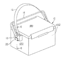
図1は本発明に係る保冷箱の例としての、釣りに使用するクーラーである。容器部10は直方体状であり、容器本体の上部が開口部になっている。この開口部に蓋10Uを被せて使用する。容器本体の対向する側面壁10S1,10S2の外側面にはベルト装着部12が設けられている。この装着部にはショルダーベルト(以下、ベルト)16の他、手提げ用のハンドル14が装着されている。ハンドルは回動自在に装着されている。
【0011】
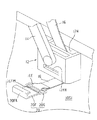
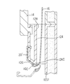
図2は装着部12付近の拡大図であり、図3は図1の矢視線C−Cによる拡大縦断面図である。側面壁10S1と、該壁に対面する(概ね平行な)装着部側の第1壁12Aとの間には、上下方向に挿通した挿通孔12Hが設けられている。該孔は側面壁10S1の面に沿って幅広であり、側面壁と第1壁との離隔距離は幅狭である。本形態例では、第1壁の外側に離隔して、該第1壁もしくは側面壁10S1と概ね平行な第2壁(側面部)12Bが設けられており、両壁の下端部は第1壁側が低くなるように傾斜した傾斜壁12Cによって連続している。ベルト16の端部にはフック装置20が取り付けられている。
【0012】
上記挿通孔12Hの上端開口部からフック装置を挿通させ、下端開口部から外に出してベルトを挿通させる。この例のフック装置20は、係止部20FKを有するフック20Fと、該フックの後端部に回動自在に取り付けられたバックル等の中間部材20Gとを有している。ベルト端部16Eはフック装置の係止部とは反対側端部である中間部材に対して回動可能に取り付けられている。該中間部材は、フック後端部に対して回動自在であるため、これにベルト端部を取り付けても、そのベルト端部の厚いベルト2重部が壁と干渉して、フックを後述の係合孔12KHから外すような力を作用させないために設けている。
【0013】
一方、装着部の側面部である第2壁12Bは、ベルトを捩ることなく係止できるように容器本体の側面と同様の方向(概ね平行)に設け、その所定位置には、フック係止部の係合できる係合孔12KHが左右方向に沿って設けられている。図2によって明白であるが、フック20Fは、ベルトの延伸先側に係止部20FKが位置するように取り付けられている。また、フックはベルト延伸方向に沿った縦断面がJの字形状をし、先部の係止部以外は平板であるが、平板には限らず、湾曲板等も可である。また、フック全体縦断面形状Jも係止部(Jの先部)形状も、ベルトの幅方向に沿って一定である。従って、この係止部を係合させる係合孔12KHの下縁を第2壁において、前記挿通孔12Hの上下方向に対して直交する交差方向(左右方向)に沿って直線に形成することにより、フック係止部の前記ベルト幅方向全体を係合孔の下縁に当接できる。また、係合の際には、フック20Fの係合部20FKはベルト16を挿通孔12Hに挿通した時、側面壁10S1と対面するベルトの面とは反対面側に(突出するように)設けられており、挿通孔下端から引き出したフックを、ベルトを捩ることなく、単に上方に折り返すだけで、係合部FKが係合孔12KHに向かい合った状態となり、そのまま移動させて係合孔に差し込むことで、ベルト装着部の側面部の第2壁12Bの係合孔に係止させることができる。
【0014】
この直線状の係合孔12KHによってフックとの係止を充分に行える。該係合孔の上下方向幅は、フック係止部20FKが孔内に挿入できる範囲でできるだけ狭くすることが、クーラー運搬中においてフックが不用意に外れることの防止に役立つが、係合孔の下縁以外の(上部や側部の縁)形状は任意である。しかし、係合孔の下縁も、例えば、凹凸や波状に形成されていても、それらの上端を連ねると直線状になっていればよい。フックの幅寸法以内の離隔距離に、2つの凸部が設けられていて、その凸部の上端を結ぶと左右方向であってもよい。フック係止部の形状に対応するとはこうした意味である。
【0015】
その他、フックの縦断面寸法形状がベルト幅方向において変化する場合、例えば、該幅方向に沿って漸次長くなり、また、短くなる形状の場合、即ち、フック係止部形状が山形や円弧状に折れ曲ったりカーブしている場合は、係合孔の下縁ラインもこれに応じた山形や円弧状に形成する。
【0016】
この形態例では、フック後端部を筒状に曲げ、これに中間部材20Gを回動自在に取り付けている。フックを係止させた状態で、この筒状曲げ部20FMが対面している壁部、この場合は傾斜壁12Cに、該曲げ部の対面部分(凸部)が収納される凹部12CKを形成している。これにより、クーラーの運搬中にガタついてフックが外れることを防止できる。また、傾斜壁12C下端部と第1壁12A下端部との交差部12ACは鋭角状である。ベルト端部16Eは中間部材の後端部に取り付けられているが、このベルト端部は前記鋭角交差部12ACの位置よりも係合孔に近く位置している。従って、ベルトを肩に掛けて運搬する際、ベルトは鋭角交差部によって強く押圧され、瞬間的に揺れてベルトが弛もうとしても、その弛みがフック側にまで及び難い。
【0017】
傾斜壁は平面である必要は無く、曲面であってもよい。また、この例とは異なり、第1壁の下端よりも第2壁12Bの下端の方が低く、上記例とは逆方向に傾斜した傾斜壁であってもよい。この場合、鋭角交差部は傾斜壁と第2壁下端部との交差部であるため、ベルト端部16Eはこの交差部よりも係合孔寄りに位置する必要がある。
【0018】
図4は他の形態例を示し、図3に対応した図である。第1形態例と異なる事項を説明する。フック装置20’はフックそのものであり、第1形態例の中間部材をも兼ねた形状のへの字状に曲げられ、傾斜壁12C方向にへの字に曲っているが、沿わせてはいない。即ち、フックを係合孔12KHに係止させた場合に、ベルト端部16Eを取りつける部位であるフック後端部が傾斜壁から所定量離隔するように、への字の曲げ角度を設定している。これにより、ベルト端部を取り付けた場合に、ベルト端部の2重部厚さによって、フックを係合孔から外す力の作用することを防止している。
【0019】
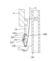
図5は、更に他の形態例であり、図3に対応する図である。第1形態例と異なる事項を説明する。第1壁は無く、挿通孔12H’は第2壁と側面壁10S1とで挟んだ空間領域である。また、傾斜壁も存在していない。フック装置20”はフックそのものである。その後端部にベルト端部16Eを取り付けているが、ベルト端部の厚い2重部が第2壁に干渉してフックを外すように作用することを防止すべく、フックの後部を第2壁から離隔する方向に曲げている。また、第2壁側には凹部12BKを設けており、該凹部に係合する寸法形状の凸部20K”をフックの第2壁側の面に設けている。従って、運搬中の揺動によってフックが外れ難い。この凸部は、左右方向に長い凸条でもよく、短い凸部でもよく、また、その個数も凹部12BKに係合できれば適宜数でよい。更には、逆に、壁側が凸部であり、フック側が凹部でもよい。
【0020】
フックに取り付けられたベルト端部16Eの位置は、第2壁の下端12BEよりも係合孔12KH寄りである。従って、運搬中ではベルトは第2壁部下端部によって鋭角的に折り返され、この折り返し部において幾分引っ掛るようになり、多少の揺動では、ベルトの本体部分(第2壁下端から端部16Eの部分を除いた部分)が緩んでも、その緩みが瞬間的にはフックには及び難い。
異なる形態例において説明した各事項は、特に矛盾のない限り、他の形態例にも適用できる。
【0021】
【発明の効果】
以上の説明から明らかなように本発明によれば、ベルト端部のフックをベルト装着部に係止させる場合にはワンタッチ式に可能であって、不用意に外れ難い装着構造を有する保冷箱の提供が可能になる。
【図面の簡単な説明】
【図1】図1は、本発明に係る保冷箱の斜視図である。
【図2】図2は、図1の要部拡大図である。
【図3】図3は、図1の矢視線C−Cによる拡大縦断面図である。
【図4】図4は、第2形態例を示す図である。
【図5】図5は、第3形態例を示す図である。
【符号の説明】
10S1,10S2 側面壁
12 ベルト装着部
12AC 鋭角交差部
12CK 凹部
12H 挿通孔
12KH 係合孔
16 ベルト
16E ベルト端部
20 フック装置
20F フック
20FK フック係止部
20FM 凸部(筒状曲げ部)[0001]
TECHNICAL FIELD OF THE INVENTION
The present invention relates to an insulated box that can be used in fishing and other leisure activities and that can be carried by a person.
[0002]
[Prior art]
A box-shaped container main body that opens upward, and a lid member that covers the opening, for transportation, a belt mounting portion is provided on the opposite side of the container main body, and a belt is mounted on the mounting portion, A so-called insulated box configured so that it can be held by hand or hung on a shoulder has been conventionally used. For example, Patent Literature 1 below discloses a cool box having a structure in which a belt end portion is engaged with a claw portion of a belt mounting portion by friction. Japanese Patent Application Laid-Open Publication No. H11-163873 discloses a belt capable of attaching a belt locking device to an end of a belt, while inserting the belt locking device into a belt mounting portion, and locking the belt in a different direction after insertion. A cool box provided with a fitting hole is disclosed. Generally, the belt is formed to be durable from the purpose of use and form of use, that is, the belt thickness is set to a predetermined thickness, and the belt width is set to a predetermined size to provide durability.
[Patent Document 1]
Japanese Utility Model Laid-Open No. 57-3970 [Patent Document 2]
JP 2001-315790 A
[Problems to be solved by the invention]
In the structure of Literature 1, since it takes time to engage the belt end with the pawl, simplification has been required. In Reference 2, which can be said to be one of the forms in which this is improved, it is necessary to twist the belt near the belt locking device by 90 degrees when inserting the belt locking device into the belt fitting hole. As described above, the belt is given a certain degree of rigidity in order to improve the durability. Twisting the belt end by about 90 degrees has a large resistance, and at present, high quality products are required. It feels troublesome to do.
[0004]
Therefore, an object of the present invention is to provide a cool box having a mounting structure that can be one-touch type when the belt end portion is locked to the belt mounting portion, and that is not easily detached accidentally.
[0005]
[Means for Solving the Problems]
In view of the above object, the present invention provides at least one of the belt mounting portions provided on opposing side surfaces of the container body, having an insertion hole that opens up and down, a hook of the hook device, and a belt extension destination side with a locking portion. Attached to the belt in a certain direction, the belt mounting portion, at a position higher than the lower end of the insertion hole, on the side portion of the belt mounting portion, along the direction intersecting the insertion direction of the insertion hole In addition, the present invention provides a cool box, wherein an engagement hole corresponding to the shape of the locking portion is provided along the width direction of the belt.
[0006]
The belt is passed through the hook device side of the belt from above the vertically opened insertion hole. The hook of this hook device has a locking portion on the belt extension side, and an engaging hole corresponding to the locking portion shape along the width direction of the hook is provided in the belt mounting portion, and an insertion hole is provided in a side portion of the belt mounting portion. Is provided along the direction that intersects the insertion direction, so that the hook hooking portion at the leading end can be engaged with the engaging hole at a higher position with almost no twist by simply folding the belt upward. it can. When the belt is hung on the shoulder, tension is applied to the belt by the weight of the cool box, and the hook engaging portion at the front end is also engaged by pressing the lower edge of the engaging hole. Even when the belt is released, the locking portion remains locked in the engagement hole due to the weight of the hook device or the like.
[0007]
According to claim 2, a concave portion or a convex portion is provided on a side of the hook in a locked state facing the wall of the belt mounting portion, and the hook is provided at a position of the belt mounting portion corresponding to the concave portion or the convex portion. The cold storage box according to claim 1, wherein a convex portion or a concave portion engageable is provided.
Since the concave portion or the convex portion of the hook can engage with the corresponding convex portion or concave portion on the belt mounting portion side, it is possible to prevent relative behavior such as swinging of the hook with respect to the belt mounting portion against rocking during transportation or the like. . Therefore, it becomes difficult to come off carelessly.
[0008]
According to the third aspect, in the belt mounting portion, a lower end portion of a wall portion located in an outer direction of the insertion hole is formed in an inclined shape, and an end portion of the inclined portion closer to and far from the container body is formed. 3. The cool box according to claim 1, wherein a belt is attached to the hook device at a position beyond one end which is an acute angle portion in the inside.
Since the belt extends around the acute angle portion, the belt is pressed by the acute angle portion of the inclined portion during transportation. For this reason, a kind of catching phenomenon occurs in the belt due to the acute angle portion, and it becomes difficult for the belt to be momentarily loosened when the impact or swing occurs due to the conveyance, to the belt on which the hook device is attached. Therefore, it is possible to prevent the hook locking portion from being accidentally detached from the engagement hole.
[0009]
According to the fourth aspect, the belt is attached to the hook device at a position near the engagement hole beyond the lower end of the wall having the engagement hole in the belt mounting portion provided with the engagement hole, and the belt is hung. The cold storage box according to claim 1 or 2, wherein in a transport state, the belt extends upward in the insertion hole while pressing only the lower end of the wall in the folded area.
The belt is formed so as to extend before and after the lower end of the wall provided with the engagement hole. Since the belt extends upward by pressing only the lower end, the belt is bent at this portion. Is steep, has an effect similar to that of the acute angle portion in claim 3, can be caught, and can prevent the hook locking portion from coming out of the engagement hole carelessly.
[0010]
BEST MODE FOR CARRYING OUT THE INVENTION
Hereinafter, the present invention will be described in more detail based on embodiments shown in the accompanying drawings.
FIG. 1 shows a cooler used for fishing as an example of a cool box according to the present invention. The
[0011]
FIG. 2 is an enlarged view of the vicinity of the
[0012]
The hook device is inserted through the upper end opening of the
[0013]
On the other hand, the second wall 12B, which is the side surface of the mounting portion, is provided in the same direction (substantially parallel) as the side surface of the container main body so that the belt can be locked without twisting. Are provided along the left-right direction. As is apparent from FIG. 2, the
[0014]
The engagement with the hook can be sufficiently performed by the linear engagement holes 12KH. The width of the engaging hole in the vertical direction should be as narrow as possible within a range in which the hook engaging portion 20FK can be inserted into the hole. This helps prevent the hook from being accidentally detached during transportation of the cooler. The shape other than the lower edge (the upper or side edge) is arbitrary. However, even if the lower edge of the engagement hole is formed in, for example, an uneven shape or a wavy shape, the lower edge of the engagement hole may be linear as long as the upper ends thereof are connected. Two protrusions may be provided at a separation distance within the width of the hook, and the upper ends of the protrusions may be connected in the left-right direction. To correspond to the shape of the hook engaging portion has such a meaning.
[0015]
In addition, when the vertical cross-sectional dimension of the hook changes in the belt width direction, for example, it gradually increases along the width direction, and also becomes shorter, that is, the hook locking portion shape becomes a mountain shape or an arc shape. If the engagement hole is bent or curved, the lower edge line of the engagement hole is also formed in a mountain shape or an arc shape corresponding thereto.
[0016]
In this embodiment, the rear end of the hook is bent into a cylindrical shape, and the intermediate member 20G is rotatably attached to the rear end. In a state where the hook is locked, a concave portion 12CK for accommodating a facing portion (convex portion) of the bent portion is formed in a wall portion facing the cylindrical bent portion 20FM, in this case, an inclined wall 12C. ing. Thus, it is possible to prevent the hook from coming loose due to backlash during transportation of the cooler. The intersection 12AC between the lower end of the inclined wall 12C and the lower end of the
[0017]
The inclined wall need not be flat, but may be curved. Further, unlike this example, the lower end of the second wall 12B may be lower than the lower end of the first wall, and the inclined wall may be inclined in a direction opposite to the above example. In this case, since the acute angle intersection is the intersection of the inclined wall and the lower end of the second wall, the belt end 16E needs to be located closer to the engagement hole than this intersection.
[0018]
FIG. 4 shows another embodiment, and is a diagram corresponding to FIG. Matters different from the first embodiment will be described. The
[0019]
FIG. 5 shows still another embodiment and corresponds to FIG. Matters different from the first embodiment will be described. There is no first wall, and the
[0020]
The position of the
The items described in the different embodiments can be applied to other embodiments unless there is a particular contradiction.
[0021]
【The invention's effect】
As is apparent from the above description, according to the present invention, when the hook at the end of the belt is to be locked to the belt mounting portion, it is possible to use a one-touch method, Provision becomes possible.
[Brief description of the drawings]
FIG. 1 is a perspective view of a cool box according to the present invention.
FIG. 2 is an enlarged view of a main part of FIG. 1;
FIG. 3 is an enlarged vertical sectional view taken along line CC of FIG. 1;
FIG. 4 is a diagram showing a second embodiment.
FIG. 5 is a diagram showing a third embodiment.
[Explanation of symbols]
10S1,
Claims (4)
Priority Applications (1)
| Application Number | Priority Date | Filing Date | Title |
|---|---|---|---|
| JP2003029035A JP4086147B2 (en) | 2003-02-06 | 2003-02-06 | Cold box |
Applications Claiming Priority (1)
| Application Number | Priority Date | Filing Date | Title |
|---|---|---|---|
| JP2003029035A JP4086147B2 (en) | 2003-02-06 | 2003-02-06 | Cold box |
Publications (2)
| Publication Number | Publication Date |
|---|---|
| JP2004238031A true JP2004238031A (en) | 2004-08-26 |
| JP4086147B2 JP4086147B2 (en) | 2008-05-14 |
Family
ID=32956320
Family Applications (1)
| Application Number | Title | Priority Date | Filing Date |
|---|---|---|---|
| JP2003029035A Expired - Lifetime JP4086147B2 (en) | 2003-02-06 | 2003-02-06 | Cold box |
Country Status (1)
| Country | Link |
|---|---|
| JP (1) | JP4086147B2 (en) |
Cited By (2)
| Publication number | Priority date | Publication date | Assignee | Title |
|---|---|---|---|---|
| JP2008265836A (en) * | 2007-04-23 | 2008-11-06 | Shimano Inc | Mounting structure of conveyance member for cooler box |
| JP2012176806A (en) * | 2012-05-15 | 2012-09-13 | Shimano Inc | Mounting structure of conveyance member for cooler box |
-
2003
- 2003-02-06 JP JP2003029035A patent/JP4086147B2/en not_active Expired - Lifetime
Cited By (3)
| Publication number | Priority date | Publication date | Assignee | Title |
|---|---|---|---|---|
| JP2008265836A (en) * | 2007-04-23 | 2008-11-06 | Shimano Inc | Mounting structure of conveyance member for cooler box |
| TWI574617B (en) * | 2007-04-23 | 2017-03-21 | Shimano Kk | The mounting structure of the container for moving the cold box |
| JP2012176806A (en) * | 2012-05-15 | 2012-09-13 | Shimano Inc | Mounting structure of conveyance member for cooler box |
Also Published As
| Publication number | Publication date |
|---|---|
| JP4086147B2 (en) | 2008-05-14 |
Similar Documents
| Publication | Publication Date | Title |
|---|---|---|
| JP2018039564A (en) | Cool box | |
| US20180236904A1 (en) | Child safety seat | |
| EP1285598A1 (en) | Security bag | |
| JP2004238031A (en) | Cold insulation box | |
| JP2004329736A (en) | Sheet mounting instrument and sheet mounting member | |
| JP2007314221A (en) | Attachment structure of decorative card in case | |
| JP5789561B2 (en) | Latching device | |
| JP2005058442A (en) | Buckle | |
| US7422402B2 (en) | Anchoring device | |
| JP2010070035A (en) | Vehicular accessory box | |
| JP2006248183A (en) | Coating film transfer implement | |
| JP2003236772A (en) | Storage case for power tool | |
| JP7390714B2 (en) | article holder | |
| JP5044271B2 (en) | Cooling box transport member mounting structure | |
| JP3579795B2 (en) | Bag holder and its use | |
| JP2018042777A (en) | Storage case with handle | |
| JPH11324428A (en) | Combination of key and keeping tool thereof | |
| JP2005144012A (en) | Puncture holding device and puncture holder hanger | |
| WO2012086611A1 (en) | Cord fastener | |
| JP2637673B2 (en) | Sealing devices such as coin storage bags and other packaging bags | |
| JP2007076680A (en) | Packaging box and package | |
| JP2001315790A (en) | Container | |
| JP2004065560A (en) | Lid hook structure of rice cooker | |
| JP2000000047A (en) | Cooler box | |
| JP2001058635A (en) | Folding container |
Legal Events
| Date | Code | Title | Description |
|---|---|---|---|
| A621 | Written request for application examination |
Free format text: JAPANESE INTERMEDIATE CODE: A621 Effective date: 20050921 |
|
| A977 | Report on retrieval |
Free format text: JAPANESE INTERMEDIATE CODE: A971007 Effective date: 20070806 |
|
| A131 | Notification of reasons for refusal |
Free format text: JAPANESE INTERMEDIATE CODE: A131 Effective date: 20070820 |
|
| TRDD | Decision of grant or rejection written | ||
| A01 | Written decision to grant a patent or to grant a registration (utility model) |
Free format text: JAPANESE INTERMEDIATE CODE: A01 Effective date: 20080213 |
|
| A61 | First payment of annual fees (during grant procedure) |
Free format text: JAPANESE INTERMEDIATE CODE: A61 Effective date: 20080213 |
|
| FPAY | Renewal fee payment (event date is renewal date of database) |
Free format text: PAYMENT UNTIL: 20110228 Year of fee payment: 3 |
|
| R150 | Certificate of patent or registration of utility model |
Free format text: JAPANESE INTERMEDIATE CODE: R150 Ref document number: 4086147 Country of ref document: JP Free format text: JAPANESE INTERMEDIATE CODE: R150 |
|
| FPAY | Renewal fee payment (event date is renewal date of database) |
Free format text: PAYMENT UNTIL: 20120229 Year of fee payment: 4 |
|
| R250 | Receipt of annual fees |
Free format text: JAPANESE INTERMEDIATE CODE: R250 |
|
| FPAY | Renewal fee payment (event date is renewal date of database) |
Free format text: PAYMENT UNTIL: 20130228 Year of fee payment: 5 |
|
| R250 | Receipt of annual fees |
Free format text: JAPANESE INTERMEDIATE CODE: R250 |
|
| FPAY | Renewal fee payment (event date is renewal date of database) |
Free format text: PAYMENT UNTIL: 20140228 Year of fee payment: 6 |
|
| R250 | Receipt of annual fees |
Free format text: JAPANESE INTERMEDIATE CODE: R250 |
|
| R250 | Receipt of annual fees |
Free format text: JAPANESE INTERMEDIATE CODE: R250 |
|
| R250 | Receipt of annual fees |
Free format text: JAPANESE INTERMEDIATE CODE: R250 |
|
| R250 | Receipt of annual fees |
Free format text: JAPANESE INTERMEDIATE CODE: R250 |
|
| R250 | Receipt of annual fees |
Free format text: JAPANESE INTERMEDIATE CODE: R250 |
|
| R250 | Receipt of annual fees |
Free format text: JAPANESE INTERMEDIATE CODE: R250 |
|
| R250 | Receipt of annual fees |
Free format text: JAPANESE INTERMEDIATE CODE: R250 |
|
| R250 | Receipt of annual fees |
Free format text: JAPANESE INTERMEDIATE CODE: R250 |
|
| R250 | Receipt of annual fees |
Free format text: JAPANESE INTERMEDIATE CODE: R250 |
|
| R250 | Receipt of annual fees |
Free format text: JAPANESE INTERMEDIATE CODE: R250 |
|
| EXPY | Cancellation because of completion of term |