【0001】
【発明の属する技術分野】
本発明はスクリュー押出機および押出方法に関する。さらに詳しくは、たとえばゴムと薬品からなる可塑化されたゴム混練物をスクリューで押出し成形するスクリュー押出機や、押し出しされるまでのあいだに、スクリュー溝内の圧力を開放するベント域を有するベント押出機などの押出機および押出方法に関する。
【0002】
【従来の技術】
従来の押出機として、シリンダー内にスクリューを収納するスクリュー押出機に材料供給ホッパおよび薬品供給ホッパが設置され、ゴム供給工程、薬品供給工程、混練工程および圧縮(加圧)工程からなる押出成形を連続的に行なうことにより、予めポリマーに補強剤や充填剤などを混練した被押出材料(以下、ベースコンパウンドという)と加硫および加硫後の物性を維持するための加硫促進剤および油脂類などの薬品とを連続、かつ、定量的に混合させるものがある(特許文献1、2参照)。かかるゴム混練機では、スクリューの1回転当たりのゴムの搬送量を調節するために、ゴム供給工程におけるスクリューと薬品供給工程におけるスクリューのあいだに堰が設けられている。
【0003】
かかる押出機における材料供給ホッパから供給されたベースコンパウンドは、スクリューが回転することでフライト(螺旋)から搬送力を受けて押し出されて行き、そして堰まで可塑化されながら進む。そして堰から連続的に可塑化されたベースコンパウンドが一定量通過して行き、そこに常に一定量の薬品が連続的に供給される。さらにこれが混練工程でよく混ぜ合わされ、押出しに必要な圧縮工程に搬送され、先端から押し出(吐出)される。
【0004】
【特許文献1】
特開平10−71615号公報
【特許文献2】
特開2000−52334号公報
【0005】
【発明が解決しようとする課題】
しかしながら、ベースコンパウンドと薬品の混合配合や温調条件により、これらの剪断抵抗の違いおよびシリンダーとスクリューへの粘着力の差により、ベースコンパウンドと薬品が同じ比率で押出機内で均一に供給および混合されるとは限らないという問題がある。
【0006】
本発明は、叙上の事情に鑑みて、ベースコンパウンドと薬品が同じ比率で押出機内に供給されるとともに、均一なゴム配合物を得ることができる押出機および押出方法を提供することを目的とする。
【0007】
【課題を解決するための手段】
本発明の押出機は、シリンダー内にスクリューを収納し、可塑化された被押出材料を押出し成形する押出機であって、前記スクリューの上流側に設置され、被押出材料を供給する材料供給手段と、前記スクリューにより搬送され、可塑化された被押出材料に薬品を供給する薬品供給手段と、前記スクリューの下流側において可塑化された被押出材料の搬送流量を調節する流量調節手段とからなり、前記薬品供給手段が、前記被押出材料が可塑化された位置において、前記流量調節手段よりスクリューの上流側に設けられる円筒形の薬品供給ピンを備えてなることを特徴とする。
【0008】
また、本発明の押出方法は、シリンダー内に、可塑化された被押出材料の搬送流量を調節する流量調節手段が形成されるスクリューを収納し、該可塑化された被押出材料を押出し成形する押出方法であって、前記流量調節手段よりスクリューの上流側における、前記被押出材料が可塑化された位置に設けられる円筒形の薬品供給ピンから薬品を供給することを特徴とする。
【0009】
【発明の実施の形態】
本発明では、薬品としてポリマーと必要添加薬品などを混練りしたマスターバッチを可塑化し、圧入するか、薬品とオイルとの混合液を圧入するか、固形成型した薬品を圧入するか、またはこれらのうち、少なくとも2種類を組み合せて圧入する。可塑化されたベースコンパウンドに薬品を添加する際、スクリュー溝内で均一に混合するためには、両者の特性により薬品を添加する位置(スクリュー軸方向の位置)に最適な位置が存在する。すなわちベースコンパウンドに薬品を同一位置から添加しても、同一比率で混合されるわけではない。このため、可塑化が進行し、スクリュー溝にベースコンパウンドが完全に充填された、少なくともスクリュー尾端より2.5D(D:スクリューの外径)の位置から流量調節手段までの1リードごとに放射状に配列された薬品供給ピンから薬品を供給する。この薬品供給ピンは、円筒形状(中空形状)であり、外部に継っており、この薬品供給ピンを介して、薬品のマスターバッチ、混合液または固形物(混合物)を最適な位置から注入する。また、前記薬品供給ピンとともに、薬品注入に使用されないピンを隣接して設けると、薬品供給ピンから薬品を注入した直後、隣接するピンでスクリュー溝中でのコンパウンドの練り返し作用(スクリュー溝中でコンパウンドの流れ方向を乱すことにより、混合効果を高める作用)により、マクロ的に添加薬品を分散させることもできる。このようなコンパウンド(すでに薬品添加されている)が流量調節手段の溝を通過する際、細分化され、シリンダー壁とのあいだで摺りつぶされるので、微少に均一に添加薬品が混合される。
【0010】
以下、添付図面に基づいて本発明の押出機および押出方法を説明する。
【0011】
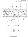
図1〜2に示されるように、本発明の一実施の形態にかかわる押出機は、シリンダー1、該シリンダー1内に収納されるスクリュー2、ベースコンパウンドを供給する材料供給手段A、前記スクリュー2により搬送され、可塑化されたベースコンパウンドに薬品を供給する薬品供給手段Bおよび可塑化されたベースコンパウンドの搬送流量を調節する流量調節手段Cとから構成されている。前記材料供給手段Aは、スクリュー2の上流側のスクリュー尾端3近傍に設置されており、この材料供給手段Aとしては、通常用いられる供給ホッパーを用いることができる。
【0012】
前記スクリュー2は、単軸スクリューである。前記流量調節手段Cは、このスクリュー2の下流側に設けられている。前記材料供給手段Aの供給口4から供給されたベースコンパウンドは、この流量調節手段Cまでスクリュー2により搬送されるあいだに可塑化される(可塑化域S1)とともに、加圧される(加圧域S2)。そして、流量調節手段Cにより所定の搬送量が調節され、つぎの領域へと押し出される。この流量調節手段Cからスクリュー2の先端までの寸法は3〜5Dとする。なお、このスクリュー2の形状や寸法は適宜選定することができるが、本実施の形態では、リード長が0.8〜1.3Dの2条ねじにされているとともに、谷径が0.52〜0.78Dに設定されている。これは谷径が0.52D未満であると、スクリュー2の捩じり強度が不足し、0.78Dをこえると、搬送量が少なくなるからである。
【0013】
前記流量調節手段Cとしては、フライトの外周に可塑化されたベースコンパウンドを通過させる複数の浅い溝を設けた堰を用いることができる。本実施の形態では、流量調節手段Cとして、2つのフライトの外周に溝がそれぞれ設けられた2段形状の堰を採用している。この堰は、ベースコンパウンドの堰通過量(搬送量)と圧力とが密接な関係があるので、常に一定圧力に保持できるように設けられている。スクリュー尾端2aからこの堰までの距離L1は、ベースコンパウンドの物性により異なるが、混練に必要な可塑性を与え、堰通過量を一定に保ちながら加圧するために、4D以上であるとともに、長すぎると発熱により効率が低下するため、16D以下に設定する。すなわち距離L1は4〜16Dとするのが好ましい。堰の幅は、短いとニーダー効果が減少し、分散性が低下するとともに、長いと通過抵抗により、堰通過量が低下するため、5〜40mmであるのが好ましい。また、この堰の溝角は、スクリュー軸に対して5〜35°傾斜している。これは溝角が5°未満であると、堰通過量のばらつきが大きくなり配合比が変動し、35°をこえると通過抵抗が増加し、堰通過量が低下するためである。また、堰の溝断面は、半円または楕円形状を呈しており、溝断面積は、1.5〜12mm2である。これは溝断面積が1.5mm2未満でも分散性の向上はみられないとともに、堰通過量が急激に減少し、12mm2をこえると分散性がわるくなるためである。さらに隣接する溝間の陸部の幅は、1.5〜3.5mmである。これは1.5mm未満では分散性がわるくなり、3.5mmをこえると堰通過量が低下するためである。
【0014】
前記薬品供給手段(仕上薬品の添加手段)Bは、ベースコンパウンドが可塑化された位置において、前記流量調節手段Cよりスクリュー2の上流側に設けられ、一定量の仕上薬品をスクリュー2の溝に連続して注入することができるものであれば、本発明においては、とくに限定されるものではない。すなわち材料供給手段Aであるホッパーからスクリュー2の中間部までは、ベースコンパウンドが充分に可塑化されておらず、材料供給量の変動により、搬送量が一定していないので、充分に可塑化された状態で、搬送量および圧力が安定した位置において、仕上練用薬品またはそのマスターバッチを供給するものであり、コンパウンドおよび添加する薬品の特性や量により適宜選定することができる。かかる薬品供給手段Bとして、本実施の形態では、シリンダー1に挿通される円筒形の薬品供給ピン11と、薬品供給ピン11に薬品を送り込む薬品送出し手段12、たとえば垂直スクリューフィーダと、薬品供給ピン11と薬品送出し手段12とのあいだに設置される、たとえば2軸ギアポンプ13とから構成されるものが用いられている。かかる2軸ギアポンプ13を介在させて、薬品送出し手段12の供給口14から供給されたマスターバッチを可塑化し、加圧させながら、前記薬品供給ピン11からスクリュー溝へ一定量の薬品を連続注入する。図1〜2において、5はフライト(螺旋)2aに形成される薬品供給ピン11の通過溝である。本実施の形態では、この薬品供給ピン11を周上に1箇所設けているが、本発明においては、これに限定されるものではなく、薬品供給ピン11を、少なくともスクリュー尾端3より2.5Dの位置から流量調節手段Cの堰まで、たとえば図1に示されるように、所定の範囲Pの1リードごとに4〜8箇所を放射状に配列することができる。
【0015】
なお、本実施の形態では、2軸ギアポンプ13により加圧して注入しているが、本発明においては、マスターバッチコンパウンドが、押出機で充分加圧され、一定量を連続的に供給できる条件が満足されるなら、かかる2軸ギアポンプ13を省いて直接薬品供給としてマスターバッチを注入することもできる。また、前記薬品供給ピン11とともに、薬品注入に使用されないピンを隣接して設けると、薬品供給ピン11から薬品を注入した直後、隣接するピンでスクリュー溝中でのコンパウンドの練り返し作用により、マクロ的に添加物をコンパウンド中に分散させることもできる。
【0016】
前記堰を通過したコンパウンドは、可塑化されているので、次工程に必要なシート状の中間製品にするため、フローチャンネル(スクリュー先端からダイに到るまでのコンパウンドの流路)に取り付けられた口金を介して押し出される。この口金の断面積は、概ねシリンダーの断面積の10〜40%とするのが、押出機の効率の向上および製品の寸法安定上望ましい。コンパウンドを口金を介して押し出すためには、コンパウンドを加圧する必要があり、かかる加圧域として、図1に示されるように、堰からの長さL2(3〜5D)のスクリュー部分が設けられている。
【0017】
さらに、スクリューの先端にギアポンプを配置するとともに、このギアポンプの先端に口金を取り付けることにより、搬送量がさらに安定し、一定温度のコンパウンドを正確に一定量押し出すことができる。なお、コンパウンドの温度は、スクリューとシリンダーの温度制御、スクリューの回転数と口金の断面積(先端圧力)の設定値およびコンパウンドの粘度の関係から、容易に一定温度に保つことができる。また、口金の断面積がシリンダーの断面積の10%より少なくなっても、該押出機先端にギアポンプも取り付ければ、ギアポンプの特性上押出機の排出量に影響することなくコンパウンドを押し出すことができるので、高粘度のコンパウンドなどにはとくに有効である。また、口金の抵抗が押出機に作用しないので、直接、必要な中間製品を押し出すことができる。同時にメッシュスクリーンを入れても、押出機に負荷がかからないので、中間製品の最終段階で異物を除去することができる。
【0018】
つぎに他の薬品供給手段B1を用いた本発明の他の実施の形態を説明する。本実施の形態における薬品供給手段B1は、図3に示されるように、薬品供給ピン21に接続されるギアポンプ22およびギアポンプ22に配管接続される調圧のためのサージタンク23とから構成されている。本実施の形態における薬品供給手段B1は、前記薬品供給手段Bと同様にスクリュー2の所定の範囲Pに適宜配列させることができる。図3において、24はモータおよび回転羽根からなる撹拌手段である。本実施の形態では、前記サージタンク22により、薬品とオイルを混合し、液状にして薬品供給ピン21から一定量連続して注入することができる。
【0019】
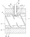
つぎにさらに他の薬品供給手段B2を用いた本発明の他の実施の形態を説明する。本実施の形態における薬品供給手段B2は、図4に示されるように、薬品供給ピン31に配置された固形物32をアクチュエータに連結されるピストン33でスクリュー2の溝に押し込める薬品送出し手段(図示せず)から構成されている。本実施の形態における薬品供給手段B2は、前記薬品供給手段Bと同様にスクリュー2の所定の範囲Pに適宜配列させることができる。前記固形物32は、高級脂肪酸またはワックスに溶解または分散させたものである。本実施の形態では、前記薬品供給ピン31の供給口34から挿入された固形物32を該薬品供給ピン31を配列した個所から、一定量をピストン33で連続してスクリュー2の溝に押し込み可塑化されたベースコンパウンドに添加する。なお、図4において、35は加圧された固形物32をスクリュー溝内で摺りつぶす(粉砕する)凹凸溝である。
【0020】
なお、本実施の形態は、堰を1箇所設けるようにしているが、本発明においては、当該第1堰より下流側に第2堰を設けることもできる。この第2堰を設ける場合は、第1堰(流量調整手段Cである堰)直後の1リード内のスクリュー溝は、コンパウンドで完全に充填されていないので、圧力は加えられていないとともに、コンパウンドの表面積も最大になっているので、大気圧下で、小粒状、粉末または液状の他の薬品の添加を行なうことができる。したがって、他の薬品供給としてマスターバッチを供給するときには、ホッパーの供給口から直接供給することができる。また、図1に示されるように、第1堰(流量調整手段Cである堰)直後で、真空ポンプ器41により減圧すると、ベント押出機と同様に揮発物を抜気できるので、発泡の少ない緻密な中間製品を得ることができる。
【0021】
前記第2堰を設ける場合、第1堰から3〜6Dの位置に設け、溝角は第1堰とほぼ等しくするととに、溝数および溝断面積は第1堰と等しいか、または大きくする。第1堰から第2堰までのスクリュー長は、すでにベースコンパウンドが可塑化されているため、第2堰を通過させるための加圧に必要な長さで充分であるから、3〜6Dとする。また、第2堰の幅は、短いとニーダー効果が減少し、分散性がわるくなり、長いと通過抵抗の増大により搬送量が低下するため、5〜40mmとするのが好ましい。また、この第2堰からスクリュー先端までの加圧域は3〜5Dになるように設定する。
【0022】
また、薬品をオイルに溶解もしくは分散したり、または混合した薬品を加温液化もしくはペースト状にして、スクリュー溝中に注入する方法では、所定の薬品を注入することができるスクリュー軸長さ方向に限界がある。これは、ベースコンパウンドの種類にも依存するが、油脂類が多いと、スクリューまたはシリンダー壁が部分的に油脂類で濡らされ、配合物とのあいだで滑りが生じるためであり、その結果、スクリューの搬送量が変動し、薬品が定量的に注入されても、配合比が変動する。
【0023】
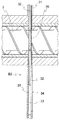
そこで、このような配合比の変動をなくすため、本発明の他の実施の形態の押出機では、液状薬品をシリンダ1内に直接添加するために、図5に示されるように、先端が閉じられた薬品供給ピン51の側面に形成された注入口51aが、スクリュー2の回転方向(図5に示されるスクリューは、注入口が配置されているスクリューの上部が図において手前側にくるように回転する)に向いて開口しており、かつ、注入口51aが、スクリュー2の谷2aから注入口51aの中心位置までの距離Yがスクリュー2の山2bの高さHの0.3〜0.8倍程度になるように、配置されている。
【0024】
薬品供給ピン51は、中空の調節ネジ52に嵌合された状態でシリンダ1の貫通孔1aを通してシリンダ1内に挿入されている。また、シリンダ1の外側面であって、貫通孔1aの外側開口の周囲には、ナット53が固着されている。調節ネジ52はナット53に螺合されているため、調節ネジ52を回転させることにより、薬品供給ピン51および調節ネジ52の高さを変更することができる。
【0025】
シリンダ1内では、図5に示されるように、薬品供給ピン51の周辺に渦流Vが生じるが、薬品供給ピン51の注入口51aを、スクリュー2の谷2aから山2bの高さHの0.3〜0.8倍程度の位置において回転方向側に向いているので、該注入口51a付近に発生する渦流V内部の低圧力部Pに薬品を注入することができる。それにより、混合効果を高め、スクリューシリンダー1の壁の漏れを防止することができる。
【0026】
なお、薬品は、前記実施の形態と同様に、ギアポンプを介して加圧しながら供給する。また、注入される薬品は、前記実施の形態と同様に、オイルを混合した液状にした液状分散薬品などが用いられる。
【0027】
さらに、調節ネジ52を回転させて薬品供給ピン51の注入口51aの高さを変えることにより、スクリュー溝2c中の旋回流Vと推進流Wの境界層に注入することができ、その結果、混合効果を高め、シリンダ壁の濡れを防止することができる。
【0028】
なお、これまでの実施の形態では、薬品供給としてマスターバッチを可塑化し、圧入するか、薬品とオイルとの混合液を圧入するか、または固形成型した薬品を圧入しているが、本発明においては、これらのうち、少なくとも2種類を組合せて圧入することもできる。
【0029】
【発明の効果】
以上説明したとおり、本発明によれば、ベースコンパウンドと薬品が同じ比率で押出機内に供給されるとともに、均一なゴム配合物を得ることができる。
【図面の簡単な説明】
【図1】本発明の押出機の一実施の形態におけるスクリューを示す側面図である。
【図2】本発明における薬品供給手段の一実施例を示す要部断面図である。
【図3】本発明における薬品供給手段の他の実施例を示す側面図である。
【図4】本発明における薬品供給手段のさらに他の実施例を示す要部断面図である。
【図5】本発明における薬品供給手段のさらに他の実施例を示す要部断面図である。
【符号の説明】
1 シリンダー
2 スクリュー
2a フライト(螺旋)
3 スクリュー尾端
4、14、34 供給口
5 通過溝
11、21、31、51 薬品供給ピン
12 薬品送出し手段
13 2軸ギアポンプ
22 ギアポンプ
23 サージタンク
24 撹拌手段
32 固形物
33 ピストン
35 凹凸溝
41 真空ポンプ器
52 調節ネジ
53 ナット
A 材料供給手段
B、B1、B2 薬品供給手段
C 流量調節手段[0001]
TECHNICAL FIELD OF THE INVENTION
The present invention relates to a screw extruder and an extrusion method. More specifically, for example, a screw extruder that extrudes a plasticized rubber kneaded material composed of rubber and chemicals with a screw, or a vent extrusion having a vent area for releasing the pressure in a screw groove until extruded. The present invention relates to an extruder such as an extruder and an extrusion method.
[0002]
[Prior art]
As a conventional extruder, a material supply hopper and a chemical supply hopper are installed in a screw extruder in which a screw is housed in a cylinder, and an extruder comprising a rubber supply step, a chemical supply step, a kneading step, and a compression (pressure) step is formed. Extruded material (hereinafter referred to as “base compound”) in which a reinforcing agent and a filler are kneaded in advance with a polymer, and a vulcanization accelerator and oils and fats for maintaining physical properties after vulcanization and vulcanization. There is one that continuously and quantitatively mixes with such a chemical (see Patent Documents 1 and 2). In such a rubber kneader, a weir is provided between the screw in the rubber supply step and the screw in the chemical supply step in order to adjust the amount of rubber transported per rotation of the screw.
[0003]
The base compound supplied from the material supply hopper in such an extruder is extruded by receiving a conveying force from a flight (spiral) by rotating a screw, and proceeds while being plasticized to a weir. Then, a certain amount of a continuously plasticized base compound passes from the weir, and a certain amount of the chemical is continuously supplied to the base compound. Further, they are mixed well in a kneading step, conveyed to a compression step necessary for extrusion, and extruded (discharged) from the tip.
[0004]
[Patent Document 1]
Japanese Patent Application Laid-Open No. 10-71615 [Patent Document 2]
JP 2000-52334 A [0005]
[Problems to be solved by the invention]
However, due to the difference in shear resistance and the difference in adhesion between the cylinder and the screw due to the mixing and blending of the base compound and the chemical and the temperature control conditions, the base compound and the chemical are uniformly supplied and mixed in the extruder at the same ratio. There is a problem that it is not always true.
[0006]
In view of the circumstances described above, an object of the present invention is to provide an extruder and an extrusion method, in which a base compound and a chemical are supplied into an extruder at the same ratio, and a uniform rubber compound can be obtained. I do.
[0007]
[Means for Solving the Problems]
The extruder of the present invention is an extruder that accommodates a screw in a cylinder and extrudes a plasticized material to be extruded, and is provided upstream of the screw and supplies material to be extruded. And a chemical supply means for supplying a chemical to the plasticized material to be extruded, which is conveyed by the screw, and a flow rate adjusting means for adjusting the conveyance flow rate of the plasticized material to be extruded on the downstream side of the screw. The chemical supply means includes a cylindrical chemical supply pin provided at a position where the material to be extruded is plasticized, on the upstream side of the screw from the flow rate adjusting means.
[0008]
Further, in the extrusion method of the present invention, a screw in which a flow rate adjusting means for adjusting a transport flow rate of a plasticized material to be extruded is housed in a cylinder, and the plasticized material to be extruded is extruded. In the extrusion method, the medicine is supplied from a cylindrical medicine supply pin provided at a position where the material to be extruded is plasticized on the upstream side of the screw from the flow rate adjusting means.
[0009]
BEST MODE FOR CARRYING OUT THE INVENTION
In the present invention, as a chemical, a master batch obtained by kneading a polymer and necessary additive chemicals is plasticized and press-fitted, or a mixed liquid of a drug and an oil is press-fitted, or a solid-formed drug is press-fitted, or these are press-fitted. Of these, at least two types are combined and press-fitted. When adding a chemical to the plasticized base compound, in order to mix uniformly in the screw groove, there is an optimum position for adding the chemical (position in the screw axis direction) due to the characteristics of both. That is, even if the chemicals are added to the base compound from the same position, they are not mixed at the same ratio. For this reason, plasticization progresses, and the screw groove is completely filled with the base compound. At least 2.5D (D: outer diameter of the screw) from the tail end of the screw to the radial direction for each lead from the position to the flow control means. The medicine is supplied from the medicine supply pins arranged in the column. The drug supply pin has a cylindrical shape (hollow shape) and is connected to the outside. A master batch, a mixed solution, or a solid (mixture) of the drug is injected from an optimum position through the drug supply pin. . In addition, if a pin not used for drug injection is provided adjacent to the drug supply pin, immediately after the drug is injected from the drug supply pin, the compound is turned back by the adjacent pin in the screw groove (in the screw groove). By disturbing the flow direction of the compound, the effect of enhancing the mixing effect can be dispersed macroscopically. When such a compound (which has already been added with a chemical) passes through the groove of the flow control means, it is finely divided and crushed between the cylinder wall, so that the added chemical is finely and uniformly mixed.
[0010]
Hereinafter, an extruder and an extrusion method of the present invention will be described with reference to the accompanying drawings.
[0011]
As shown in FIGS. 1 and 2, an extruder according to one embodiment of the present invention includes a cylinder 1, a screw 2 housed in the cylinder 1, a material supply unit A for supplying a base compound, And a flow rate adjusting means C for adjusting the conveying flow rate of the plasticized base compound by supplying a chemical to the plasticized base compound. The material supply means A is installed near the screw tail end 3 on the upstream side of the screw 2. As the material supply means A, a commonly used supply hopper can be used.
[0012]
The screw 2 is a single screw. The flow rate adjusting means C is provided downstream of the screw 2. The base compound supplied from the supply port 4 of the material supply means A is plasticized while being conveyed by the screw 2 to the flow rate control means C (plasticized area S1), and is pressurized (pressurized). Area S2). Then, the predetermined transport amount is adjusted by the flow rate adjusting means C, and is extruded to the next area. The dimension from the flow control means C to the tip of the screw 2 is 3 to 5D. The shape and size of the screw 2 can be appropriately selected. In the present embodiment, the screw length is 0.8 to 1.3D and the root diameter is 0.52. It is set to 0.78D. This is because when the valley diameter is less than 0.52D, the torsional strength of the screw 2 becomes insufficient, and when it exceeds 0.78D, the transport amount decreases.
[0013]
As the flow rate adjusting means C, a weir provided with a plurality of shallow grooves for allowing the plasticized base compound to pass through the periphery of the flight can be used. In this embodiment, a two-stage weir in which grooves are provided on the outer periphery of two flights is adopted as the flow rate adjusting means C. This weir is provided so that the amount of passage of the base compound (the amount of conveyance) and the pressure are closely related, so that the pressure can always be maintained at a constant pressure. The distance L1 from the screw tail end 2a to the weir depends on the physical properties of the base compound, but is 4D or more and too long to provide the plasticity necessary for kneading and to pressurize the weir while keeping it constant. Since the efficiency is reduced due to heat generation, it is set to 16D or less. That is, the distance L1 is preferably set to 4 to 16D. If the width of the weir is short, the kneader effect is reduced and the dispersibility is reduced, and if the width is long, the passage amount of the weir is reduced due to the passage resistance. The groove angle of this weir is inclined at 5 to 35 ° with respect to the screw axis. This is because when the groove angle is less than 5 °, the variation in the weir passage amount increases and the mixing ratio fluctuates. When the groove angle exceeds 35 °, the passage resistance increases and the weir passage amount decreases. Further, the groove cross section of the weir has a semicircular or elliptical shape, and the groove cross sectional area is 1.5 to 12 mm 2 . This is because the dispersibility is not improved even when the groove cross-sectional area is less than 1.5 mm 2 , and the amount of passage through the weir decreases sharply, and when the groove cross section exceeds 12 mm 2 , the dispersibility deteriorates. Further, the width of the land between the adjacent grooves is 1.5 to 3.5 mm. This is because the dispersibility becomes poor when the thickness is less than 1.5 mm, and the weir passage amount decreases when the thickness exceeds 3.5 mm.
[0014]
The chemical supply means (finish chemical addition means) B is provided upstream of the screw 2 from the flow rate control means C at a position where the base compound is plasticized, and a certain amount of the finish chemical is inserted into the groove of the screw 2. The present invention is not particularly limited as long as it can be continuously injected. That is, from the hopper, which is the material supply means A, to the intermediate portion of the screw 2, the base compound is not sufficiently plasticized, and the transport amount is not constant due to the fluctuation of the material supply amount. In this state, the finishing kneading chemical or its master batch is supplied at a position where the transport amount and the pressure are stable, and can be appropriately selected according to the properties and the amount of the compound and the added chemical. In the present embodiment, as the medicine supply means B, in the present embodiment, a cylindrical medicine supply pin 11 inserted into the cylinder 1, a medicine delivery means 12 for delivering the medicine to the medicine supply pin 11, for example, a vertical screw feeder, For example, a two-axis gear pump 13 which is provided between the pin 11 and the medicine delivery means 12 is used. With the biaxial gear pump 13 interposed, the masterbatch supplied from the supply port 14 of the medicine delivery means 12 is plasticized, and a certain amount of medicine is continuously injected from the medicine supply pin 11 into the screw groove while pressurizing. I do. In FIGS. 1 and 2, reference numeral 5 denotes a passage groove for the medicine supply pin 11 formed on the flight (spiral) 2a. In the present embodiment, the chemical supply pin 11 is provided at one place on the circumference, but the present invention is not limited to this. From the position 5D to the weir of the flow rate adjusting means C, for example, as shown in FIG. 1, 4 to 8 locations can be radially arranged for each lead in a predetermined range P.
[0015]
In the present embodiment, the injection is performed under pressure by the two-shaft gear pump 13. However, in the present invention, the conditions under which the master batch compound is sufficiently pressurized by an extruder and a constant amount can be continuously supplied. If satisfied, the masterbatch can be injected as a direct chemical supply, omitting such a twin-shaft gear pump 13. In addition, if a pin that is not used for drug injection is provided adjacently along with the drug supply pin 11, immediately after the drug is injected from the drug supply pin 11, the adjacent pin will cause the compound to be remixed in the screw groove by the macro pin. Additives can also be dispersed throughout the compound.
[0016]
Since the compound that passed through the weir was plasticized, it was attached to a flow channel (compound flow path from the screw tip to the die) in order to form a sheet-like intermediate product required for the next step. Extruded through the base. It is desirable that the cross-sectional area of the die is approximately 10 to 40% of the cross-sectional area of the cylinder in order to improve the efficiency of the extruder and stabilize the dimensions of the product. In order to extrude the compound through the base, it is necessary to pressurize the compound. As such a pressurized area, a screw portion having a length L2 (3 to 5D) from the weir is provided as shown in FIG. ing.
[0017]
Further, by disposing a gear pump at the tip of the screw and attaching a base to the tip of the gear pump, the transport amount can be further stabilized, and a constant temperature compound can be accurately extruded. The temperature of the compound can be easily maintained at a constant temperature by controlling the temperature of the screw and the cylinder, the set value of the rotation speed of the screw and the cross-sectional area (tip pressure) of the die, and the viscosity of the compound. Even if the cross-sectional area of the base is smaller than 10% of the cross-sectional area of the cylinder, the compound can be extruded without affecting the output of the extruder due to the characteristics of the gear pump if a gear pump is attached to the extruder tip. Therefore, it is particularly effective for high viscosity compounds. Also, since the resistance of the die does not act on the extruder, the required intermediate product can be extruded directly. Even if the mesh screen is put in at the same time, since no load is applied to the extruder, foreign substances can be removed at the final stage of the intermediate product.
[0018]
Next, another embodiment of the present invention using another chemical supply means B1 will be described. As shown in FIG. 3, the medicine supply means B1 in the present embodiment includes a gear pump 22 connected to the medicine supply pin 21 and a surge tank 23 for pressure regulation connected to the gear pump 22 by piping. I have. The medicine supply means B1 in the present embodiment can be appropriately arranged in a predetermined range P of the screw 2 similarly to the medicine supply means B. In FIG. 3, reference numeral 24 denotes a stirring means comprising a motor and rotating blades. In the present embodiment, the surge tank 22 can mix the medicine and the oil, make them liquid, and continuously inject a certain amount from the medicine supply pin 21.
[0019]
Next, another embodiment of the present invention using still another chemical supply means B2 will be described. As shown in FIG. 4, the medicine supply means B2 in the present embodiment is a medicine delivery means for pushing a solid substance 32 arranged on a medicine supply pin 31 into a groove of the screw 2 by a piston 33 connected to an actuator. (Not shown). The medicine supply means B2 in the present embodiment can be appropriately arranged in a predetermined range P of the screw 2 similarly to the medicine supply means B. The solid substance 32 is dissolved or dispersed in a higher fatty acid or wax. In the present embodiment, a certain amount of the solid substance 32 inserted from the supply port 34 of the medicine supply pin 31 is continuously pushed into the groove of the screw 2 by the piston 33 from the place where the medicine supply pin 31 is arranged. To the formulated base compound. In FIG. 4, reference numeral 35 denotes an uneven groove for crushing (crushing) the pressurized solid substance 32 in the screw groove.
[0020]
In this embodiment, one weir is provided, but in the present invention, a second weir may be provided downstream of the first weir. In the case where the second weir is provided, the screw groove in one lead immediately after the first weir (the weir serving as the flow rate adjusting means C) is not completely filled with the compound. Has the maximum surface area, so that addition of other chemicals in the form of small particles, powders or liquids can be performed under atmospheric pressure. Therefore, when the master batch is supplied as another chemical supply, it can be supplied directly from the supply port of the hopper. Also, as shown in FIG. 1, when the pressure is reduced by the vacuum pump 41 immediately after the first weir (the weir serving as the flow rate adjusting means C), volatile substances can be removed similarly to the vent extruder. A dense intermediate product can be obtained.
[0021]
When the second weir is provided, the second weir is provided at a position 3 to 6D from the first weir, the groove angle is substantially equal to the first weir, and the number of grooves and the groove cross-sectional area are equal to or larger than the first weir. . The screw length from the first weir to the second weir is 3 to 6D because the base compound is already plasticized and the length required for pressurization to pass through the second weir is sufficient. . Further, the width of the second weir is preferably 5 to 40 mm because the kneader effect decreases when the width is short, and the dispersibility becomes poor. The pressure range from the second weir to the screw tip is set to 3 to 5D.
[0022]
In addition, in the method of dissolving or dispersing a drug in oil, or heating and liquefying or mixing a mixed drug, and injecting it into a screw groove, a predetermined drug can be injected in a screw shaft length direction. There is a limit. This depends on the type of base compound, but if there is a lot of fats and oils, the screw or cylinder wall will be partially wetted by the fats and oils and slip will occur between the compound and as a result, the screw Even if the transported amount of the medicine fluctuates and the medicine is quantitatively injected, the mixing ratio fluctuates.
[0023]
Therefore, in order to eliminate such a change in the mixing ratio, in the extruder according to another embodiment of the present invention, the tip is closed as shown in FIG. The injection port 51a formed on the side surface of the medicine supply pin 51 is connected to the rotation direction of the screw 2 (the screw shown in FIG. 5 is such that the upper part of the screw on which the injection port is arranged is located on the near side in the figure). And the distance Y from the valley 2a of the screw 2 to the center position of the inlet 51a is 0.3 to 0 of the height H of the crest 2b of the screw 2. It is arranged so as to be about .8 times.
[0024]
The chemical supply pin 51 is inserted into the cylinder 1 through the through hole 1a of the cylinder 1 in a state fitted to the hollow adjustment screw 52. A nut 53 is fixed on the outer surface of the cylinder 1 around the outer opening of the through hole 1a. Since the adjusting screw 52 is screwed to the nut 53, the height of the medicine supply pin 51 and the adjusting screw 52 can be changed by rotating the adjusting screw 52.
[0025]
In the cylinder 1, as shown in FIG. 5, a vortex V is generated around the drug supply pin 51, but the injection port 51 a of the drug supply pin 51 is moved from the valley 2 a of the screw 2 to the height H of the peak 2 b by Since it is turned to the rotation direction side at a position of about 3 to 0.8 times, it is possible to inject the chemical into the low pressure part P inside the vortex V generated near the injection port 51a. Thereby, the mixing effect can be enhanced, and leakage of the wall of the screw cylinder 1 can be prevented.
[0026]
The chemical is supplied while being pressurized via a gear pump, as in the above embodiment. As the chemical to be injected, a liquid dispersion chemical in which oil is mixed is used as in the above embodiment.
[0027]
Further, by rotating the adjusting screw 52 to change the height of the injection port 51a of the drug supply pin 51, the injection can be performed into the boundary layer between the swirling flow V and the propulsion flow W in the screw groove 2c. The mixing effect can be enhanced, and wetting of the cylinder wall can be prevented.
[0028]
In the embodiments described above, the masterbatch is plasticized as a chemical supply, and the masterbatch is press-fitted, the mixed liquid of the drug and the oil is pressed, or the solid-formed drug is pressed, but in the present invention, Can be press-fitted by combining at least two of them.
[0029]
【The invention's effect】
As described above, according to the present invention, the base compound and the chemical are supplied into the extruder at the same ratio, and a uniform rubber compound can be obtained.
[Brief description of the drawings]
FIG. 1 is a side view showing a screw in an embodiment of an extruder of the present invention.
FIG. 2 is a sectional view of a main part showing an embodiment of a medicine supply means in the present invention.
FIG. 3 is a side view showing another embodiment of the medicine supply means in the present invention.
FIG. 4 is a cross-sectional view of a main part showing still another embodiment of the medicine supply means in the present invention.
FIG. 5 is a sectional view of a main part showing still another embodiment of the medicine supply means in the present invention.
[Explanation of symbols]
1 cylinder 2 screw 2a flight (spiral)
3 Screw tail end 4, 14, 34 Supply port 5 Passage groove 11, 21, 31, 51 Chemical supply pin 12 Chemical delivery means 13 Two-axis gear pump 22 Gear pump 23 Surge tank 24 Stirring means 32 Solid matter 33 Piston 35 Irregular groove 41 Vacuum pump 52 Adjustment screw 53 Nut A Material supply means B, B1, B2 Chemical supply means C Flow rate adjustment means