JP2004237450A - Ink jet recorder and its controlling method - Google Patents
Ink jet recorder and its controlling method Download PDFInfo
- Publication number
- JP2004237450A JP2004237450A JP2003025779A JP2003025779A JP2004237450A JP 2004237450 A JP2004237450 A JP 2004237450A JP 2003025779 A JP2003025779 A JP 2003025779A JP 2003025779 A JP2003025779 A JP 2003025779A JP 2004237450 A JP2004237450 A JP 2004237450A
- Authority
- JP
- Japan
- Prior art keywords
- ink
- recording
- operation mode
- remaining amount
- amount
- Prior art date
- Legal status (The legal status is an assumption and is not a legal conclusion. Google has not performed a legal analysis and makes no representation as to the accuracy of the status listed.)
- Withdrawn
Links
Images


Classifications
-
- B—PERFORMING OPERATIONS; TRANSPORTING
- B41—PRINTING; LINING MACHINES; TYPEWRITERS; STAMPS
- B41J—TYPEWRITERS; SELECTIVE PRINTING MECHANISMS, i.e. MECHANISMS PRINTING OTHERWISE THAN FROM A FORME; CORRECTION OF TYPOGRAPHICAL ERRORS
- B41J29/00—Details of, or accessories for, typewriters or selective printing mechanisms not otherwise provided for
- B41J29/38—Drives, motors, controls or automatic cut-off devices for the entire printing mechanism
-
- B—PERFORMING OPERATIONS; TRANSPORTING
- B41—PRINTING; LINING MACHINES; TYPEWRITERS; STAMPS
- B41J—TYPEWRITERS; SELECTIVE PRINTING MECHANISMS, i.e. MECHANISMS PRINTING OTHERWISE THAN FROM A FORME; CORRECTION OF TYPOGRAPHICAL ERRORS
- B41J2/00—Typewriters or selective printing mechanisms characterised by the printing or marking process for which they are designed
- B41J2/005—Typewriters or selective printing mechanisms characterised by the printing or marking process for which they are designed characterised by bringing liquid or particles selectively into contact with a printing material
- B41J2/01—Ink jet
- B41J2/17—Ink jet characterised by ink handling
- B41J2/175—Ink supply systems ; Circuit parts therefor
- B41J2/17503—Ink cartridges
- B41J2/17506—Refilling of the cartridge
- B41J2/17509—Whilst mounted in the printer
-
- B—PERFORMING OPERATIONS; TRANSPORTING
- B41—PRINTING; LINING MACHINES; TYPEWRITERS; STAMPS
- B41J—TYPEWRITERS; SELECTIVE PRINTING MECHANISMS, i.e. MECHANISMS PRINTING OTHERWISE THAN FROM A FORME; CORRECTION OF TYPOGRAPHICAL ERRORS
- B41J2/00—Typewriters or selective printing mechanisms characterised by the printing or marking process for which they are designed
- B41J2/005—Typewriters or selective printing mechanisms characterised by the printing or marking process for which they are designed characterised by bringing liquid or particles selectively into contact with a printing material
- B41J2/01—Ink jet
- B41J2/17—Ink jet characterised by ink handling
- B41J2/175—Ink supply systems ; Circuit parts therefor
- B41J2/17566—Ink level or ink residue control
-
- B—PERFORMING OPERATIONS; TRANSPORTING
- B41—PRINTING; LINING MACHINES; TYPEWRITERS; STAMPS
- B41J—TYPEWRITERS; SELECTIVE PRINTING MECHANISMS, i.e. MECHANISMS PRINTING OTHERWISE THAN FROM A FORME; CORRECTION OF TYPOGRAPHICAL ERRORS
- B41J29/00—Details of, or accessories for, typewriters or selective printing mechanisms not otherwise provided for
- B41J29/02—Framework
Landscapes
- Ink Jet (AREA)
Abstract
Description
【0001】
【発明の属する技術分野】
本発明はインクを吐出して記録媒体上に画像を記録するインクジェット記録装置に関するものである。本発明は特に、インクジェット記録装置に取り外し可能に装着されるインクタンクの、インクの残量検出、またはインク残量管理システムに関するものである。
【0002】
【従来の技術】
インクジェット技術を用いた記録装置(以下、印刷装置ともいう)で、発熱体(ヒータ)を記録素子として用い、インクを発熱体が発生する熱エネルギーにより気化させ、その際にインク中に発生する気泡の膨張力でインクを吐出するバブルジェット(R)方式のインクジェット記録装置が知られている。
【0003】
このインクジェット方式の記録装置においては、インクがなくなった状態でインクの吐出を行わせて記録動作を実行した場合、記録ヘッドは気化熱による冷却効果が期待できなくなり、そのインクが無い状態のまま記録ヘッドの駆動を続けた場合、記録ヘッドの発熱体がダメージを受け、吐出に十分な熱エネルギーを発生できなくなったり、または、発熱体が断線するという不具合が発生するおそれがある。
【0004】
このような不具合を避けるため、インクタンクに電気的に消去書込が可能な電気素子(以下EEPROM)を設けて、インクの残量を管理する方法が実用化されている。
【0005】
このインク残量の管理は、インクの消費に伴い、消費分だけ、インクの残量あるいは消費量を常にEEPROMに書込むことによって、使用したインク量、もしくはインクタンクに残るインク量を管理するものである。この方法としては、具体的には、画像データによって吐出されるインク量を予測したり、画像データによって吐出されるドット数をカウントしたり、もしくは吐出用の発熱体を駆動した回数を直接カウントする方法などがある。
【0006】
このようなインク残量の管理によって、例えば、インクの残量を示す値がゼロになった場合には記録動作を禁止することにより、印字ヘッドが発熱によりダメージをうけるのを未然に防ぐことができる。
【0007】
また、記録剤の残量の管理に関する発明を開示する特許文献1には、トナーが無くなった場合に画像形成を禁止し、その後にトナーが補給されたか否かを確実に判定することで、画像形成の禁止を正しく解除できるようにした構成が記載されている。また、特許文献2には、インク残量を用いて記録可能な枚数の管理を行うとともに、インクの無くなったインクタンクが新たなインクタンクと交換されるまで画像記録を停止させるようにした構成が記載されている。
【0008】
【特許文献1】
特開平05−181364号公報
【特許文献2】
特開平07−025030号公報
【0009】
【発明が解決しようとする課題】
前述のインク残量管理を行うことで、インクがなくなった場合に、印字動作の停止を行えば記録ヘッドがダメージをうけるのを防止することができる。
【0010】
しかしながら、実際に吐出されるインクの量にはわずかなばらつきがあったり、環境条件によって吐出されるインク量にばらつきが生じたりすることがあり、管理上のインク残量がゼロとなる前に実際のインク残量がゼロとならないようにするため、管理上のインク残量の方がわずかながら早めにゼロとなるように管理することが考えられる。つまり、管理上のインク残量がゼロとなる前に記録が行えない状態となることはユーザの利便性を考えると不適切であり、また、記録ヘッドの損傷を防止するために、管理上のインク残量を実際のインク残量よりも少なめに管理し、実際にインクが無くなる前に、管理上ではインク残量がゼロとなるようにすることで、ユーザへインクタンクの交換を促し、記録ヘッドの損傷を防止するよう構成されていることが一般的である。
【0011】
このような構成の場合、管理上はインク残量がゼロとなった時の実際のインク残量は、前述のような要因によってばらつきがあり、数ページ程度の印字を行える程度にインクが残っていることも想定される。また、記録動作の途中で管理上のインク残量がゼロとなったとしても、その記録動作を継続させることで、記録中の記録用紙の無駄を防止する必要もある。そのために、管理上のインク残量がゼロとなった場合においても、記録動作を続行させたり、ユーザにより記録動作の指示に応じて記録動作を実行可能にすることが、設計上では望まれる仕様である。
【0012】
上記のように、インク残量がゼロとなった場合においても記録動作を可能とすることでランニングコストを低減でき、ユーザの利便性が向上するが、無制限に記録動作を可能とした場合、実際のインク残量がゼロとなってしまい、問題が生じてしまう。
【0013】
また、管理上のインク残量がゼロとなった後も継続的に記録動作を可能とするように、ユーザ自身の責任の下でインクの供給系が改造されることも想定されるが、この場合はインク供給系からのインクの洩れや、記録装置内部の機構部への影響による故障を招く虞がある。このようなユーザ自身による、装置メーカでは想定しない処置によって生じた故障については、メーカが全て保証することは困難である。このような、管理上のインク残量がゼロとなっても動作を可能とするようにユーザ自身により処置された場合においても、装置自体の故障、記録ヘッドの損傷を可能な限り小さくすることが好ましいが、従来の構成においては対処することができなかった。
【0014】
本願発明は、このようなインク残量の管理上に生じる問題点に着目したものであり、管理上のインク残量がゼロとなってから記録動作が継続して行われた場合に、実際のインク残量がゼロとなって記録が行えない状態となったことをユーザが比較的早い時点で知り得るようにすることで、記録ヘッドの損傷を最小限に抑することを可能にすることを目的とする。
【0015】
【課題を解決するための手段】
上記目的を達成するため、本願発明は、交換可能に装着されるインクタンクから供給されるインクを、記録ヘッドから記録媒体に対して吐出して記録を行うインクジェット記録装置において、記録装置の動作、および設定の変更を行う操作手段と、装着されるインクタンクのインクの残量を管理する残量管理手段と、インクの消費に伴って前記残量管理手段が管理するインクタンクのインク残量が無くなったと判断した場合、以降の前記記録ヘッドによる記録動作を禁止する第1の動作モードと、前記第1の動作モードから、前記残量管理手段により管理されるインクの残量によらず、記録動作を継続して実行可能な第2の動作モードへ変更可能なモード変更手段と、前記第2の動作モードにおいて、記録動作の実行の指示があったとき、前記操作手段を介したユーザの操作が行われてから記録動作を行うよう制御する制御手段と、を有することを特徴とする。
【0016】
また、上記本発明において、前記操作手段は、記録装置の外部に接続されるホスト装置との接続状態を、オンライン状態とオフライン状態に切り替えるオンライン切り替え手段を有し、前記制御手段は、前記第2の動作モードにおいて、記録動作の実行の指示があったとき、ホスト装置との接続状態をオフライン状態とし、続いて、ユーザによる前記オンライン切り替え手段の操作によってオンライン状態に切り替えられた後に、記録動作を行うよう制御することを特徴とする。
【0017】
また、上記記録装置において、前記インクタンク内のインク残量が所定量以下となったことを検知する残量検知手段をさらに有し、前記制御手段は、前記第1の動作モードにおいて、前記残量検知手段によってインク残量が所定量以下となったことが検知されない状態において、装着されたインクタンクにおいて消費されたインク量が所定量を超えたとき、記録動作を行わないよう制御することを特徴とする。
【0018】
また、本発明は、交換可能に装着されるインクタンクから供給されるインクを、記録ヘッドから記録媒体に対して吐出して記録を行うインクジェット記録装置の制御方法であって、管理されるインク残量が低下した状態において、記録動作を禁止する第1の動作モードと、記録動作の実行を可能とした第2の動作モードとを切り替え可能とし、前記第2の動作モードにおいては、記録動作の実行の指示があったとき、記録装置に設けられる操作手段を介して所定の操作が行われたか否かを確認し、ユーザによる前記所定の操作が行われてから、記録動作を行うよう制御することを特徴とする。
【0019】
【発明の実施の形態】
以下、本発明の実施形態を図面を参照して詳細に説明する。
【0020】
(第1の実施形態)
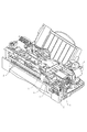
図1は、本発明を適用可能なプリンタの要部の外観図である。図1に示すプリンタは、いわゆるシリアルスキャン型の記録装置であり、記録媒体の搬送方向(副走査方向)に対して直交する方向(主走査方向)における記録ヘッドの走査を伴なって、画像を記録する。記録動作においては、まず、給紙モータ5によりギヤを介して駆動される給紙ローラー6によって、記録媒体が所定位置まで搬送される。それから、キャリッジモータ3によりキャリッジ2を主走査方向に移動させつつ、キャリッジ2に搭載された記録ヘッドからインクを吐出して、記録媒体上に一定のバンド幅の画像を記録する。その後、記録媒体を副走査方向に所定量搬送(以下、「紙送り」ともいう)する。
【0021】
このような動作を繰り返すことにより、記録媒体上に順次画像を記録し、記録媒体上への画像形成を完成する。
【0022】
このようなシリアルスキャン方式においては、記録ヘッドの1走査の記録毎に紙送りはせずに、記録ヘッドの複数走査の記録後に紙送りをする方法もある。
【0023】
また、記録ヘッドの1走査毎に所定のマスクを用いた記録データを間引いて記録し、その1走査毎にバンド幅の1/nの紙送りをして、1バンド幅の画像を記録ヘッドの複数回の走査と複数回の紙送りによって完成させる方法もある。
【0024】
また、本例では、キャリッジモータ3からキャリッジ2への駆動力の伝達手段として、キャリッジベルト4を用いている。しかし、そのキャリッジベルト4の代わりに、リードスクリュー等他の伝達手段を用いてもよい。また、紙送りされた記録媒体は、給紙ローラー6と圧力ローラー7の間を通って、記録ヘッドによる記録位置に導かれる。記録ヘッドは、その休止状態において、パージユニット1のキャップによってキャッピングされており、記録動作に際しては、まず、そのキャップを開放して、キャリッジ2の主走査方向の移動を可能とする。その後、1走査分の記録データがバッファに蓄積されてから、キャリッジモータ3によってキャリッジ2を主走査方向に移動させつつ、記録ヘッドからインクを吐出して画像を記録する。なお、インクは、インクタンクに貯留されるインクを、チューブなどの供給経路を経て記録ヘッドへ供給可能に構成されている。以下、インクタンク、チューブを含むインクの供給経路全般を、インク供給系と称する。
【0025】
図2は、本例の記録装置におけるインク供給系の説明図である。インクは、メインのインクタンク201からチューブ207とジョイント208を経由して、キャリッジ2上のサブのインクタンク202に補給されてから、記録ヘッド9に供給される。
【0026】
インクタンク201において、201Y,201M,201C,201Bは、それぞれイエロー、マゼンタ、シアン、およびブラックのインクの収容部である。記録ヘッド9は、キャリッジ2と共に、シャフト10に沿って主走査方向に移動する。また、図2において、203はバッファ室である。
【0027】
図2に示す構成に限らず、装置本体の定位置に備えたメインタンク201から、直接、記録ヘッド9にインクを供給するように構成してもよい。しかし、キャリッジ2に掛かる負荷を小さく抑えて、高速記録化、小型軽量化を図る上においては、本例のように、キャリッジ2に搭載するサブタンク202を小型化することが有効である。すなわち、キャリッジ2に比較的小容量のサブタンク202を搭載して、そのサブタンク202から記録ヘッド9にインクを供給すると共に、そのサブタンク202に対して、装置本体の定位置に備えた比較的大容量のメインタンク201からインクを補給するように構成することができる。
【0028】
供給ジョイント208は、キャリッジ2がホーム位置などの所定位置に移動したときに、メインタンクとサブタンクとの間のインク供給路を形成する。したがって、サブタンク202の容量や記録ヘッド9のインク消費量に応じた最適な時期に、メインタンク201からサブタンク202にインクを補給することができる。
【0029】
211はインクタンクに取り付けられたインクの残量を記憶するための記憶手段であり、印刷装置本体に取り付けられた際に、印刷装置本体と電気的に接合され、内部のデータの読み出し、書き込みが行われる。この記憶手段は、それぞれの色のインクタンクに搭載される。
【0030】
また、インクタンク201は、PPやPE等の樹脂により、インジェクションやブローあるいは溶着などの成形技術を用いて成形される。タンク201としては、その外装がそのままインクチャンバーとして機能するもの、内部にインクを充填した袋を持つもの、また内部に備えた多孔質体によってインクを保持すると同時に負圧を発生させるもの、等がある。また、負圧発生機構をタンク201に備える場合は、例えば、タンク201内のインク収納用の袋部分を拡大方向に付勢するばね機構等を袋内部または袋外部に設けて、負圧を発生させる構成を採ることができる。本例の場合は、図2に示すようなチューブ207を用いた供給系を備えており、負圧発生源は記録ヘッド9とタンク201との間の水頭差によって生ずるよう構成されている。
【0031】
また、本例のインクタンク201は、PPの外装に対して、底面にあたる部品を溶着することによって構成されている。
【0032】
記録媒体は、インクジェット方式の記録に適するものであれば特に制限はなく、例えば、いわゆる普通紙、紙の上に炭酸カルシウム、TiO2、または結着剤などからなるインク吸収層を設けたコート紙、高分子フィルム上にインクを吸収するAl2O3多孔質体などによる吸収層を設けたフィルム類、などを用いることができる。
【0033】
また、インクに用いられる水溶性有機溶剤としては、従来公知のインクに使用されているものの全てを使用することができる。
【0034】
図3は、本例の記録装置における電気回路の構成を説明する概略図であり、図3において、101はプログラマブル・ペリフェラルインターフェイス(以下、「PPI」という)であり、図示しないホストコンピュータ(ホスト装置)から送られてくる指令信号(コマンド)や記録情報信号を受信してMPU102に転送する。
【0035】
また、PPI101は、表示とキー操作一体型パネル123の制御信号をやりとりし、およびキャリッジ2がホーム位置にあることを検出するホーム位置センサ107からの信号を入力する。また、PPI101は、インクタンクのEEPROM211に対してデータの読み出し、書き込みを行うため、の制御信号とデータをやりとりする。
【0036】
MPU(マイクロプロセッシングユニット)102は、制御用ROM105に記憶された制御プログラムにしたがって、この記録装置内の各部を制御する。103は各種データを一時的に記憶するためのRAMであり、受信した信号を貯え、或いは、MPU102のワークエリアとして使用される。104はフォント発生用ROMであり、コード情報に対応して文字や記録等のパターン情報を記憶しており、入力したコード情報に対応して各種パターン情報を出力する。121は、ROM104等により展開されたデータを記憶するためのプリントバッファメモリであって、m行分の記録データを記憶する容量を持つ。105は、MPU102が実行する処理手順が格納されている制御用ROMである。
【0037】
122はインクタンク側とは別に印刷装置側に設けられたEEPROMである。
【0038】
印刷装置側に設けられたEEPROMには、印刷装置の動作に関わる調整データや、使用履歴などの情報が書き込まれる。
【0039】
これらの各部は、アドレスバス117およびデータバス118を介して、MPU102によりそれぞれ制御される。
【0040】
3はキャリッジモータであり、記録ヘッド9を搭載したキャリッジ2を主走査方向に往復移動させる。また、5は紙送りモータであり、紙等の記録媒体をキャリッジ2の移動方向に対して直交する副走査方向に搬送する。113はキャッピングモータであり、記録ヘッド9をキャッピングするようにキャップ部材を駆動して、記録ヘッド9のインク吐出口(図示せず)を外気より遮断してノズルの乾燥を防止し、またワイパーを動作させて、記録ヘッド9におけるインク吐出口の形成面(ヘッドフェイス面)のインクを拭き取るワイピング等の動作を行う。
【0041】
115はキャリッジモータ3を駆動するためのモータドライバ、116は紙送りモータ5を駆動するためのモータドライバ、114はキャッピングモータ113を駆動するためのモータドライバである。また、表示とキー操作一体型パネル123には、キーボードスイッチや液晶表示器などが設けられている。この操作パネルは、後述するように、記録装置の動作や設定を変更の指示、操作をユーザが行うために設けられるものである。
【0042】
また、ホーム位置センサ107は、キャリッジ2のホーム位置近傍に設けられており、記録ヘッド9を搭載したキャリッジ2がホーム位置に到達したことを検知する。109はシートセンサであり、記録用紙等の記録媒体の有無、すなわち記録媒体が所定の記録部に供給されたか否かを検知する。ホーム位置においては、記録ヘッド9のインク吐出状態を良好に維持するための回復処理を行うことができる。その回復処理としては、ワイパーによるワイピング動作の他に、画像の記録に寄与しないインクを記録ヘッド9からキャップ部材の内部に吐出する処理(予備吐出)、画像の記録に寄与しないインクを吸引力あるいは加圧力によって記録ヘッド9から排出させる処理を含めることができる。
【0043】
本例の記録ヘッド9は、熱エネルギを用いてインクに膜沸騰により気泡の発生を含む状態変化を生起させ、その発泡圧力によってインク滴を吐出する、いわゆるバブルジェット(R)方式のインクジェット記録ヘッドである。
【0044】
この記録ヘッド9には、m個(例えば、64個)の吐出口、および各吐出口に対応したm個の吐出用ヒータ(電気熱変換体)などが設けられている。111は、記録情報信号に応じて記録ヘッド9の吐出用ヒータを駆動するためのドライバである。また、120は、上記各部へ電源を供給する電源部であり、駆動電源装置としてのACアダプタと電池を有している。このような構成において、MPU102は、PPI101を介してコンピュータなどのホスト装置に接続されており、このホスト装置から送られてくるコマンドおよび記録情報信号、制御用ROM105に格納されているプログラムの処理手順、およびRAM106内に蓄えた記録情報に基づいて、記録動作を制御する。
【0045】
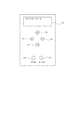
図4は、図1に示したプリンタ外装部分に設けられる表示部パネルとキー操作部分パネルの一例である。パネルは表示部とキー操作部が一体のユニットになっているものでもよい。
【0046】
図4において501は2桁16文字で構成される液晶表示デバイスである。この表示内容は図3のMPU102により制御され印刷状況に応じ、「インサツカノウ」「オフライン」「ペーパージャム」などの表示がなされる。
【0047】
502、505、504、503は上、下、左、右キー、506は実行キーであり、使用者が、紙種などの設定、印字調整に必要な印刷の実行、手動でおこなうヘッドのメンテナンス等のメニューを選択する場合に操作する。また、507はオンラインキーであり、押下するたびにオンライン状態とオフライン状態とを切り替える。
【0048】
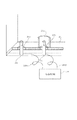
図5はハード構成のインクの検知手段の一例を示す図である。ハード構成のインクの検知手段は、例えば、図5のような供給ピン205と大気連通ピン204を電極として用いて構成することができる。すなわち、供給ピン205と大気連通ピン204は、それぞれ導電性の金属材料によって形成されており、それらには導電線209A,209Bの一端が接続されている。それらの導電線209A,209Bの他端には定電流回路210が接続されている。
【0049】
定電流回路210は、ピン205,204の間に、5Vを最大値として、100μAの直流電流を流すように構成されている。したがって、タンク201内にインクがないとき、あるいはタンク201が装着されていないときには、最大値の電圧5Vが印加され、またタンク201内に存在するインクによってピン205,204が電気的に接続されているときは、インクの抵抗値に応じて印加電圧が変化する。
【0050】
この検知手段は、この印加電圧の変化に基づいて、タンク201内におけるインクの存在を検知する。
【0051】
インクタンク201における各色のインクの収容部201Y,201M,201C,201Bの底面のそれぞれには、図5のように、ゴム201aによるジョイント部分が2ヶ所設けられており、それらのジョイント部分に、装置本体側に設けられたピン204、205が差し込まれる。ピン205は、タンク201内のインクを記録ヘッド9に供給するための供給ピンであり、ピン204は、インクの供給に伴なうタンク201内の負圧上昇によってタンク内に外気圧を導入するための大気連通ピンである。大気連通ピン204が差し込まれるジョイント部分の内側には、そのジョイント部分を囲む所定高さの環状壁部201bが形成されている。
【0052】
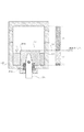
図6は、インクタンク内のインクが所定量以下になったことを検出するための検出原理を説明するための図である。同図中のレベルL1,L2,L3のように、タンク201内のインクの液面はインクの消費量に応じて徐々に下がる。レベルL1のように、大気連通ピン204を囲む環状壁部201bの上端よりもインクの液面が高いときは、その環状壁部201bを越えて存在するタンク201内のインクを介して、電極として機能する大気連通ピン204と供給ピン205との間が電気的に接続される。また、レベルL2のように、環状壁部201bの上端よりもインクの液面が下がったときは、環状壁部201bによって、その内側のインクと外側のインクが遮断され、ピン204,205の間はインクによって接続されない。したがって、レベルL2のように、インクの液面が環状壁部201bの上端に達したとき境(検出ポイントP)として、ピン204,205の間の印加電圧が変化する。
【0053】
ハード構成の検知手段は、その印加電圧の変化に基づいて、インクの液面がレベルL2に達した時点を検知する。
【0054】
タンク201内のインク残量が図6中の範囲A内にあるときは、1ドットあたりの消費量を用いて算出することができる。1ドットあたりの消費量とドットカウンタのカウント値とを乗算し、その乗算値をタンク201の満タン状態におけるインクの充填量から減算することによって、その範囲A内のインク残量を算出することができる。ドットカウントは、画像データなどに基づいて、記録ヘッド9からのインク滴の吐出数をカウントするものであり、タンク201が交換されたときにリセットされる。
【0055】
また、このドットカウンタは、そのカウント値の判定手段と共に、インク残量の検出手段を構成する。その検出手段は、プログラムによってソフト的に構成することができるため、以下、「ソフト構成の検知手段」とも称する。
【0056】
検出ポイントPにおいて、ハード構成の検出手段によって、インクの液面がレベルL2に達したことが検出される。検出ポイントPを過ぎた図6中の範囲Bにおいて、インク残量を継続して算出する。そして、そのインク残量の算出値から、インク残量が範囲C内に入ったことを検知し、インクが空になったと判定する。
【0057】
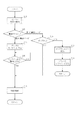
図7は、管理上のインク残量がゼロとなった場合の処理として、動作モードを「第1の動作モード」または「第2の動作モード」に切り替える場合の動作を説明するためのフローチャートである。なお、以下の説明では動作モードについて「切り替える」として説明するが、実際には切り替えの操作によって動作モードが変更されるため、「動作モード変更」とも称してもよい。
【0058】
切り替え動作は、図4に示した操作パネルによりキー入力をすることで行われる。まず第1の動作モードから第2の動作モードに切り替えたいインク色を設定する。プリンタをオフライン状態にし、方向キーでメニューのうちの1つである、第2の動作モード切り替えメニューを選択し、さらにどのインク色に対して、切り替えを行うのかを選択させる(ステップS1)。
【0059】
選ばれたインクタンクに搭載されているEEPROMには、そのインクタンクが第2の動作モードに設定されている(以後、第2の動作モード設定のマーキング)かどうかが書き込まれているので、選ばれたインクタンクに搭載されているEEPROMを読み出し、第2の動作モード設定のマーキングがあるかないかをチェックする(ステップS2)。すでに第2の動作モード設定のマーキングがある場合には、処理を終わる。
【0060】
第2の動作モード設定のマーキングがない場合には、現在第1の動作モードで動作しているということなので、第2の動作モードに設定するための切り替え確認表示を図4の表示部に表示する。この表示としては、例えば「インクザンリョウケンチ オフ?」と表示する(ステップS3)。
【0061】
図4の実行キー以外のキー入力があった場合は、動作モードの切り替え処理を中断したものとして、処理を中断する(ステップS4)。また、図4の実行キーの入力があった場合は、ステップ6に分岐する(ステップS5)。実行キーの入力がない場合は、ステップ4に戻り、いずれかのキー入力があるまで処理を繰り返す。
【0062】
第2の動作モードに設定するための切り替え再確認表示を図4の表示部に表示する。ここでは、例えば「ヨロシイデスカ?」と表示する(ステップS6)。
【0063】
図4の実行キー以外のキー入力があった場合は、動作モードの切り替え処理を中断したものとして、処理を中断する(ステップS7)。図4の実行キーの入力があった場合は、ステップ9に分岐する(ステップS8)。実行キーの入力がない場合は、ステップ7に戻り、いずれかのキー入力があるまで処理を繰り返す。
【0064】
ステップS9では、選ばれたインクタンクに搭載されているEEPROMに、第2の動作モード設定のマーキングを書き込む。プリンタ本体側に搭載されているEEPROMに、第2の動作モード設定インクを使用したことの履歴情報を書き込む(ステップS10)。
【0065】
このような履歴情報の書き込みは、図3に示す制御手段であるMPUの制御によって行われるものであるが、他の書き込み制御用のデバイスを備えた構成としてもよい。
【0066】
この履歴情報により、管理上のインク残量がゼロとなったときに、ユーザの処理により、記録動作を継続して実行可能な第2動作モードに切り替えた経緯があることをプリンタ本体でも管理することができる。また、プリンタ本体では、管理上のインク残量がゼロとなった後に第2動作モードに切り替えた履歴を、装着されているインクタンクについてのみならず、長期にわたって交換されたインクタンクそれぞれについて管理でき、インクタンクの交換作業が行われた履歴や、第2動作モードに切り替えられた回数などについても履歴情報として管理することが可能となっている。
【0067】
なお、この履歴情報は、メーカー、及び、サービスマンなどが参照可能な情報として管理されるものであり、このように構成することで、プリンタ装置本体のメンテナンスを行うサービスマンや、故障発生時の修理を行う修理作業者が、プリンタの使用履歴を知ることができ、メンテナンスや修理の作業においてその情報を活用することができる。
【0068】
この実施例では、動作モードの切り替えは、第1の動作モードから第2の動作モードへの切り替えのみを許可している。
【0069】
これは、ひとたび第1の動作モードから第2の動作モードに設定してしまうと、以後インク残量管理が正しく行われなくなるので、ユーザの操作では、第2の動作モードから第1の動作モードには戻せないという考え方によるものであるが、本発明において第1の動作モードと第2の動作モードを自在に設定させるようにすることも無論可能である。
【0070】
この実施例では、動作モードをインクタンク側のEEPROMに書き込んでいるが、本体側のEEPROMに記憶していてもかまわない。
【0071】
図8は、記録動作開始時の処理を説明するためのフローチャートである。
【0072】
この図8のフローにおいて、まず、記録動作を開始する前に、インク残量の検知(ステップS11)を行い、インクタンクのEEPROMを読み取って第2の動作モードの設定マーキングの有無を確認することにより、動作モードが「第1の動作モード」に設定されているのか、「第2の動作モード」に設定されているのかを判別する(ステップS12)。このステップ1で「第1の動作モード」に設定されている場合はステップS16に分岐し、「第2の動作モード」に設定されている場合はステップS13に分岐する。
【0073】
まず動作モードが第1の動作モードに設定されていた場合について説明する。この場合はインクの残量の管理が正常に行われているケースである。インクがあるかないかを判断し(ステップS16)、インクがない場合は、ステップS17に分岐し、インクなしとして印刷処理を中断し、エラーを発する。この場合は、印字は実行されず、プリンタをオフラインにし(ステップS18)処理を終わる。
【0074】
ステップS16においてインクがあると判断された場合は、ステップS15に分岐し、通常に印刷を実行し処理を終わる。インクがないときに印刷をさせないようにして、印字ヘッドを保護するのが、第1の動作モードで行うインク残量管理の目的であり、フローチャートの説明からこの目的にあった動作が実現されていることが判る。
【0075】
次に、動作モードが第2の動作モードに設定されている場合について説明する。この第2の動作モードは、管理上のインク残量がゼロとなった場合に、ユーザ自身の操作によって記録動作を継続して実行可能な状態とした動作モードである。例えば、管理上のインク残量がゼロとなってもインクタンクに実際にわずかに残るインクを使って記録動作を継続するものであり、従ってこの動作モードではインク残量の管理を行わずに記録動作を実行するよう制御される。
【0076】
ステップS12で動作モードが第2の動作モードであると判定された場合、まずプリンタをオフラインとし(ステップS13)、その後、プリンタに設けられているオンラインボタンが使用者によって、押下られるまで、印刷動作を保留する(ステップS14)。使用者によってオンラインボタンが押下げられることによって、ステップS15に分岐し、通常に印刷を実行し処理を終わる。つまり、第2の動作モードにおいては、記録動作の実行の指示があったとき、記録装置に設けられる操作手段を介して所定の操作が行われたか否かを確認し、ユーザによる所定の操作(ここではオンライン状態に切り替える操作)が行われてから、記録動作を行うよう制御される。
【0077】
このように、記録動作の開始時に、ユーザに対してオンラインボタンを押す行為を要求することで、装置によるインク残量の管理が無効となっている動作モードにあることを知らせることができる。また、このユーザの操作は、プリンタ本体に対して行うものであり、オンラインボタンの操作によって記録動作が開始されるため、ユーザは記録された結果を確認する機会が増えることとなる。このことは、記録動作の開始の指示がプリンタ本体とは別のホスト装置で行われることが一般的であり、第2の動作モードにおいてはプリンタ本体の操作をも必要とすることで、ユーザがプリンタ本体やプリントされた結果を注視することを促すことを可能するものである。従って、インク残量の管理が行われていなくても、実際のインク残量がゼロとなって記録動作が正常に行われていない状態をユーザが比較的早く気づくこととなる。従って、インクが無くなった状態において記録動作を継続して行った場合の記録ヘッドへの影響を小さくし、記録ヘッドの損傷を抑えることが可能となる。
【0078】
また、本実施形態で説明したように、第2の動作モードへ切り替えられたことを本体の記憶手段であるEEPROMに履歴情報として記憶させることで、例えば、ユーザ自身の処置によって管理上のインク残量がゼロとなっても記録動作を継続して行えるよう、インクの供給系を改造した場合においても、履歴情報を確認によって第2動作モードに切り替えられたことをサービスマンが知ることができ、装置本体や記録ヘッドに障害が発生したことの要因をサービスマンが知る、もしくは推測することが可能となる。
【0079】
このように、本実施形態例では、管理上のインク残量がゼロとなった後に継続して記録動作を可能とした第2の動作モードであることの報知を、記録動作時にオンラインボタンの押下行為をユーザへ要求することで実現している。
【0080】
なお、オンラインとする指示は、前述した図4の操作用のパネル123を介して行われるものであるが、このユーザが操作するためのプリンタの機構は図4の例に限らず、単にオンラインボタンのみをプリンタ本体に設けた構成としてもよい。
【0081】
また、第2の動作モードにおいて、記録動作の指示があったときにユーザのボタン操作が行われてから記録動作を行うようにする制御は、図3に示す制御手段であるMPU102によって実行されるものである。なお、本実施形態においては、上述したように、第2の動作モードにおいて記録動作の指示があった場合、ユーザによりオンラインとする操作を待ってから記録動作を行う例を挙げて説明したが、他の操作、例えば、記録開始指示用のボタンや、記録再開指示するボタンの操作によって記録動作を行うよう構成してもよい。
【0082】
(第2の実施形態)
次に、本発明の第2の実施形態を、図を参照して説明する。
【0083】
インクジェットプリンタの基本的構成、および、インク残量や、図7に示す処理については上述した第1の実施形態と同様であり、その説明は省略する。
【0084】
本実施形態は、第1の実施形態における図8の処理に代えて、図9に示す処理とするものであり、以下、その説明を行う。
【0085】
図9は、記録動作開始時の処理を説明するためのフローチャートである。このフローチャートで示す各ステップについて、図8のフローチャートと同じ工程については、図8と同じステップで示している。
【0086】
この図9に示すフローチャートは、管理上のインク残量を大きく超えてプリンタを使用した場合、特に、プリンタ本体の想定される使用状態を逸脱して動作している状態を検知して、ユーザに報知し得るものである。
【0087】
まず、記録動作を開始する前に、インク残量の検知(ステップS11)を行った後、インクタンクのEEPROMを読み取って第2の動作モードの設定マーキングの有無を確認することにより、動作モードが「第1の動作モード」に設定されているのか、「第2の動作モード」に設定されているのかを判別する(ステップS12)。ここで、「第1の動作モード」に設定されている場合はステップS21に分岐し、「第2の動作モード」に設定されている場合はステップS13に分岐する。
【0088】
まず動作モードが第1の動作モードに設定されていた場合について説明する。この場合はインクの残量の管理が正常に行われているケースである。まず、ステップS21でインクの液面が図6のレベルL2より下がっているかどうかを判別する。ステップS21のインク残量の検知においては、図6で示したように機械的な構成の電極を備えたインク検知手段を用いて、インク残量を検知するものである。ステップS21により、図6で示したレベルL2より下がっていると判断された場合には、処理はステップS16に分岐する。また、図6で示したレベルL2より上にある場合は、ステップS22に分岐する。インクの残量がレベルL2以下の場合には、インクの有無(図6で示される範囲Cにはいったか)を、その後のドットカウント値から判断し(ステップ6)、インクがない場合はステップ7に分岐し、インクなしとして印刷処理を中断し、エラーを発する(ステップS17)。この場合は、印字は実行されず、プリンタをオフラインにし(ステップS18)処理を終わる。
【0089】
ステップS16においてインクがあると判断された場合には、ステップS15に分岐し、通常に印刷を実行し処理を終わる。
【0090】
ステップS21の判断において、インクの液面が図6のレベルL2より上がっている場合には、ステップS22に分岐する。このステップS22ではドットカウント方式によりそれまでに使用したインクの消費量をてらして、そもそも充填されているインクの量を超えてしまったかどうかを判断する。
【0091】
ドットカウント方式にはそもそもある程度の誤差が存在するが。それでもなお充填量の1.2倍をこえても、液面が図6のレベル2より上にある場合には、プリンタの装置本体が想定しない使用状態にあるものと判断することができる。
【0092】
このように、充填量の1.2倍をこえている場合はステップS17に処理を移行し、印刷処理を中断し、エラーを発する(ステップS17)。この場合は、印字は実行されず、プリンタをオフラインにし(ステップS18)処理を終わる。
【0093】
ドットカウント方式によるインクの消費量が、そもそもの充填量の1.2倍をこえていない場合には、プリンタの装置本体が通常想定する使用状況にある、もしくはプリンタが正常に動作していると判断し、処理をステップ5に移行し、通常通りに印刷を実行し処理を終わる。
【0094】
ドットカウント方式によるインク使用量やインク残量の推定にはある程度の誤差があるが、インクの供給系の不具合や記録ヘッドの吐出異常によってインクが正常な状態よりも少ない量で吐出されることがあった場合には、ドットカウントで推定したインク残量と、実際のインク残量との差が大きくなってしまう。このような場合には、記録される画像にも影響が生じるため、本実施形態においてはその異常な状態が発生しているものと推測して、印刷動作を未然に停止し、ユーザへ異常状態を報知することが可能である。
【0095】
また、前述のように、ユーザ自身によるインク供給系への処置によって、プリンタが想定していない使用状況にある場合においても、第1の動作モードによるドットカウント値がインクタンクのインク充填量を大きく超えた値に達する場合がある。メーカで想定していない使用状況においては、プリンタ本体や記録ヘッドが損傷する可能性も高くなる。従って、本実施形態によれば、そのようなメーカが保証可能な範囲を超えた処置がユーザ自身により行われた場合においても、プリンタ本体や記録ヘッドの損傷を招く可能性を小さくすることができる。
【0096】
なお、ステップS2において動作モードが第2の動作モードに設定されていると判定された場合の処理は、図8のフローチャートと同様であり、その説明は省略する。
【0097】
この第2の動作モードにおける処理によれば、第1の実施形態と同様に、ユーザがプリンタ本体やプリントされた結果を注視することを促すことを可能とすることができる。従って、インク残量の管理が行われていなくても、実際のインク残量がゼロとなって記録動作が正常に行われていない状態をユーザが比較的早く気づくこととなる。その結果、インクが無くなった状態において記録動作を継続して行った場合の記録ヘッドへの影響を小さくし、記録ヘッドの損傷を抑えることが可能となる。
【0098】
なお、上述の第1の実施形態、および第2の実施形態においては、図8,9に示すフローチャートにより、第2の動作モードにおいて、記録開始時にプリンタをオフラインとし、ユーザの操作によってオンライン状態とすることで、ユーザ自身にプリンタ本体を確認させる機会を設けたものであるが、以降の記録動作において、例えば、連続して数頁から数十頁分の記録動作を行う場合には、毎頁、もしくは数頁の記録動作毎にオフライン動作に切り替える処理とするよう構成してもよい。特に、管理上のインク残量がゼロとなった状態においては、どの時点で実際のインク残量がゼロとなるかはプリンタ本体で管理することが困難であるため、比較的高い頻度でユーザ自身にプリンタ本体を操作させる機会を設けることで、その度にユーザにプリンタ本体やプリントの結果を確認させることができる。従って、実際のインク残量がゼロとなって記録が行えない状態となった場合においても、比較的早くユーザが知ることができ、記録紙の無駄な消費を防ぐことができるだけでなく、記録ヘッドやプリンタ本体の損傷を小さく抑えることが可能となる。
【0099】
また、上述したようなユーザ自身によるインク供給系の改造としては、本体の使用可能な組成以外のインクや他の液体を補充する場合が考えられる。ユーザの責任下において処置された改造であっても、プリンタ本体や記録ヘッドの損傷を可能な限り小さく抑えることが好ましく、このような改造がなされた場合において仮に異常が発生したとしても、ユーザ自身にプリンタ本体を操作させる機会を設けるよう構成することで、ユーザ自身はその異常を比較的早く知ることができ、その結果、プリンタ本体や記録ヘッドの寿命を延ばすことができ、結果としてプリンタのランニングコストを低減することができる。
【0100】
【発明の効果】
以上説明したように、本発明によれば、管理上のインク残量がゼロとなった場合に、通常の記録動作を行う第1のモードから、インク残量の管理を行わずに記録動作を行う第2の動作モードに切り替え可能とし、第2の動作モードにおいては、記録動作を実行する際に、ユーザのプリンタ本体の操作を介して記録動作を実行可能とすることで、インク残量の管理を行わない状態において、実際のインク残量がゼロとなった場合に生じる不具合や異常を早期にユーザが知ることができる。その結果、プリンタ本体や記録ヘッドに生じ得る損傷を抑えることができ、プリンタ本体や記録ヘッドの高寿命化を達成することができる。
【図面の簡単な説明】
【図1】本発明を適用可能な記録装置の斜視図である。
【図2】図1の記録装置におけるインクの供給系の構成図である。
【図3】図1の記録装置における制御系のブロック構成図である。
【図4】図1に示したプリンタ外装部分に設けられる表示部パネルとキー操作部分パネルの一例を示す概略図である。
【図5】図1の記録装置におけるインクタンクの底部付近の拡大断面図である。
【図6】インク残量の警告表示方法を説明する図。
【図7】動作モードの切替え処理を説明するためのフローチャートである。
【図8】記録動作開始時の処理を説明するためのフローチャートである。
【図9】記録動作開始時の処理を説明するためのフローチャートである。
【符号の説明】
1 パージユニット
2 キャリッジ
3 キャリッジモータ
4 キャリッジベルト
5 搬送モータ
6 給紙ローラ
7 圧力ローラ
201 メインタンク
202 サブタンク[0001]
TECHNICAL FIELD OF THE INVENTION
The present invention relates to an ink jet recording apparatus that records an image on a recording medium by discharging ink. In particular, the present invention relates to a system for detecting the remaining amount of ink in an ink tank detachably mounted on an ink jet recording apparatus or managing the remaining amount of ink.
[0002]
[Prior art]
In a recording apparatus (hereinafter, also referred to as a printing apparatus) using an ink-jet technology, a heating element (heater) is used as a recording element, and ink is vaporized by thermal energy generated by the heating element, and bubbles generated in the ink at that time 2. Description of the Related Art A bubble jet (R) type ink jet recording apparatus that discharges ink with the expansion force of a liquid is known.
[0003]
In the ink jet type recording apparatus, when the recording operation is performed by discharging the ink in a state where the ink is exhausted, the recording head cannot expect the cooling effect by the heat of vaporization, and the recording is performed without the ink. If the driving of the head is continued, the heating element of the recording head may be damaged, and it may not be possible to generate sufficient thermal energy for ejection, or a problem may occur that the heating element is disconnected.
[0004]
In order to avoid such a problem, a method of managing an ink remaining amount by providing an electrically erasable and writable electric element (hereinafter referred to as an EEPROM) in an ink tank has been put to practical use.
[0005]
The management of the ink remaining amount is to manage the amount of used ink or the amount of ink remaining in the ink tank by always writing the remaining amount of ink or the amount of consumption into the EEPROM in accordance with the consumption of ink. It is. Specifically, this method predicts the amount of ink ejected by image data, counts the number of dots ejected by image data, or directly counts the number of times the ejection heating element is driven. There are methods.
[0006]
By such management of the remaining amount of ink, for example, when the value indicating the remaining amount of ink becomes zero, the printing operation is prohibited, thereby preventing the print head from being damaged by heat generation. it can.
[0007]
Further, Japanese Patent Application Laid-Open No. H11-133, which discloses an invention relating to management of the remaining amount of a recording agent, prohibits image formation when toner runs out, and then reliably determines whether or not toner has been replenished. A configuration is described in which prohibition of formation can be correctly released. Patent Document 2 discloses a configuration in which the number of printable sheets is managed using the remaining amount of ink, and image recording is stopped until an ink tank that has run out of ink is replaced with a new ink tank. Has been described.
[0008]
[Patent Document 1]
JP 05-181364 A
[Patent Document 2]
JP-A-07-025030
[0009]
[Problems to be solved by the invention]
By performing the above-described ink remaining amount management, if the printing operation is stopped when the ink runs out, it is possible to prevent the recording head from being damaged.
[0010]
However, there may be slight variations in the amount of ink actually ejected or variations in the amount of ink ejected due to environmental conditions. In order to prevent the remaining amount of ink from becoming zero, it is conceivable to manage so that the remaining amount of ink in management becomes zero slightly earlier. In other words, it is inappropriate for the user to be unable to perform printing before the ink remaining amount in management becomes zero, which is inappropriate in consideration of user's convenience. The ink remaining amount is managed to be smaller than the actual ink remaining amount, and before the ink is actually run out, the ink remaining amount becomes zero in management, so that the user is encouraged to replace the ink tank, and recording is performed. It is general that the head is configured to prevent damage.
[0011]
In the case of such a configuration, the actual remaining amount of ink when the remaining amount of ink becomes zero varies from the viewpoint of management. It is also assumed that Further, even if the ink remaining amount in management becomes zero during the recording operation, it is necessary to prevent the recording paper from being wasted during the recording by continuing the recording operation. For this reason, it is a design requirement that the printing operation be continued even when the ink remaining amount on the management becomes zero, or that the printing operation can be executed in accordance with the printing operation instruction by the user. It is.
[0012]
As described above, by enabling the recording operation even when the ink remaining amount becomes zero, the running cost can be reduced and the user's convenience is improved. The remaining ink amount becomes zero, which causes a problem.
[0013]
In addition, it is assumed that the ink supply system is modified under the user's own responsibility so that the recording operation can be continuously performed even after the ink remaining amount in management becomes zero. In this case, there is a possibility that ink may leak from the ink supply system or a failure may occur due to an influence on a mechanism inside the printing apparatus. It is difficult for the manufacturer to guarantee all failures caused by such a user's own action that is not expected by the device manufacturer. Even when such a measure is taken by the user to enable the operation even if the ink remaining amount on the management becomes zero, the failure of the apparatus itself and the damage of the recording head can be minimized. Although preferred, it could not be addressed with the conventional arrangement.
[0014]
The present invention focuses on such a problem that arises in the management of the remaining amount of ink, and when the printing operation is continuously performed after the remaining amount of ink in the management becomes zero, the actual operation is performed. By making it possible for the user to know at a relatively early stage that the recording has become impossible due to the remaining amount of ink being zero, it is possible to minimize damage to the recording head. Aim.
[0015]
[Means for Solving the Problems]
In order to achieve the above object, the present invention provides an ink jet recording apparatus that performs recording by ejecting ink supplied from an ink tank that is exchangeably mounted to a recording medium from a recording head. Operating means for changing settings and settings, a remaining amount managing means for managing the remaining amount of ink in the attached ink tank, and an ink remaining amount in the ink tank managed by the remaining amount managing means as the ink is consumed. If it is determined that the remaining amount has run out, the first operation mode in which the subsequent recording operation by the recording head is inhibited and the first operation mode are performed regardless of the remaining amount of ink managed by the remaining amount management unit. A mode change unit capable of changing to a second operation mode in which the operation can be continuously executed, and, when an instruction to execute a recording operation is given in the second operation mode, Control means for operating the user controls to perform the recording operation from being performed through the operating means, characterized by having a.
[0016]
Further, in the present invention, the operating means has an online switching means for switching a connection state with a host device connected to the outside of the recording apparatus between an online state and an offline state, and the control means comprises In the operation mode, when the recording operation is instructed, the connection state with the host device is set to the offline state, and subsequently, after the user switches to the online state by operating the online switching unit, the recording operation is performed. It is characterized in that it is controlled to perform.
[0017]
The recording apparatus may further include a remaining amount detecting unit configured to detect that a remaining amount of the ink in the ink tank is equal to or less than a predetermined amount, wherein the control unit is configured to control the remaining amount of the ink in the first operation mode. When the amount of ink consumed in the attached ink tank exceeds the predetermined amount in a state in which the remaining amount of ink is not detected to be equal to or less than the predetermined amount by the amount detecting means, control is performed so that the recording operation is not performed. Features.
[0018]
The present invention also relates to a method for controlling an ink jet recording apparatus which performs recording by discharging ink supplied from an ink tank which is mounted in a replaceable manner from a recording head to a recording medium. In a state in which the amount is reduced, a first operation mode in which the recording operation is prohibited and a second operation mode in which the recording operation can be executed can be switched. In the second operation mode, the recording operation is stopped. When an execution instruction is given, it is checked whether or not a predetermined operation has been performed via an operation unit provided in the recording apparatus, and after the predetermined operation has been performed by the user, control is performed so as to perform a recording operation. It is characterized by the following.
[0019]
BEST MODE FOR CARRYING OUT THE INVENTION
Hereinafter, embodiments of the present invention will be described in detail with reference to the drawings.
[0020]
(1st Embodiment)
FIG. 1 is an external view of a main part of a printer to which the present invention can be applied. The printer shown in FIG. 1 is a so-called serial scan type recording apparatus, which prints an image by scanning a recording head in a direction (main scanning direction) orthogonal to a conveying direction of a recording medium (sub scanning direction). Record. In the recording operation, first, a recording medium is transported to a predetermined position by a
[0021]
By repeating such an operation, images are sequentially recorded on the recording medium, and the image formation on the recording medium is completed.
[0022]
In such a serial scan method, there is also a method in which the paper is not fed each time one print of the print head is printed, but is fed after the print head has printed a plurality of scans.
[0023]
Further, the print data using a predetermined mask is thinned out and printed at each scan of the print head, and a paper feed of 1 / n of the bandwidth is performed at each scan to print an image of one bandwidth. There is also a method of completing by performing a plurality of scans and a plurality of paper feeds.
[0024]
In this embodiment, the
[0025]
FIG. 2 is an explanatory diagram of an ink supply system in the printing apparatus of the present embodiment. The ink is supplied from the
[0026]
In the
[0027]
The configuration is not limited to the configuration illustrated in FIG. 2, and the ink may be directly supplied to the
[0028]
The supply joint 208 forms an ink supply path between the main tank and the sub tank when the carriage 2 moves to a predetermined position such as a home position. Therefore, ink can be supplied from the
[0029]
[0030]
The
[0031]
In addition, the
[0032]
The recording medium is not particularly limited as long as it is suitable for inkjet recording. For example, so-called plain paper, coated paper provided with an ink absorbing layer made of calcium carbonate, TiO2, or a binder on paper, Films provided with an absorption layer of a porous film of Al2O3 that absorbs ink on a polymer film, or the like can be used.
[0033]
As the water-soluble organic solvent used in the ink, all of those conventionally used in known inks can be used.
[0034]
FIG. 3 is a schematic diagram illustrating a configuration of an electric circuit in the recording apparatus of the present embodiment. In FIG. 3, reference numeral 101 denotes a programmable peripheral interface (hereinafter, referred to as “PPI”), which is not shown in the drawing. ) Is received and transferred to the
[0035]
Further, the PPI 101 exchanges a display and a control signal of the key operation integrated
[0036]
An MPU (microprocessing unit) 102 controls each unit in the recording apparatus according to a control program stored in a
[0037]
[0038]
Adjustment data relating to the operation of the printing apparatus and information such as usage history are written in an EEPROM provided on the printing apparatus side.
[0039]
These components are controlled by the
[0040]
A
[0041]
A
[0042]
The
[0043]
The
[0044]
The
[0045]
FIG. 4 is an example of a display panel and a key operation panel provided on the exterior part of the printer shown in FIG. The panel may be a unit in which the display unit and the key operation unit are integrated.
[0046]
In FIG. 4, reference numeral 501 denotes a liquid crystal display device including two digits and 16 characters. The display contents are controlled by the
[0047]
[0048]
FIG. 5 is a diagram showing an example of a hardware ink detecting unit. The ink detecting means having a hardware configuration can be configured using, for example, a
[0049]
The constant
[0050]
This detecting means detects the presence of ink in the
[0051]
As shown in FIG. 5, two joint portions made of
[0052]
FIG. 6 is a diagram for explaining a detection principle for detecting that the amount of ink in the ink tank has become equal to or less than a predetermined amount. As shown at levels L1, L2, and L3 in the figure, the ink level in the
[0053]
The detection means having a hardware configuration detects a point in time when the liquid level of the ink reaches the level L2 based on the change in the applied voltage.
[0054]
When the remaining amount of ink in the
[0055]
The dot counter, together with the count value determination means, constitutes a remaining ink amount detection means. Since the detection means can be configured in a software manner by a program, it is hereinafter also referred to as “soft configuration detection means”.
[0056]
At the detection point P, the detection unit having the hardware configuration detects that the ink level has reached the level L2. In the range B in FIG. 6 past the detection point P, the remaining ink amount is continuously calculated. Then, based on the calculated value of the remaining ink amount, it is detected that the remaining ink amount has entered the range C, and it is determined that the ink has become empty.
[0057]
FIG. 7 is a flowchart for explaining an operation in a case where the operation mode is switched to the “first operation mode” or the “second operation mode” as the process when the remaining ink amount in management becomes zero. is there. In the following description, the operation mode is described as “switching”. However, since the operation mode is actually changed by the switching operation, it may be referred to as “operation mode change”.
[0058]
The switching operation is performed by key input using the operation panel shown in FIG. First, an ink color desired to be switched from the first operation mode to the second operation mode is set. The printer is set to the off-line state, and the direction key is used to select one of the menus, the second operation mode switching menu, and to select which ink color is to be switched (step S1).
[0059]
In the EEPROM mounted on the selected ink tank, it is written whether or not the ink tank is set to the second operation mode (hereinafter, marking of the second operation mode setting). The EEPROM mounted on the selected ink tank is read, and it is checked whether or not there is a marking for the second operation mode setting (step S2). If there is already a marking for the second operation mode setting, the process ends.
[0060]
If there is no marking for the second operation mode setting, it means that the camera is currently operating in the first operation mode, and a switching confirmation display for setting the second operation mode is displayed on the display unit in FIG. I do. As this display, for example, “Ink off is off?” Is displayed (step S3).
[0061]
If there is a key input other than the execution key in FIG. 4, the process is interrupted assuming that the operation mode switching process has been interrupted (step S4). If the execution key shown in FIG. 4 has been input, the process branches to step 6 (step S5). If there is no input of the execution key, the process returns to step 4 and the process is repeated until there is any key input.
[0062]
A switching reconfirmation display for setting the second operation mode is displayed on the display unit in FIG. In this case, for example, “Yoshishidesuka?” Is displayed (step S6).
[0063]
When there is a key input other than the execution key in FIG. 4, it is assumed that the operation mode switching process has been interrupted, and the process is interrupted (step S7). If the execution key shown in FIG. 4 has been input, the process branches to step 9 (step S8). If there is no input of the execution key, the process returns to step 7, and the process is repeated until there is any key input.
[0064]
In step S9, the marking of the second operation mode setting is written in the EEPROM mounted on the selected ink tank. The history information indicating that the second operation mode setting ink has been used is written into an EEPROM mounted on the printer body (step S10).
[0065]
Writing of such history information is performed under the control of the MPU, which is the control means shown in FIG. 3, but may be configured to include another write control device.
[0066]
According to the history information, when the ink remaining amount in management becomes zero, it is also managed by the printer main body that there is a history of switching to the second operation mode in which the printing operation can be continuously performed by the user's process. be able to. Further, the printer main body can manage the history of switching to the second operation mode after the ink remaining amount in management becomes zero not only for the installed ink tank but also for each ink tank that has been replaced for a long time. It is also possible to manage the history of the ink tank replacement work, the number of times of switching to the second operation mode, and the like as history information.
[0067]
Note that this history information is managed as information that can be referred to by a manufacturer, a service person, and the like. With such a configuration, a service person who performs maintenance of the printer device main body, and information on occurrence of a failure. A repair worker who performs repairs can know the usage history of the printer, and can use the information in maintenance and repair work.
[0068]
In this embodiment, the switching of the operation mode permits only the switching from the first operation mode to the second operation mode.
[0069]
This is because once the operation mode is set from the first operation mode to the second operation mode, the remaining ink amount cannot be properly managed thereafter. However, it is of course possible to freely set the first operation mode and the second operation mode in the present invention.
[0070]
In this embodiment, the operation mode is written in the EEPROM of the ink tank. However, the operation mode may be stored in the EEPROM of the main body.
[0071]
FIG. 8 is a flowchart for explaining the processing at the start of the recording operation.
[0072]
In the flow of FIG. 8, first, before starting the recording operation, the remaining amount of ink is detected (step S11), and the EEPROM of the ink tank is read to confirm the presence or absence of the marking for setting the second operation mode. Thus, it is determined whether the operation mode is set to the “first operation mode” or the “second operation mode” (step S12). If the "first operation mode" is set in step 1, the process branches to step S16, and if the "second operation mode" is set, the process branches to step S13.
[0073]
First, a case where the operation mode is set to the first operation mode will be described. In this case, the management of the remaining amount of ink is performed normally. It is determined whether or not there is ink (step S16). If there is no ink, the flow branches to step S17, where the printing process is interrupted with no ink and an error is issued. In this case, printing is not performed, and the printer is taken off-line (step S18), and the process ends.
[0074]
If it is determined in step S16 that there is ink, the flow branches to step S15, where printing is normally performed, and the process ends. Protecting the print head by preventing printing when there is no ink is the purpose of the remaining ink amount management performed in the first operation mode, and the operation corresponding to this purpose is realized from the description of the flowchart. It turns out that there is.
[0075]
Next, a case where the operation mode is set to the second operation mode will be described. The second operation mode is an operation mode in which, when the remaining amount of ink in management becomes zero, the printing operation can be continuously executed by a user's own operation. For example, even if the ink remaining amount in management becomes zero, the printing operation is continued using the ink that actually remains in the ink tank, and therefore, in this operation mode, printing is performed without managing the ink remaining amount. The operation is controlled to be performed.
[0076]
If it is determined in step S12 that the operation mode is the second operation mode, the printer is first taken offline (step S13), and then the printing operation is performed until the user presses the online button provided on the printer by the user. Is suspended (step S14). When the online button is pressed by the user, the process branches to step S15, where printing is normally performed and the process ends. That is, in the second operation mode, when an instruction to execute a recording operation is issued, it is determined whether or not a predetermined operation has been performed via an operation unit provided in the recording apparatus, and a predetermined operation ( Here, an operation of switching to an online state) is performed, and then the recording operation is controlled to be performed.
[0077]
In this way, by requesting the user to press the online button at the start of the recording operation, it is possible to notify that the apparatus is in an operation mode in which the management of the remaining ink amount by the apparatus is invalid. Further, this user operation is performed on the printer main body, and the recording operation is started by operating the online button, so that the user has more opportunities to confirm the recorded result. This is because the instruction to start the recording operation is generally issued by a host device different from the printer main body, and in the second operation mode, the user also needs to operate the printer main body. It is possible to prompt the user to pay close attention to the printer body and the printed result. Therefore, even if the management of the remaining ink amount is not performed, the user will relatively quickly recognize that the actual remaining ink amount is zero and the recording operation is not normally performed. Accordingly, it is possible to reduce the influence on the print head when the print operation is continuously performed in a state where the ink is exhausted, and to suppress the damage of the print head.
[0078]
Further, as described in the present embodiment, the fact that the operation mode has been switched to the second operation mode is stored as history information in an EEPROM serving as a storage unit of the main body. Even when the ink supply system is modified so that the recording operation can be continued even when the amount becomes zero, the serviceman can know that the mode has been switched to the second operation mode by checking the history information, The serviceman can know or presume the cause of the failure of the apparatus main body and the recording head.
[0079]
As described above, in the present embodiment, the notification of the second operation mode in which the printing operation can be continuously performed after the management ink remaining amount becomes zero is notified by pressing the online button during the printing operation. It is realized by requesting a user to perform an action.
[0080]
The online instruction is given through the
[0081]
Further, in the second operation mode, the control for performing the recording operation after the button operation of the user is performed when the recording operation is instructed is executed by the
[0082]
(Second embodiment)
Next, a second embodiment of the present invention will be described with reference to the drawings.
[0083]
The basic configuration of the ink jet printer, the remaining amount of ink, and the processing shown in FIG. 7 are the same as in the first embodiment described above, and a description thereof will be omitted.
[0084]
In the present embodiment, the process shown in FIG. 9 is used instead of the process shown in FIG. 8 in the first embodiment, and a description thereof will be given below.
[0085]
FIG. 9 is a flowchart for explaining the processing at the start of the recording operation. Regarding the steps shown in this flowchart, the same steps as those in the flowchart of FIG. 8 are shown in the same steps as FIG.
[0086]
The flowchart shown in FIG. 9 is used when the printer is used in a state where the amount of ink used in the printer greatly exceeds the management remaining amount. It can be informed.
[0087]
First, before the printing operation is started, the remaining ink amount is detected (step S11), and then the EEPROM of the ink tank is read to confirm the presence / absence of the setting mark of the second operation mode. It is determined whether the mode is set to the "first operation mode" or the "second operation mode" (step S12). Here, when the “first operation mode” is set, the process branches to step S21. When the “second operation mode” is set, the process branches to step S13.
[0088]
First, a case where the operation mode is set to the first operation mode will be described. In this case, the management of the remaining amount of ink is performed normally. First, in step S21, it is determined whether or not the ink level is lower than the level L2 in FIG. In the detection of the remaining amount of ink in step S21, the remaining amount of ink is detected by using an ink detecting unit having a mechanically configured electrode as shown in FIG. If it is determined in step S21 that the level is lower than the level L2 shown in FIG. 6, the process branches to step S16. If it is above the level L2 shown in FIG. 6, the process branches to step S22. If the remaining amount of ink is equal to or lower than the level L2, the presence / absence of ink (whether the ink has entered the range C shown in FIG. 6) is determined from the subsequent dot count value (step 6). The printing process is interrupted with no ink, and an error is issued (step S17). In this case, printing is not performed, and the printer is taken off-line (step S18), and the process ends.
[0089]
If it is determined in step S16 that there is ink, the flow branches to step S15, where printing is normally performed, and the process ends.
[0090]
If it is determined in step S21 that the ink level is higher than the level L2 in FIG. 6, the process branches to step S22. In this step S22, the consumed amount of the ink used so far is determined by the dot count method, and it is determined whether or not the amount of the ink that has been filled has exceeded the amount of the ink that has been filled in the first place.
[0091]
Although there are some errors in the dot counting system in the first place. If the liquid level is still higher than the level 2 in FIG. 6 even if the filling amount exceeds 1.2 times, it can be determined that the printer main body is in an unexpected use state.
[0092]
As described above, when the filling amount exceeds 1.2 times, the process shifts to step S17, the printing process is interrupted, and an error is issued (step S17). In this case, printing is not performed, and the printer is taken off-line (step S18), and the process ends.
[0093]
If the amount of ink consumed by the dot count method does not exceed 1.2 times the original filling amount, it is assumed that the printer device is in a normally used condition or that the printer is operating normally. Judgment is made, the process proceeds to step 5, printing is executed as usual, and the process ends.
[0094]
There is some error in estimating the amount of ink used and the remaining amount of ink by the dot count method.However, ink may be ejected in a smaller amount than normal due to malfunction of the ink supply system or abnormal ejection of the recording head. If there is, the difference between the ink remaining amount estimated by the dot count and the actual ink remaining amount becomes large. In such a case, the recorded image is also affected. In the present embodiment, it is assumed that the abnormal state has occurred, and the printing operation is stopped beforehand, and the abnormal state is notified to the user. Can be reported.
[0095]
Further, as described above, even in a case where the printer is in an unintended use situation due to the treatment of the ink supply system by the user himself, the dot count value in the first operation mode increases the ink filling amount of the ink tank. Exceeded values may be reached. In a usage situation that is not assumed by the manufacturer, there is a high possibility that the printer body and the recording head will be damaged. Therefore, according to the present embodiment, even when such a procedure is performed by the user himself that exceeds the range that can be guaranteed by the manufacturer, the possibility of causing damage to the printer body and the recording head can be reduced. .
[0096]
Note that the processing when it is determined in step S2 that the operation mode is set to the second operation mode is the same as that in the flowchart of FIG. 8, and a description thereof will be omitted.
[0097]
According to the processing in the second operation mode, as in the first embodiment, it is possible to prompt the user to gaze at the printer body and the printed result. Therefore, even if the management of the remaining ink amount is not performed, the user will relatively quickly recognize that the actual remaining ink amount is zero and the recording operation is not normally performed. As a result, it is possible to reduce the influence on the recording head when the recording operation is continuously performed in a state where the ink is exhausted, and to suppress damage to the recording head.
[0098]
In the above-described first and second embodiments, according to the flowcharts shown in FIGS. 8 and 9, in the second operation mode, the printer is set to be offline at the start of printing, and is set to the online state by a user operation. By doing so, the user is provided with an opportunity to check the printer body. In the subsequent printing operation, for example, when performing printing operations for several pages to several tens of pages continuously, Alternatively, the processing may be switched to an offline operation for each recording operation of several pages. In particular, in a state where the ink remaining amount in management becomes zero, it is difficult for the printer itself to manage when the actual ink remaining amount becomes zero. By providing the user with an opportunity to operate the printer body, the user can check the printer body and the print result each time. Therefore, even when the actual remaining amount of ink becomes zero and recording cannot be performed, the user can know relatively quickly and not only wasteful consumption of recording paper but also the recording head can be prevented. And damage to the printer main body can be suppressed to a small level.
[0099]
As a modification of the ink supply system by the user as described above, a case in which ink or another liquid other than the usable composition of the main body is replenished may be considered. It is preferable that damage to the printer body and the recording head is minimized even if the modification is performed under the responsibility of the user. Even if an abnormality occurs in such modification, By providing the opportunity to operate the printer body, the user can know the abnormality relatively quickly, and as a result, the life of the printer body and the recording head can be extended, and as a result, the running of the printer can be performed. Cost can be reduced.
[0100]
【The invention's effect】
As described above, according to the present invention, when the ink remaining amount in management becomes zero, the recording operation is performed without managing the ink remaining amount from the first mode in which the normal recording operation is performed. In the second operation mode, when the recording operation is performed, the recording operation can be performed through a user's operation of the printer main body. In a state where the management is not performed, the user can know at an early stage troubles and abnormalities that occur when the actual remaining ink amount becomes zero. As a result, damage that can occur to the printer main body and the recording head can be suppressed, and the life of the printer main body and the recording head can be extended.
[Brief description of the drawings]
FIG. 1 is a perspective view of a recording apparatus to which the present invention can be applied.
FIG. 2 is a configuration diagram of an ink supply system in the recording apparatus of FIG.
FIG. 3 is a block diagram of a control system in the printing apparatus of FIG. 1;
FIG. 4 is a schematic view showing an example of a display panel and a key operation panel provided on the exterior part of the printer shown in FIG. 1;
FIG. 5 is an enlarged cross-sectional view near the bottom of an ink tank in the recording apparatus of FIG.
FIG. 6 is a diagram illustrating a method for displaying a warning about the remaining amount of ink.
FIG. 7 is a flowchart illustrating an operation mode switching process.
FIG. 8 is a flowchart for describing processing at the start of a recording operation.
FIG. 9 is a flowchart for explaining processing at the start of a recording operation.
[Explanation of symbols]
1 Purge unit
2 carriage
3 Carriage motor
4 Carriage belt
5 Transport motor
6 Paper feed roller
7 Pressure roller
201 Main tank
202 Sub tank
Claims (9)
記録装置の動作、および設定の変更を行う操作手段と、
装着されるインクタンクのインクの残量を管理する残量管理手段と、
インクの消費に伴って前記残量管理手段が管理するインクタンクのインク残量が無くなったと判断した場合、以降の前記記録ヘッドによる記録動作を禁止する第1の動作モードと、
前記第1の動作モードから、前記残量管理手段により管理されるインクの残量によらず、記録動作を継続して実行可能な第2の動作モードへ変更可能なモード変更手段と、
前記第2の動作モードにおいて、記録動作の実行の指示があったとき、前記操作手段を介したユーザの操作が行われてから記録動作を行うよう制御する制御手段と、
を有することを特徴とするインクジェット記録装置。In an ink jet recording apparatus that performs recording by discharging ink supplied from an ink tank that is exchangeably mounted to a recording medium from a recording head,
Operation means for changing the operation of the recording device and the setting;
Remaining amount management means for managing the remaining amount of ink in the ink tank to be mounted;
A first operation mode in which, when it is determined that the remaining amount of ink in the ink tank managed by the remaining amount management unit is exhausted as the ink is consumed, a subsequent recording operation by the recording head is prohibited;
A mode change unit capable of changing from the first operation mode to a second operation mode in which a recording operation can be continuously performed irrespective of a remaining amount of ink managed by the remaining amount management unit;
In the second operation mode, when there is an instruction to perform a recording operation, a control unit that controls to perform a recording operation after a user operation via the operation unit is performed,
An inkjet recording apparatus comprising:
前記制御手段は、前記第2の動作モードにおいて、記録動作の実行の指示があったとき、ホスト装置との接続状態をオフライン状態とし、続いて、ユーザによる前記オンライン切り替え手段の操作によってオンライン状態に切り替えられた後に、記録動作を行うよう制御することを特徴とする請求項1に記載のインクジェット記録装置。The operation unit has an online switching unit that switches a connection state with a host device connected to the outside of the recording apparatus to an online state and an offline state,
In the second operation mode, when an instruction to execute a recording operation is issued in the second operation mode, the control unit sets the connection state with the host device to an offline state, and then sets the connection state to an online state by a user operation of the online switching unit. 2. The ink jet recording apparatus according to claim 1, wherein control is performed to perform a recording operation after the switching.
前記制御手段は、前記第2の動作モードに変更されたとき、第2の動作モードへ変更したことを示す情報をインクタンクの前記記憶素子に記憶させることを特徴とする請求項1乃至3のいずれかに記載のインクジェット記録装置。The ink tank has a storage element that stores the remaining amount of ink managed by the remaining amount management unit,
4. The storage device according to claim 1, wherein when the control unit is changed to the second operation mode, the control unit stores information indicating the change to the second operation mode in the storage element of the ink tank. The inkjet recording device according to any one of the above.
前記制御手段は、前記第2の動作モードに変更されたとき、第2の動作モードへ変更したことを示す情報を記録装置の前記記憶手段に記憶させることを特徴とする請求項1乃至4のいずれかに記載のインクジェット記録装置。Further comprising a storage unit for storing the remaining amount of ink managed by the remaining amount management unit,
5. The storage device according to claim 1, wherein when the control unit is changed to the second operation mode, the control unit causes the storage unit of the recording apparatus to store information indicating that the operation mode is changed to the second operation mode. The inkjet recording device according to any one of the above.
前記制御手段は、前記第1の動作モードにおいて、前記残量検知手段によってインク残量が所定量以下となったことが検知されない状態において、装着されたインクタンクにおいて消費されたインク量が所定量を超えたとき、記録動作を行わないよう制御することを特徴とする請求項1乃至6に記載のインクジェット記録装置。Further having a remaining amount detecting means for detecting that the remaining amount of ink in the ink tank has become a predetermined amount or less,
In the first operation mode, when the remaining amount detecting unit does not detect that the remaining amount of ink has become equal to or less than the predetermined amount, the control unit determines that the amount of ink consumed in the attached ink tank is a predetermined amount. 7. The ink jet recording apparatus according to claim 1, wherein the control is performed such that the recording operation is not performed when the number of times exceeds the limit.
管理されるインク残量が低下した状態において、記録動作を禁止する第1の動作モードと、記録動作の実行を可能とした第2の動作モードとを切り替え可能とし、
前記第2の動作モードにおいては、記録動作の実行の指示があったとき、記録装置に設けられる操作手段を介して所定の操作が行われたか否かを確認し、
ユーザによる前記所定の操作が行われてから、記録動作を行うよう制御することを特徴とする制御方法。A method for controlling an ink jet recording apparatus that performs recording by discharging ink supplied from an ink tank that is exchangeably mounted to a recording medium from a recording head,
In a state where the remaining ink amount to be managed is reduced, it is possible to switch between a first operation mode in which the printing operation is prohibited and a second operation mode in which the printing operation is enabled,
In the second operation mode, when an instruction to execute a recording operation is issued, it is determined whether a predetermined operation has been performed via an operation unit provided in the recording apparatus.
A control method, comprising: performing a recording operation after a user performs the predetermined operation.
Priority Applications (2)
| Application Number | Priority Date | Filing Date | Title |
|---|---|---|---|
| JP2003025779A JP2004237450A (en) | 2003-02-03 | 2003-02-03 | Ink jet recorder and its controlling method |
| US10/765,992 US7059700B2 (en) | 2003-02-03 | 2004-01-29 | Ink jet recording apparatus for performing recording in accordance with remaining amount of ink, and control method for the apparatus |
Applications Claiming Priority (1)
| Application Number | Priority Date | Filing Date | Title |
|---|---|---|---|
| JP2003025779A JP2004237450A (en) | 2003-02-03 | 2003-02-03 | Ink jet recorder and its controlling method |
Publications (1)
| Publication Number | Publication Date |
|---|---|
| JP2004237450A true JP2004237450A (en) | 2004-08-26 |
Family
ID=32953979
Family Applications (1)
| Application Number | Title | Priority Date | Filing Date |
|---|---|---|---|
| JP2003025779A Withdrawn JP2004237450A (en) | 2003-02-03 | 2003-02-03 | Ink jet recorder and its controlling method |
Country Status (2)
| Country | Link |
|---|---|
| US (1) | US7059700B2 (en) |
| JP (1) | JP2004237450A (en) |
Cited By (2)
| Publication number | Priority date | Publication date | Assignee | Title |
|---|---|---|---|---|
| JP2017081077A (en) * | 2015-10-30 | 2017-05-18 | キヤノン株式会社 | Liquid discharge device and control method for liquid discharge device |
| JP2020032570A (en) * | 2018-08-28 | 2020-03-05 | セイコーエプソン株式会社 | Liquid discharge device |
Families Citing this family (4)
| Publication number | Priority date | Publication date | Assignee | Title |
|---|---|---|---|---|
| JP4621045B2 (en) * | 2005-03-23 | 2011-01-26 | キヤノンファインテック株式会社 | Recording apparatus and image processing apparatus |
| KR100677602B1 (en) * | 2005-06-23 | 2007-02-02 | 삼성전자주식회사 | Array type print head, inkjet image forming apparatus with the same, and method for performing maintenance of inkjet image forming apparatus |
| JP4802722B2 (en) * | 2006-01-17 | 2011-10-26 | セイコーエプソン株式会社 | Sequential access memory |
| JP2015037225A (en) * | 2013-08-12 | 2015-02-23 | キヤノン株式会社 | Information processing device, control method of the same, program and information processing system |
Family Cites Families (4)
| Publication number | Priority date | Publication date | Assignee | Title |
|---|---|---|---|---|
| JPH05181364A (en) | 1992-01-07 | 1993-07-23 | Fuji Xerox Co Ltd | Image forming device |
| JPH0725030A (en) | 1993-07-14 | 1995-01-27 | Canon Inc | Ink jet recorder |
| US6196663B1 (en) * | 1999-04-30 | 2001-03-06 | Hewlett-Packard Company | Method and apparatus for balancing colorant usage |
| US6962399B2 (en) * | 2002-12-30 | 2005-11-08 | Lexmark International, Inc. | Method of warning a user of end of life of a consumable for an ink jet printer |
-
2003
- 2003-02-03 JP JP2003025779A patent/JP2004237450A/en not_active Withdrawn
-
2004
- 2004-01-29 US US10/765,992 patent/US7059700B2/en not_active Expired - Fee Related
Cited By (3)
| Publication number | Priority date | Publication date | Assignee | Title |
|---|---|---|---|---|
| JP2017081077A (en) * | 2015-10-30 | 2017-05-18 | キヤノン株式会社 | Liquid discharge device and control method for liquid discharge device |
| JP2020032570A (en) * | 2018-08-28 | 2020-03-05 | セイコーエプソン株式会社 | Liquid discharge device |
| JP7135593B2 (en) | 2018-08-28 | 2022-09-13 | セイコーエプソン株式会社 | Liquid ejector |
Also Published As
| Publication number | Publication date |
|---|---|
| US7059700B2 (en) | 2006-06-13 |
| US20040183845A1 (en) | 2004-09-23 |
Similar Documents
| Publication | Publication Date | Title |
|---|---|---|
| JP5223388B2 (en) | Image forming apparatus, image forming method, and program | |
| JP3118119B2 (en) | PRINTING APPARATUS AND METHOD OF CHARGING BATTERY IN THE APPARATUS | |
| US7278705B2 (en) | Power management control method and printing apparatus | |
| US11117380B2 (en) | Liquid ejection apparatus and method of controlling liquid ejection apparatus | |
| US6702421B2 (en) | Ink jet printing apparatus, recovery device in ink jet printing apparatus, and recovery method in ink jet printing apparatus | |
| JP2009166479A (en) | Printing apparatus and method of controlling printing apparatus | |
| JP4245411B2 (en) | Image forming apparatus | |
| US7600835B2 (en) | Ink tank, printing apparatus and monitoring system for used-ink amount | |
| US20020167556A1 (en) | Ink jet recording apparatus | |
| US8801143B2 (en) | Image forming apparatus, recording head maintenance operation control method, and computer-readable recording medium having a recording head maintenance operation control program | |
| JP2004237450A (en) | Ink jet recorder and its controlling method | |
| JP2001113716A (en) | Ink jet printer | |
| JP2000326518A (en) | Ink jet recorder | |
| JPH08238780A (en) | Record control method and ink jet record device | |
| JP2005169673A (en) | Inkjet recording apparatus, its controlling method, and program | |
| JP4430894B2 (en) | Image forming apparatus, drive control program, and recording medium storing drive control program | |
| JP4586757B2 (en) | Printing apparatus, control method thereof, and program thereof | |
| JP3870149B2 (en) | Electronic device and display method of electronic device | |
| JP2019116027A (en) | Inkjet recording device | |
| US20240075736A1 (en) | Printing apparatus and control method thereof | |
| US8550579B2 (en) | Image forming device, pump control method, and recording medium | |
| US11351794B2 (en) | Printing apparatus and ink quantity detection method thereof | |
| JP4921145B2 (en) | Inkjet recording apparatus, inkjet recording system, and ink amount display method | |
| US20090161180A1 (en) | Printing apparatus and method of controlling printing apparatus | |
| JP2007022029A (en) | Inkjet printer |
Legal Events
| Date | Code | Title | Description |
|---|---|---|---|
| A300 | Application deemed to be withdrawn because no request for examination was validly filed |
Free format text: JAPANESE INTERMEDIATE CODE: A300 Effective date: 20060404 |