JP2004237314A - Punch for punching square shape and method for manufacturing it - Google Patents
Punch for punching square shape and method for manufacturing it Download PDFInfo
- Publication number
- JP2004237314A JP2004237314A JP2003029089A JP2003029089A JP2004237314A JP 2004237314 A JP2004237314 A JP 2004237314A JP 2003029089 A JP2003029089 A JP 2003029089A JP 2003029089 A JP2003029089 A JP 2003029089A JP 2004237314 A JP2004237314 A JP 2004237314A
- Authority
- JP
- Japan
- Prior art keywords
- square
- punch
- shape
- punching
- corner
- Prior art date
- Legal status (The legal status is an assumption and is not a legal conclusion. Google has not performed a legal analysis and makes no representation as to the accuracy of the status listed.)
- Granted
Links
Images


Landscapes
- Punching Or Piercing (AREA)
- Mounting, Exchange, And Manufacturing Of Dies (AREA)
Abstract
Description
【0001】
【発明の属する技術分野】
本発明は断面形状が正方形又は長方形の四角形の打抜きパンチ及びその製造方法に係り、さらに詳細には、四角形の各角部(面と面との交わりの角の部分)を円弧状に面取りを行った打抜きパンチ及びその製造方法に関する。
【0002】
【従来の技術】
金属のシートに打抜き加工を行う打抜きパンチの断面形状としては、丸形状、三角形状、四角形状など種々の形状があるが、四角形のパンチにおいては、角部にチッピングを生じ易いので、角部に微小の面取り加工を行っているのが一般的である。
【0003】
断面形状が四角形のパンチにおいては、角部に面取り加工を行うことは慣用的に行われており、その面取りは平面(斜面)の面取りではなく、チッピングの発生をより少なくするために角張った部分をなくするように丸味をつけるように微小半径の円弧状に面取り加工を行っている。この種の面取り加工は慣用的なものであるから、前記微小半径の寸法は必ずしも一定ではなく、一般的には0.1mm〜0.3mm程度である。
【0004】
なお、四角形の打抜きパンチにおける角部の面取りは、角部のチッピングを考慮し、また要求される加工精度に対応して習慣的に行われるものであるから、打抜き加工用の四角形のパンチにおいての各角部の面取り加工の適正値等を示す文献はないものである。
【0005】
【発明が解決しようとする課題】
従来、断面形状が四角形の打抜きパンチの各角部の面取り加工を行う場合、図3に示すように打抜きパンチ1における各角部3を微小半径Rで丸味をおびた面取りを行うべく、各面5から寸法Rの位置に回転中心Aを定め、この回転中心Aを中心として打抜きパンチ1を回動し、砥石に対して相対的に送り込みを行うことにより各角部3に円弧状の面取り加工(研削加工)を行っているものである。
【0006】
したがって、従来は、各角部の面取りを行うために、打抜きパンチ1における各角部3の回動中心Aを、打抜きパンチ1を保持する冶具の回転中心に一致せしめる位置決めを各角部3毎に行わなければならず、打抜きパンチ1における各角部3の面取り加工が極めて厄介であるという問題がある。
【0007】
また、従来の打抜きパンチ1によってミクロジョイント(ワークと製品との間に微小の連結部を残す打抜き加工)を行うと、上記ミクロジョイント7の部分は、図3に示すように、外側が凹状をなす円弧3A,3Aが互に対向した態様となるものであり、前記ミクロジョイント7における各円弧3A,3Aの間の幅寸法の変化率が大きく、ワークの振動時には前記幅寸法の最小寸法の部分に応力集中が生じてミクロジョイントが外れ易いという問題がある。
【0008】
【課題を解決するための手段】
本発明は前述のごとき従来の問題に鑑みてなされたもので、請求項1に係る発明は、断面形状が四角形でかつ4つの角部のなす角度が直角の角形打抜きパンチであって、前記四角形の短辺を一辺とする正方形を想定したとき、この正方形の中心からの半径を、前記中心から前記各角部に至る寸法よりも僅かに小さな半径として円を描いた形状に前記4つの角部の面取りを行った構成である。
【0009】
請求項2に係る発明は、断面形状が四角形でかつ4つの角部のなす角度が直角の角形打抜きパンチの製造方法であって、前記四角形の短辺を一辺とする正方形を想定し、この正方形の中心を中心として回動しつつ隣接した複数の角部を円弧状に同時的に研削加工を行う角形打抜きパンチの製造方法である。
【0010】
請求項3に係る発明は、請求項2に係る角形打抜きパンチの製造方法であって、前記四角形の4つの角部を円弧状に同時的に研削加工を行う角形打抜きパンチの製造方法である。
【0011】
【発明の実施の形態】
図1を参照するに、本発明の実施の形態に係る打抜きパンチ11の断面形状は各角部13が直角をなす四角形で、図1には断面形状が正方形の打抜きパンチが示されている。上記打抜きパンチ11は、正方形の中心0を中心として、この中心0から面15と面15との交わりの角Cに至る寸法よりも僅かに小さい半径RAとして円を描いた円弧13Aに各角部13の面取りを行った構成である。
【0012】
より詳細には、前記半径RAは、従来の前記半径Rの円弧3Aに外接する円を描く半径である。したがって、面15と面15との交わりの角Cの部分に、上記両面15に対して傾斜した斜面で面取り加工を行った場合に近似するものの、円弧であることにより、斜面による面取りに比較して角張った部分が小さくなるものである。
【0013】
そして、前記円弧13Aは、打抜きパンチ11の中心0を中心として打抜きパンチ11を回転した状態において、砥石に対して相対的に送り込みを行って各角部13の研削加工を行うことによって形成されるものであるから、打抜きパンチ11の4つの各角部13は同条件において同時的に研削されることとなるものである。
【0014】
したがって、打抜きパンチ11における4つの各角部13の研削加工が容易であると共に、各角部13を同一形状、寸法で同一の高精度に加工することができ、前述したごとき従来の問題を解消することができるものである。そして、4つの各角部13を同一形状、寸法で高精度に加工できることにより、ワークに多数回の打抜き加工を行った場合であっても、1つの角部のみが他の角部に比較して大きく摩耗する局部的な摩耗を抑制することができ、結果として工具寿命が長くなるものである。
【0015】
上記構成により、ワークと製品との接続部にミクロジョイント加工を行うと、ミクロジョイント17の部分は、大きな半径の前記円弧13Aが対向した部分であって、ミクロジョイント17部分の幅寸法はミクロジョイント17の全長に亘ってほぼ等しいものとなり、従来の半径Rの円弧3Aの場合に比較して応力集中を回避することができるものである。
【0016】
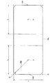
図2は断面形状が長方形の打抜きパンチ11Aを示すものである。この打抜きパンチ11Aにおいては、断面形状が四角形の短辺15Sを一辺とする正方形を想定し、この正方形の中心Pを中心として、この中心Pから短辺15Sと長辺15Lとの交わりの角Cまでの寸法より僅かに小さな寸法の半径RBで円を描いた場合の面取りを各角部に行うものである。
【0017】
断面形状が長方形の打抜きパンチ11Aの場合には、前記中心Pを中心として打抜きパンチ11Aを回動して研削加工を同時的に行う角部は、短辺15Sの両側に位置する角部である。
【0018】
【発明の効果】
以上のごとき説明より理解されるように、本発明によれば、打抜きパンチを回動して複数の角部を同時的に研削加工して面取りを行うものであるから、従来の面取り加工に比較して面取り加工が容易であると共に、複数の角部を同一形状、寸法に面取り加工することができ、結果として工具の長寿命化を図ることができるものである。
【0019】
また、面取り加工部分の円弧は大径の円弧であるので、ミクロジョイント加工を行った場合、ミクロジョイント部分の幅寸法をミクロジョイント部の全長に亘ってほぼ一定とすることができ、従来よりも応力集中を抑制できる良好なミクロジョイント加工を行うことができるものである。
【図面の簡単な説明】
【図1】本発明の第1の実施形態に係る打抜きパンチの断面形状を示す説明図である。
【図2】本発明の第1の実施形態に係る打抜きパンチの断面形状を示す説明図である。
【図3】従来の打抜きパンチの断面形状を示す説明図である。
【符号の説明】
1,11…打抜きパンチ
3,13…角部
5,15…面
7,17…ミクロジョイント部
3A,13A…円弧[0001]
BACKGROUND OF THE INVENTION
The present invention relates to a punching punch having a square or rectangular cross-sectional shape and a manufacturing method thereof, and more specifically, each corner of the quadrangle (a corner at the intersection of the surface) is chamfered in an arc shape. The present invention relates to a punching punch and a manufacturing method thereof.
[0002]
[Prior art]
There are various shapes such as a round shape, a triangular shape, and a quadrangular shape as the cross-sectional shape of a punching punch for punching a metal sheet. However, in a square punch, chipping is likely to occur at the corner portion. In general, a small chamfering process is performed.
[0003]
In a punch with a square cross-section, chamfering is conventionally performed on the corners, and the chamfering is not a flat (slope) chamfering, but a chamfered portion to reduce chipping. Chamfering is performed in an arc shape with a small radius so as to be rounded so as to eliminate. Since this type of chamfering is conventional, the dimension of the minute radius is not necessarily constant, and is generally about 0.1 mm to 0.3 mm.
[0004]
The chamfering of the corner in the square punching punch is customarily performed in consideration of the chipping of the corner and corresponding to the required processing accuracy. There is no literature showing appropriate values for chamfering of each corner.
[0005]
[Problems to be solved by the invention]
Conventionally, when chamfering each corner of a punching punch having a square cross-section, each surface of the
[0006]
Therefore, conventionally, in order to chamfer each corner, positioning for aligning the rotation center A of each
[0007]
Further, when a micro joint (a punching process that leaves a minute connecting portion between a workpiece and a product) is performed by the
[0008]
[Means for Solving the Problems]
The present invention has been made in view of the conventional problems as described above. The invention according to
[0009]
The invention according to claim 2 is a method of manufacturing a square punching punch having a quadrangular cross-sectional shape and a right angle formed by four corners, assuming a square having one side of the short side of the square. Is a method for manufacturing a square punching punch that simultaneously grinds a plurality of adjacent corners in an arc shape while rotating around the center of the center.
[0010]
The invention according to
[0011]
DETAILED DESCRIPTION OF THE INVENTION
Referring to FIG. 1, the
[0012]
More specifically, the radius RA is a radius that describes a circle circumscribing the
[0013]
The
[0014]
Therefore, it is easy to grind each of the four
[0015]
With the above-described configuration, when the joint portion between the workpiece and the product is subjected to micro joint processing, the portion of the
[0016]
FIG. 2 shows a
[0017]
In the case of the
[0018]
【The invention's effect】
As can be understood from the above description, according to the present invention, the punching punch is rotated to grind a plurality of corners simultaneously to perform chamfering, which is compared with conventional chamfering. Thus, chamfering is easy, and a plurality of corners can be chamfered to the same shape and size, and as a result, the tool life can be extended.
[0019]
Moreover, since the arc of the chamfered portion is a large-diameter arc, when microjoint processing is performed, the width dimension of the microjoint portion can be made substantially constant over the entire length of the microjoint portion. Good microjoint processing that can suppress stress concentration can be performed.
[Brief description of the drawings]
FIG. 1 is an explanatory view showing a cross-sectional shape of a punching punch according to a first embodiment of the present invention.
FIG. 2 is an explanatory view showing a cross-sectional shape of a punching punch according to the first embodiment of the present invention.
FIG. 3 is an explanatory view showing a cross-sectional shape of a conventional punching punch.
[Explanation of symbols]
DESCRIPTION OF
Claims (3)
Priority Applications (1)
| Application Number | Priority Date | Filing Date | Title |
|---|---|---|---|
| JP2003029089A JP4242168B2 (en) | 2003-02-06 | 2003-02-06 | Square punch and manufacturing method thereof |
Applications Claiming Priority (1)
| Application Number | Priority Date | Filing Date | Title |
|---|---|---|---|
| JP2003029089A JP4242168B2 (en) | 2003-02-06 | 2003-02-06 | Square punch and manufacturing method thereof |
Publications (2)
| Publication Number | Publication Date |
|---|---|
| JP2004237314A true JP2004237314A (en) | 2004-08-26 |
| JP4242168B2 JP4242168B2 (en) | 2009-03-18 |
Family
ID=32956357
Family Applications (1)
| Application Number | Title | Priority Date | Filing Date |
|---|---|---|---|
| JP2003029089A Expired - Fee Related JP4242168B2 (en) | 2003-02-06 | 2003-02-06 | Square punch and manufacturing method thereof |
Country Status (1)
| Country | Link |
|---|---|
| JP (1) | JP4242168B2 (en) |
Cited By (3)
| Publication number | Priority date | Publication date | Assignee | Title |
|---|---|---|---|---|
| JP2013131411A (en) * | 2011-12-21 | 2013-07-04 | Tokuriki Honten Co Ltd | Production method of electrical contact material and electrical contact material |
| JP2014231094A (en) * | 2013-05-30 | 2014-12-11 | 新日鐵住金株式会社 | Shearing processing method |
| CN118143119A (en) * | 2024-05-11 | 2024-06-07 | 常州华通新立地板有限公司 | Punching device with trimming function for machining steel floor |
Families Citing this family (1)
| Publication number | Priority date | Publication date | Assignee | Title |
|---|---|---|---|---|
| US7080755B2 (en) | 2004-09-13 | 2006-07-25 | Michael Handfield | Smart tray for dispensing medicaments |
-
2003
- 2003-02-06 JP JP2003029089A patent/JP4242168B2/en not_active Expired - Fee Related
Cited By (3)
| Publication number | Priority date | Publication date | Assignee | Title |
|---|---|---|---|---|
| JP2013131411A (en) * | 2011-12-21 | 2013-07-04 | Tokuriki Honten Co Ltd | Production method of electrical contact material and electrical contact material |
| JP2014231094A (en) * | 2013-05-30 | 2014-12-11 | 新日鐵住金株式会社 | Shearing processing method |
| CN118143119A (en) * | 2024-05-11 | 2024-06-07 | 常州华通新立地板有限公司 | Punching device with trimming function for machining steel floor |
Also Published As
| Publication number | Publication date |
|---|---|
| JP4242168B2 (en) | 2009-03-18 |
Similar Documents
| Publication | Publication Date | Title |
|---|---|---|
| JP4406752B2 (en) | Glass substrate end face processing apparatus and end face processing method | |
| JP4875273B2 (en) | Cutting insert for camshaft milling equipment | |
| KR19990083128A (en) | Method for chamfering a wafer | |
| WO2018061227A1 (en) | Cutting insert and cutting tool | |
| KR20150135185A (en) | Cbn cutting tool manufacturing method and cbn cutting tool | |
| JP2019042816A (en) | Cutting insert and cutting tool | |
| TW434099B (en) | Wafer, apparatus and method of chamfering wafer | |
| JP4242168B2 (en) | Square punch and manufacturing method thereof | |
| TWI684494B (en) | Grinding stone | |
| CN109070231B (en) | Stripping plate | |
| JP6476892B2 (en) | Multipoint diamond tools | |
| CN109475954A (en) | Wheel shape cutting cutter | |
| JP2012218083A (en) | Cutting tool, and method for manufacturing workpiece using the same | |
| JP5309748B2 (en) | Insert detachable cutter and cutting insert | |
| JP2010269381A (en) | Dresser | |
| JP4609286B2 (en) | Method and apparatus for chamfering circular holes | |
| JP2002079469A (en) | Grinding wheel | |
| JP6179879B1 (en) | Cutting inserts and cutting tools | |
| JP2013163235A (en) | Optical element machining tool and optical element manufacturing method | |
| JP2009154262A (en) | Grinding device | |
| KR102195461B1 (en) | Substrate grinding apparatus | |
| RU2773661C2 (en) | Cutting insert of square shape with curved additional and angular cutting edges, and rotating cutting tool | |
| JP2017035740A (en) | Chamfering wheel and chamfering method using the same | |
| JP2007000959A (en) | Two-face machining cast iron plate for monocrystal diamond cutting edge, two-face machining device, and two-face machining method | |
| JP2011251364A (en) | Grinding wheel and work processing method using this grinding wheel |
Legal Events
| Date | Code | Title | Description |
|---|---|---|---|
| A621 | Written request for application examination |
Free format text: JAPANESE INTERMEDIATE CODE: A621 Effective date: 20060126 |
|
| A977 | Report on retrieval |
Free format text: JAPANESE INTERMEDIATE CODE: A971007 Effective date: 20080919 |
|
| A131 | Notification of reasons for refusal |
Free format text: JAPANESE INTERMEDIATE CODE: A131 Effective date: 20080924 |
|
| A521 | Written amendment |
Free format text: JAPANESE INTERMEDIATE CODE: A523 Effective date: 20081114 |
|
| TRDD | Decision of grant or rejection written | ||
| A01 | Written decision to grant a patent or to grant a registration (utility model) |
Free format text: JAPANESE INTERMEDIATE CODE: A01 Effective date: 20081209 |
|
| A01 | Written decision to grant a patent or to grant a registration (utility model) |
Free format text: JAPANESE INTERMEDIATE CODE: A01 |
|
| A61 | First payment of annual fees (during grant procedure) |
Free format text: JAPANESE INTERMEDIATE CODE: A61 Effective date: 20081224 |
|
| FPAY | Renewal fee payment (event date is renewal date of database) |
Free format text: PAYMENT UNTIL: 20120109 Year of fee payment: 3 |
|
| R150 | Certificate of patent or registration of utility model |
Ref document number: 4242168 Country of ref document: JP Free format text: JAPANESE INTERMEDIATE CODE: R150 Free format text: JAPANESE INTERMEDIATE CODE: R150 |
|
| FPAY | Renewal fee payment (event date is renewal date of database) |
Free format text: PAYMENT UNTIL: 20120109 Year of fee payment: 3 |
|
| FPAY | Renewal fee payment (event date is renewal date of database) |
Free format text: PAYMENT UNTIL: 20130109 Year of fee payment: 4 |
|
| FPAY | Renewal fee payment (event date is renewal date of database) |
Free format text: PAYMENT UNTIL: 20130109 Year of fee payment: 4 |
|
| FPAY | Renewal fee payment (event date is renewal date of database) |
Free format text: PAYMENT UNTIL: 20140109 Year of fee payment: 5 |
|
| S533 | Written request for registration of change of name |
Free format text: JAPANESE INTERMEDIATE CODE: R313533 |
|
| R350 | Written notification of registration of transfer |
Free format text: JAPANESE INTERMEDIATE CODE: R350 |
|
| S533 | Written request for registration of change of name |
Free format text: JAPANESE INTERMEDIATE CODE: R313533 |
|
| R350 | Written notification of registration of transfer |
Free format text: JAPANESE INTERMEDIATE CODE: R350 |
|
| LAPS | Cancellation because of no payment of annual fees |