JP2004234724A - Tray and disk rotating device - Google Patents
Tray and disk rotating device Download PDFInfo
- Publication number
- JP2004234724A JP2004234724A JP2003020107A JP2003020107A JP2004234724A JP 2004234724 A JP2004234724 A JP 2004234724A JP 2003020107 A JP2003020107 A JP 2003020107A JP 2003020107 A JP2003020107 A JP 2003020107A JP 2004234724 A JP2004234724 A JP 2004234724A
- Authority
- JP
- Japan
- Prior art keywords
- disk
- tray
- optical disk
- rotation
- main body
- Prior art date
- Legal status (The legal status is an assumption and is not a legal conclusion. Google has not performed a legal analysis and makes no representation as to the accuracy of the status listed.)
- Pending
Links
Images


Classifications
-
- G—PHYSICS
- G11—INFORMATION STORAGE
- G11B—INFORMATION STORAGE BASED ON RELATIVE MOVEMENT BETWEEN RECORD CARRIER AND TRANSDUCER
- G11B17/00—Guiding record carriers not specifically of filamentary or web form, or of supports therefor
- G11B17/02—Details
- G11B17/04—Feeding or guiding single record carrier to or from transducer unit
- G11B17/05—Feeding or guiding single record carrier to or from transducer unit specially adapted for discs not contained within cartridges
- G11B17/053—Indirect insertion, i.e. with external loading means
- G11B17/056—Indirect insertion, i.e. with external loading means with sliding loading means
-
- G—PHYSICS
- G11—INFORMATION STORAGE
- G11B—INFORMATION STORAGE BASED ON RELATIVE MOVEMENT BETWEEN RECORD CARRIER AND TRANSDUCER
- G11B33/00—Constructional parts, details or accessories not provided for in the other groups of this subclass
- G11B33/02—Cabinets; Cases; Stands; Disposition of apparatus therein or thereon
- G11B33/08—Insulation or absorption of undesired vibrations or sounds
Abstract
Description
【0001】
【発明の属する技術分野】
本発明は、トレイ及びディスク回転装置に係り、更に詳しくは、光ディスクドライブ装置などのディスク回転装置の本体内へのディスクのローディング及び本体内から外部へのディスクのアンローディングに用いて好適なトレイ、及び該トレイを備えたディスク回転装置に関する。
【0002】
【従来の技術】
近年、情報機器のデジタル化とこれに伴うマルチメディア機器の急速な発展によって、取り扱う情報量(データ量)が急増している。そのため、各種情報記録媒体に対しても更なる大容量化の要請がなされている。このため、コンピュータ、音響機器又は映像機器においては、情報記録媒体として、コンパクトディスク(Compact Disc:以下「CD」と略述する)や、CDの約7倍相当のデータをCDと同じ直径のディスクに記録可能としたDVD(Digital Versatile Disc)等の光ディスクが用いられている。この光ディスクに対する情報の記録及び再生のため、ディスクを回転させながら当該ディスクの表面にレーザビームを照射し、ディスクの記録面上にマーク領域及びスペース領域を形成することによって情報を記録したり、ディスクから反射された光を光電検出してディスク表面上に記録された情報を読み取ったりする光ディスクドライブ装置が用いられる。
【0003】
光ディスクドライブ装置は、内部に光ピックアップを備えた装置本体と、装置本体の前面に設けた開口から内外へ進退可能に支持され且つ光ディスクを着脱自在に保持する受け皿部を備えたトレイと、光ディスクを受け皿部に保持したトレイを装置本体内に装填したときに受け皿部上の光ディスクを回転可能に支持する光ディスク回転機構と、光ピックアップ駆動機構および光ディスク回転機構を保持するための構造体と、さらにトレイを装置本体前面に引き出し又は収納するための開口部を有するフロントパネルを備えた構成を有している。
【0004】
光ディスクドライブ装置は、上記のように記録及び再生の対象となる光ディスクの記憶容量が大きいことに加え、単位記憶容量あたりの単価が安いことから、パソコンの主な周辺機器としての開発が進められ、データの読み出し速度は高速化の一途を辿っている。
【0005】
一般に、データの読み出し速度を大きくする方法として、ディスクの回転数を大きくする方法が採られている。初期の光ディスクドライブ装置の基準回転速度(200rpm)を1とすると、現行では、32倍速(6400rpm)以上のものが一般的となっており、最近では50倍速(10000rpm)を超えるものも多く存在するようになっている。
【0006】
また、光ディスクドライブ装置の業界では、パーソナルコンピュータの小型化に伴って、ディスクドライブ装置の狭いスペース内への設置を目的とした縦置き使用を行うことが一般的となってきた。光ディスクドライブ装置を縦置きにして使用する場合、光ディスクを装置内にローディングする際(及びアンローディングする際)にトレイの皿状の凹所(受け皿部と呼ばれる)のみでディスクを保持することとすると、ディスクが自重ですべり落ち、あるいは傾倒してしまい、使用が困難である。このため、縦置き使用を想定した光ディスクドライブ装置では、トレイの受け皿部周辺に、光ディスクの外周の一部に対して多少の遊びをもって係合する、ディスクの滑り落ち又は傾倒を防止する傾倒防止用の機構(例えば爪又はフック)が設けられているものが一般的である。
【0007】
例えば、トレイの受け皿部周辺に、別個に製造した可動式のフックを備え付け、縦置き使用時のローディングに対応したディスク装置が知られている(例えば、特許文献1等参照)。
【0008】
この他、一端部がトレイ受け皿周辺部に固定された状態の弾性舌片を有し、該弾性舌片の他端部が保持片のU字状部に嵌合可能な構成とすることで、別部材を用いることなく、縦置き使用時のローディングに対応したディスクプレイヤも知られている(例えば、特許文献2等参照)。
【0009】
【特許文献1】
特開平6−251479号公報
【特許文献2】
特開2001−006246号公報
【0010】
【発明が解決しようとする課題】
光ディスクドライブ装置を縦置きにしてローディング動作を行うためには、トレイの受け皿部周辺の傾倒防止用の爪又はフック(以下、「傾倒防止用爪」と総称する)は必要であるが、該傾倒防止用爪は、ディスクの回転環境(以下、「ディスク回転域」とも記述する)内では渦(カルマン渦)の発生源となる突起物となる。上記のカルマン渦(又はカルマンの渦列)の発生による空気の振動が、ディスク回転による風切り音に他ならない。すなわち、光ディスクドライブ装置の縦置き時の傾倒防止用爪は、その風切り音を増大させるものである。ディスク回転に伴うカルマン渦の発生頻度は回転速度がある範囲内では、回転周波数(回転速度)に応じたものとなり、回転周波数に応じて風切り音は変化する。
【0011】
実際、光ディスクドライブ装置の騒音は、単倍速、すなわち10倍速(2000rpm)未満の回転数では、それほど気になるものではなかったが、10倍速以上、特に、32倍速以上の回転数では、大きな騒音となっている。
【0012】
この場合、縦置き時の傾倒防止用爪がディスク回転域内に常時突出している場合のみならず、上記特許文献1や特許文献2のように、可動式の傾倒防止用爪を有する場合であっても、縦置きで使用している間は、ディスクドライブ装置内に取り込まれた後でも、その爪はディスクの回転域内に突出しているので、ディスク回転による風切り音が増大する原因となっている。
【0013】
従来、この騒音対策としては、トレイが光ディスクドライブ装置内に収容された際に、フロントパネルの開口部からディスクドライブ装置内で生じる騒音が外部に漏れ出さないような対策を施していた。例えば、ディスクドライブ装置とトレイの外側の端部に開口部を閉塞するドアを一体的に取り付け、このドアと光ディスクドライブ装置の本体との間に、シール部材を設けるなどの対策である。
【0014】
しかしながら、この部分は、ユーザによる視認が常に可能な部分であるので、ディスクドライブ装置の外観に少なからず影響を与えるのみならず、ディスク回転が高速化した最新の光ディスクドライブ装置では、騒音対策として不十分なものとなっている。
【0015】
本発明は、かかる事情の下になされたものであり、その第1の目的は、ディスク回転装置のディスクのローディング及びアンローディグに用いた場合に、ディスクの回転に伴う騒音を低減させることが可能なトレイを提供することにある。
【0016】
本発明の第2の目的は、装置の外観を損なうことなく、ディスクの回転に伴う騒音を低減することが可能なディスク回転装置を提供することにある。
【0017】
【課題を解決するための手段】
請求項1に記載の発明は、ディスク回転装置本体に装着され、前記ディスク回転装置本体を構成する筐体内のディスク回転位置に対して前記筐体に形成された開口部を介してディスクを搬入する際及び前記回転位置から前記開口部を介して外部の出し入れ位置に前記ディスクを搬出する際に用いられるトレイであって、ディスクを収容可能な凹所が形成されたトレイ本体部と;前記凹所内に実質的にセットされた前記ディスクの外周縁近傍の一部に対向可能な状態で前記トレイ本体部の前記凹所の周壁から内側に向けて突設された段差が存在しない滑らかな先端形状を有する特定の爪部を含む少なくとも1つのディスク傾倒防止用の爪部と;を備えるトレイである。
【0018】
本明細書において、単に「ディスク」と記述するときは、「ディスク」は、光ディスク等の情報記録媒体のみを意味するものではなく、通常と同様、「円盤」又は「円板状の物体」を意味する。また、本明細書において、「ディスク傾倒防止用の爪部」とは、トレイ本体部がほぼ鉛直となるディスク回転装置の縦置き使用時に、凹所内に実質的にセットされたディスクの脱落、傾倒を防止するための爪又はフックなどを意味する。
【0019】
これによれば、ディスク傾倒防止用の爪部として、トレイ本体部の凹所内に実質的にセットされたディスクの外周縁近傍の一部に対向可能な状態でトレイ本体部の凹所の周壁から内側に向けて突設された段差が存在しない滑らかな先端形状を有する特定の爪部を含んでいる。この場合、ディスク傾倒防止用の爪部は、この特定の爪部と、従来の爪部と同様の爪部とを含んでいても良いし、特定の爪部のみであっても良い。また、その数も、ディスク回転装置の縦置き使用時にディスクの傾倒を防止できれば、任意で良い。
【0020】
いずれにしても、特定の爪部は、段差が存在しない滑らかな先端形状を有するので、従来の爪と比べてディスクの回転に伴って発生する気流中での抵抗が小さく、カルマン渦の発生度合いを低減できる。従って、ディスクの回転に伴う風切り音の発生を抑制することが可能となり、これにより、ディスクの回転に伴う騒音を低減させることが可能となる。このディスク回転に伴う騒音の低減は、ディスク回転装置の縦置き使用時及びトレイを水平に向けるディスク回転装置の横置き使用時のいずれであっても可能であることは言うまでもない。
【0021】
この場合において、請求項2に記載のトレイの如く、前記ディスク傾倒防止用の爪部は、複数設けられ、全ての爪部が前記特定の爪部であることとすることができる。かかる場合には、より一層ディスクの回転に伴う風切り音の発生を低減させることができる。
【0022】
上記請求項1及び2に記載の各トレイにおいて、特定の爪部の段差が存在しない滑らかな先端形状としては、種々の形状が考えられるが、例えば、請求項3に記載のトレイの如く、前記特定の爪部は、その先端部の形状が、円の一部又は楕円の一部を構成する弧状であることとすることができる。
【0023】
上記請求項1〜3に記載の各トレイにおいて、請求項4に記載のトレイの如く、前記ディスク傾倒防止用の爪部として、前記ディスクの外周縁近傍のほぼ全域に対向可能となるように設けられた、複数の前記特定の爪部を有することとすることができる。
【0024】
上記請求項1〜4に記載の各トレイにおいて、請求項5に記載のトレイの如く、前記特定の爪部は、少なくとも前記ディスクに対向する側の面が曲面とされていることとすることができる。かかる場合には、特定の爪部の先端部近傍の断面形状が流線型に近い形状となるので、ディスク回転に伴う気流に対する抵抗をより小さくすることが可能となり、風切り音をより一層低減することができる。
【0025】
請求項6に記載の発明は、ディスクを所定の回転位置にて回転駆動するディスク回転装置であって、開口部が形成された筐体を含んで構成されるディスク回転装置本体と;前記筐体内の前記ディスク回転位置に対して前記開口部を介して前記ディスクを搬入する第1位置と前記回転位置から前記開口部を介して外部の出し入れ位置に前記ディスクを搬出する第2位置との間で移動可能に前記ディスク回転装置本体に装着された請求項1〜5のいずれか一項に記載のトレイと;を備えるディスク回転装置である。
【0026】
これによれば、請求項1〜5のいずれか一項に記載のトレイを備えているので、いわゆる縦置き、横置きのいずれの使用時であっても、ディスク回転装置本体内でのディスクの回転駆動による風切り音の発生が抑制されるので、騒音の発生を低減することが可能である。また、この場合、風切り音の低減のために、ディスク回転装置本体の筐体の開口部周辺に対して特別な防音対策を施す必要がない。従って、装置の外観を損なうことなく、ディスクの回転に伴う騒音を低減した、いわゆる静音設計のドライブ装置が提供される。
【0027】
この場合において、請求項7に記載のディスク回転装置の如く、前記ディスクは、情報記録媒体であり、前記筐体内に配置され、前記情報記録媒体に対する情報の記録、再生及び消去のうち、少なくとも再生を行うヘッド部を更に備えることとすることができる。
【0028】
この場合において、請求項8に記載のディスク回転装置の如く、前記情報記録媒体は光ディスクであり、前記ヘッド部は光ピックアップであることとすることができる。すなわち、本発明のディスク回転装置が、光ディスクドライブ装置であることとすることができる。
【0029】
【発明の実施の形態】
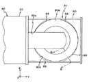
以下、本発明の一実施形態を図1〜図7に基づいて説明する。図1には、本発明のディスク回転装置の一実施形態に係る光ディスクドライブ装置(以下、「ドライブ装置」と略述する)100の概略斜視図が示されている。
【0030】
この図1に示されるドライブ装置100は、ディスク(及び情報記録媒体)としての光ディスク10の搬入及び搬出を行うとともに、搬入された光ディスク10に対する情報の記録及び再生(及び消去)などを行う。光ディスク10としては、例えばCD−R(CD−recordable)、CD−RW(CD−rewritable)などのCD系の規格に準拠した情報記録媒体が用いられる。
【0031】
ドライブ装置100は、ヘッド部としての光ピックアップPU(図5参照)等が内蔵され、光ディスク10への情報の記録、光ディスク10に記録されている情報の再生(及び消去)などを行うディスク回転装置本体としてのドライブ装置本体90と、該ドライブ装置本体90を構成する箱型の筐体91に装着されたトレイ81とを備えている。
【0032】
前記トレイ81は、図1中の矢印A、A’方向(±Y方向)に往復移動可能にドライブ装置本体90の筐体91に装着されており、筐体91内部の後述するディスク回転位置に光ディスク10をローディング(搬入)する際、及びそのディスク回転位置からドライブ装置本体90外部のディスク出し入れ位置に光ディスク10をアンローディング(搬出)する際に用いられる。
【0033】
トレイ81は、トレイ本体部としてのトレイ本体80及び該トレイ本体80の一端(+Y側の端部)に取り付けられたドア89等を備えている。この場合、トレイ81が矢印A’方向の移動限界位置まで移動した際に、ドア89がドライブ装置本体90の筐体91を構成するフロントベゼル25の開口部25aに嵌合し、ドライブ装置100の前面部が見かけ上一枚板となるようになっている。なお、トレイ81の具体的な構成等については後に更に詳述する。
【0034】
前記筐体91は、ドライブ装置100の要部の分解斜視図である図2に示されるように、底壁及該底壁から立ち上がった3方(+Z側、−Z側及び−Y側)の側壁を有するベース21と、該ベース21の3方の側壁及び上面を覆う状態で取り付けられるトップカバー20と、これら両者により構成される、前面(+Y側の面)が開口した箱型の筐体の前面を塞ぐ状態で取り付けられるフロントベゼル25とから構成される。
【0035】
前記トップカバー20及びベース21は、外部からの衝撃に耐えられるように、例えば金属板等を加工して形成される。また、前記フロントベゼル25は、例えばプラスチックにより形成され、+X側寄りの部分に矩形(長方形)の開口部25aが形成されている。
【0036】
図1に戻り、フロントベゼル25の開口部25aの近傍には、トレイ81を出し入れするイジェクトボタン27が設けられている。前記トレイ81は、筐体91内のディスク回転位置に対して開口部25aを介して光ディスク10を搬入する第1位置と回転位置から開口部25aを介して外部の出し入れ位置に光ディスク25を搬出する第2位置との間で移動可能に、ドライブ装置本体90(筐体91)に装着されている。この場合、イジェクトボタン27が押されると、その情報が、不図示のコントローラに送られ、該コントローラが所定の基準に従って後述するトレイ駆動用のモータを駆動するようになっている。
【0037】
ドライブ装置100の内部構成部品は、前述したベース21内に収容される。このベース21の内部には、図2に示されるように、メカシャーシ22が配置され、該メカシャーシ22の四隅近傍には防振部23がそれぞれ設けられている。奥側(−Y側)の2つの防振部23は、螺子により不図示の固定部材に固定されている。残りの防振部23は、メカシャーシ22を−Y側端部近傍の支軸を中心に起伏回動させてメカシャーシ22の+Y側部分をX軸方向に上下させる不図示のアップダウン機構の一部に螺子止めされている。また、メカシャーシ22の+Y側部分には、回転駆動機構としてのターンテーブル32が設けられている。このターンテーブル32の回転中心部には、光ディスク10を保持するためのボス32aが設けられている。ターンテーブル32の駆動源は、不図示のスピンドルモータである。
【0038】
ターンテーブル32に対向して、クランパ36が設けられ、該クランパ36は、ベース21の上部にその長手方向の両端が固定されたクランパプレート35に保持される。
【0039】
この場合、光ディスク10がターンテーブル32上にローディングされた状態で、前述のアップダウン機構によりメカシャーシ22がアップされると、ディスククランパ36によって、光ディスク10がターンテーブル32に押し付けられ、ターンテーブル32及びディスククランパ36によって光ディスク10が狭持されるようになっている。そして、この状態で、ターンテーブル32が不図示のスピンドルモータによって回転駆動されることにより、光ディスク10が回転されるようになっている。本実施形態では、このようにして光ディスク10の回転が行われるので、前述のディスク回転位置は、ターンテーブル32の位置を指す。
【0040】
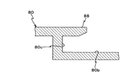
次に、前記トレイ81の構成等について図3及び図3のB−B線断面図である図4に基づいて説明する。
【0041】
図3には、トレイ81の平面図が示されている。トレイ81は、例えばプラスチック等から構成され、図3に示されるように、トレイ81の前面(+X側面)には段つきのほぼ円形の凹部80bが形成されている。このうち、1段目の凹部には、例えば12センチCDなどの光ディスクがセットされ、2段目の凹部には、例えば8センチCDなどの光ディスクがセットされるようになっている。なお、以下においては、これらの凹部をまとめて「トレイ受け皿部80b」と呼ぶものとする。
【0042】
また、トレイ81には、図3におけるX軸方向に貫通して開口80aが形成されている。この開口80aは、トレイ81をドライブ装置本体90内に収納した際に、トレイ81がターンテーブル32や、光ピックアップPUなどに対して機械的に干渉するのを防止できるような形状とされている。また、トレイ81の裏面(−X側の面)の±Z側端部近傍には、不図示の溝部がY軸方向に沿って形成されており、更に、トレイ81の−Z側の側壁の内面には、不図示のラックがX軸方向に延設されている。
【0043】
前記トレイ受け皿部80bの周縁部を構成する壁(以下、「周辺部壁」と呼ぶ)80cには、図3及び図4に示されるように、その下側(−Z側)部分及び上側(+Z側)部分にそれぞれトレイ受け皿部80bの内側に突設する状態で特定の爪部としての庇部88が4ヶ所形成されている。各庇部88は、段差が存在しない滑らかな先端形状を有している。具体的には、各庇部88の先端部の形状が、円の一部又は楕円の一部を構成する弧状である。なお、庇部88は、それぞれその±Z方向の端部近傍ほどトレイ受け皿部80bの内側方向に多く突出しており、Z軸方向の中央部近傍ほどその突出量は少なくなっている。これは、縦置き使用時にディスクの脱落及び傾倒を防止するため、使用時に下側に位置する可能性のある部分の庇部を他の部分に比べて大きくしているのである。
【0044】
次に、トレイ81を図1の矢印A、A’方向に駆動するトレイ駆動機構30について、カバー20を一部破断して示す図5に基づいて説明する。
【0045】
前記トレイ駆動機構30は、回転軸41aを時計回り又は反時計回りに回転駆動する電動機(モータ)41と、該モータ41の回転軸41aに固定されたプーリー43と、モータ41近傍に設けられた複数のギアから成るギア列47と、プーリー43の回転をギア列47を構成する1つのギア47bに伝達する駆動ベルト45とを備えている。ギア列47を構成するギアのうちの最も−Z側に位置するギア47aは、トレイ81に設けられた前記ラックと噛み合い、一種のピニオンとして機能する。
【0046】
このように構成されるトレイ駆動機構30では、モータ41の回転軸41aの回転により、プーリー43、駆動ベルト45を介してギア列47を構成する個々のギアが駆動される。そして、−Z方向端部に位置するギア47aが反時計回り又は時計回りに回転駆動され、ラックを介してトレイ81を矢印A方向又は矢印A’方向に駆動するようになっている。この場合、プーリー43、駆動ベルト45、及びギア列47によって、モータ41(より正確には回転軸41a)の回転を減速してギア47a、さらにはラックに伝達する減速機構が構成されている。
【0047】
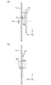
ここで、トレイ81が矢印A方向に所定距離だけ駆動され、図5に点線にて示される位置に達すると、ギア列47の近傍に設けられたストッパ52が、トレイ81の側面に形成された不図示の切り欠きに係合し、トレイ81の更なる矢印A方向への移動が阻止されるようになっている。この状態では、トレイ81のトレイ受け皿部80bがドライブ装置本体90の外部に完全に露出するため、ユーザはトレイ受け皿部80bへ光ディスク10をセットし、あるいはトレイ受け皿部80bから光ディスク10を取り出したりすることができる。従って、以下では、トレイ81の図5に点線で示される位置を「ディスク着脱位置」と呼ぶものとする。このディスク着脱位置では、図6(A)に示されるように、光ディスク10は、トレイ受け皿部80bの中心よりやや下側(−Z側)にずれた状態で保持されることになる。
【0048】
また、トレイ81が矢印A’方向に最大限に移動し、ドライブ装置本体80内に完全に収容された状態では、トレイ81に形成された開口80aを形成する+Y側の壁に対して僅かに隙間を空けた位置にターンテーブル32が位置するようになっており、トレイ受け皿部80b上に光ディスク10がセットされている場合には、光ディスク10に対する情報の記録、並びに光ディスク10に記録された情報の再生及び消去が可能となっている。従って、以下においては、トレイ81のこの状態での位置を「記録・再生位置」と呼ぶものとする。この記録・再生位置では、図6(B)に示されるように、ボス32aが光ディスク10の中心孔に嵌合するようになっている。
【0049】
この場合、前述のように光ディスク10がトレイ81のやや下側にずれているため、ターンテーブル32の高さ(Z方向の位置)と光ディスク10の中心孔の高さが一致しないこととなる。しかしながら、図7(A)に示されるように、ボス32aの先端がテーパー状に加工されているため、ターンテーブル32の高さと中心孔の高さとが一致しない場合でも、テーパー加工部分がガイドの役割を果たし、図7(B)に示されるように光ディスク10の回転中心とターンテーブル32の回転中心とがほぼ一致するように、光ディスク10をターンテーブル32によって保持可能となっている。より具体的には、ボス32aの先端部と光ディスクを実際に保持する部分との半径差ΔL1が、光ディスク10の中心孔の中心とターンテーブル32の回転中心との高さ差ΔL2よりも大きい場合であれば、ボス32aによる光ディスク10の保持が可能となる。なお、実際にはターンテーブル32は前記アップダウン機構によりX軸方向のみに駆動されるので、Z軸方向には光ディスク10が移動することになるが、図7(B)では、図示の便宜上ターンテーブル32がZ軸方向にも動くかのように示している。
【0050】
図5に戻り、ターンテーブル32の−Y側には前記光ピックアップPUが配置されている。この光ピックアップPUは、光ディスク10の記録面にレーザビームを照射するとともに、記録面からの反射光を受光する。また光ピックアップPUは、光ピックアップPUを構成する対物レンズLSを光ディスク10に対してY軸方向及びX軸方向に駆動するための駆動機構を備えている。
【0051】
次に、上記のようにして構成されたドライブ装置100の動作について簡単に説明する。
【0052】
ユーザにより、図1に示されるフロントベゼル25に設けられたイジェクトボタン27が押されると、前述の如くして不図示のコントローラによりモータ41(より正確には回転軸41a)が所定方向、例えば反時計回りに回転駆動される。このモータ41(より正確には回転軸41a)の回転はプーリー43、駆動ベルト45、ギア列47(−Z端に位置するギア47aを除くギア)を介してトレイ81のラックに噛み合った状態のギア47aを反時計回りに回転駆動する。これにより、トレイ81は、図5の矢印A方向に駆動される。そして、所定距離駆動されるとトレイ81の側面に形成された切り欠きにストッパ52が係合し、トレイ81が前記ディスク着脱位置に位置決めされる。このディスク着脱位置にトレイが位置決めされると、不図示のセンサ(又はリミットスイッチ)がこれを検知し、その検知信号が不図示のコントローラに伝達され、コントローラによってモータ41が停止される。
【0053】
トレイ81がディスク着脱位置にある状態で、ユーザにより光ディスク10がトレイ81のトレイ受け皿部80bにセットされ(あるいは、既にトレイ受け皿部80bに光ディスクがセットされている場合には、新たな光ディスク10との交換がなされ)、その後、ユーザによりイジェクトボタン27が押される、あるいはトレイ81が矢印A’方向に僅かに押されると、これらの動作が不図示のコントローラに伝達され、コントローラによってモータ41は、前記所定方向とは反対方向、例えば時計回りに回転駆動される。これにより、ギア47aが時計回りに回転駆動され、トレイ81が矢印A’方向へと駆動される。
【0054】
そして、トレイ81が前記記録・再生位置まで移動すると、ボス32aの+X側に光ディスク10の中心孔が位置することとなる。このとき、ターンテーブル32は、前記アップダウン機構により所定位置まで上昇駆動され、ターンテーブル32とディスククランパ36とにより前述のようにして光ディスク10が挟持される。次いで、コントローラによりスピンドルモータが回転されると同時に光ピックアップPUからレーザビームが照射され、光ディスク10から反射された光の検出、及び該検出された光の電気信号への変換などの処理を経て、光ディスク10のリード・イン領域に記録されている情報が読み取られ、その後コントローラによりターンテーブル32は停止される。
【0055】
その後、ユーザによる動作開始指示に応じて、光ディスク10が回転駆動されるとともに、光ピックアップPUからレーザビームが照射され、光ディスク10への情報の記録、並びに光ディスク10に記録されている情報の再生及び消去が実行される。
【0056】
ところで、前述したように、上記動作に伴って光ディスク10が回転駆動される場合の、該回転駆動に伴う風切り音がドライブ装置100からの騒音に与える影響が非常に大きいことがわかっている。この風切り音の主たる発生要因は、前述のカルマン渦であるから、このカルマン渦列が形成され難くすることが望ましい。
【0057】
そこで、本実施形態では、ドライブ装置100を縦置きに使用した際に、光ディスク10の傾倒防止用爪として、トレイ受け皿部80bの上部側及び下部側に段差が存在しない滑らかな先端形状を有する庇部88を設けることとしている。この庇部88によれば、光ディスク10の回転に伴う空気の流れの方向に対して抗するような部分がほとんど存在しないので、カルマン渦列が形成され難くなり、風切り音の発生が極力抑制されることとなる。
【0058】
ここで、発明者は、本実施形態に係るドライブ装置100を用いて、従来から比較的多く用いられている傾倒防止用爪(例えば、フック、弾性舌片等)を備える光ディスクドライブ装置に対する騒音の低減効果について実験を行った。
【0059】
具体的には、光ディスクを40倍速(回転数8000rpm)で回転させ、ユーザ位置(オペレータ位置)における音圧レベルを測定することとした。ここでは、人間の耳の感度が鋭い帯域の音についての音圧レベル、すなわち通常の騒音レベルとして用いられる「A特性音圧レベル(単位dB(A))」を測定するものとした。
【0060】
この結果、従来の光ディスクドライブ装置におけるA特性音圧レベルが平均値として46dB(A)であったのに対し、本実施形態に係るドライブ装置100では、平均値として44dB(A)であり、明らかな違いがあった。すなわち、本実施形態に係るドライブ装置100を用いることにより、人の耳に聞こえる騒音は、15〜20%低減されることとなることが判明した。
【0061】
以上詳細に説明したように、本実施形態のドライブ装置100によると、光ディスクの回転軸をほぼ水平方向に維持して使用する(すなわち、いわゆる「縦置き」で使用する)際に、光ディスクの傾倒防止用爪としてトレイ81に設けられた、光ディスクの外縁部の少なくとも一部を遊嵌する複数の庇部88が、光ディスク10の回転方向に対して滑らかな形状とされているので、光ディスクの回転に伴って発生する気流と庇部との間の抵抗が低減され、これにより、光ディスクの回転に伴う風切り音の発生及び増幅が極力抑制されることとなる。また、ディスクの回転軸をほぼ鉛直方向に維持して使用する(すなわち、いわゆる「横置き」で使用する)場合であっても、同様に、庇部による風切り音の発生及び増幅は極力抑制されるようになっている。この場合、トレイ81は、使用時にはドライブ装置本体内に収容されるので、その外観に影響を与えることも無い。すなわち、本実施形態のドライブ装置によると、その外観に影響を与えることなく、その使用状態に関わらず、騒音の発生を極力低減することが可能となっている。
【0062】
なお、上記実施形態では、光ディスク10を保持する部分、すなわち±Z側について庇部を多めにとることとしたが、全体的に同一量だけ突出した庇部を設けることとしても良い。
【0063】
また、上記実施形態では、トレイ81のZ軸方向両端部近傍及びY軸方向両端部近傍には庇部を設けないこととしたが(図3等参照)、これに限らず、設計上可能であれば、全周にわたって庇部を設けることとしても良く、このように全周にわたって庇部を設ける場合には、その庇部に遮音壁としての効果をも持たせることが可能となる。
【0064】
なお、上記実施形態では、ドライブ装置100の使用態様に対応するため、図3における+Z側及び−Z側のいずれにも庇部を設けることとしたが、例えば、図3に示される方向でのみ光ディスクドライブ装置が使用されるのであれば、庇部は、+Z側に設ける必要が無く、−Z側にのみ設けることとすれば足りる。
【0065】
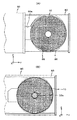
また、上記実施形態では、ドライブ装置100を縦置きで使用する際に、光ディスク10を保持するために必要な部分、すなわちトレイ受け皿部80bの下側及び上側の部分にのみ庇部が設けられるものとして説明したが、本発明がこれに限られるものではなく、例えば図8に示されるように、トレイ受け皿部80bの周辺部壁80cの全周にわたって、トレイ受け皿部80bの内側に突設する状態で、庇部88’を設けることとしても良い。このようにしても、風切り音の発生が極力抑制されるので、従来に比べてディスクドライブ装置から発生する騒音を小さくすることが可能となる。図9(A)には、図8のC−C線断面図が示されており、図9(B)には、図8のD−D線断面図が示されている。これらの図からわかるように、前記庇部88’は、周辺部壁80cのほぼ全周にわたって形成されているが、その±Z端部近傍ほどトレイ受け皿部80bの内側方向に多く突出しており(図9(B)参照)、Z軸方向中央部近傍ほどその突出量は少なくなっている。これは、縦置き使用時にディスクの脱落及び傾倒を防止するため、使用時に下側に位置する可能性のある部分の庇部を他の部分に比べて大きくしているのである。
【0066】
また、上記実施形態では、庇部の先端部の形状として円の一部又は楕円の一部を構成する弧状である場合について説明したが、光ディスクの回転方向に対して滑らかな形状であって、光ディスクの回転により発生する気流と庇部との間の抵抗が低減される形状であれば、その他、種々の形状を採用することは可能である。
【0067】
なお、上記実施形態では、庇部の全てを光ディスクの回転方向に対して滑らかな形状(円弧形状)とする、すなわち、傾倒防止用の爪部の全てが特定の爪部である場合について説明したが、本発明がこれに限られるものではなく、少なくとも1つ(一部)の爪部を庇部(すなわち、特定の爪部)とし、残りを従来の爪部としても、風切り音を低減することは可能である。
【0068】
なお、上記実施形態では、トレイ81の周辺部壁80cに庇部を設けることとしたが、本発明はこれに限らず、周辺部壁80c自体を庇状に突出させ、その庇状の周辺部壁80cに、光ディスクの回転方向に対して滑らかな形状を有する突起部を更に設けることとしても良い。
【0069】
なお、上記実施形態では、トレイ81を駆動する手段としてモータ41を駆動源とする駆動機構30を用いる場合について説明したが、本発明がこれに限られるものではなく、例えばモータ以外のアクチュエータを用いた駆動機構によってトレイを駆動しても良いし、あるいは手動にてトレイを移動させることとしても良い。また、イジェクトボタン27をユーザが押すことにより、トレイ81の開閉ロックが解除され、トレイ81が僅かにドライブ装置本体90から飛び出すようにし、該飛び出した状態のトレイ81をユーザが、外部に引き出すような構成を採用しても良い。
【0070】
また、上記実施形態では、イジェクトボタン27をユーザが押すことにより、トレイ81の出し入れを行う場合について説明したが、これに限らず、例えばドライブ装置100の上位装置(例えばパソコン)からの指示によりトレイ81の出し入れを行っても良い。
【0071】
また、上記実施形態では、ドライブ装置100及びそのローディング機構が、CD系の規格に準拠した光ディスクに対応した場合について説明したが、これに限らず、例えばDVD系の規格に準拠した光ディスクやレーザディスクLDの規格に準拠した光ディスクに対応するものであっても良い。さらに、CD系の規格に準拠した光ディスク及びDVD系の規格に準拠した光ディスクの両方に対応するドライブ装置であっても良い。要は、光ディスクに対する情報の記録、再生及び消去のうちの少なくとも再生を行うドライブ装置であれば、いずれの光ディスクであっても良い。また、情報記録媒体は、光ディスク以外の媒体であっても良い。要は、トレイにセット可能で、そのトレイを用いてローディング、アンローディングされるものであれば、その他の如何なる種類の情報記録媒体であっても良い。
【0072】
また、ドライブ装置は、ディスクの搭載面が水平面に垂直となる、いわゆる縦置きタイプに限らず、ディスクの搭載面が水平面と一致するようないわゆる横置きタイプを採用することも可能である。
【0073】
また、本発明のトレイはドライブ装置に限らず、平板状のディスク(円板)を回転する装置であれば、種々の装置に採用することが可能であり、平板状のディスクとしては、情報記録媒体に限らず、回転して使用される平板状の物体であれば、種々の物体を採用することができる。
【0074】
【発明の効果】
以上詳細に説明したように、本発明のトレイによると、ディスク回転装置のディスクのローディング及びアンローディグに用いた場合に、ディスクの回転に伴う騒音を低減させることができるという効果がある。
【0075】
また、本発明のディスク回転装置によると、ディスクの回転に伴う騒音を低減することができるという効果がある。
【図面の簡単な説明】
【図1】本発明の一実施形態に係るドライブ装置を示す概略斜視図である。
【図2】図1のドライブ装置の要部分解斜視図である。
【図3】図1のトレイを示す平面図である。
【図4】図3のB−B線断面図である。
【図5】ドライブ装置本体の内部を筐体の一部を破断して示す平面図である。
【図6】図6(A)は、縦置き使用時に光ディスクをトレイに載置した状態を示す図であり、図6(B)は、ドライブ装置本体内にトレイ及び光ディスクが収容された状態を示す図である。
【図7】図7(A)及び図7(B)は、光ディスクとターンテーブルとの位置関係、及びターンテーブルによる光ディスクの保持方法を説明するための図である。
【図8】本発明に係るトレイの変形例を説明するための図である。
【図9】図9(A)は、図8のC−C線断面図であり、図9(B)は、図8のD−D線断面図である。
【符号の説明】
10…光ディスク(ディスク、情報記録媒体)、25a…開口部、80…トレイ本体(トレイ本体部)、81…トレイ、88、88’…庇部(特定の爪部)、90…ドライブ装置本体(ディスク回転装置本体)、91…筐体、100…ドライブ装置(ディスク回転装置)、PU…光ピックアップ(ヘッド部)。[0001]
TECHNICAL FIELD OF THE INVENTION
The present invention relates to a tray and a disk rotating device, and more particularly, a tray suitable for loading a disk into a main body of a disk rotating device such as an optical disk drive device and unloading a disk from inside the main body to the outside, And a disk rotating device provided with the tray.
[0002]
[Prior art]
In recent years, with the digitization of information devices and the rapid development of multimedia devices associated therewith, the amount of information (data amount) to be handled has been rapidly increasing. Therefore, there is a demand for further increasing the capacity of various information recording media. For this reason, in a computer, an audio device, or a video device, as an information recording medium, a compact disc (hereinafter, abbreviated as “CD”) or a disc having a diameter equivalent to that of a CD is used. An optical disk such as a DVD (Digital Versatile Disc) that can be recorded on a disc is used. In order to record and reproduce information on the optical disk, the surface of the disk is irradiated with a laser beam while rotating the disk, and information is recorded by forming a mark area and a space area on the recording surface of the disk. An optical disk drive device is used that photoelectrically detects light reflected from the disk and reads information recorded on the disk surface.
[0003]
The optical disk drive device includes a device body having an optical pickup therein, a tray provided with a tray portion which is supported to be able to move in and out of an opening provided in the front surface of the device body, and which holds the optical disk in a detachable manner. An optical disk rotation mechanism for rotatably supporting an optical disk on the tray when the tray held in the tray is loaded into the apparatus main body; a structure for holding an optical pickup driving mechanism and an optical disk rotation mechanism; And a front panel having an opening for pulling out or storing it in the front of the apparatus main body.
[0004]
As described above, the optical disk drive device has been developed as a main peripheral device of a personal computer because the storage capacity of an optical disk to be recorded and reproduced is large, and the unit price per unit storage capacity is low, The data reading speed keeps increasing.
[0005]
Generally, as a method of increasing the data reading speed, a method of increasing the number of rotations of a disk is adopted. Assuming that the reference rotation speed (200 rpm) of the initial optical disk drive device is 1, the speed is generally 32 times speed (6400 rpm) or more at present, and recently many speeds exceed 50 times speed (10000 rpm). It has become.
[0006]
In the field of optical disk drive devices, with the miniaturization of personal computers, it has become common to use the disk drive device vertically for the purpose of installation in a narrow space. When using an optical disk drive device in a vertical position, when loading (and unloading) the optical disk into the device, it is assumed that the disk is held only in a tray-shaped recess (called a receiving portion) of the tray. However, the disc slips or falls down under its own weight, making it difficult to use. For this reason, in an optical disk drive device intended for vertical use, the disk is engaged with a part of the outer periphery of the optical disk around the tray portion of the tray with some play. (For example, a nail or a hook) is generally provided.
[0007]
For example, there is known a disk device which is provided with a separately manufactured movable hook around a tray portion of a tray and which can be loaded when used vertically (for example, see Patent Document 1).
[0008]
In addition, by having a configuration in which one end has an elastic tongue piece fixed to the tray tray peripheral portion, and the other end of the elastic tongue piece can be fitted to the U-shaped portion of the holding piece, There is also known a disc player that supports loading when used vertically, without using a separate member (for example, see Patent Document 2).
[0009]
[Patent Document 1]
JP-A-6-251479
[Patent Document 2]
JP 2001-006246 A
[0010]
[Problems to be solved by the invention]
In order to carry out the loading operation with the optical disk drive device placed vertically, a claw or hook for preventing tilting around the tray receiving portion (hereinafter collectively referred to as “tilting preventing claw”) is required. The preventing claws become projections that are sources of vortices (Karman vortices) in the disk rotation environment (hereinafter also referred to as “disk rotation range”). The vibration of air caused by the generation of the Karman vortex (or Karman vortex street) is nothing but wind noise caused by the rotation of the disk. That is, the tilt preventing claws when the optical disk drive device is placed vertically increase its wind noise. The frequency of occurrence of Karman vortices due to disk rotation depends on the rotation frequency (rotation speed) within a certain range of rotation speed, and the wind noise changes according to the rotation frequency.
[0011]
Actually, the noise of the optical disk drive device was not so noticeable at a rotation speed of a single speed, that is, at a rotation speed of less than 10 × speed (2000 rpm), but was large at a rotation speed of 10 × speed or more, particularly 32 × speed or more. It has become.
[0012]
In this case, not only the case where the tilt-preventing claw at the time of vertical placement always protrudes into the disk rotation area, but also the case where a movable tilt-preventing claw is provided as in Patent Document 1 or Patent Document 2 described above. However, during use vertically, even after being taken into the disk drive, the claws protrude into the rotation range of the disk, which causes an increase in wind noise caused by the rotation of the disk.
[0013]
Conventionally, as a countermeasure against the noise, when the tray is accommodated in the optical disk drive, measures have been taken to prevent noise generated in the disk drive from leaking out of the opening of the front panel. For example, a countermeasure such as integrally mounting a door for closing the opening at the outer end of the disk drive device and the tray and providing a seal member between the door and the main body of the optical disk drive device can be used.
[0014]
However, since this portion is always visible to the user, it not only has a small effect on the appearance of the disk drive device, but also is inadequate as a noise countermeasure in the latest optical disk drive device in which the disk rotation speed is increased. It is enough.
[0015]
The present invention has been made under such circumstances, and a first object of the present invention is to reduce noise accompanying rotation of a disk when the disk rotation device is used for loading and unloading of a disk. To provide trays.
[0016]
A second object of the present invention is to provide a disk rotating device capable of reducing noise accompanying rotation of a disk without impairing the appearance of the device.
[0017]
[Means for Solving the Problems]
According to the first aspect of the present invention, a disk is mounted on a disk rotating device main body, and a disk is carried into a disk rotating position in a housing constituting the disk rotating device main body through an opening formed in the housing. A tray main body formed with a recess capable of accommodating a disc, wherein the tray is used when the disc is carried out from the rotating position to the external loading / unloading position via the opening. The tray has a smooth tip shape that does not have a step protruding inward from the peripheral wall of the recess of the tray main body so as to be able to oppose a portion near the outer peripheral edge of the disk. And at least one pawl for preventing the disc from tilting, including a specific pawl.
[0018]
In this specification, when simply describing "disc", "disc" does not mean only an information recording medium such as an optical disc, but a "disk" or "disc-shaped object" as usual. means. Further, in the present specification, the “claw portion for preventing the disc from tilting” means that the disc set substantially in the recess is dropped or tilted when the disc rotating device is used in a vertical position in which the tray main body is substantially vertical. To prevent nails or hooks.
[0019]
According to this, the claw portion for preventing the disk from tilting can be opposed to a portion near the outer peripheral edge of the disk substantially set in the concave portion of the tray main body portion from the peripheral wall of the concave portion of the tray main body portion. It includes a specific claw portion having a smooth tip shape without a step that protrudes inward. In this case, the claw portion for preventing the disk from tilting may include the specific claw portion and the same claw portion as the conventional claw portion, or may include only the specific claw portion. Also, the number may be arbitrary as long as the disc can be prevented from tilting when the disc rotating device is used vertically.
[0020]
In any case, the specific claw portion has a smooth tip shape with no step, so that the resistance in the airflow generated due to the rotation of the disk is smaller than that of the conventional claw, and the degree of Karman vortex generation Can be reduced. Therefore, it is possible to suppress the generation of the wind noise caused by the rotation of the disk, thereby reducing the noise caused by the rotation of the disk. Needless to say, the reduction of the noise caused by the rotation of the disk can be performed both when the disk rotation device is used vertically and when the disk rotation device that horizontally turns the tray is used.
[0021]
In this case, as in the tray described in claim 2, a plurality of the claw portions for preventing the disc from tilting are provided, and all the claw portions can be the specific claw portions. In such a case, the generation of wind noise caused by the rotation of the disk can be further reduced.
[0022]
In each of the trays according to the first and second aspects, various shapes are conceivable as a smooth tip shape having no step of a specific claw portion. The shape of the tip of the specific claw may be an arc that forms a part of a circle or a part of an ellipse.
[0023]
In each of the trays according to the first to third aspects, as in the tray according to the fourth aspect, the claw portion for preventing the disk from being tilted is provided so as to be able to face almost the entire area near the outer peripheral edge of the disk. It is possible to have a plurality of said specific claw portions.
[0024]
In each of the trays according to the first to fourth aspects, as in the tray according to the fifth aspect, at least a surface of the specific claw portion facing the disk is a curved surface. it can. In such a case, the cross-sectional shape in the vicinity of the tip of the specific claw portion is close to a streamlined shape, so that it is possible to further reduce the resistance to the airflow caused by the rotation of the disk, and further reduce the wind noise. it can.
[0025]
The invention according to claim 6 is a disk rotating device for rotating a disk at a predetermined rotation position, the disk rotating device main body including a housing having an opening formed therein; Between a first position for loading the disk through the opening with respect to the disk rotation position and a second position for unloading the disk from the rotation position to an external loading / unloading position via the opening. A tray according to any one of claims 1 to 5, which is movably mounted on the disk rotating device main body.
[0026]
According to this, since the tray according to any one of claims 1 to 5 is provided, the disk can be loaded in the disk rotating device main body regardless of the so-called vertical or horizontal use. Since the generation of wind noise due to the rotation drive is suppressed, it is possible to reduce the generation of noise. In this case, it is not necessary to take any special soundproofing measures around the opening of the housing of the disk rotating device main body in order to reduce wind noise. Therefore, there is provided a drive device of a so-called silent design, in which noise accompanying rotation of the disk is reduced without impairing the appearance of the device.
[0027]
In this case, as in the disk rotating device according to claim 7, the disk is an information recording medium and is disposed in the housing, and at least one of recording, reproducing, and erasing of information on the information recording medium is performed. May be further provided.
[0028]
In this case, the information recording medium may be an optical disk, and the head may be an optical pickup. That is, the disk rotating device of the present invention can be an optical disk drive device.
[0029]
BEST MODE FOR CARRYING OUT THE INVENTION
Hereinafter, an embodiment of the present invention will be described with reference to FIGS. FIG. 1 is a schematic perspective view of an optical disk drive device (hereinafter, abbreviated as “drive device”) 100 according to an embodiment of the disk rotating device of the present invention.
[0030]
The
[0031]
The
[0032]
The
[0033]
The
[0034]
As shown in FIG. 2 which is an exploded perspective view of a main part of the
[0035]
The
[0036]
Returning to FIG. 1, an
[0037]
The internal components of the
[0038]
Opposite to the
[0039]
In this case, when the mechanical chassis 22 is raised by the above-mentioned up-down mechanism in a state where the
[0040]
Next, the configuration and the like of the
[0041]
FIG. 3 is a plan view of the
[0042]
The
[0043]
As shown in FIG. 3 and FIG. 4, a wall (hereinafter, referred to as a “peripheral wall”) 80c that constitutes a peripheral portion of the
[0044]
Next, the tray driving mechanism 30 for driving the
[0045]
The tray drive mechanism 30 is provided in the vicinity of the
[0046]
In the tray drive mechanism 30 configured as described above, the individual gears forming the gear train 47 are driven via the
[0047]
Here, when the
[0048]
Further, when the
[0049]
In this case, as described above, since the
[0050]
Returning to FIG. 5, the optical pickup PU is arranged on the −Y side of the
[0051]
Next, the operation of the
[0052]
When the user presses the
[0053]
In a state where the
[0054]
Then, when the
[0055]
Thereafter, in response to an operation start instruction from the user, the
[0056]
By the way, as described above, it is known that when the
[0057]
Therefore, in the present embodiment, when the
[0058]
Here, the inventor uses the
[0059]
Specifically, the optical disk was rotated at a speed of 40 times (rotation speed: 8000 rpm), and the sound pressure level at the user position (operator position) was measured. Here, the sound pressure level of a sound in a band where the sensitivity of the human ear is sharp, that is, the “A characteristic sound pressure level (unit: dB (A))” used as a normal noise level is measured.
[0060]
As a result, the A-weighted sound pressure level of the conventional optical disk drive was 46 dB (A) as an average value, whereas the
[0061]
As described above in detail, according to the
[0062]
In the above-described embodiment, the eaves are increased in the portion for holding the
[0063]
Further, in the above embodiment, the eaves are not provided near both ends of the
[0064]
In the above embodiment, the eaves are provided on both the + Z side and the -Z side in FIG. 3 in order to correspond to the usage mode of the
[0065]
Further, in the above embodiment, when the
[0066]
Further, in the above-described embodiment, the case where the tip of the eaves portion has an arc shape that forms a part of a circle or an ellipse has been described, but the shape is smooth with respect to the rotation direction of the optical disc, Various other shapes can be adopted as long as the resistance between the airflow generated by the rotation of the optical disc and the eaves portion is reduced.
[0067]
In the above-described embodiment, a case has been described in which all of the eaves have a smooth shape (arc shape) in the rotation direction of the optical disc, that is, all of the claws for preventing tilting are specific claws. However, the present invention is not limited to this, and wind noise is reduced even if at least one (part) claw portion is an eaves portion (that is, a specific claw portion) and the remaining portions are conventional claw portions. It is possible.
[0068]
In the above-described embodiment, the eaves are provided on the
[0069]
In the above embodiment, the case where the driving mechanism 30 using the
[0070]
In the above embodiment, the case where the user pushes the
[0071]
Further, in the above-described embodiment, the case where the
[0072]
Further, the drive device is not limited to a so-called vertical type in which the mounting surface of the disk is perpendicular to the horizontal plane, and may be a so-called horizontal type in which the mounting surface of the disk coincides with the horizontal surface.
[0073]
Further, the tray of the present invention is not limited to a drive device, and can be employed in various devices as long as it rotates a flat disk (disc). Not limited to the medium, various objects can be adopted as long as the object is a flat plate that is used by being rotated.
[0074]
【The invention's effect】
As described above in detail, according to the tray of the present invention, when used for loading and unloading of a disk in a disk rotating device, there is an effect that noise caused by rotation of the disk can be reduced.
[0075]
Further, according to the disk rotating device of the present invention, there is an effect that noise accompanying rotation of the disk can be reduced.
[Brief description of the drawings]
FIG. 1 is a schematic perspective view showing a drive device according to an embodiment of the present invention.
FIG. 2 is an exploded perspective view of a main part of the drive device of FIG.
FIG. 3 is a plan view showing the tray of FIG. 1;
FIG. 4 is a sectional view taken along line BB of FIG. 3;
FIG. 5 is a plan view showing the inside of the drive device body with a part of a housing cut away.
FIG. 6A is a diagram showing a state where an optical disc is placed on a tray when the apparatus is used vertically, and FIG. 6B is a view showing a state where the tray and the optical disc are accommodated in a drive device main body. FIG.
FIGS. 7A and 7B are views for explaining a positional relationship between the optical disk and the turntable, and a method for holding the optical disk by the turntable.
FIG. 8 is a view for explaining a modified example of the tray according to the present invention.
9A is a cross-sectional view taken along the line CC of FIG. 8, and FIG. 9B is a cross-sectional view taken along the line DD of FIG.
[Explanation of symbols]
DESCRIPTION OF
Claims (8)
ディスクを収容可能な凹所が形成されたトレイ本体部と;
前記凹所内に実質的にセットされた前記ディスクの外周縁近傍の一部に対向可能な状態で前記トレイ本体部の前記凹所の周壁から内側に向けて突設された段差が存在しない滑らかな先端形状を有する特定の爪部を含む少なくとも1つのディスク傾倒防止用の爪部と;を備えるトレイ。The disk rotating device is mounted on the disk rotating device main body, and when the disk is loaded through an opening formed in the housing with respect to the disk rotating position in the housing constituting the disk rotating device main body, and when the disk is rotated from the rotating position to the opening. A tray used when unloading the disk to an external loading / unloading position through,
A tray body having a recess for accommodating a disc;
There is no step that protrudes inward from the peripheral wall of the recess of the tray main body so as to be able to oppose a part near the outer peripheral edge of the disk substantially set in the recess. At least one claw for preventing the disc from tilting, including a particular claw having a tip shape.
開口部が形成された筐体を含んで構成されるディスク回転装置本体と;
前記筐体内の前記ディスク回転位置に対して前記開口部を介して前記ディスクを搬入する第1位置と前記回転位置から前記開口部を介して外部の出し入れ位置に前記ディスクを搬出する第2位置との間で移動可能に前記ディスク回転装置本体に装着された請求項1〜5のいずれか一項に記載のトレイと;を備えるディスク回転装置。A disk rotating device for rotating a disk at a predetermined rotational position,
A disk rotating device main body including a housing having an opening;
A first position for loading the disk through the opening with respect to the disk rotation position in the housing, and a second position for unloading the disk from the rotation position to an external loading / unloading position through the opening. A disk rotating device comprising: a tray according to any one of claims 1 to 5, which is mounted on the disk rotating device main body so as to be movable between the trays.
前記筐体内に配置され、前記情報記録媒体に対する情報の記録、再生及び消去のうち、少なくとも再生を行うヘッド部を更に備えることを特徴とする請求項6に記載のディスク回転装置。The disc is an information recording medium,
7. The disk rotating device according to claim 6, further comprising a head unit that is disposed in the housing and performs at least reproduction among recording, reproducing, and erasing of information on the information recording medium.
前記ヘッド部は光ピックアップであることを特徴とする請求項7に記載のディスク回転装置。The information recording medium is an optical disk,
The disk rotation device according to claim 7, wherein the head unit is an optical pickup.
Priority Applications (3)
| Application Number | Priority Date | Filing Date | Title |
|---|---|---|---|
| JP2003020107A JP2004234724A (en) | 2003-01-29 | 2003-01-29 | Tray and disk rotating device |
| US10/765,394 US20040187142A1 (en) | 2003-01-29 | 2004-01-28 | Disk tray unit and disk rotational device |
| CNB2004100073136A CN100386809C (en) | 2003-01-29 | 2004-01-29 | Disk tray unit and disk rotational device |
Applications Claiming Priority (1)
| Application Number | Priority Date | Filing Date | Title |
|---|---|---|---|
| JP2003020107A JP2004234724A (en) | 2003-01-29 | 2003-01-29 | Tray and disk rotating device |
Publications (1)
| Publication Number | Publication Date |
|---|---|
| JP2004234724A true JP2004234724A (en) | 2004-08-19 |
Family
ID=32949822
Family Applications (1)
| Application Number | Title | Priority Date | Filing Date |
|---|---|---|---|
| JP2003020107A Pending JP2004234724A (en) | 2003-01-29 | 2003-01-29 | Tray and disk rotating device |
Country Status (3)
| Country | Link |
|---|---|
| US (1) | US20040187142A1 (en) |
| JP (1) | JP2004234724A (en) |
| CN (1) | CN100386809C (en) |
Cited By (1)
| Publication number | Priority date | Publication date | Assignee | Title |
|---|---|---|---|---|
| US7444649B2 (en) * | 2004-10-20 | 2008-10-28 | Hong Fu Jin Precision Industry (Shenzhen) Co., Ltd. | Tray for disc drive |
Families Citing this family (7)
| Publication number | Priority date | Publication date | Assignee | Title |
|---|---|---|---|---|
| JP2004227655A (en) * | 2003-01-22 | 2004-08-12 | Ricoh Co Ltd | Loading mechanism for recording/reproducing device |
| JP4137809B2 (en) * | 2004-02-04 | 2008-08-20 | 株式会社リコー | Disk rotation device and disk drive device |
| JP4068085B2 (en) * | 2004-09-06 | 2008-03-26 | シャープ株式会社 | Optical disk device |
| CN100501852C (en) * | 2004-10-20 | 2009-06-17 | 鸿富锦精密工业(深圳)有限公司 | CD drive disc and its manufacturing method |
| JP2006244553A (en) * | 2005-03-01 | 2006-09-14 | Orion Denki Kk | Disk recording and reproducing device |
| KR20070027015A (en) * | 2005-08-29 | 2007-03-09 | 삼성전자주식회사 | Optical recording and playback apparatus |
| JP2010033664A (en) * | 2008-07-29 | 2010-02-12 | Hitachi-Lg Data Storage Inc | Tray of optical disk device, and optical disk device provided with the same |
Family Cites Families (6)
| Publication number | Priority date | Publication date | Assignee | Title |
|---|---|---|---|---|
| JPS5570430A (en) * | 1978-11-22 | 1980-05-27 | Kamata Seisakusho:Kk | Automatic feeder for press |
| JPH07312074A (en) * | 1994-05-19 | 1995-11-28 | Hitachi Ltd | Disk loading and unloading mechanism and device using the same |
| JPH0855400A (en) * | 1994-08-10 | 1996-02-27 | Sanyo Electric Co Ltd | Tray for disk player |
| JP3404925B2 (en) * | 1994-10-24 | 2003-05-12 | ミツミ電機株式会社 | Disk unit |
| JP3406256B2 (en) * | 1999-10-22 | 2003-05-12 | 株式会社ソニー・コンピュータエンタテインメント | Disk device, disk tray, and guide member |
| AU3222301A (en) * | 2000-02-17 | 2001-08-27 | Sony Computer Entertainment Inc. | Disk tray for vertical use |
-
2003
- 2003-01-29 JP JP2003020107A patent/JP2004234724A/en active Pending
-
2004
- 2004-01-28 US US10/765,394 patent/US20040187142A1/en not_active Abandoned
- 2004-01-29 CN CNB2004100073136A patent/CN100386809C/en not_active Expired - Fee Related
Cited By (1)
| Publication number | Priority date | Publication date | Assignee | Title |
|---|---|---|---|---|
| US7444649B2 (en) * | 2004-10-20 | 2008-10-28 | Hong Fu Jin Precision Industry (Shenzhen) Co., Ltd. | Tray for disc drive |
Also Published As
| Publication number | Publication date |
|---|---|
| CN100386809C (en) | 2008-05-07 |
| US20040187142A1 (en) | 2004-09-23 |
| CN1551175A (en) | 2004-12-01 |
Similar Documents
| Publication | Publication Date | Title |
|---|---|---|
| US7305683B2 (en) | Disk rotation device and disk drive device | |
| JP2004234724A (en) | Tray and disk rotating device | |
| JP2004227655A (en) | Loading mechanism for recording/reproducing device | |
| US20040042371A1 (en) | Optical disc drive | |
| CN101315793B (en) | Disk recording and/or reproducing device | |
| US20060218564A1 (en) | Optical disk apparatus | |
| JP2008084491A (en) | Optical pickup unit and disk driving device | |
| JP3660840B2 (en) | Disk unit | |
| JP4201685B2 (en) | Disk unit | |
| JP2005149641A (en) | Disk rotating device | |
| CN101859576B (en) | Optical disc apparatus | |
| JP2005044473A (en) | Disk device | |
| JP2000182308A (en) | Optical disk device | |
| JP4150574B2 (en) | Disc recording / playback device | |
| JP4000405B2 (en) | Disc loading tray, disc apparatus, and method for manufacturing disc placing tray | |
| JP2003249070A (en) | Disk drive unit, electronic apparatus, and cooling disk | |
| JP4356588B2 (en) | Insulator, vibration damping device provided with insulator, method of assembling vibration damping device and recording and / or reproducing device | |
| JP4193573B2 (en) | Disk unit | |
| JP2004280917A (en) | Disk device | |
| JP2002230955A (en) | Tray loading device for disk medium | |
| JP2007128600A (en) | Recording and reproducing apparatus | |
| JP2003242763A (en) | Disk device | |
| JP2001266441A (en) | Optical disk unit | |
| JP2004110927A (en) | Optical disk drive | |
| JP2005259327A (en) | Information recording and reproducing device, and optical recording/reproducing device used in the information recording and reproducing device |
Legal Events
| Date | Code | Title | Description |
|---|---|---|---|
| A621 | Written request for application examination |
Free format text: JAPANESE INTERMEDIATE CODE: A621 Effective date: 20050609 |
|
| A977 | Report on retrieval |
Free format text: JAPANESE INTERMEDIATE CODE: A971007 Effective date: 20070614 |
|
| A131 | Notification of reasons for refusal |
Free format text: JAPANESE INTERMEDIATE CODE: A131 Effective date: 20070620 |
|
| A521 | Request for written amendment filed |
Free format text: JAPANESE INTERMEDIATE CODE: A523 Effective date: 20070810 |
|
| A02 | Decision of refusal |
Free format text: JAPANESE INTERMEDIATE CODE: A02 Effective date: 20071112 |