JP2004233838A - Electrophoresis display element and method for manufacturing the same - Google Patents
Electrophoresis display element and method for manufacturing the same Download PDFInfo
- Publication number
- JP2004233838A JP2004233838A JP2003024295A JP2003024295A JP2004233838A JP 2004233838 A JP2004233838 A JP 2004233838A JP 2003024295 A JP2003024295 A JP 2003024295A JP 2003024295 A JP2003024295 A JP 2003024295A JP 2004233838 A JP2004233838 A JP 2004233838A
- Authority
- JP
- Japan
- Prior art keywords
- electrode
- substrate
- electrophoretic
- microcapsules
- display element
- Prior art date
- Legal status (The legal status is an assumption and is not a legal conclusion. Google has not performed a legal analysis and makes no representation as to the accuracy of the status listed.)
- Pending
Links
Images


Classifications
-
- G—PHYSICS
- G02—OPTICS
- G02B—OPTICAL ELEMENTS, SYSTEMS OR APPARATUS
- G02B26/00—Optical devices or arrangements for the control of light using movable or deformable optical elements
- G02B26/004—Optical devices or arrangements for the control of light using movable or deformable optical elements based on a displacement or a deformation of a fluid
-
- G—PHYSICS
- G02—OPTICS
- G02F—OPTICAL DEVICES OR ARRANGEMENTS FOR THE CONTROL OF LIGHT BY MODIFICATION OF THE OPTICAL PROPERTIES OF THE MEDIA OF THE ELEMENTS INVOLVED THEREIN; NON-LINEAR OPTICS; FREQUENCY-CHANGING OF LIGHT; OPTICAL LOGIC ELEMENTS; OPTICAL ANALOGUE/DIGITAL CONVERTERS
- G02F1/00—Devices or arrangements for the control of the intensity, colour, phase, polarisation or direction of light arriving from an independent light source, e.g. switching, gating or modulating; Non-linear optics
- G02F1/01—Devices or arrangements for the control of the intensity, colour, phase, polarisation or direction of light arriving from an independent light source, e.g. switching, gating or modulating; Non-linear optics for the control of the intensity, phase, polarisation or colour
- G02F1/165—Devices or arrangements for the control of the intensity, colour, phase, polarisation or direction of light arriving from an independent light source, e.g. switching, gating or modulating; Non-linear optics for the control of the intensity, phase, polarisation or colour based on translational movement of particles in a fluid under the influence of an applied field
- G02F1/166—Devices or arrangements for the control of the intensity, colour, phase, polarisation or direction of light arriving from an independent light source, e.g. switching, gating or modulating; Non-linear optics for the control of the intensity, phase, polarisation or colour based on translational movement of particles in a fluid under the influence of an applied field characterised by the electro-optical or magneto-optical effect
- G02F1/167—Devices or arrangements for the control of the intensity, colour, phase, polarisation or direction of light arriving from an independent light source, e.g. switching, gating or modulating; Non-linear optics for the control of the intensity, phase, polarisation or colour based on translational movement of particles in a fluid under the influence of an applied field characterised by the electro-optical or magneto-optical effect by electrophoresis
-
- G—PHYSICS
- G02—OPTICS
- G02F—OPTICAL DEVICES OR ARRANGEMENTS FOR THE CONTROL OF LIGHT BY MODIFICATION OF THE OPTICAL PROPERTIES OF THE MEDIA OF THE ELEMENTS INVOLVED THEREIN; NON-LINEAR OPTICS; FREQUENCY-CHANGING OF LIGHT; OPTICAL LOGIC ELEMENTS; OPTICAL ANALOGUE/DIGITAL CONVERTERS
- G02F1/00—Devices or arrangements for the control of the intensity, colour, phase, polarisation or direction of light arriving from an independent light source, e.g. switching, gating or modulating; Non-linear optics
- G02F1/01—Devices or arrangements for the control of the intensity, colour, phase, polarisation or direction of light arriving from an independent light source, e.g. switching, gating or modulating; Non-linear optics for the control of the intensity, phase, polarisation or colour
- G02F1/165—Devices or arrangements for the control of the intensity, colour, phase, polarisation or direction of light arriving from an independent light source, e.g. switching, gating or modulating; Non-linear optics for the control of the intensity, phase, polarisation or colour based on translational movement of particles in a fluid under the influence of an applied field
- G02F1/1675—Constructional details
- G02F1/16757—Microcapsules
-
- G—PHYSICS
- G02—OPTICS
- G02F—OPTICAL DEVICES OR ARRANGEMENTS FOR THE CONTROL OF LIGHT BY MODIFICATION OF THE OPTICAL PROPERTIES OF THE MEDIA OF THE ELEMENTS INVOLVED THEREIN; NON-LINEAR OPTICS; FREQUENCY-CHANGING OF LIGHT; OPTICAL LOGIC ELEMENTS; OPTICAL ANALOGUE/DIGITAL CONVERTERS
- G02F1/00—Devices or arrangements for the control of the intensity, colour, phase, polarisation or direction of light arriving from an independent light source, e.g. switching, gating or modulating; Non-linear optics
- G02F1/01—Devices or arrangements for the control of the intensity, colour, phase, polarisation or direction of light arriving from an independent light source, e.g. switching, gating or modulating; Non-linear optics for the control of the intensity, phase, polarisation or colour
- G02F1/13—Devices or arrangements for the control of the intensity, colour, phase, polarisation or direction of light arriving from an independent light source, e.g. switching, gating or modulating; Non-linear optics for the control of the intensity, phase, polarisation or colour based on liquid crystals, e.g. single liquid crystal display cells
- G02F1/133—Constructional arrangements; Operation of liquid crystal cells; Circuit arrangements
- G02F1/1333—Constructional arrangements; Manufacturing methods
- G02F1/1343—Electrodes
- G02F1/134309—Electrodes characterised by their geometrical arrangement
- G02F1/134363—Electrodes characterised by their geometrical arrangement for applying an electric field parallel to the substrate, i.e. in-plane switching [IPS]
Abstract
Description
【0001】
【発明の属する技術分野】
本発明は、電気泳動表示素子及びその製造方法に関するものである。
【0002】
【従来の技術】
近年、情報機器の発達に伴い、低消費電力且つ薄型の表示素子のニーズが増しており、これらのニーズに合わせた表示素子の研究、開発が盛んに行われている。中でも液晶表示素子は、液晶分子の配列を電気的に制御し液晶の光学的特性を変化させることができ、上記のニーズに対応できる表示素子として活発な開発が行われ商品化されている。
【0003】
しかしながら、これらの液晶表示素子では、画面を見る時の角度や反射光によって画面上の文字が見え難いという問題、或は光源のちらつきや低輝度等から生じる視覚への負担が十分に解決されていない。このため、視覚への負担の少ない表示素子の研究が盛んに検討されている。
【0004】
そのような表示素子の1つとして、Harold D.Lees等によって発明された電気泳動表示素子(米国特許第3612758号)が知られている。図7はその電気泳動表示素子の構造及びその動作原理を示す概略図である。
【0005】
図7において、該電気泳動表示素子は、所定間隙を開けた状態に配置された一対の基板3a,3bを備えており、各基板には電極3c,3dがそれぞれ形成されている。又、基板間隙には、正に帯電されると共に着色された多数の電気泳動粒子3e及び電気泳動粒子とは別の色で着色された分散媒3fが充填されている。更に、隔壁3gが該間隙を基板の面方向に沿って多数の画素に分割するように配置され、電気泳動粒子の偏在を防止すると共に基板間隙を規定するように構成されている。
【0006】
このような表示素子において、図7(A)に示すように、図示下側の電極3cに負極性の電圧を印加すると共に図示上側の電極3dに正極性の電圧を印加すると、正に帯電されている電気泳動粒子3eは下側の電極3cを覆うように集まり、図示C方向から表示素子を眺めると、分散媒3fと同じ色の表示が行われる。反対に図7(B)に示すように、図示下側の電極3cに正極性の電圧を印加すると共に図示上側の電極3dに負極性の電圧を印加すると、電気泳動粒子3eは上側の電極3dを覆うように集まり、図示C方向から表示素子を眺めると、電気泳動粒子3eと同じ色の表示が行われる。このような駆動を画素単位で行うことにより、多数の画素によって任意の画像が表示される。
【0007】
【発明が解決しようとする課題】
従来の電気泳動表示素子では、電気泳動粒子が隔壁を乗り越えて隣接する画素に搬送されるといった問題があった。又、分散液が表示素子から漏れ出すといった問題を抱えていた。
【0008】
本発明は上記問題に鑑みてなされたもので、その目的とする処は、電気泳動粒子の搬送及び分散液の漏洩を解決した電気泳動表示素子とその製造方法を提供することにある。
【0009】
【課題を解決するための手段】
上記目的を達成するため、本発明は、第1電極と第2電極を設けた基板上の所望の位置に、極性と色の異なる2種類の電気泳動粒子と分散媒を内包したマイクロカプセルを配置した電気泳動表示素子を、前記第1電極と第2電極に印加される電圧により前記2種類の電気泳動粒子を第1電極と第2電極の何れかの方向に移動させて表示を行うことを特徴とする電気泳動表示素子である。
【0010】
また本発明は、前記2種類の電気泳動粒子の色がそれぞれ白色と黒色であって、白黒表示を行うことを特徴とする電気泳動表示素子とした。
【0011】
又、本発明は、前記マイクロカプセル上にカラーフィルターを配置することによってカラー表示を行うことを特徴とする。
【0012】
又、本発明は、第1電極と第2電極を設けた基板上の所望の位置に、極性と色の異なる2種類の電気泳動粒子と分散媒から成る分散液を内包したマイクロカプセルを配置した電気泳動表示素子の製造方法であって、
(1)板上に第1電極と第2電極を形成する工程、
(2)極性と色の異なる2種類の電気泳動粒子と分散媒から成る分散液を内包したマイクロカプセルを該基板上の所望の位置に配置する工程、
(3)マイクロカプセル上を対向する基板で覆い、基板間を封止する工程、
の各工程を有することを特徴とする電気泳動表示素子の製造方法である。
【0013】
更に、本発明は、第1電極と第2電極を設けた基板上の所望の位置に、極性と色の異なる2種類の電気泳動粒子と分散媒から成る分散液を内包したマイクロカプセル及びカラーフィルターを配置した電気泳動表示素子の製造方法であって、
(1)基板上に第1電極と第2電極を形成する工程、
(2)極性と色の異なる2種類の電気泳動粒子と分散媒から成る分散液を内包したマイクロカプセルを該基板上の所望の位置に配置する工程、
(3)マイクロカプセル上をカラーフィルターを設けた基板で覆い、基板間を封止する工程、
の各工程を有することを特徴とする電気泳動表示素子の製造方法である。
【0014】
【発明の実施の形態】
以下に本発明の実施形態を添付図面に基づいて説明する。
【0015】
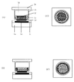
図1は本発明の電気泳動表示素子の一実施態様を示す構成図である。図1(A)は電気泳動表示素子の断面図であり、図1(B)はマイクロカプセルの配列を模式的に示した上図面である。
【0016】
図1(A)において、本発明の電気泳動表示素子は、第1基板1a上に第1電極1c、第2電極1dが形成されており、第2電極1d上にマイクロカプセル1hが配置され、第1基板1aと第2基板1bで挟まれた構成となっている。尚、第2電極1dは或る一定サイズを有する円形であって、図3(A)に示すようにハニカム状に配列している。電極間には絶縁層1iが形成されており、第1基板1aと第2基板1bは、接着剤1jで封止されている。
【0017】
マイクロカプセル1hの形状は、第1基板1aに対して水平方向の長さが垂直方向の長さよりも長い形状になっている。マイクロカプセル1hは、色と極性の異なる電気泳動粒子1e,1f及び分散媒1gから成る分散液を内包している。この電気泳動表示素子は、第2基板1bのある側が表示面である。又、マイクロカプセル1hは、図1(B)に示すような2次元配列で、第2電極1d上に配置されている。図1(B)においては、第2基板1bは省略されている。
【0018】
図1において、第2電極1dは個々のマイクロカプセル1hに対して、各々独立して所望の電界を印加できる画素電極であり、この画素電極にはスイッチ素子が設けられており、不図示のマトリクス駆動回路から行ごとに選択信号が印加され、更に各列に制御信号と駆動トランジスタからの出力が印加されて、個々のマイクロカプセル1hに対して所望の電界を印加することができる。
【0019】
個々のマイクロカプセル1h内の電気泳動粒子1e,1fは、第2電極1dにより印加される電界によって制御され、各画素は2種類の電気泳動粒子を制御して白黒の2色を表示する。第1電極1cは、全面同一電位で印加する共通電極である。
【0020】
次に、本発明の電気泳動表示素子の表示について図2を用いて説明する。尚、図2(A),(B)は電気泳動表示素子の断面図であり、図2(A’)、(B’)は上図面である。
【0021】
マイクロカプセル1hは色と極性の異なる電気泳動粒子1e,1f及び分散媒1gから成る分散液を内包している。電気泳動粒子1eは正に帯電した白色粒子であり、電気泳動粒子1fは負に帯電した黒色粒子である。分散媒1gは無色透明の絶縁性溶媒である。
【0022】
第1電極1cを0V、第2電極1dをプラスの電圧を印加すると、マイクロカプセル1h内の電気泳動粒子1eは第1電極1c上に集まり、電気泳動粒子1fは第2電極1d上に集まる。その結果、マイクロカプセル1hを上から観察すると黒色に見える。(図2(A)、(A’)参照)一方、第1電極1cを0V、第2電極1dをマイナスの電圧を印加した場合、マイクロカプセル1h内の電気泳動粒子1eは第2電極1dに集まり、電気泳動粒子1fは第1電極1cに集まるので、マイクロカプセル1hを上から観察すると白色に見える(図2(B),(B’)参照)。このようにして、白黒表示を行うことができる。
【0023】
次に、本発明に係る電気泳動表示粒子実施態様の製造方法を図3を用いて説明する。尚、図3は本発明の電気泳動表示素子の製造方法を示す工程図である。
【0024】
第1基板1a上に共通電極として第1電極1cを形成し、更に絶縁層1iを形成する。続いて、分散液を制御するための第2電極1dを、所望の直径を有する円形でもってハニカム状にパターン形成する(図3(A)参照)。
【0025】
第1基板1aは、電気泳動表示素子を支持する任意の絶縁部材であり、ガラスやプラスチック等を用いることができる。
【0026】
第1電極1cの材料は特に限定されないが、例えば、ITO(Indium Tin Oxide)、アルミニウム、チタン、有機導電性膜等を使用することができる。
【0027】
絶縁層1iは、絶縁性樹脂であれば特に限定されないが、例えば、アクリル樹脂、エポキシ樹脂、フッ素樹脂、シリコーン樹脂、ポリイミド樹脂、ポリスチレン樹脂、ポリアルケン樹脂等を使用することができる。
【0028】
第2電極1dのパターン形成にはフォトリソグラフィー法を用い、AlやITO等を使用することができる。第2電極1dの形状は円形であり、その直径はマイクロカプセル1hの直径の50%以上95%以下であり、好ましくは60%以上90%以下である。第2電極1dの直径がマイクロカプセル1hの直径の50%以下及び95%以上の場合、表示コントラストの低下を引き起し、好ましくない。
【0029】
第1基板1aに設けた第2電極1d上に、電気泳動粒子1e,1f及び分散媒1gから成る分散液を内包したマイクロカプセル1hを配置する(図3(B)参照)。
【0030】
マイクロカプセル1hを配置する方法は特に制限されないが、インクジェット方式のノズルや静電転写法等を使用することができる。
【0031】
前記分散液を内包するマイクロカプセル1hは、界面重合法、in situ 重合法、コアセルベーション法等の既知の方法で得ることができ、マイクロカプセル1hの直径は10〜500μm、好ましくは20〜200μmである。マイクロカプセル1hの直径が10μmよりも小さい場合、表示コントラストが低くなり好ましくない。
【0032】
一方、マイクロカプセル1hの直径が500μmよりも大きくなると、マイクロカプセル1hの膜強度が弱くなり実用的ではない。マイクロカプセル1hを形成する材料には光を十分に透過させる材料が好ましく、具体的には、尿素−ホルムアルデヒド樹脂、メラミン−ホルムアルデヒド樹脂 、ポリエステル、ポリウレタン、ポリアミド、ポリエチレン、ポリスチレン、ポリビニルアルコール、ゼラチン又はこれらの共重合体等を挙げることができる。
【0033】
電気泳動粒子1e,1fは、分散媒1g中で電界により移動可能な有機顔料粒子や無機顔料粒子等を使用することができる。電気泳動粒子1eは、例えば、酸化チタン、酸化アルミニウム、酸化亜鉛、酸化鉛、酸化スズ等の白色粒子を用いることができる。
【0034】
一方、電気泳動粒子1fは、例えば、カーボンブラック、ダイアモンドブラック、アニリンブラック、マンガンフェライトブラック、コバルトフェライトブラック、チタンブラック等の黒色粒子を用いることができる。
【0035】
又、粒子の表面を公知の電荷制御樹脂(CCR)で被覆することによって、電気泳動粒子1e,1fとして用いても良い。尚、電気泳動粒子1e,1fの大きさとしては、粒径が0. 05〜10μmのものが好ましく用いられ、更に好ましくは、0. 1〜6μmである。又、電気泳動粒子1e,1fの濃度は、1〜30重量%が好ましい。
【0036】
分散媒1gとしては、高絶縁性でしかも無色透明な液体が挙げられるが、例えば、トルエン、キシレン、エチルベンゼン、ドデシルベンゼン等の芳香族炭化水素、ヘキサン、シクロヘキサン、ケロシン、ノルマルパラフィン、イソパラフィンなどの脂肪族炭化水素、クロロホルム、ジクロロメタン、ペンタクロロエタン、1、2−ジブロモエタン、1、1、2、2−テトラブロモエタン、トリクロロエチレン、テトラクロロエチレン、トリフルオロエチレン、テトラフルオロエチレン等のハロゲン化炭化水素、天然又は合成の各種の油等を使用でき、これらを2種以上で混合して用いても良い。
【0037】
又、分散媒1gには、必要に応じて、電荷調整剤、分散剤、潤滑剤、安定化剤等を添加することができる。
【0038】
尚、基板上に配置されたマイクロカプセル1hの位置ずれを防止する目的で、マイクロカプセル1hの隙間に光透過性の樹脂バインダーを含浸させて基板上に固定しても良い。光透過性の樹脂バインダーとして、水溶性のポリマーを挙げることができ、例えば、ポリビニルアルコール、ポリウレタン、ポリエステル、アクリル樹脂、シリコーン樹脂等を用いることができる。
【0039】
電気泳動粒子1e,1f及び分散媒1gから成る分散液を内包したマイクロカプセル1hを第2電極1d上に配置した後、第2基板1bで覆い、第1基板1aと第2基板1bを接着剤1jを用いて封止する(図3(C)参照)。
【0040】
第1基板1aと第2基板1bを、接着剤1jを用いて封止する場合、マイクロカプセル1hの形状が、第1基板1aに対して水平方向の長さが垂直方向の長さよりも長い形状をとるように、押圧下で基板間を封止することが好ましい。
【0041】
第2基板1bとしては、第1基板1aと同様の材料を使用することができ、無色透明であることが好ましい。接着剤1jとしては、長期間接着効果が得られるものであれば、特に限定されるものではないが、例えば、エポキシ系樹脂、アクリル系樹脂、ウレタン系樹脂、酢酸ビニル系樹脂、フェノール系樹脂、ポリエステル系樹脂、ポリブタジエン系樹脂、シリコーン系樹脂等を1種単独又は2種以上の組合せで使用することができる。
【0042】
次に、本発明の電気泳動表示素子の他の実施態様例を示す。
【0043】
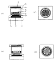
図4は本発明の電気泳動表示素子の他の実施態様例を示す構成図である。図4(A)は電気泳動表示素子の断面図であり、図4(B)は上図面である。
【0044】
図4(A)において、本発明の電気泳動表示素子は、第1基板2a上に第1電極2c、第2電極2dが形成されており、第2電極2d上にマイクロカプセル2hが配置され、第1基板2aと第2基板2bで挟まれた構成となっている。尚、第2電極2dは或る一定サイズを有する円形であって、図6(A)に示すようにハニカム状に配列している。電極間には絶縁層2iが形成されており、第1基板2aと第2基板2bは、接着剤2jで封止されている。
【0045】
マイクロカプセル2hの形状は、第1基板2aに対して水平方向の長さが垂直方向の長さよりも長い形状になっている。マイクロカプセル2hは、色と極性の異なる電気泳動粒子2e,2f及び分散媒2gから成る分散液を内包している。この電気泳動表示素子は、第2基板2bのある側が表示面である。又、カラーフィルター2kは、図4(B)に示すような2次元配列で第2基板2b上に設けられており、マイクロカプセル2hに対して1対1で対応するような構成になっている。
【0046】
図4において、第2電極2dは個々のマイクロカプセル2hに対して、各々独立して所望の電界を印加できる画素電極であり、この画素電極にはスイッチ素子が設けられており、不図示のマトリクス駆動回路から行ごとに選択信号が印加され、更に各列に制御信号と駆動トランジスタからの出力が印加されて、個々のマイクロカプセル2hに対して所望の電界を印加することができる。個々のマイクロカプセル2h内の電気泳動粒子2e,2fは、第2電極2dにより印加される電界によって制御され、各画素は2種類の電気泳動粒子を制御してカラー表示を行うことができる。第1電極2cは、全面同一電位で印加する共通電極である。
【0047】
次に、本発明の電気泳動表示素子の表示について図5を用いて説明する。
【0048】
図5(A),(B)は電気泳動表示素子の断面図であり、図5(A’)、(B’)は上図面であり、カラーフィルター2kを設けた第2基板2bは省略されている。マイクロカプセル2hは色と極性の異なる電気泳動粒子2e,2f及び分散媒2gから成る分散液を内包している。電気泳動粒子2eは正に帯電した白色粒子であり、電気泳動粒子2fは負に帯電した黒色粒子である。分散媒2gは無色透明の絶縁性溶媒である。第2基板2b上に設けられたカラーフィルターはR(レッド)である。
【0049】
第1電極2cを0V、第2電極2dをプラスの電圧を印加すると、マイクロカプセル2h内の電気泳動粒子2eは第1電極2c上に集まり、電気泳動粒子2fは第2電極2d上に集まる。その結果、マイクロカプセル2hを上から観察すると黒色に見える(図5(A)、(A’)参照)。
【0050】
一方、第1電極2cを0V、第2電極2dをマイナスの電圧を印加した場合、マイクロカプセル2h内の電気泳動粒子2eは第2電極2d上に集まり、電気泳動粒子2fは第1電極2c上に集まるので、マイクロカプセル2hを上から観察すると赤色に見える(図2(B)、(B’)参照)。
【0051】
カラーフィルター2kがG(グレーン)、B(ブルー)の場合、それぞれ黒−緑、黒−青の2値表示を行うことができ、カラーフィルター2kが図4(B)に示すような配列で第2基板2bに設けられた場合、電気泳動粒子2e,2fの電気泳動によってカラー表示を行うことができる。ここでは、カラーフィルター2kは、R,G,Bの3原色でカラー表示の一例を示したが、他の3原色であるY(イエロー)、M(マゼンタ)、C(シアン)のカラーフィルターを用いてカラー表示を行っても良い。
【0052】
次に、本発明に係る製造方法を図6を用いて説明する。図6は本発明の電気泳動表示素子の製造方法を示す工程図である。
【0053】
第1基板2a上に共通電極として第1電極2cを形成し、更に絶縁層2iを形成する。続いて、分散液を制御するための第2電極2dを所望の直径を有する円形でもってハニカム状にパターン形成する(図6(A)参照)。
【0054】
第1基板2aは、電気泳動表示素子を支持する任意の絶縁部材であり、前述したようにガラスやプラスチック等を用いることができる。
【0055】
第1電極2cの材料は特に限定されないが、前述したような材料を使用することができる。絶縁層2iの材料は特に限定されないが、前述したような絶縁性樹脂等を使用することができる。
【0056】
第2電極2dのパターン形成にはフォトリソグラフィー法を用い、前述したようにAlやITO等を使用することができる。第2電極2dの形状は円形であり、その直径はマイクロカプセル2hの直径の50%以上95%以下であり、好ましくは60%以上90%以下である。第2電極2dの直径がマイクロカプセル2hの直径の50%以下及び95%以上の場合、表示コントラストの低下を引起し、好ましくない。
【0057】
第1基板2aに設けた第2電極2d上に、電気泳動粒子2e,2f及び分散媒2gから成る分散液を内包したマイクロカプセル2hを配置する(図6(B)参照)。
【0058】
マイクロカプセル2hを配置する方法は特に制限されないが、インクジェット方式のノズルや静電転写法等を使用することができる。
【0059】
前記分散液を内包するマイクロカプセル2hは、前述したように、界面重合法、in situ 重合法、コアセルベーション法等の既知の方法で得ることができ、マイクロカプセル2hの直径は10〜500μm、好ましくは20〜200μmである。マイクロカプセル2hの直径が10μmよりも小さい場合、表示コントラストが低くなり好ましくない。一方、マイクロカプセル2hの直径が500μmよりも大きくなると、マイクロカプセル2hの膜強度が弱くなり実用的ではない。マイクロカプセル2hの形成材料には、前記した同様のポリマー材料を使用することができる。
【0060】
電気泳動粒子2e,2fと分散媒2gに関しては、前述した同様の粒子や分散媒を使用することができる。
【0061】
又、分散媒2gには、必要に応じて、電荷調整剤、分散剤、潤滑剤、安定化剤等を添加することができる。
【0062】
尚、基板上に配置されたマイクロカプセル2hの位置ずれを防止する目的で、マイクロカプセル2hの隙間に光透過性の樹脂バインダーを含浸させて基板上に固定しても良い。光透過性の樹脂バインダーとして、前述したような水溶性ポリマーを挙げることができる。
【0063】
電気泳動粒子2e,2f及び分散媒2gから成る分散液を内包したマイクロカプセル2hを第2電極2d上に配置した後、カラーフィルター2kを設けた第2基板2bで覆い、第1基板2aと第2基板2bを接着剤2jを用いて封止する(図6(C)参照)。
【0064】
第1基板2aと第2基板2bを接着剤2jを用いて封止する場合、マイクロカプセル2hの形状が第1基板2aに対して水平方向の長さが垂直方向の長さよりも長い形状をとるように、押圧下で基板間を封止することが好ましい。
【0065】
第2基板2bとしては、第1基板2aと同様の材料を使用することができ、無色透明であることが好ましい。接着剤2jには、前述した接着剤を使用することができる。
【0066】
以下に本発明の実施例を添付図面に基づいて説明する。
【0067】
<実施の形態1>
図1に示す電気泳動表示素子を図3の製造工程に従って作製した。
【0068】
PETフィルム(300μm厚)から成る第1基板1a上に第1電極1cとして、アルミニウム(0.2μm厚)を形成した。次に、絶縁層1iとしてアクリル系樹脂(2μm厚)を第1電極2c上に形成した。この絶縁層1i上に第2電極1dとしてアルミニウム(0.1μm厚)を成膜し、フォトリソグラフィー法によって直径40μmの円形でもってハニカム状にパターン形成した。尚、電極間距離(隣接する電極の中心間距離)は60μmで形成した。
【0069】
分散媒1gにはアイソパーH(エクソン化学)を使用した。電気泳動粒子1eには白色粒子(酸化チタン、平均粒径0.2μm)9重量%、電気泳動粒子1fには黒色粒子(カーボンをスチレン−ジビニルベンゼン樹脂で被覆した粒子、平均粒径0.5μm)8重量%及び帯電剤としてオロア(Chevron化学)0.5重量%を分散媒1gに加えて分散液を調整した。
【0070】
前記分散液を内包するマイクロカプセル1hをin situ 重合法により作製し、分級操作を行って粒径55〜60μmのマイクロカプセル1hを得た。膜材質は尿素−ホルムアルデヒド樹脂である。
【0071】
次に、インクジェット方式のノズルを用いて、マイクロカプセル1hを第2電極1d上に配置した。基板上に配置されたマイクロカプセル1hの位置ずれを防止する目的で、マイクロカプセル1hの隙間に光透過性の樹脂バインダーを含浸させて基板上に固定した。光透過性の樹脂バインダーとして、ポリビニルアルコールを用いた。
【0072】
次に、マイクロカプセル1hの上面を第2基板1bで覆い、マイクロカプセル1hの形状が、第1基板1aに対して水平方向の長さが垂直方向の長さよりも長い形状をとるように、接着剤1jを用いて押圧下で基板間を封止した。第2基板1bには無色透明なPETフィルム(100μm厚)を用いた。又、接着剤1jには、ポリエステル系樹脂を用いた。第1電極1c、第2電極1dに電圧印加回路を接続して表示素子を得た。
【0073】
表示は電極間に電圧を印加することによって行った。印加電圧・15Vで駆動したところ、図2に示すように各画素内の2種類の電気泳動粒子1e,1fの水平駆動によって白黒の高精細な表示を行うことができ、電気泳動粒子の搬送及び分散液の漏洩を防止することができた。
【0074】
<実施例2>
図4に示す電気泳動表示素子を図6の製造工程に従って作製した。
【0075】
実施例1と同様にして第1基板2a上に第1電極2c、絶縁層2i、第2電極2dを設けた。実施例1と同様に作製したマイクロカプセル2hをインクジェット方式のノズルを用いて第2電極2d上に配置した。基板上に配置されたマイクロカプセル2hの位置ずれを防止する目的で、マイクロカプセル2hの隙間に光透過性の樹脂バインダーを含浸させて基板上に固定した。光透過性の樹脂バインダーとして、ポリウレタンを用いた。
【0076】
次に、マイクロカプセル2hの層上をR,G,Bのカラーフィルター2kをパターン形成した厚さ100μmのPETフィルムで覆い、マイクロカプセル2hの形状が、第1基板2aに対して水平方向の長さが垂直方向の長さよりも長い形状をとるように、接着剤2jを用いて押圧下で基板間を封止した。接着剤2jには、ポリエステル系樹脂を用いた。第1電極2c,第2電極2dに電圧印加回路を接続して表示素子を得た。
【0077】
表示は電極間に電圧を印加することによって行った。印加電圧・15Vで駆動したところ、図5に示すように各画素内の2種類の電気泳動粒子2e,2fの水平駆動によって高精細なカラー表示を行うことができ、電気泳動粒子の搬送及び分散液の漏洩を防止することができた。
【0078】
【発明の効果】
以上の説明で明らかなように、本発明によれば、従来の電気泳動表示素子において課題であった電気泳動粒子の搬送及び分散液の漏洩に対して分散液のマイクロカプセル化によって課題を解決した電気泳動表示素子を提供することができる。
【図面の簡単な説明】
【図1】(A)は本発明の電気泳動表示素子の一実施態様を示す断面図であり、(B)は上図面ある。
【図2】本発明の電気泳動表示素子におけるマイクロカプセルの表示方法を示す概略図である。
【図3】本発明の電気泳動表示素子の製造方法の一例を示す工程図である。
【図4】(A)は本発明の電気泳動表示素子の一実施態様を示す断面図、(B)は上図面ある。
【図5】本発明の電気泳動表示素子におけるマイクロカプセルの表示方法を示す概略図である。
【図6】本発明の電気泳動表示素子の製造方法の一例を示す工程図である。
【図7】従来の電気泳動型表示素子を示す概略図である。
【符号の説明】
1a 第1基板
1b 第2基板
1c 第1電極
1d 第2電極
1e 電気泳動粒子
1f 電気泳動粒子
1g 分散媒
1h マイクロカプセル
1i 絶縁層
1j 接着剤
2a 第1基板
2b 第2基板
2c 第1電極
2d 第2電極
2e 電気泳動粒子
2f 電気泳動粒子
2g 分散媒
2h マイクロカプセル
2i 絶縁層
2j 接着剤
2k カラーフィルター
3a 基板
3b 基板
3c 電極
3d 電極
3e 電気泳動粒子
3f 分散媒
3g 隔壁[0001]
TECHNICAL FIELD OF THE INVENTION
The present invention relates to an electrophoretic display device and a method for manufacturing the same.
[0002]
[Prior art]
In recent years, with the development of information equipment, needs for low power consumption and thin display elements have been increasing, and research and development of display elements that meet these needs have been actively conducted. Among them, a liquid crystal display element has been actively developed and commercialized as a display element capable of changing the optical characteristics of liquid crystal by electrically controlling the arrangement of liquid crystal molecules and meeting the above needs.
[0003]
However, these liquid crystal display elements have sufficiently solved the problem that characters on the screen are difficult to see due to the angle and reflected light when viewing the screen, or the burden on the visual field caused by flickering of the light source and low brightness. Absent. For this reason, research on a display element with a small burden on vision has been actively studied.
[0004]
As one of such display elements, Harold D.S. An electrophoretic display device invented by Lees et al. (US Pat. No. 3,612,758) is known. FIG. 7 is a schematic diagram showing the structure of the electrophoretic display element and the operation principle thereof.
[0005]
In FIG. 7, the electrophoretic display device includes a pair of substrates 3a and 3b arranged with a predetermined gap therebetween, and electrodes 3c and 3d are formed on each of the substrates. The gap between the substrates is filled with a large number of positively charged and colored electrophoretic particles 3e and a dispersion medium 3f colored with a different color from the electrophoretic particles. Further, the partition walls 3g are arranged so as to divide the gap into a number of pixels along the surface direction of the substrate, so as to prevent uneven distribution of the electrophoretic particles and to define the substrate gap.
[0006]
In such a display element, when a negative voltage is applied to the lower electrode 3c and a positive voltage is applied to the upper electrode 3d as shown in FIG. The electrophoretic particles 3e gather so as to cover the lower electrode 3c, and when the display element is viewed from the direction C in the drawing, the same color as the dispersion medium 3f is displayed. Conversely, as shown in FIG. 7B, when a positive voltage is applied to the lower electrode 3c in the figure and a negative voltage is applied to the upper electrode 3d in the figure, the electrophoretic particles 3e are turned into the upper electrode 3d. When the display element is viewed from the direction C in the drawing, the same color as the electrophoretic particles 3e is displayed. By performing such driving in units of pixels, an arbitrary image is displayed by a large number of pixels.
[0007]
[Problems to be solved by the invention]
In the conventional electrophoretic display element, there is a problem that the electrophoretic particles pass over the partition and are conveyed to an adjacent pixel. Further, there is a problem that the dispersion liquid leaks out of the display element.
[0008]
The present invention has been made in view of the above problems, and an object of the present invention is to provide an electrophoretic display element in which transport of electrophoretic particles and leakage of a dispersion liquid are solved, and a method for manufacturing the same.
[0009]
[Means for Solving the Problems]
In order to achieve the above object, the present invention disposes microcapsules containing two types of electrophoretic particles having different polarities and colors and a dispersion medium at desired positions on a substrate provided with a first electrode and a second electrode. Performing the display by moving the two types of electrophoretic particles in any direction of the first electrode and the second electrode by the voltage applied to the first electrode and the second electrode. This is a characteristic electrophoretic display element.
[0010]
According to the present invention, there is provided an electrophoretic display element wherein the two types of electrophoretic particles are white and black, respectively, and display black and white.
[0011]
Further, the present invention is characterized in that color display is performed by disposing a color filter on the microcapsule.
[0012]
Further, according to the present invention, microcapsules containing a dispersion liquid comprising two types of electrophoretic particles having different polarities and colors and a dispersion medium are arranged at desired positions on a substrate provided with a first electrode and a second electrode. A method for manufacturing an electrophoretic display element,
(1) forming a first electrode and a second electrode on a plate;
(2) a step of disposing a microcapsule containing a dispersion liquid composed of two kinds of electrophoretic particles having different polarities and colors and a dispersion medium at a desired position on the substrate;
(3) a step of covering the microcapsules with an opposing substrate and sealing between the substrates;
And a method for manufacturing an electrophoretic display element.
[0013]
Further, the present invention provides a microcapsule and a color filter in which a dispersion liquid comprising two kinds of electrophoretic particles having different polarities and colors and a dispersion medium are contained at desired positions on a substrate provided with a first electrode and a second electrode. A method for manufacturing an electrophoretic display element in which
(1) forming a first electrode and a second electrode on a substrate;
(2) a step of disposing a microcapsule containing a dispersion liquid composed of two kinds of electrophoretic particles having different polarities and colors and a dispersion medium at a desired position on the substrate;
(3) a step of covering the microcapsules with a substrate provided with a color filter and sealing between the substrates;
And a method for manufacturing an electrophoretic display element.
[0014]
BEST MODE FOR CARRYING OUT THE INVENTION
Hereinafter, embodiments of the present invention will be described with reference to the accompanying drawings.
[0015]
FIG. 1 is a configuration diagram showing one embodiment of the electrophoretic display element of the present invention. FIG. 1A is a cross-sectional view of an electrophoretic display element, and FIG. 1B is a top view schematically showing an arrangement of microcapsules.
[0016]
In FIG. 1A, the electrophoretic display device of the present invention has a first electrode 1c and a second electrode 1d formed on a first substrate 1a, and a microcapsule 1h disposed on the second electrode 1d. It has a configuration sandwiched between a first substrate 1a and a second substrate 1b. The second electrode 1d is a circle having a certain size, and is arranged in a honeycomb shape as shown in FIG. An insulating layer 1i is formed between the electrodes, and the first substrate 1a and the second substrate 1b are sealed with an adhesive 1j.
[0017]
The shape of the microcapsule 1h is such that the length in the horizontal direction with respect to the first substrate 1a is longer than the length in the vertical direction. The microcapsule 1h contains a dispersion liquid composed of electrophoretic particles 1e and 1f having different colors and polarities and a
[0018]
In FIG. 1, a second electrode 1d is a pixel electrode capable of independently applying a desired electric field to each microcapsule 1h. The pixel electrode is provided with a switch element, and a matrix (not shown). A selection signal is applied from the drive circuit for each row, and a control signal and an output from the drive transistor are applied to each column, so that a desired electric field can be applied to each microcapsule 1h.
[0019]
The electrophoretic particles 1e and 1f in each microcapsule 1h are controlled by an electric field applied by the second electrode 1d, and each pixel controls two types of electrophoretic particles to display two colors of black and white. The first electrode 1c is a common electrode applied at the same potential over the entire surface.
[0020]
Next, display of the electrophoretic display element of the present invention will be described with reference to FIG. 2A and 2B are cross-sectional views of the electrophoretic display element, and FIGS. 2A and 2B are upper drawings.
[0021]
The microcapsule 1h contains a dispersion liquid composed of electrophoretic particles 1e and 1f having different colors and polarities and a
[0022]
When 0V is applied to the first electrode 1c and a positive voltage is applied to the second electrode 1d, the electrophoretic particles 1e in the microcapsule 1h collect on the first electrode 1c, and the electrophoretic particles 1f collect on the second electrode 1d. As a result, when the microcapsules 1h are observed from above, they appear black. (See FIGS. 2A and 2A.) On the other hand, when 0V is applied to the first electrode 1c and a negative voltage is applied to the second electrode 1d, the electrophoretic particles 1e in the microcapsule 1h are applied to the second electrode 1d. Since the collected electrophoretic particles 1f are collected on the first electrode 1c, the microcapsules 1h appear white when viewed from above (see FIGS. 2B and 2B). In this way, monochrome display can be performed.
[0023]
Next, a method for manufacturing an embodiment of the electrophoretic display particles according to the present invention will be described with reference to FIG. FIG. 3 is a process chart showing a method for manufacturing an electrophoretic display device of the present invention.
[0024]
A first electrode 1c is formed as a common electrode on a first substrate 1a, and an insulating layer 1i is further formed. Subsequently, the second electrode 1d for controlling the dispersion liquid is patterned in a honeycomb shape with a circle having a desired diameter (see FIG. 3A).
[0025]
The first substrate 1a is an arbitrary insulating member that supports the electrophoretic display element, and may be made of glass, plastic, or the like.
[0026]
Although the material of the first electrode 1c is not particularly limited, for example, ITO (Indium Tin Oxide), aluminum, titanium, an organic conductive film, or the like can be used.
[0027]
The insulating layer 1i is not particularly limited as long as it is an insulating resin. For example, an acrylic resin, an epoxy resin, a fluororesin, a silicone resin, a polyimide resin, a polystyrene resin, a polyalkene resin, or the like can be used.
[0028]
Photolithography is used to form the pattern of the second electrode 1d, and Al or ITO can be used. The shape of the second electrode 1d is circular, and the diameter thereof is 50% or more and 95% or less, preferably 60% or more and 90% or less of the diameter of the microcapsule 1h. When the diameter of the second electrode 1d is 50% or less and 95% or more of the diameter of the microcapsule 1h, the display contrast is lowered, which is not preferable.
[0029]
A microcapsule 1h containing a dispersion liquid composed of electrophoretic particles 1e and 1f and a
[0030]
The method for arranging the microcapsules 1h is not particularly limited, but an inkjet nozzle, an electrostatic transfer method, or the like can be used.
[0031]
The microcapsules 1h enclosing the dispersion can be obtained by a known method such as an interfacial polymerization method, an in situ polymerization method, a coacervation method, and the diameter of the microcapsules 1h is 10 to 500 µm, preferably 20 to 200 µm. It is. If the diameter of the microcapsule 1h is smaller than 10 μm, the display contrast is undesirably low.
[0032]
On the other hand, when the diameter of the microcapsule 1h is larger than 500 μm, the film strength of the microcapsule 1h becomes weak, which is not practical. The material forming the microcapsules 1h is preferably a material that sufficiently transmits light, specifically, urea-formaldehyde resin, melamine-formaldehyde resin, polyester, polyurethane, polyamide, polyethylene, polystyrene, polyvinyl alcohol, gelatin, or these. And the like.
[0033]
As the electrophoretic particles 1e and 1f, organic pigment particles, inorganic pigment particles, or the like that can move by an electric field in 1 g of a dispersion medium can be used. As the electrophoretic particles 1e, for example, white particles such as titanium oxide, aluminum oxide, zinc oxide, lead oxide, and tin oxide can be used.
[0034]
On the other hand, as the electrophoretic particles 1f, for example, black particles such as carbon black, diamond black, aniline black, manganese ferrite black, cobalt ferrite black, and titanium black can be used.
[0035]
The electrophoretic particles 1e and 1f may be used by coating the surface of the particles with a known charge control resin (CCR). In addition, as for the size of the electrophoretic particles 1e and 1f, the particle size is set to 0. Those having a thickness of from 0.05 to 10 μm are preferably used, and more preferably from 0. 1 to 6 μm. The concentration of the electrophoretic particles 1e, 1f is preferably 1 to 30% by weight.
[0036]
Examples of 1 g of the dispersion medium include highly insulative and colorless and transparent liquids such as aromatic hydrocarbons such as toluene, xylene, ethylbenzene and dodecylbenzene, and fats such as hexane, cyclohexane, kerosene, normal paraffin and isoparaffin. Aromatic hydrocarbons, chloroform, dichloromethane, pentachloroethane, 1,2-dibromoethane, 1,1,2,2-tetrabromoethane, trichloroethylene, tetrachloroethylene, trifluoroethylene, halogenated hydrocarbons such as tetrafluoroethylene, natural or Various synthetic oils and the like can be used, and these may be used as a mixture of two or more kinds.
[0037]
If necessary, a charge control agent, a dispersant, a lubricant, a stabilizer, and the like can be added to 1 g of the dispersion medium.
[0038]
In order to prevent the displacement of the microcapsules 1h arranged on the substrate, the gaps between the microcapsules 1h may be impregnated with a light-transmitting resin binder and fixed on the substrate. Examples of the light-transmitting resin binder include a water-soluble polymer, and examples thereof include polyvinyl alcohol, polyurethane, polyester, acrylic resin, and silicone resin.
[0039]
After disposing a microcapsule 1h containing a dispersion composed of electrophoretic particles 1e and 1f and a
[0040]
When the first substrate 1a and the second substrate 1b are sealed using the adhesive 1j, the shape of the microcapsule 1h is such that the horizontal length of the microcapsule 1h is longer than the vertical length of the first substrate 1a. It is preferable to seal the space between the substrates under pressure so as to take the following.
[0041]
The same material as that of the first substrate 1a can be used for the second substrate 1b, and it is preferable that the second substrate 1b be colorless and transparent. The adhesive 1j is not particularly limited as long as an adhesive effect can be obtained for a long period of time. For example, an epoxy resin, an acrylic resin, a urethane resin, a vinyl acetate resin, a phenol resin, Polyester resins, polybutadiene resins, silicone resins and the like can be used alone or in combination of two or more.
[0042]
Next, another embodiment of the electrophoretic display device of the present invention will be described.
[0043]
FIG. 4 is a configuration diagram showing another embodiment of the electrophoretic display element of the present invention. FIG. 4A is a cross-sectional view of the electrophoretic display device, and FIG. 4B is an upper drawing.
[0044]
In FIG. 4A, in the electrophoretic display device of the present invention, a
[0045]
The shape of the
[0046]
In FIG. 4, a
[0047]
Next, display of the electrophoretic display element of the present invention will be described with reference to FIG.
[0048]
FIGS. 5A and 5B are cross-sectional views of the electrophoretic display device, and FIGS. 5A and 5B are upper drawings, in which the second substrate 2b provided with the color filter 2k is omitted. ing. The
[0049]
When 0V is applied to the
[0050]
On the other hand, when 0V is applied to the
[0051]
When the color filters 2k are G (grain) and B (blue), binary display of black-green and black-blue can be performed, respectively, and the color filters 2k are arranged in an array as shown in FIG. When provided on the two substrates 2b, color display can be performed by electrophoresis of the electrophoretic particles 2e and 2f. Here, the color filter 2k shows an example of color display using the three primary colors of R, G, and B. However, the color filters of the other three primary colors, Y (yellow), M (magenta), and C (cyan), are used. Color display may be performed by using the above.
[0052]
Next, a manufacturing method according to the present invention will be described with reference to FIG. FIG. 6 is a process chart showing a method for manufacturing an electrophoretic display element of the present invention.
[0053]
A
[0054]
The first substrate 2a is an arbitrary insulating member that supports the electrophoretic display element, and can use glass, plastic, or the like as described above.
[0055]
The material of the
[0056]
Photolithography is used to form the pattern of the
[0057]
On a
[0058]
The method for arranging the
[0059]
As described above, the
[0060]
As for the electrophoretic particles 2e and 2f and the dispersion medium 2g, the same particles and dispersion medium as described above can be used.
[0061]
If necessary, a charge control agent, a dispersant, a lubricant, a stabilizer, and the like can be added to 2 g of the dispersion medium.
[0062]
In order to prevent the displacement of the
[0063]
After disposing a
[0064]
When the first substrate 2a and the second substrate 2b are sealed with the adhesive 2j, the shape of the
[0065]
As the second substrate 2b, the same material as that of the first substrate 2a can be used, and it is preferable that the second substrate 2b be colorless and transparent. The above-mentioned adhesive can be used as the adhesive 2j.
[0066]
Hereinafter, embodiments of the present invention will be described with reference to the accompanying drawings.
[0067]
<Embodiment 1>
The electrophoretic display device shown in FIG. 1 was manufactured according to the manufacturing process shown in FIG.
[0068]
Aluminum (0.2 μm thick) was formed as a first electrode 1 c on a first substrate 1 a made of a PET film (300 μm thick). Next, an acrylic resin (2 μm thick) was formed on the
[0069]
Isopar H (Exxon Chemical) was used for 1 g of the dispersion medium. 9% by weight of white particles (titanium oxide, average particle size 0.2 μm) for the electrophoretic particles 1e, and black particles (particles of carbon coated with styrene-divinylbenzene resin, average particle size of 0.5 μm) for the electrophoretic particles 1f. ) 8% by weight and 0.5% by weight of Oroa (Chevron Chemical Co.) as a charging agent were added to 1 g of a dispersion medium to prepare a dispersion.
[0070]
Microcapsules 1h enclosing the dispersion were prepared by an in situ polymerization method, and classified to obtain microcapsules 1h having a particle size of 55 to 60 μm. The film material is urea-formaldehyde resin.
[0071]
Next, the microcapsules 1h were arranged on the second electrodes 1d by using an inkjet type nozzle. In order to prevent displacement of the microcapsules 1h arranged on the substrate, the gaps between the microcapsules 1h were impregnated with a light-transmitting resin binder and fixed on the substrate. Polyvinyl alcohol was used as a light-transmitting resin binder.
[0072]
Next, the upper surface of the microcapsule 1h is covered with the second substrate 1b, and the microcapsule 1h is bonded to the first substrate 1a such that the horizontal length is longer than the vertical length with respect to the first substrate 1a. The space between the substrates was sealed under pressure using the agent 1j. A colorless and transparent PET film (100 μm thick) was used for the second substrate 1b. A polyester resin was used for the adhesive 1j. A display element was obtained by connecting a voltage application circuit to the first electrode 1c and the second electrode 1d.
[0073]
The display was performed by applying a voltage between the electrodes. When driven at an applied voltage of 15 V, as shown in FIG. 2, two types of electrophoretic particles 1e and 1f in each pixel can be driven horizontally to perform black and white high-definition display. Leakage of the dispersion liquid could be prevented.
[0074]
<Example 2>
The electrophoretic display device shown in FIG. 4 was manufactured according to the manufacturing process of FIG.
[0075]
A
[0076]
Next, the layer of the
[0077]
The display was performed by applying a voltage between the electrodes. When driven by an applied voltage of 15 V, high-definition color display can be performed by horizontal driving of two types of electrophoretic particles 2e and 2f in each pixel as shown in FIG. The leakage of the liquid was prevented.
[0078]
【The invention's effect】
As is apparent from the above description, according to the present invention, the problem was solved by the microencapsulation of the dispersion against the transport of the electrophoretic particles and the leakage of the dispersion, which were problems in the conventional electrophoretic display element. An electrophoretic display device can be provided.
[Brief description of the drawings]
FIG. 1A is a cross-sectional view showing one embodiment of the electrophoretic display element of the present invention, and FIG. 1B is the upper drawing.
FIG. 2 is a schematic view showing a method for displaying microcapsules in the electrophoretic display device of the present invention.
FIG. 3 is a process chart showing an example of a method for manufacturing an electrophoretic display element of the present invention.
FIG. 4A is a cross-sectional view showing one embodiment of the electrophoretic display element of the present invention, and FIG.
FIG. 5 is a schematic view showing a method for displaying microcapsules in the electrophoretic display device of the present invention.
FIG. 6 is a process chart showing one example of a method for manufacturing an electrophoretic display element of the present invention.
FIG. 7 is a schematic view showing a conventional electrophoretic display device.
[Explanation of symbols]
1a First substrate 1b Second substrate 1c First electrode 1d Second electrode 1e Electrophoretic particles 1f
Claims (5)
(1)基板上に第1電極と第2電極を形成する工程、
(2)極性と色の異なる2種類の電気泳動粒子と分散媒から成る分散液を内包したマイクロカプセルを該基板上の所望の位置に配置する工程、
(3)マイクロカプセル上を対向する基板で覆い、基板間を封止する工程、
の各工程を有することを特徴とする電気泳動表示素子の製造方法。Manufacture of an electrophoretic display element in which microcapsules containing a dispersion liquid composed of two kinds of electrophoretic particles having different polarities and colors and a dispersion medium are arranged at desired positions on a substrate provided with a first electrode and a second electrode. The method,
(1) forming a first electrode and a second electrode on a substrate;
(2) a step of disposing a microcapsule containing a dispersion liquid composed of two kinds of electrophoretic particles having different polarities and colors and a dispersion medium at a desired position on the substrate;
(3) a step of covering the microcapsules with an opposing substrate and sealing between the substrates;
A method for manufacturing an electrophoretic display element, comprising the steps of:
(1)基板上に第1電極と第2電極を形成する工程、
(2)極性と色の異なる2種類の電気泳動粒子と分散媒から成る分散液を内包したマイクロカプセルを該基板上の所望の位置に配置する工程、
(3)マイクロカプセル上を、カラーフィルターを設けた基板で覆い、基板間を封止する工程、
の各工程を有することを特徴とする電気泳動表示素子の製造方法。Electrophoretic display in which microcapsules containing a dispersion liquid composed of two types of electrophoretic particles having different polarities and colors and a dispersion medium and a color filter are arranged at desired positions on a substrate provided with a first electrode and a second electrode. A method for manufacturing an element,
(1) forming a first electrode and a second electrode on a substrate;
(2) a step of disposing a microcapsule containing a dispersion liquid composed of two kinds of electrophoretic particles having different polarities and colors and a dispersion medium at a desired position on the substrate;
(3) a step of covering the microcapsules with a substrate provided with a color filter and sealing between the substrates;
A method for manufacturing an electrophoretic display element, comprising the steps of:
Priority Applications (2)
| Application Number | Priority Date | Filing Date | Title |
|---|---|---|---|
| JP2003024295A JP2004233838A (en) | 2003-01-31 | 2003-01-31 | Electrophoresis display element and method for manufacturing the same |
| US10/769,374 US20050012979A1 (en) | 2003-01-31 | 2004-01-30 | Electrophoretic Display |
Applications Claiming Priority (1)
| Application Number | Priority Date | Filing Date | Title |
|---|---|---|---|
| JP2003024295A JP2004233838A (en) | 2003-01-31 | 2003-01-31 | Electrophoresis display element and method for manufacturing the same |
Publications (1)
| Publication Number | Publication Date |
|---|---|
| JP2004233838A true JP2004233838A (en) | 2004-08-19 |
Family
ID=32952863
Family Applications (1)
| Application Number | Title | Priority Date | Filing Date |
|---|---|---|---|
| JP2003024295A Pending JP2004233838A (en) | 2003-01-31 | 2003-01-31 | Electrophoresis display element and method for manufacturing the same |
Country Status (2)
| Country | Link |
|---|---|
| US (1) | US20050012979A1 (en) |
| JP (1) | JP2004233838A (en) |
Cited By (1)
| Publication number | Priority date | Publication date | Assignee | Title |
|---|---|---|---|---|
| KR100741210B1 (en) * | 2006-01-11 | 2007-07-19 | 엘지전자 주식회사 | Microcapsule of Electrophoretic Electronic Paper and Electrophoretic Electronic Paper Display Device Having The Same |
Families Citing this family (9)
| Publication number | Priority date | Publication date | Assignee | Title |
|---|---|---|---|---|
| US7710389B2 (en) * | 2005-11-04 | 2010-05-04 | Xerox Corporation | Multi-layer display device using dot field applicators |
| KR101480003B1 (en) * | 2008-03-31 | 2015-01-09 | 삼성디스플레이 주식회사 | Method of driving electrophoretic display |
| KR101759643B1 (en) * | 2010-12-17 | 2017-08-01 | 삼성디스플레이 주식회사 | Electrophoresis display apparatus |
| US9835926B2 (en) * | 2012-03-21 | 2017-12-05 | E Ink California, Llc | Electrophoretic dispersion |
| US10288975B2 (en) * | 2012-03-21 | 2019-05-14 | E Ink California, Llc | Electrophoretic dispersion including charged pigment particles, uncharged additive nanoparticles, and uncharged neutral density particles |
| JP2013222090A (en) * | 2012-04-17 | 2013-10-28 | Seiko Epson Corp | Base material for electrophoretic display device and manufacturing method for the same, and electrophoretic display device and manufacturing method for the same |
| TWI519608B (en) * | 2013-12-27 | 2016-02-01 | 財團法人工業技術研究院 | Hybrid carbon black, coating composition and shielding material employing the same |
| TWI565655B (en) * | 2015-09-25 | 2017-01-11 | 財團法人工業技術研究院 | Hybrid carbon black and coating composition |
| JP7407293B2 (en) * | 2020-02-07 | 2023-12-28 | イー インク コーポレイション | Electrophoretic display layer with thin film top electrode |
Family Cites Families (6)
| Publication number | Priority date | Publication date | Assignee | Title |
|---|---|---|---|---|
| JP2001056653A (en) * | 1999-06-11 | 2001-02-27 | Ricoh Co Ltd | Display liquid for electrophoresis display, display particles, display medium utilizing the foregoing same, display device, display method, display, recording sheet, display and reversible display type signboard |
| KR100575452B1 (en) * | 1999-09-28 | 2006-05-03 | 엘지.필립스 엘시디 주식회사 | electroretic display and transflective liquid crystal display device using electroretic display |
| JP4155553B2 (en) * | 2001-08-01 | 2008-09-24 | キヤノン株式会社 | Display element and manufacturing method thereof |
| JP4007119B2 (en) * | 2001-08-23 | 2007-11-14 | セイコーエプソン株式会社 | Method for manufacturing electrophoresis apparatus |
| JP4027178B2 (en) * | 2001-09-12 | 2007-12-26 | キヤノン株式会社 | Electrophoretic display device |
| JP4427942B2 (en) * | 2002-08-29 | 2010-03-10 | 富士ゼロックス株式会社 | Image writing device |
-
2003
- 2003-01-31 JP JP2003024295A patent/JP2004233838A/en active Pending
-
2004
- 2004-01-30 US US10/769,374 patent/US20050012979A1/en not_active Abandoned
Cited By (1)
| Publication number | Priority date | Publication date | Assignee | Title |
|---|---|---|---|---|
| KR100741210B1 (en) * | 2006-01-11 | 2007-07-19 | 엘지전자 주식회사 | Microcapsule of Electrophoretic Electronic Paper and Electrophoretic Electronic Paper Display Device Having The Same |
Also Published As
| Publication number | Publication date |
|---|---|
| US20050012979A1 (en) | 2005-01-20 |
Similar Documents
| Publication | Publication Date | Title |
|---|---|---|
| US11733580B2 (en) | Method for driving two layer variable transmission display | |
| US8797634B2 (en) | Multi-color electrophoretic displays | |
| JP4783781B2 (en) | Backplane for electro-optic display | |
| JP4154175B2 (en) | Method for manufacturing electrophoretic display element | |
| JP2004020818A (en) | Collar electrophoretic display device | |
| JPH11202804A (en) | Electrophoresis display device | |
| JP2004233838A (en) | Electrophoresis display element and method for manufacturing the same | |
| JP4508322B2 (en) | Display device | |
| US7161731B2 (en) | Method of manufacturing electrophoretic display | |
| JP2000352728A (en) | Display device and production of the display device | |
| JP4416197B2 (en) | Electrophoretic display device | |
| CN114265256B (en) | Manufacturing method of electronic paper display equipment | |
| JP5299222B2 (en) | Image display medium, image display apparatus, and method of manufacturing image display medium | |
| JPH11219135A (en) | Electrophoresis display unit | |
| JP2001125150A (en) | Display device and method of producing the same | |
| JP2007240758A (en) | Image display medium, image display apparatus and image display method | |
| KR20230078791A (en) | Driving sequences for removing previous state information from color electrophoretic displays | |
| TWI578078B (en) | Multi-color electrophoretic displays | |
| JP2001125514A (en) | Display device and method of producing the same | |
| TWI489192B (en) | Multi-color electrophoretic displays | |
| KR101936682B1 (en) | Electrophoretic display device and driving method the same | |
| JP2004012829A (en) | Electrophoresis display device | |
| TW201719260A (en) | Multi-color electrophoretic displays |
Legal Events
| Date | Code | Title | Description |
|---|---|---|---|
| RD01 | Notification of change of attorney |
Free format text: JAPANESE INTERMEDIATE CODE: A7421 Effective date: 20060201 |
|
| A072 | Dismissal of procedure [no reply to invitation to correct request for examination] |
Free format text: JAPANESE INTERMEDIATE CODE: A072 Effective date: 20060606 |