【0001】
【発明の属する技術分野】
本発明は、携帯型電話や電子手帳などの液晶表示装置に使用されるバックライト装置に関するものである。
【0002】
【従来の技術】
本願出願人は、この種のバックライト装置として、特願2002―276442号を提案している。図4はバックライト装置4を備えた液晶表示装置1の断面構造を示したものであり、枠体2の上部に液晶表示パネル3を、その下部に前記のバックライト装置4を配置した構造である。このバックライト装置4は、光源であるLED5と、このLED5で発した光を液晶表示パネル3の裏面側に導くための導光板6と、この導光板6の上下面に配置された一対の拡散シート8,9と、前記下部拡散シート9の下面に配置された反射シート10とを備えた構造である。前記導光板6は、透明なアクリル板又はポロカーボネイト板によって形成されており、その一端にはLED5の上方にまで延びる受光部7を有している。この受光部7は上面が斜めにカットされた反射面7aを有すると共に、LED5と向かい合う受光部7の下面には平面状の受光面7bを有する形状である。なお、前記LED5は各種のICや電子部品が実装される回路基板11の先端部に実装されている。
【0003】
前記LED5から受光面7bに向かって放射された光は、受光面7bから受光部7に入射したのち、反射面7aによって前方側に反射され、そのまま導光板6内を進みながら、上方に配置された液晶表示パネル3を背面側から照射する。そして、導光板6内を光が進むときに前記導光板6の上下面に配置された拡散シート8,9及び下部拡散シート9の下面に配置された反射シート10によって光の拡散や反射が繰り返され、導光板全体の輝度が高められると共に輝度ムラが抑えられる。
【0004】
【発明が解決しようとする課題】
ところで、上述したバックライト装置4では、導光板6の上下に配置した拡散シート8,9や反射シート10によって、導光板6の輝度を高めると共に輝度ムラを抑える効果を持たせているが、導光板6の厚みがさらに薄くなってくると、導光板6の先端部分にまで届く光量が極めて少なくなってしまうために、特に先端部分で輝度低下が著しく、それが導光板全体の輝度ムラとなって現れるといった問題があった。
【0005】
そこで、本発明の目的は、薄型の導光板を使用した場合でも導光板の先端部分での輝度低下を防ぐことによって輝度ムラのないバックライトを実現することのできる液晶表示パネルのバックライト装置を提供するものである。
【0006】
【課題を解決するための手段】
上記課題を解決するために、本発明の請求項1に係る液晶表示パネルのバックライト装置は、光源と、この光源で発した光を導く導光板と、この導光板の上下面に配置された拡散シートと、前記下部拡散シートの下面に配置された反射シートとを備え、前記導光板によって液晶表示パネルを照射する液晶表示装置のバックライト装置において、前記拡散シート及び反射シートを導光板の先端部の端面にも配置したことを特徴とする。
【0007】
この発明によれば、導光板の先端部の端面に配置された拡散シート及び反射シートの作用によって、導光板の先端部分に届く光が僅かなものであっても、先端部分での輝度アップが図られることになり、導光板全体の輝度ムラが抑えられる。
【0008】
前記拡散シートは、導光板の先端部の端面を包み込むようにして上下面に配置されることから、これらを一枚のシートで形成することもできる。導光板の厚みが非常に薄いことから、導光板の先端部分に配置される拡散シートを導光板の上下面に配置される拡散シートと一体化することで、その取扱いが非常に簡便となる他、先端部の端面を確実に被覆することができる。
【0009】
【発明の実施の形態】
以下、添付図面に基づいて本発明に係る液晶表示パネルのバックライト装置を詳細に説明する。
【0010】
図1は、本発明に係るバックライト装置24を組み込んだ液晶表示装置21を示したものである。このバックライト装置24は、基本的には従来のバックライト装置1と同様、枠体22の上部に保持された液晶表示パネル23の下部に配設された構造である。即ち、光源であるLED25と、このLED25で発した光を液晶表示パネル23の裏面側に導くための導光板26と、この導光板26の上面及び下面に配置された拡散シート28,29と、下部拡散シート29の下面に配置された反射シート30とを備える。前記導光板26は、透明なアクリル板によって形成されており、その一端にはLED25の上方にまで延びる受光部27が形成される。そして、この受光部27は、斜めにカットされた上面の反射面227aと、LED25の発光面と向かい合う受光面27bとを有している。
【0011】
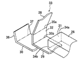
一方、この実施形態に係るバックライト装置24は、従来とは異なって、導光板26の先端部の端面31を覆うようにして拡散シートと反射シートが配置されている。この実施形態では、図2及び図3に示したように、導光板26の上面に配置される上部拡散シート28、導光板26の下面に配置される下部拡散シート29及び導光板26の端面31に配置される先端部拡散シート32が一枚の拡散シート部材33によって一体に形成されている。そして、この拡散シート部材33には導光板26の端面31の上下角部34a,34bに対応する部分に谷折れ側の筋目35a,35bが設けられている。したがって、導光板26の表面に拡散シート部材33を配置する場合には、端面31の上下角部34a,34bに筋目35a,35bを位置合わせしたのち、導光板26の上下面に沿って被せるだけで簡単に装着できる他、導光板26の薄い端面31にも隙間なくピッタリと装着されることになる。
【0012】
なお、上記の拡散シート部材33は、透明なポリエステルフィルムの表面に微細な凹凸部を設けたものであり、例えば大小様々なビーズをフィルム表面にコーティングすることで凹凸部が形成される。
【0013】
また、この実施形態に係るバックライト装置24では、導光板26の下面側に配置されていた反射シート30の先端部分を延ばし、その先端部反射シート36を導光板26の端面31側に起こして、先端部拡散シート32の外側面に接するように配置する。この場合にも導光板26の下面側に配置される反射シート30と、先端側の配置される先端部反射シート36とを一体に形成すると共に、先端部反射シート36の屈曲部分に谷折れ側の筋目37を設けておくことで、所定位置への装着が容易に行われると共に、先端部拡散シート32の外側面に先端部反射シート36を隙間なくピッタリと装着することができる。
【0014】
なお、上記の反射シート30及び先端部反射シート36は、高反射率を有する銀やアルミニウム等をシート表面に蒸着することで形成される。
【0015】
したがって、バックライト装置24が上記のように構成されることで、図2に示したように、LED25から発した光は導光板26の受光面27bから受光部27内に入射し、受光部27の反射面27aで反射する。そして、この反射光は導光板26内を前方に反射を繰り返しながら進み、下面側の反射シート30によって上方に効率よく反射する。反射シート30で反射された光は、上下の拡散シート28,29によって均一に拡散するため、導光板26全体の輝度が高められることになる。一方、特に導光板26が薄い場合には導光板26の先端部分にまで届く光の量は少なくなるが、先端部の端面31に配置された先端部拡散シート32と先端部反射シート36の作用で先端部分でも光の反射や拡散が繰り返されることになるために、導光板26の先端部分での輝度も同時に高められることになる。
【0016】
【発明の効果】
以上説明したように、本発明に係る液晶表示パネルのバックライト装置によれば、導光板の上下面に配置された拡散シートと、前記下部拡散シートの下面に配置された反射シートとを導光板の先端部の端面にも配置したので、導光板の先端部分に届く光が僅かなものであっても反射光や拡散光が得られることとなり、導光板の先端部分での輝度アップが図られることで導光板全体の輝度ムラが抑えられる。そのため、バックライト装置の薄型化に対応して導光板を薄くした場合においても輝度の向上及び輝度ムラの改善効果が得られる。
【0017】
また、導光板の上下面および先端部の端面に配置される拡散シートを一枚の拡散シート部材によって形成した場合には、導光板に装着する際の取扱いが非常に簡便となる他、先端部の端面を確実に被覆することができ、特に導光板が薄い場合にその効果が大きい。
【図面の簡単な説明】
【図1】本発明のバックライト装置の構造を示す断面図である。
【図2】導光板の先端部分の構造を示す拡大断面図である。
【図3】一体に形成された拡散シート部材の斜視図である。
【図4】従来のバックライト装置の構造を示す断面図である。
【符号の説明】
21 液晶表示装置
23 液晶表示パネル
24 バックライト装置
25 LED(光源)
26 導光板
28 上部拡散シート
29 下拡散部シート
30 反射シート
31 端面
32 先端部拡散シート
33 拡散シート部材
36 先端部反射シート[0001]
BACKGROUND OF THE INVENTION
The present invention relates to a backlight device used in a liquid crystal display device such as a mobile phone or an electronic notebook.
[0002]
[Prior art]
The present applicant has proposed Japanese Patent Application No. 2002-276442 as this type of backlight device. FIG. 4 shows a cross-sectional structure of the liquid crystal display device 1 provided with the backlight device 4, in which the liquid crystal display panel 3 is arranged at the upper part of the frame 2 and the backlight device 4 is arranged at the lower part thereof. is there. The backlight device 4 includes an LED 5 as a light source, a light guide plate 6 for guiding light emitted from the LED 5 to the back side of the liquid crystal display panel 3, and a pair of diffusions disposed on the upper and lower surfaces of the light guide plate 6. The structure includes sheets 8 and 9 and a reflective sheet 10 disposed on the lower surface of the lower diffusion sheet 9. The light guide plate 6 is formed of a transparent acrylic plate or polo carbonate plate, and has a light receiving portion 7 extending to the upper side of the LED 5 at one end thereof. The light receiving portion 7 has a reflecting surface 7a whose upper surface is cut obliquely, and has a shape having a planar light receiving surface 7b on the lower surface of the light receiving portion 7 facing the LED 5. The LED 5 is mounted on the tip of the circuit board 11 on which various ICs and electronic components are mounted.
[0003]
The light emitted from the LED 5 toward the light receiving surface 7b is incident on the light receiving portion 7 from the light receiving surface 7b, and then reflected to the front side by the reflecting surface 7a. The liquid crystal display panel 3 is irradiated from the back side. When the light travels through the light guide plate 6, the diffusion and reflection of light is repeated by the diffusion sheets 8 and 9 disposed on the upper and lower surfaces of the light guide plate 6 and the reflection sheet 10 disposed on the lower surface of the lower diffusion sheet 9. As a result, the brightness of the entire light guide plate is increased and brightness unevenness is suppressed.
[0004]
[Problems to be solved by the invention]
Meanwhile, in the backlight device 4 described above, the diffusion sheets 8 and 9 and the reflection sheet 10 disposed above and below the light guide plate 6 have the effect of increasing the luminance of the light guide plate 6 and suppressing luminance unevenness. When the thickness of the light plate 6 is further reduced, the amount of light reaching the front end portion of the light guide plate 6 becomes extremely small. Therefore, the brightness is particularly lowered at the front end portion, which results in uneven brightness of the entire light guide plate. There was a problem of appearing.
[0005]
Therefore, an object of the present invention is to provide a backlight device for a liquid crystal display panel, which can realize a backlight without luminance unevenness by preventing a decrease in luminance at the tip portion of the light guide plate even when a thin light guide plate is used. It is to provide.
[0006]
[Means for Solving the Problems]
In order to solve the above problems, a backlight device for a liquid crystal display panel according to claim 1 of the present invention is disposed on a light source, a light guide plate for guiding light emitted from the light source, and upper and lower surfaces of the light guide plate. In a backlight device of a liquid crystal display device, comprising: a diffusion sheet; and a reflection sheet disposed on a lower surface of the lower diffusion sheet, and irradiating a liquid crystal display panel with the light guide plate. It is also arranged on the end face of the part.
[0007]
According to the present invention, the brightness of the front end portion is increased by the action of the diffusion sheet and the reflection sheet disposed on the end surface of the front end portion of the light guide plate, even if the amount of light reaching the front end portion of the light guide plate is small. As a result, the luminance unevenness of the entire light guide plate is suppressed.
[0008]
Since the diffusion sheet is arranged on the upper and lower surfaces so as to wrap the end surface of the front end portion of the light guide plate, these diffusion sheets can be formed as a single sheet. Since the thickness of the light guide plate is very thin, the handling of the diffuser sheet disposed at the tip of the light guide plate is integrated with the diffuser sheet disposed on the upper and lower surfaces of the light guide plate. The end surface of the tip can be reliably covered.
[0009]
DETAILED DESCRIPTION OF THE INVENTION
Hereinafter, a backlight device for a liquid crystal display panel according to the present invention will be described in detail with reference to the accompanying drawings.
[0010]
FIG. 1 shows a liquid crystal display device 21 incorporating a backlight device 24 according to the present invention. The backlight device 24 basically has a structure arranged at the lower part of the liquid crystal display panel 23 held at the upper part of the frame body 22 as in the conventional backlight device 1. That is, an LED 25 as a light source, a light guide plate 26 for guiding light emitted from the LED 25 to the back side of the liquid crystal display panel 23, diffusion sheets 28 and 29 disposed on the upper and lower surfaces of the light guide plate 26, And a reflection sheet 30 disposed on the lower surface of the lower diffusion sheet 29. The light guide plate 26 is formed of a transparent acrylic plate, and a light receiving portion 27 extending to the upper side of the LED 25 is formed at one end thereof. The light receiving unit 27 includes a reflective surface 227a on the upper surface that is cut obliquely, and a light receiving surface 27b that faces the light emitting surface of the LED 25.
[0011]
On the other hand, unlike the conventional backlight device 24 according to this embodiment, the diffusion sheet and the reflection sheet are arranged so as to cover the end surface 31 of the front end portion of the light guide plate 26. In this embodiment, as shown in FIGS. 2 and 3, the upper diffusion sheet 28 disposed on the upper surface of the light guide plate 26, the lower diffusion sheet 29 disposed on the lower surface of the light guide plate 26, and the end surface 31 of the light guide plate 26. The front end diffusion sheet 32 is integrally formed by a single diffusion sheet member 33. The diffusion sheet member 33 is provided with valley-side streaks 35a and 35b at portions corresponding to the upper and lower corner portions 34a and 34b of the end surface 31 of the light guide plate 26. Therefore, when the diffusion sheet member 33 is disposed on the surface of the light guide plate 26, the streaks 35 a and 35 b are aligned with the upper and lower corner portions 34 a and 34 b of the end face 31 and then covered along the upper and lower surfaces of the light guide plate 26. In addition to being easy to mount, the thin end surface 31 of the light guide plate 26 can be mounted with no gaps.
[0012]
The diffusion sheet member 33 is provided with a fine uneven portion on the surface of a transparent polyester film. For example, the uneven portion is formed by coating large and small beads on the surface of the film.
[0013]
Further, in the backlight device 24 according to this embodiment, the front end portion of the reflection sheet 30 disposed on the lower surface side of the light guide plate 26 is extended, and the front end reflection sheet 36 is raised to the end surface 31 side of the light guide plate 26. The tip diffusion sheet 32 is disposed so as to be in contact with the outer surface. Also in this case, the reflection sheet 30 disposed on the lower surface side of the light guide plate 26 and the tip portion reflection sheet 36 disposed on the tip side are integrally formed, and the bent side of the tip portion reflection sheet 36 is bent to the bent side. By providing the streak 37, it is possible to easily attach to a predetermined position, and it is possible to attach the tip reflection sheet 36 to the outer surface of the tip diffusion sheet 32 without gaps.
[0014]
In addition, said reflection sheet 30 and front-end | tip part reflection sheet 36 are formed by vapor-depositing silver, aluminum, etc. which have a high reflectance on a sheet | seat surface.
[0015]
Therefore, by configuring the backlight device 24 as described above, as shown in FIG. 2, the light emitted from the LED 25 enters the light receiving unit 27 from the light receiving surface 27 b of the light guide plate 26, and the light receiving unit 27. Is reflected by the reflecting surface 27a. Then, the reflected light travels through the light guide plate 26 while being repeatedly reflected forward, and is efficiently reflected upward by the reflection sheet 30 on the lower surface side. Since the light reflected by the reflection sheet 30 is uniformly diffused by the upper and lower diffusion sheets 28 and 29, the brightness of the entire light guide plate 26 is increased. On the other hand, particularly when the light guide plate 26 is thin, the amount of light reaching the front end portion of the light guide plate 26 is reduced, but the action of the front end diffusion sheet 32 and the front end reflection sheet 36 disposed on the end surface 31 of the front end portion. Since the reflection and diffusion of light are repeated at the tip portion, the luminance at the tip portion of the light guide plate 26 is simultaneously increased.
[0016]
【The invention's effect】
As described above, according to the backlight device of the liquid crystal display panel of the present invention, the diffusion sheet disposed on the upper and lower surfaces of the light guide plate and the reflection sheet disposed on the lower surface of the lower diffusion sheet Since it is also arranged on the end surface of the light guide plate, reflected light and diffused light can be obtained even if the light reaching the light guide plate has a small amount of light, and the light intensity at the light guide plate can be increased. As a result, the luminance unevenness of the entire light guide plate can be suppressed. Therefore, even when the light guide plate is thinned in response to the reduction in the thickness of the backlight device, the effect of improving the luminance and improving the luminance unevenness can be obtained.
[0017]
In addition, when the diffusion sheet disposed on the upper and lower surfaces of the light guide plate and the end surface of the front end portion is formed by a single diffusion sheet member, handling at the time of mounting on the light guide plate becomes very simple, and the front end portion Can be reliably covered, and the effect is great particularly when the light guide plate is thin.
[Brief description of the drawings]
FIG. 1 is a cross-sectional view showing a structure of a backlight device of the present invention.
FIG. 2 is an enlarged cross-sectional view showing the structure of the tip portion of the light guide plate.
FIG. 3 is a perspective view of an integrally formed diffusion sheet member.
FIG. 4 is a cross-sectional view showing a structure of a conventional backlight device.
[Explanation of symbols]
21 Liquid crystal display device 23 Liquid crystal display panel 24 Backlight device 25 LED (light source)
26 Light guide plate 28 Upper diffusion sheet 29 Lower diffusion sheet 30 Reflective sheet 31 End surface 32 Front end diffusion sheet 33 Diffusion sheet member 36 Front reflection sheet