JP2004233692A - Projector device - Google Patents
Projector device Download PDFInfo
- Publication number
- JP2004233692A JP2004233692A JP2003022640A JP2003022640A JP2004233692A JP 2004233692 A JP2004233692 A JP 2004233692A JP 2003022640 A JP2003022640 A JP 2003022640A JP 2003022640 A JP2003022640 A JP 2003022640A JP 2004233692 A JP2004233692 A JP 2004233692A
- Authority
- JP
- Japan
- Prior art keywords
- projector device
- room
- ceiling
- plug
- image
- Prior art date
- Legal status (The legal status is an assumption and is not a legal conclusion. Google has not performed a legal analysis and makes no representation as to the accuracy of the status listed.)
- Pending
Links
Images


Abstract
Description
【0001】
【発明の属する技術分野】
本発明は、プロジェクタ装置に関し、詳細には室内の天井に配置して使用するプロジェクタ装置に関する。
【0002】
【従来の技術】
ビデオ映像やコンピュータ映像を投影するプロジェクタ装置は、近年の映像表示パネル技術の進歩により、小型化、軽量化そして高画質化が進んでいる。そして、一般家庭においては、インターネットやDVDが普及してきており、これらの映像をプロジェクタ装置を通して鑑賞したいというニーズが高まってきている。
【0003】
【発明が解決しようとする課題】
然しながら現時点では、プロジェクタ装置は一部のマニアや室内スペースに余裕のある利用者の間でしか使用されていない。この理由として、以下の問題点が挙げられる。
【0004】
▲1▼前述したようにプロジェクタ装置の小型化が進んでいるものの、プロジェクタ装置を生活者の移動スペースに常設することは好ましくない。また、使用時にのみプロジェクタ装置を設置する場合であっても、使用のたびに設置スペースを確保することは煩雑となる。
【0005】
▲2▼また、プロジェクタ装置の映像を鑑賞するためには、スクリーンの設置スペースを確保する必要があるが、多目的且つ共有的スペースであるリビングにおいて、このスペースを確保することは、必ずしも容易ではない。即ち、スクリーンの設置スペースは壁面又はその近傍に確保されるのが一般であるが、通常この位置には収納を目的とする家具類や生活センスを演出するディスプレイなどの備品類が配置されることが多く、このような家具類や備品類を排除することは生活者の精神的な満足感を阻害することとなるため、当該スクリーンの設置スペースの確保は困難となる。
【0006】
▲3▼また、プロジェクタ装置から投射される映像光の投射領域は、スクリーンに投射される映像のコントラストを確保するため、ある程度の「暗さ」が要求される。然しながら、リビングなどの多目的且つ共有的スペースでは、長時間に渡り「暗さ」を確保することは困難である。
【0007】
▲4▼更に、この「暗さ」自体が、リビングで映像を鑑賞するという楽しみを精神的に減退させてしまう。
【0008】
以上をまとめるならば、▲1▼▲2▼は「設置スペース」に関する問題点であり、▲3▼▲4▼は「明るさ」に関する問題点である。
【0009】
本発明は、このような問題点に鑑みて為されたもので、その課題とするところは、1)プロジェクタ装置やスクリーンの「設置スペース」の問題点を解決するプロジェクタ装置を提供すること、2)プロジェクタ装置による映像の鑑賞時における「明るさ」の問題点を解決するプロジェクタ装置を提供することにある。
【0010】
【課題を解決するための手段】
上記の課題を解決するために、本発明のプロジェクタ装置は、映像光を投射するプロジェクタ装置であって、室内の天井に取り付けるための取付手段と、室内の天井に配置された電力供給用のコンセントに接続するための電源接続手段と、を備えたことを特徴とする(請求項1)。
【0011】
これによれば、取付手段によりプロジェクタ装置を室内の天井に取り付けて設置することができ、室内における生活者の移動スペースを害することなくプロジェクタ装置を設置することが可能となる。また、このようにプロジェクタ装置を室内の上部に設置することで、スクリーンについても室内(主に壁面又はその近傍)の上部に設置し易くなり、家具類や備品類を避けて容易にスクリーンを設置することが可能となる。
【0012】
更に、天井に配置される引掛シーリングや引掛埋込ローゼット等の電力供給用コンセントに電源接続手段を接続することで、容易に電力供給を受けることができる。
【0013】
また、このプロジェクタ装置において、電源接続手段はコンセントに対応するプラグであることが望ましい(請求項2)。
【0014】
これによれば、コンセントにプラグを接続することで、煩雑なくコンセントから電力供給を受けることができる。プラグとしては、例えば、引掛シーリングや引掛埋込ローゼットに対応する引掛プラグ等を用いることができる。なお、当該プラグに、ビデオ、オーディオ等の信号ケーブルやアンテナケーブル等とのケーブ接続機能を付加しても良い。また、プロジェクタ装置に映像信号を無線で受信するための受信部を備えて、映像信号を無線で受信できるようにしても良い。
【0015】
また、このプロジェクタ装置において、取付手段及び電源接続手段はコンセントに対応するプラグであることが望ましい(請求項3)。
【0016】
これによれば、コンセントにプラグを接続することで、取り付けと電源接続を同時に行なうことができ、電源及び天井への設置場所の確保や施工の煩わしさを解消することができる。この場合、例えば、引掛シーリング又は引掛埋込ローゼットをコンセントとして用い、プラグをこれに対応する引掛プラグとすれば良い。なお、プラグを主取付手段とし、落下防止や安全性確保のために他に補助的取付手段を設けても良い。補助的取付手段としては、天井に配置された取付金具に取り付けられるチェーンや紐等が挙げられる。
【0017】
また、プラグに回転機能を備えても良い。これによれば、プロジェクタ装置を天井に取り付けた状態で自由に回転することができ、投影方向を任意に選択することが可能となる。
【0018】
また、これらのプロジェクタ装置において、室内を照明するための照明手段を備えることが望ましい(請求項4)。
【0019】
これによれば、照明装置に用いられるコンセントにプロジェクタ装置の電源接続手段を接続した場合でも、同時に室内の照明を確保することが可能となる。また、上記照明手段をプロジェクタ装置から下方に向けて照明する照明手段とすると良い。これによれば、プロジェクタ装置自体が照明の光路を遮ることを防止できる。
【0020】
更に、このプロジェクタ装置において、照明手段は映像光を投射する領域以外の領域を選択的に照明できることが望ましい(請求項5)。
【0021】
これによれば、照明手段で映像光の投射領域以外の領域、例えば観察者の近傍を選択的に照明することにより、観察者は不自由なくリモコン等の操作や飲食を行なうことが可能となり、一方、投射領域は照明されないため映像を劣化させることもない。
【0022】
なお、照明手段は、室内全体を照明する機能と、映像光の投射領域以外の領域を選択的に照明する機能とを併せ持つようにすると良い。これによれば、映像を観察するときには、映像光の投射領域以外の領域を選択的に照明し、また、映像を観察しないときには、室内全体を照明することができる。更に、この場合、プロジェクタ装置からの映像の投射と照明の切換を連動させるようにしても良い。即ち、映像を投射するときには、映像光の投射領域以外の領域を選択的に照明し、映像を投射しないときには、室内全体を照明するように自動的に照明の切換を行なうようにしても良い。
【0023】
【発明の実施の形態】
本発明に好適な実施の形態について、図面に基づいて説明する。
【0024】
1.第1実施形態
A.プロジェクタ装置の構成
図1(A)は本実施形態に係るプロジェクタ装置の使用時における斜め上方から見た外観を示す斜視図であり、図1(B)は同プロジェクタ装置の使用時における斜め下方からみた外観を示す斜視図である。
【0025】
図1に示すように、プロジェクタ装置1は、公知のプロジェクタ装置と同様に、例えば、光源、ダイクロイックミラー、ミラー、LCDパネル、色合成プリズム等からなる光学系(図示せず)と、外部から受電した電力をプロジェクタ装置1の各部へ供給する電源部(図示せず)と、電源部からの電力を用い光学系で生成された光学像を拡大投射する投射レンズ2とを主に備える。そして、プロジェクタ装置1は、これら公知の構成に加えて、使用時の上部に引掛プラグ3を、また使用時の下部にスポットライト4及び室内灯5備える。
【0026】
光学系、電源部及び投射レンズ2については、公知のものを用いることができ、ここでの詳細な説明は省略する。
【0027】
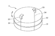
引掛プラグ3は、室内の天井に配置された照明機器等の取り付けに用いられる引掛シーリングに対応するプラグである。図2は引掛プラグ3の詳細構成を示す斜視図である。図2に示すように、引掛プラグ3は、プロジェクタ装置1の使用時の上面に固定され円柱形の外観を呈する第1基部31と、第1基部31に対して回動自在に取り付けられ円柱形の外観を呈する第2基部32と、第2基部32にL字状に形成された導電係止片33と、導電係止片33と電源部とを接続する導電線34とで形成される。
【0028】
そして引掛プラグ3は、室内の天井に配置された引掛シーリングに接続される。図3は引掛プラグ3と引掛シーリングとの接続状態を示す図である。図3に示すように、導電係止片33を引掛シーリングDに設けられた係止孔D1に挿入し、回動して係止することにより、引掛プラグ3を引掛シーリングDに接続する。
【0029】
このように引掛プラグ3は、引掛シーリングDと接続されることにより、プロジェクタ装置1を天井に取り付ける取付手段として機能すると共に、導電係止片33から導電線34を介して電源部に電力を供給するための電源接続手段として機能する。なお、プロジェクタ装置1は、天井に取り付けられた後に、第2基部32を第1基部31に対して相対的に回動して、投射レンズの方向(映像光を投射する方向)を調節することができる。
【0030】
スポットライト4は、光源部41と傘部42とで構成される。光源部41は電源部から電力を受けて照明を行なう。傘部42は照明領域を絞る役割を果たし、また、傘部42はプロジェクタ装置1に対して可動に取り付けられる。従ってスポットライト4は、傘部42の方向を調節することにより、室内の一部領域を選択的に照明することが可能である。なお、後述するように、スポットライト4は、映像の鑑賞時に、映像光の投射領域以外の領域を選択的に照明して、必要領域の照明を行なうために用いられる。このように、映像光の投射領域以外の領域を選択的に照明すれば、投射される映像を劣化させることはない。
【0031】
室内灯5は、カバー51と、カバー51の内部に配置された光源部(図示せず)とで構成される。この光源部は電源部から電力を受けて、室内のほぼ全域の照明を行なう。室内灯5は、主に、映像の非鑑賞時に室内を照明するために用いられる。
【0032】
B.プロジェクタ装置の使用形態
次に、以上のように構成されたプロジェクタ装置1の使用形態の一例について説明する。図4は、プロジェクタ装置1を室内Rで使用する例を示した図である。
【0033】
図4に示すように、プロジェクタ装置1は室内Rの天井Cに取り付けられる。前述のとおり、プロジェクタ1は、天井Cに配設された引掛シーリングDに引掛プラグ3を接続することで、天井Cに取り付けられる。
【0034】
そしてプロジェクタ装置1は、室内Rの壁Wに配置されるスクリーンSに向けて光学像を拡大投射する。ここで、一般に、テーブルT、家具F、装飾品O等は室内Rの床Lに近い空間に配置されるため、天井Cに取り付けられるプロジェクタ装置1によれば、光学像の投射領域を容易に確保することができ、スクリーンSの設置領域の確保を容易にする。
【0035】
また、プロジェクタ装置1は、映像の鑑賞時(光学像の投射時)にスポットライト4で映像光の投射領域以外の領域、例えばテーブルTや部屋の共有者Pを選択的に照明することができる。従って、観察者Vは、例えば、プロジェクタ装置1を操作するためのリモコンEの操作を容易に行なうことができ、またテーブルT上に置かれた飲料Fを誤って溢してしまうようなことはない。また、映像を観察しない共有者Pは、スポットライト4からの照明により、例えば読書などを行なうこと可能となる。なお、スポットライト4は映像光の投射領域以外の領域を選択的に照明するため、スクリーンSに投射される映像を劣化させることはない。
【0036】
また、プロジェクタ装置1は、映像の非鑑賞時(光学像の非投射時)には、室内灯5で室内Rの全体を照明することができる。従って、映像を鑑賞しないときには、観察者V及び共有者Pは、通常の生活を行なうことができる。
【0037】
2.変形実施形態
引掛プラグ4の形状は、上記実施形態の構成に限られることなく、天井に配置される引掛シーリング又は引掛埋込ローゼット等の形状に対応して選定することができる。
【0038】
また、引掛プラグ4の他に補助的取付手段を用いることも可能である。例えば、引掛シーリングDに備えられた取付金具に、補助取付手段としてのチェーン等を係合するようにしても良い。
【0039】
また、スポットライト4及び室内灯5についても、それぞれが果たすべき機能を備える限り、特に上記実施形態の構成に限定されない。
【0040】
更に、以上の実施形態では、液晶方式のプロジェクタ装置を示したが、これに限られることなく、例えば、デジタルマイクロミラーデバイス方式やCRT方式のプロジェクタ装置等にも本発明が適用可能である。
【0041】
【発明の効果】
室内の天井に取り付けるための取付手段と、室内の天井に配置された電力供給用のコンセントに接続するための電源接続手段とを備えてプロジェクタ装置を構成したので、プロジェクタ装置を取付手段を用いて天井に取り付けることができ、室内における生活者の移動スペースを害することなくプロジェクタ装置を設置することができる。また、天井に配置される引掛シーリングや引掛埋込ローゼット等の電力供給用コンセントに電源接続手段を接続することで、容易に電力供給を受けることができる。
【0042】
また、電源接続手段をコンセントに対応するプラグで構成することにより、コンセントにプラグを接続することで、煩雑なくコンセントから電力供給を受けることができる。
【0043】
また、取付手段及び電源接続手段をコンセントに対応するプラグで構成することにより、コンセントにプラグを接続することで、取り付けと電源接続を同時に行なうことができ、電源及び天井への設置場所の確保や施工の煩わしさを解消することができる。
【0044】
また、このプロジェクタ装置に、室内を照明するための照明手段を備えることにより、照明装置に用いられるコンセントにプロジェクタ装置の電源接続手段を接続した場合でも、同時に室内の照明を確保することが可能となる。
【0045】
更に、照明手段を、映像光の投射領域以外の領域を選択的に照明できるようにすることにより、照明手段で投射領域以外の領域、例えば観察者の近傍を選択的に照明することにより、観察者は不自由なくリモコン等の操作や飲食を行なうことが可能となり、一方、投射領域は照明されないのでスクリーンに投射される映像を劣化させることはない。
【図面の簡単な説明】
【図1】(A)は本実施形態に係るプロジェクタ装置1の使用時における斜め上方から見た外観を示す斜視図であり、(B)は同プロジェクタ装置の使用時における斜め下方からみた外観を示す斜視図である。
【図2】プロジェクタ装置1の引掛プラグ3の詳細構成を示す斜視図である。
【図3】プロジェクタ装置1の引掛プラグ3と引掛シーリングとの接続状態を示す図である。
【図4】プロジェクタ装置1を室内Rで使用する例を示した図である。
【符号の説明】
1 プロジェクタ装置
2 投射レンズ
3 引掛プラグ
4 スポットライト
5 室内灯
D 引掛シーリング
S スクリーン[0001]
TECHNICAL FIELD OF THE INVENTION
The present invention relates to a projector device, and more particularly, to a projector device used by being arranged on a ceiling in a room.
[0002]
[Prior art]
2. Description of the Related Art Projector devices that project video images and computer images have been reduced in size, weight, and image quality due to recent advances in image display panel technology. In general households, the Internet and DVD have become widespread, and there is an increasing need to view these images through a projector device.
[0003]
[Problems to be solved by the invention]
However, at present, the projector device is used only by some enthusiasts and users who can afford the indoor space. The reasons are as follows.
[0004]
{Circle around (1)} Although the size of the projector device has been reduced as described above, it is not preferable to permanently install the projector device in a space where a consumer moves. Further, even when the projector device is installed only at the time of use, it is complicated to secure an installation space every time the projector device is used.
[0005]
{Circle around (2)} In order to appreciate the image of the projector device, it is necessary to secure a space for installing the screen, but it is not always easy to secure this space in a living room which is a multipurpose and shared space. . That is, the installation space for the screen is generally secured on or near the wall surface, but in this position furniture such as storage and displays such as a display for producing a sense of life are usually arranged at this position. In many cases, the elimination of such furniture and fixtures impairs the mental satisfaction of consumers, and it is difficult to secure a space for installing the screen.
[0006]
{Circle over (3)} In order to ensure the contrast of the image projected on the screen, a certain degree of “darkness” is required in the projection area of the image light projected from the projector device. However, in a multipurpose and shared space such as a living room, it is difficult to secure “darkness” for a long time.
[0007]
{Circle around (4)} Further, the “darkness” itself mentally reduces the enjoyment of watching images in the living room.
[0008]
To summarize the above, (1) and (2) are problems relating to “installation space”, and (3) and (4) are problems relating to “brightness”.
[0009]
SUMMARY OF THE INVENTION The present invention has been made in view of such problems, and has as its object to provide a projector device and a projector device which solves the problem of "installation space" of a screen. It is an object of the present invention to provide a projector device that solves the problem of “brightness” when viewing a video by the projector device.
[0010]
[Means for Solving the Problems]
In order to solve the above problems, a projector device of the present invention is a projector device for projecting image light, comprising: a mounting means for mounting on a ceiling in a room; and a power supply outlet arranged on the ceiling in the room. And power supply connecting means for connecting to the power supply (claim 1).
[0011]
According to this, it is possible to mount the projector device on the ceiling in the room by the mounting means, and to install the projector device without impairing the moving space of the consumer in the room. Also, by installing the projector device in the upper part of the room in this way, the screen can be easily installed in the upper part of the room (mainly at or near a wall surface), and the screen can be easily installed while avoiding furniture and fixtures. It is possible to do.
[0012]
Further, by connecting the power supply connecting means to a power supply outlet such as a hanging ceiling or a hanging buried rosette arranged on the ceiling, power can be easily received.
[0013]
Further, in this projector device, it is desirable that the power supply connection means is a plug corresponding to an outlet.
[0014]
According to this, by connecting the plug to the outlet, power can be supplied from the outlet without any trouble. As the plug, for example, a hook plug corresponding to a hook ceiling or a hooking embedded rosette can be used. The plug may be provided with a cable connection function with a signal cable for video, audio, or the like, an antenna cable, or the like. Further, the projector device may be provided with a receiving unit for wirelessly receiving a video signal, so that the video signal can be wirelessly received.
[0015]
Further, in this projector device, it is desirable that the attaching means and the power supply connecting means are plugs corresponding to an outlet.
[0016]
According to this, by connecting the plug to the outlet, mounting and power connection can be performed at the same time, and it is possible to secure a power supply and an installation place on a ceiling and to eliminate troublesome work. In this case, for example, a hook ceiling or a hooking embedded rosette may be used as an outlet, and the plug may be a corresponding hook plug. In addition, a plug may be used as the main mounting means, and other auxiliary mounting means may be provided in order to prevent falling and ensure safety. As the auxiliary mounting means, a chain, a string, or the like that is mounted on a mounting bracket disposed on the ceiling may be used.
[0017]
Further, the plug may have a rotation function. According to this, the projector can be freely rotated with the projector mounted on the ceiling, and the projection direction can be arbitrarily selected.
[0018]
Further, it is desirable that these projector devices include an illuminating unit for illuminating the room (claim 4).
[0019]
According to this, even when the power supply connection means of the projector device is connected to the outlet used for the lighting device, it is possible to simultaneously secure indoor lighting. Further, it is preferable that the illuminating means is illuminating means for illuminating the projector device downward. According to this, it is possible to prevent the projector device itself from blocking the light path of the illumination.
[0020]
Further, in this projector device, it is desirable that the illuminating means can selectively illuminate an area other than the area where the image light is projected.
[0021]
According to this, by selectively illuminating an area other than the projection area of the image light with the illumination means, for example, the vicinity of the observer, the observer can operate the remote control or eat and drink without inconvenience, On the other hand, since the projection area is not illuminated, the image does not deteriorate.
[0022]
It is preferable that the illuminating means have both a function of illuminating the entire room and a function of selectively illuminating an area other than the projection area of the image light. According to this, when observing an image, an area other than the projection area of the image light can be selectively illuminated, and when not observing the image, the entire room can be illuminated. Further, in this case, the projection of the image from the projector device and the switching of the illumination may be linked. That is, when projecting an image, an area other than the projection area of the image light may be selectively illuminated, and when not projecting an image, the illumination may be automatically switched so as to illuminate the entire room.
[0023]
BEST MODE FOR CARRYING OUT THE INVENTION
A preferred embodiment of the present invention will be described with reference to the drawings.
[0024]
1. First Embodiment A. Configuration of Projector Apparatus FIG. 1A is a perspective view showing the appearance of the projector apparatus according to the present embodiment when viewed from obliquely above, and FIG. FIG. 2 is a perspective view showing an appearance of the device viewed from obliquely below.
[0025]
As shown in FIG. 1, similarly to a known projector device, the projector device 1 includes, for example, an optical system (not shown) including a light source, a dichroic mirror, a mirror, an LCD panel, a color combining prism, and the like, and an external power receiving device. It mainly includes a power supply unit (not shown) that supplies the generated power to each unit of the projector device 1 and a
[0026]
Known optical systems, power supplies, and
[0027]
The hooking
[0028]
Then, the
[0029]
As described above, the hooking
[0030]
The spotlight 4 includes a
[0031]
The
[0032]
B. Usage pattern of projector apparatus Next, an example of a usage pattern of the projector apparatus 1 configured as described above will be described. FIG. 4 is a diagram illustrating an example in which the projector device 1 is used in a room R.
[0033]
As shown in FIG. 4, the projector device 1 is mounted on a ceiling C of a room R. As described above, the projector 1 is attached to the ceiling C by connecting the hanging
[0034]
Then, the projector device 1 enlarges and projects the optical image toward the screen S arranged on the wall W of the room R. Here, in general, the table T, the furniture F, the ornaments O, and the like are arranged in a space close to the floor L of the room R. Therefore, according to the projector device 1 mounted on the ceiling C, the projection area of the optical image can be easily set. Thus, it is possible to secure the installation area of the screen S easily.
[0035]
Further, the projector device 1 can selectively illuminate an area other than the projection area of the image light, for example, the table T or the sharer P of the room, with the spotlight 4 when watching the image (when projecting the optical image). . Therefore, the observer V can easily operate the remote controller E for operating the projector device 1, for example, and the viewer F can not accidentally overflow the beverage F placed on the table T. Absent. Also, the sharer P who does not observe the video can read, for example, by reading from the spotlight 4. Since the spotlight 4 selectively illuminates an area other than the projection area of the image light, the image projected on the screen S does not deteriorate.
[0036]
In addition, the projector device 1 can illuminate the entire room R with the
[0037]
2. Modified embodiment The shape of the hook plug 4 is not limited to the configuration of the above-described embodiment, and can be selected according to the shape of a hook ceiling or a hooking embedded rosette arranged on the ceiling.
[0038]
It is also possible to use auxiliary mounting means other than the hook plug 4. For example, a chain or the like as auxiliary mounting means may be engaged with a mounting bracket provided on the hooking ceiling D.
[0039]
Further, the spotlight 4 and the
[0040]
Further, in the above embodiments, the liquid crystal type projector device has been described. However, the present invention is not limited to this, and the present invention can be applied to, for example, a digital micromirror device type or CRT type projector device.
[0041]
【The invention's effect】
Since the projector device is provided with mounting means for mounting on the ceiling in the room and power supply connecting means for connecting to a power supply outlet arranged on the ceiling in the room, the projector device is mounted using the mounting means. The projector device can be mounted on a ceiling, and the projector device can be installed without harming a moving space of a consumer in a room. In addition, power can be easily supplied by connecting the power supply connection means to a power supply outlet such as a hook ceiling or a hook-in embedded rosette arranged on the ceiling.
[0042]
In addition, by configuring the power supply connection means with a plug corresponding to the outlet, the plug can be connected to the outlet, so that power can be supplied from the outlet without complication.
[0043]
In addition, by configuring the mounting means and the power connection means with plugs corresponding to the outlets, by connecting the plugs to the outlets, mounting and power connection can be performed at the same time. The trouble of construction can be eliminated.
[0044]
Further, by providing the projector device with illumination means for illuminating the interior of the room, even when the power supply connection means of the projector device is connected to an outlet used for the illumination device, it is possible to simultaneously secure indoor illumination. Become.
[0045]
Furthermore, the illumination means can selectively illuminate an area other than the projection area of the image light, so that the illumination means selectively illuminates an area other than the projection area, for example, the vicinity of the observer, thereby enabling observation. The user can operate the remote controller and the like and eat and drink without any inconvenience. On the other hand, since the projection area is not illuminated, the image projected on the screen does not deteriorate.
[Brief description of the drawings]
FIG. 1A is a perspective view showing the appearance of a projector device 1 according to the present embodiment as viewed from obliquely above, and FIG. 1B is a perspective view of the projector device 1 as viewed from obliquely below during use. FIG.
FIG. 2 is a perspective view showing a detailed configuration of a
FIG. 3 is a view showing a connection state between a hooking
FIG. 4 is a diagram showing an example in which the projector device 1 is used in a room R.
[Explanation of symbols]
DESCRIPTION OF SYMBOLS 1
Claims (5)
室内の天井に取り付けるための取付手段と、
前記室内の天井に配置された電力供給用のコンセントに接続するための電源接続手段と、
を備えたことを特徴とするプロジェクタ装置。A projector device that projects video light,
Mounting means for mounting on the indoor ceiling,
Power connection means for connecting to a power supply outlet arranged on the ceiling in the room,
A projector device comprising:
前記電源接続手段は前記コンセントに対応するプラグであることを特徴とするプロジェクタ装置。The projector device according to claim 1,
The projector device, wherein the power connection means is a plug corresponding to the outlet.
前記取付手段及び前記電源接続手段は前記コンセントに対応するプラグであることを特徴とするプロジェクタ装置。The projector device according to claim 1,
2. The projector device according to claim 1, wherein the attachment unit and the power connection unit are plugs corresponding to the outlet.
前記室内を照明するための照明手段を備えたことを特徴とするプロジェクタ装置。The projector device according to claim 1, wherein
A projector device comprising an illumination unit for illuminating the room.
前記照明手段は前記映像光を投射する領域以外の領域を選択的に照明できることを特徴とするプロジェクタ装置。The projector device according to claim 4, wherein
The projector device according to claim 1, wherein the illuminating means can selectively illuminate an area other than an area where the image light is projected.
Priority Applications (1)
| Application Number | Priority Date | Filing Date | Title |
|---|---|---|---|
| JP2003022640A JP2004233692A (en) | 2003-01-30 | 2003-01-30 | Projector device |
Applications Claiming Priority (1)
| Application Number | Priority Date | Filing Date | Title |
|---|---|---|---|
| JP2003022640A JP2004233692A (en) | 2003-01-30 | 2003-01-30 | Projector device |
Publications (1)
| Publication Number | Publication Date |
|---|---|
| JP2004233692A true JP2004233692A (en) | 2004-08-19 |
Family
ID=32951661
Family Applications (1)
| Application Number | Title | Priority Date | Filing Date |
|---|---|---|---|
| JP2003022640A Pending JP2004233692A (en) | 2003-01-30 | 2003-01-30 | Projector device |
Country Status (1)
| Country | Link |
|---|---|
| JP (1) | JP2004233692A (en) |
Cited By (8)
| Publication number | Priority date | Publication date | Assignee | Title |
|---|---|---|---|---|
| JP2015022147A (en) * | 2013-07-19 | 2015-02-02 | セイコーエプソン株式会社 | Projector |
| JP2015022148A (en) * | 2013-07-19 | 2015-02-02 | セイコーエプソン株式会社 | Projector |
| US20170280116A1 (en) * | 2016-03-28 | 2017-09-28 | Seiko Epson Corporation | Projector |
| WO2017163291A1 (en) * | 2016-03-24 | 2017-09-28 | パナソニックIpマネジメント株式会社 | Translucent screen, projection system, and method for controlling translucent screen |
| US10171780B2 (en) | 2014-12-26 | 2019-01-01 | Maxell, Ltd. | Lighting apparatus |
| US10197233B2 (en) | 2014-12-26 | 2019-02-05 | Maxell, Ltd. | Illumination device |
| US10260691B2 (en) | 2014-12-26 | 2019-04-16 | Maxell, Ltd. | Illumination apparatus |
| US10262519B2 (en) | 2014-12-26 | 2019-04-16 | Maxell, Ltd. | Lighting apparatus |
-
2003
- 2003-01-30 JP JP2003022640A patent/JP2004233692A/en active Pending
Cited By (18)
| Publication number | Priority date | Publication date | Assignee | Title |
|---|---|---|---|---|
| JP2015022147A (en) * | 2013-07-19 | 2015-02-02 | セイコーエプソン株式会社 | Projector |
| JP2015022148A (en) * | 2013-07-19 | 2015-02-02 | セイコーエプソン株式会社 | Projector |
| US10602104B2 (en) | 2014-12-26 | 2020-03-24 | Maxell, Ltd. | Lighting apparatus |
| US10699552B2 (en) | 2014-12-26 | 2020-06-30 | Maxell, Ltd. | Lighting apparatus |
| US11606851B2 (en) | 2014-12-26 | 2023-03-14 | Maxell, Ltd. | Lighting apparatus |
| US10171780B2 (en) | 2014-12-26 | 2019-01-01 | Maxell, Ltd. | Lighting apparatus |
| US10997846B2 (en) | 2014-12-26 | 2021-05-04 | Maxell, Ltd. | Lighting apparatus |
| US10708559B2 (en) | 2014-12-26 | 2020-07-07 | Maxell, Ltd. | Lighting apparatus |
| US10197233B2 (en) | 2014-12-26 | 2019-02-05 | Maxell, Ltd. | Illumination device |
| US10260691B2 (en) | 2014-12-26 | 2019-04-16 | Maxell, Ltd. | Illumination apparatus |
| US10262519B2 (en) | 2014-12-26 | 2019-04-16 | Maxell, Ltd. | Lighting apparatus |
| JPWO2017163291A1 (en) * | 2016-03-24 | 2019-01-10 | パナソニックIpマネジメント株式会社 | Transmission screen, projection system, and transmission screen control method |
| US10527921B2 (en) | 2016-03-24 | 2020-01-07 | Panasonic Intellectual Property Management Co., Ltd. | Transparent screen, projection system, and method of controlling transparent screen |
| US20190025692A1 (en) * | 2016-03-24 | 2019-01-24 | Panasonic Intellectual Property Management Co., Ltd. | Transparent screen, projection system, and method of controlling transparent screen |
| WO2017163291A1 (en) * | 2016-03-24 | 2017-09-28 | パナソニックIpマネジメント株式会社 | Translucent screen, projection system, and method for controlling translucent screen |
| US20170280116A1 (en) * | 2016-03-28 | 2017-09-28 | Seiko Epson Corporation | Projector |
| US10771750B2 (en) * | 2016-03-28 | 2020-09-08 | Seiko Epson Corporation | Projector |
| CN107238998A (en) * | 2016-03-28 | 2017-10-10 | 精工爱普生株式会社 | Projecting apparatus |
Similar Documents
| Publication | Publication Date | Title |
|---|---|---|
| US9832430B2 (en) | Device having built-in digital data device powered by unlimited power source for light device | |
| US9366420B2 (en) | Lighting equipment and desk with illumination function | |
| US7621643B2 (en) | Projection apparatus, ceiling hanging hardware for projection apparatus, and method of controlling operation of projection apparatus | |
| CN101842632A (en) | Illuminating device and image display device | |
| JP2008185757A (en) | Projector, projection system and luminaire | |
| US8107017B2 (en) | Combination display apparatus | |
| JP2005099588A (en) | Projection type image display system and connector device | |
| US11153543B2 (en) | Illuminating apparatus | |
| JPH07264527A (en) | Liquid crystal projector | |
| JP2004233692A (en) | Projector device | |
| JP2004184768A (en) | Projector device | |
| KR20160144253A (en) | System based on the ambient lighting and its method | |
| JP2003015221A (en) | Projection device | |
| JP2004078150A (en) | Projection display device | |
| KR100549309B1 (en) | Variable size hanger of flat panel video display device | |
| CN206946187U (en) | Illuminating projection all-in-one | |
| WO2013155207A1 (en) | System and methods for a highly integrated teleprompter | |
| JPH09139905A (en) | Projection display device | |
| CN209355105U (en) | It can show ceiling mounting type lamps and lanterns | |
| JP2002169497A (en) | Advertisement provision equipment and method, information memory medium, advertisement supply system and method | |
| US20060146294A1 (en) | Device and method for arranging a display | |
| JP2003298978A (en) | Video projection system | |
| WO2007129145A2 (en) | Home television expandable for wireless acquisition, and for user-selected viewing, of surveillance and security images | |
| US20210123593A1 (en) | Overhead projector lighting | |
| KR200331344Y1 (en) | Seat mounted with LCD monitor by holding structure in concert hall |
Legal Events
| Date | Code | Title | Description |
|---|---|---|---|
| A621 | Written request for application examination |
Free format text: JAPANESE INTERMEDIATE CODE: A621 Effective date: 20060118 |
|
| A977 | Report on retrieval |
Free format text: JAPANESE INTERMEDIATE CODE: A971007 Effective date: 20090120 |
|
| A131 | Notification of reasons for refusal |
Free format text: JAPANESE INTERMEDIATE CODE: A131 Effective date: 20090127 |
|
| A02 | Decision of refusal |
Free format text: JAPANESE INTERMEDIATE CODE: A02 Effective date: 20090602 |