JP2004233022A - Vaporizing type humidifier - Google Patents
Vaporizing type humidifier Download PDFInfo
- Publication number
- JP2004233022A JP2004233022A JP2003025578A JP2003025578A JP2004233022A JP 2004233022 A JP2004233022 A JP 2004233022A JP 2003025578 A JP2003025578 A JP 2003025578A JP 2003025578 A JP2003025578 A JP 2003025578A JP 2004233022 A JP2004233022 A JP 2004233022A
- Authority
- JP
- Japan
- Prior art keywords
- water
- water tank
- blower fan
- turned
- filter
- Prior art date
- Legal status (The legal status is an assumption and is not a legal conclusion. Google has not performed a legal analysis and makes no representation as to the accuracy of the status listed.)
- Pending
Links
Images

Landscapes
- Air Humidification (AREA)
Abstract
Description
【0001】
【発明の属する技術分野】
本発明は、吸水した気化フィルターに送風用ファンにより通風して加湿する気化式加湿機に関するものである。
【0002】
【従来の技術】
従来の気化式加湿機においては、水タンクと水槽とは常に水路で連通されており、水タンクに水が有る限り、気化フィルターは毛細管現象により水槽内の水を吸い上げて、常に濡れたままの状態に保たれる構成になっている。(例えば、特許文献1参照。)
【0003】
【特許文献1】
特開2000−356373号公報(第3−4頁、図1−図2)
【0004】
【発明が解決しようとする課題】
しかしながら、上記従来の気化式加湿機の場合、常時、気化フィルターが濡れたままの状態で加湿機を長期使用したり、あるいは水タンクに水を入れたまま長期保存したりすると、やがて気化フィルターにカビや雑菌等が繁殖したり、異臭が発生するといった不具合が生じる。
【0005】
本発明は、上記問題点を解消するためになされたもので、気化フィルターにカビや雑菌等が繁殖するのを抑制し、異臭の発生を防止できる気化式加湿機を提供することを目的としている。
【0006】
【課題を解決するための手段】
本発明の気化式加湿機は、吸込口と吹出口を形成した本体と、この本体内に設けた送風用ファン及び水槽と、前記水槽と水路で連通される水タンクと、前記水槽内の水に下部が浸される気化フィルターを有し、前記水槽は水タンクからの水を受けて常時一定量の水を収容し、前記送風用ファンは前記吸込口より吸気して前記気化フィルターに通風し、前記気化フィルターより湿気を奪って加湿された空気を前記吹出口より吹き出すようにした気化式加湿機において、運転オフ時に閉じて前記水槽と水タンクを連通させる水路を遮断する開閉手段を設けたものである。
【0007】
【発明の実施の形態】
実施の形態1.
以下、本発明の実施の形態1を図面に基づいて説明する。
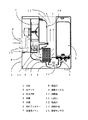
図1は本発明による実施の形態1の気化式加湿機を示す断面図である。
図1に示すように、合成樹脂で構成された本体1の側面に吸込口8を設け、上面に吹出口12を設けている。本体1の内部に着脱可能な水タンク2より水受け部3及び管状の水路5を介して給水される水槽4を設けている。水槽4は水受け部3と水路5を介して連通され、常時一定量の水を収容する。この水槽4内に下部が水に浸るように設けられ、毛細管現象で水を吸い上げる気化フィルター6が設けられている。また、前記本体1内には前記気化フィルター6に送風する送風用ファン7が設けられている。また、前記本体1の吸込口8と吹出口12の近傍には通過する空気中の湿度を検出する湿度センサA9と湿度センサB14がそれぞれ設けられている。前述の送風用ファン7の吐出口11には加熱体10が設けられている。前記水路5には、例えば電磁弁等からなる開閉手段13が設けられている。この開閉手段13は、加湿機の運転オフ時には閉じ、運転オン時には開放するように構成されている。
【0008】
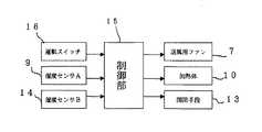
図2は上記の構成からなる実施の形態1の気化式加湿機の制御回路のブロック図である。
図2に示すように、制御部15は、運転スイッチ16、湿度センサA9、湿度センサB14からの入力情報に基づき、送風用ファン7、加熱体10、開閉手段13をオンオフ制御する。
【0009】
次に、上記の構成からなる実施の形態1の動作について説明する。
水タンク2を本体1にセットすると、水タンク2内の水は水受け部3に落水する。水受け部3の水は水路5を通り、閉じられた開閉手段13まで流れ込み、定常水位を保持する。運転スイッチ16をオンすることにより、制御部15が開閉手段13をオン(開放)させると、水受け部3内の水が開閉手段13及び水路5を通り、水槽4内に給水され、定常水位を保持する。制御部15は、一定時間経過後、送風用ファン7をオンさせて、吸込口8から吸い込まれた乾燥空気が気化フィルター6に送風される。このとき、制御部15は吸込口8内に設けられている湿度センサA9からの入力情報により湿度が低いと判断した場合は、加熱体10をオンさせ、吸い込まれた乾燥空気が熱せられ温風となって気化フィルター6に送風される。気化フィルター6は毛細管現象により水槽4内の水を吸い上げており、送られてきた乾燥空気との熱交換により乾燥空気を湿らせる。湿った空気は吹出口12より本体1外へ放出され、加湿運転が行われる。
一方、運転スイッチ16をオフすると、開閉手段13はオフ(閉)して水路5を遮断する。
【0010】
次に、上記実施の形態1における運転スイッチオフ後の制御動作について説明する。図3は、本発明の実施の形態1の気化式加湿機の運転スイッチオフ後の制御動作を示すフローチャートである。
まず、ステップS1により運転スイッチがオフされると、ステップS2に移行する。ステップS2では、制御部15から開閉手段13をオフさせる信号が出力されて、開閉手段13が閉じ、水路5を遮断して、ステップS3に移行する。ステップS3では、上述の制御部15から送風用ファン7と加熱体10をオンさせ、温風による気化フィルター6の強制乾燥を開始する。
【0011】
次に、ステップS4では、気化フィルター6から送られてくる空気を湿度センサB14にて湿度T1を測定し、測定結果は制御部15に対して出力する。ステップS5では、ステップS4で測定された湿度が30%RHに対し大きい場合は気化フィルター6が濡れていると判定してステップ4に移行し、再度湿度センサB14にて湿度T1を測定する。ステップS4での測定された湿度が30%RHに対し少ない場合は、気化フィルター6の乾燥が終了していると判定してステップ6へ移行する。ステップ6では、送風用ファン7と加熱体10をオフさせてステップ7へ移行し、気化フィルター6の強制乾燥を停止する。
【0012】
以上のように、上記実施の形態1によれば、前記水路5には例えば電磁弁等からなる開閉手段13が設けられており、この開閉手段13は、加湿機の運転スイッチ15のオフ時に閉じて水路5を遮断するように構成されているので、運転をオフする度に水路5は遮断される。このため、水タンク2に水を入れたまま放置しても、水タンク2内の水が無くなるまで水槽4に給水されるようなことはなくなり、水槽4内の水が蒸発してなくなれば、気化フィルター6は吸水できなくなる。
よって、従来のように気化フィルター6が常に濡れた状態に保たれ、カビや雑菌等が繁殖したり、異臭が発生するといった問題点を解消できる。また、開閉手段13を閉じると同時に、前記送風用ファン7と加熱体10をオンさせて、温風により前記気化フィルター6を強制乾燥させるので、吹出口12近傍に設けた湿度センサB14で吹き出し空気の湿度をモニターすることで、気化フィルターの乾燥終了を検出し、強制乾燥を適当な時期に停止させることができる。これにより、無駄な電力の使用を抑えて、電気代の節約や省エネが図れる。
【0013】
なお、上記実施の形態1では、吹出口12近傍に設けた湿度センサB14で吹き出し空気の湿度をモニターすることで、気化フィルターの乾燥終了を検出し、強制乾燥を停止するようにしたが、送風ファン7及び加熱体10を一定時間作動させることで、気化フィルター6の強制乾燥を停止させるようにしてもよい。
また、前記送風用ファン7と加熱体10による前記気化フィルター6の強制乾燥は必ずしも必要な制御事項ではなく、少なくとも運転オフ時に水路5を遮断する開閉手段13を設けていればよいものである。
【0014】
【発明の効果】
以上のように本発明によれば、運転オフ時に、前記水槽と水タンクを連通させる水路を遮断する開閉手段を設けたことにより、長期使用あるいは水タンク内に水をいれたまま長期保存したような場合においても、気化フィルターにカビや雑菌が繁殖するのを抑制でき、異臭の発生を防止できるという効果が得られる。
【図面の簡単な説明】
【図1】本発明による実施の形態1の気化式加湿機を示す断面図である。
【図2】本発明による実施の形態1の気化式加湿機の制御回路のブロック図である。
【図3】本発明による実施の形態1の気化式加湿機の運転スイッチオフ後の制御動作を示すフローチャートである。
【符号の説明】
1 本体
2 水タンク
4 水槽
5 水路
6 気化フィルター
7 送風用ファン
8 吸込口
9 湿度センサA
10 加熱体
11 吐出口
12 吹出口
13 開閉手段
14 湿度センサB[0001]
TECHNICAL FIELD OF THE INVENTION
TECHNICAL FIELD The present invention relates to a vaporizing humidifier that humidifies a vaporized filter that has absorbed water by passing air through a fan.
[0002]
[Prior art]
In a conventional evaporative humidifier, the water tank and the water tank are always in communication with each other through a water channel, and as long as there is water in the water tank, the evaporating filter sucks up the water in the water tank by a capillary phenomenon and keeps the water constantly wet. It is configured to be kept in a state. (For example, refer to
[0003]
[Patent Document 1]
JP-A-2000-356373 (page 3-4, FIGS. 1-2)
[0004]
[Problems to be solved by the invention]
However, in the case of the above-mentioned conventional vaporizing humidifier, if the humidifier is used for a long time while the vaporizing filter remains wet, or if it is stored for a long time with water in the water tank, the vaporizing filter eventually becomes Problems such as the growth of molds and various germs and the generation of offensive odor occur.
[0005]
The present invention has been made to solve the above problems, and it is an object of the present invention to provide a vaporizing humidifier that can suppress the growth of mold and various germs on a vaporizing filter and can prevent the generation of an odor. .
[0006]
[Means for Solving the Problems]
The evaporative humidifier of the present invention includes a main body having an inlet and an outlet, a blower fan and a water tank provided in the main body, a water tank communicating with the water tank through a water channel, and a water tank in the water tank. The water tank receives water from the water tank and always contains a certain amount of water, and the blower fan draws air from the suction port to ventilate the vaporization filter. An evaporative humidifier that removes moisture from the evaporator filter and blows out humidified air from the outlet is provided with an opening / closing unit that closes when operation is off and shuts off a water channel that connects the water tank and the water tank. Things.
[0007]
BEST MODE FOR CARRYING OUT THE INVENTION
Hereinafter,
FIG. 1 is a sectional view showing an evaporative humidifier according to a first embodiment of the present invention.
As shown in FIG. 1, an
[0008]
FIG. 2 is a block diagram of a control circuit of the evaporative humidifier of the first embodiment having the above configuration.
As shown in FIG. 2, the control unit 15 controls on / off of the
[0009]
Next, the operation of the first embodiment having the above configuration will be described.
When the
On the other hand, when the operation switch 16 is turned off, the opening /
[0010]
Next, a control operation after the operation switch is turned off in the first embodiment will be described. FIG. 3 is a flowchart showing a control operation after the operation switch of the evaporative humidifier according to the first embodiment of the present invention is turned off.
First, when the operation switch is turned off in step S1, the process proceeds to step S2. In step S2, a signal for turning off the opening /
[0011]
Next, in step S4, the humidity T1 is measured by the humidity sensor B14 for the air sent from the
[0012]
As described above, according to the first embodiment, the
Therefore, it is possible to solve the problems that the vaporizing
[0013]
In the first embodiment, the humidity sensor B14 provided near the
Further, the forced drying of the vaporizing
[0014]
【The invention's effect】
As described above, according to the present invention, when the operation is turned off, the water tank and the water tank are provided with the opening / closing means that shuts off the water path, so that the water tank is used for a long time or stored for a long time with water in the water tank. Even in such a case, it is possible to obtain an effect that it is possible to suppress the growth of mold and various germs on the vaporizing filter, and to prevent the generation of an odor.
[Brief description of the drawings]
FIG. 1 is a sectional view showing an evaporative humidifier according to a first embodiment of the present invention.
FIG. 2 is a block diagram of a control circuit of the evaporative humidifier according to the first embodiment of the present invention.
FIG. 3 is a flowchart showing a control operation of the evaporative humidifier according to the first embodiment of the present invention after the operation switch is turned off.
[Explanation of symbols]
DESCRIPTION OF
DESCRIPTION OF
Claims (5)
Priority Applications (1)
| Application Number | Priority Date | Filing Date | Title |
|---|---|---|---|
| JP2003025578A JP2004233022A (en) | 2003-02-03 | 2003-02-03 | Vaporizing type humidifier |
Applications Claiming Priority (1)
| Application Number | Priority Date | Filing Date | Title |
|---|---|---|---|
| JP2003025578A JP2004233022A (en) | 2003-02-03 | 2003-02-03 | Vaporizing type humidifier |
Publications (2)
| Publication Number | Publication Date |
|---|---|
| JP2004233022A true JP2004233022A (en) | 2004-08-19 |
| JP2004233022A5 JP2004233022A5 (en) | 2005-10-27 |
Family
ID=32953819
Family Applications (1)
| Application Number | Title | Priority Date | Filing Date |
|---|---|---|---|
| JP2003025578A Pending JP2004233022A (en) | 2003-02-03 | 2003-02-03 | Vaporizing type humidifier |
Country Status (1)
| Country | Link |
|---|---|
| JP (1) | JP2004233022A (en) |
Cited By (7)
| Publication number | Priority date | Publication date | Assignee | Title |
|---|---|---|---|---|
| JP2006200833A (en) * | 2005-01-21 | 2006-08-03 | Matsushita Electric Ind Co Ltd | Humidifier, and reclaiming method for humidification structure |
| JP2009014250A (en) * | 2007-07-04 | 2009-01-22 | Sanyo Electric Co Ltd | Air conditioning device, air sterilizing device, and control method and control program of air conditioning device |
| WO2010062003A1 (en) * | 2008-11-28 | 2010-06-03 | Lg Electronics Inc. | Humidifier |
| KR101276044B1 (en) | 2012-01-18 | 2013-06-20 | 이인영 | Humidifier with automatic drying function |
| JP2018071819A (en) * | 2016-10-25 | 2018-05-10 | ダイニチ工業株式会社 | Humidifier |
| KR102183009B1 (en) * | 2020-08-21 | 2020-11-25 | 주식회사 삼화에이스 | Control method of evaporative humidifier |
| CN112665061A (en) * | 2020-06-04 | 2021-04-16 | 青岛海尔空调器有限总公司 | Humidifying device and air conditioner |
-
2003
- 2003-02-03 JP JP2003025578A patent/JP2004233022A/en active Pending
Cited By (10)
| Publication number | Priority date | Publication date | Assignee | Title |
|---|---|---|---|---|
| JP2006200833A (en) * | 2005-01-21 | 2006-08-03 | Matsushita Electric Ind Co Ltd | Humidifier, and reclaiming method for humidification structure |
| JP4696566B2 (en) * | 2005-01-21 | 2011-06-08 | パナソニック株式会社 | Humidifier and method for regenerating humidified structure |
| JP2009014250A (en) * | 2007-07-04 | 2009-01-22 | Sanyo Electric Co Ltd | Air conditioning device, air sterilizing device, and control method and control program of air conditioning device |
| WO2010062003A1 (en) * | 2008-11-28 | 2010-06-03 | Lg Electronics Inc. | Humidifier |
| US8672299B2 (en) | 2008-11-28 | 2014-03-18 | Lg Electronics Inc. | Humidifier |
| KR101532576B1 (en) * | 2008-11-28 | 2015-06-30 | 엘지전자 주식회사 | Humidifier |
| KR101276044B1 (en) | 2012-01-18 | 2013-06-20 | 이인영 | Humidifier with automatic drying function |
| JP2018071819A (en) * | 2016-10-25 | 2018-05-10 | ダイニチ工業株式会社 | Humidifier |
| CN112665061A (en) * | 2020-06-04 | 2021-04-16 | 青岛海尔空调器有限总公司 | Humidifying device and air conditioner |
| KR102183009B1 (en) * | 2020-08-21 | 2020-11-25 | 주식회사 삼화에이스 | Control method of evaporative humidifier |
Similar Documents
| Publication | Publication Date | Title |
|---|---|---|
| JP4478464B2 (en) | Humidifier | |
| KR20130092093A (en) | Humidifier with automatic drying function and humidity control method | |
| JP2008183283A (en) | Bathroom cleaning device | |
| KR101923449B1 (en) | Humidifier | |
| JP2002106969A (en) | Hot air heater with humidifying function | |
| JP2004233022A (en) | Vaporizing type humidifier | |
| JP2002327940A (en) | Air conditioner | |
| JP3837651B2 (en) | Vaporizing humidifier | |
| JP2001116303A (en) | Humidifier | |
| KR100329929B1 (en) | Air conditioner having a humidifier unit | |
| JP2004347297A (en) | Humidifier | |
| JP2005021428A (en) | Sauna apparatus and sauna system | |
| JP2006300388A (en) | Bathroom heating device with mist sauna function | |
| JP4770621B2 (en) | Air purifier with humidification function | |
| JP3788215B2 (en) | Vaporizing humidifier | |
| KR102647362B1 (en) | Multi-function storage system performing preheating mode by measuring condenser temperature and method of perfoming preheating mode using thereof | |
| JP2003222361A (en) | Humidifier | |
| KR102599051B1 (en) | Multi-function storage system performing preheating mode by measuring water supply tank temperature and method of perfoming preheating mode using thereof | |
| JP2008264387A (en) | Hair dryer | |
| JP2004233022A5 (en) | ||
| JPH0742978A (en) | Humidifier | |
| KR102116963B1 (en) | Multifunctional storage system including heat pump unit having water supply portion and Method of preheating using the same | |
| JP3963825B2 (en) | Humidifier | |
| JP2004012029A (en) | Humidifier | |
| JP4292896B2 (en) | Sauna equipment |
Legal Events
| Date | Code | Title | Description |
|---|---|---|---|
| RD01 | Notification of change of attorney |
Effective date: 20040712 Free format text: JAPANESE INTERMEDIATE CODE: A7421 |
|
| RD01 | Notification of change of attorney |
Effective date: 20050715 Free format text: JAPANESE INTERMEDIATE CODE: A7421 |
|
| A521 | Written amendment |
Free format text: JAPANESE INTERMEDIATE CODE: A523 Effective date: 20050726 |
|
| A621 | Written request for application examination |
Free format text: JAPANESE INTERMEDIATE CODE: A621 Effective date: 20050726 |
|
| A977 | Report on retrieval |
Effective date: 20071011 Free format text: JAPANESE INTERMEDIATE CODE: A971007 |
|
| A131 | Notification of reasons for refusal |
Effective date: 20071016 Free format text: JAPANESE INTERMEDIATE CODE: A131 |
|
| A02 | Decision of refusal |
Effective date: 20080401 Free format text: JAPANESE INTERMEDIATE CODE: A02 |