JP2004232972A - Blow-out opening and air conditioning method using the same - Google Patents
Blow-out opening and air conditioning method using the same Download PDFInfo
- Publication number
- JP2004232972A JP2004232972A JP2003022577A JP2003022577A JP2004232972A JP 2004232972 A JP2004232972 A JP 2004232972A JP 2003022577 A JP2003022577 A JP 2003022577A JP 2003022577 A JP2003022577 A JP 2003022577A JP 2004232972 A JP2004232972 A JP 2004232972A
- Authority
- JP
- Japan
- Prior art keywords
- outlet
- airflow
- main body
- control member
- air
- Prior art date
- Legal status (The legal status is an assumption and is not a legal conclusion. Google has not performed a legal analysis and makes no representation as to the accuracy of the status listed.)
- Granted
Links
Images


Landscapes
- Air-Flow Control Members (AREA)
- Air Conditioning Control Device (AREA)
Abstract
Description
【0001】
【発明の属する技術分野】
本発明は、壁や天井等に設けられ、冷気または暖気の吹き出しに使用される吹出口およびこれを用いた空調方法に関する。
【0002】
【従来の技術】
従来、吹出方向を水平にした筒状の吹出口本体の内部に、回動可能に支持されたリング状の枠体に水平に設けられた複数の制御羽根を有する気流制御部材を設けた吹出口がある(特許文献1参照)。
【0003】
枠体は、吹出口本体の内径より少し小さく形成され、両側部を吹出口本体の内周部に回動可能に支持されている。両回動軸には、気流制御部材をそれぞれ逆廻り方向に付勢するねじりばねが設けられ、一方のねじりばねは、30℃〜35℃の温度で変態する形状記憶合金により形成されている。
【0004】
特許文献1の第2図に示すように、吹出口本体の上端部にはストッパが設けられ、第2図における右廻り方向に付勢された気流制御部材は、ストッパに当接して停止する。このとき、気流制御部材は、吹出口本体の前端面に略平行に配置され、枠体と吹出口本体の内面との間の隙間は最小になっている。また、枠体に設けられた制御羽根が水平に配置されるので、気流は、吹出口本体から水平に吹出される。
【0005】
気流制御部材が左廻り方向に回動すると、枠体および各制御羽根も回動する。例えば、気流制御部材が30°回動すると、枠体および各制御羽根も30°回動し、気流は水平方向に対して下方に吹出される。
【0006】
【特許文献1】
実開平3−27543号公報 (第1−2頁、第2図)
【0007】
【発明が解決しようとする課題】
しかしながら、特許文献1に記載された気流制御部材は、各制御羽根が30°回動しても、各制御羽根によって偏向された気流が、枠体と吹出口本体の内面との間の隙間を通過する気流の影響を受けるので、吹出口から流出する気流は、25°程度しか向きが変わらない。また、各制御羽根を30°以上回動させても、隙間を通過する気流が多くなるだけなので、吹出口から流出する気流の向きは、25°程度までしか制御できないと考えられていた。
近年、例えば、スタンドの座席の後側の下部に取り付け、座板の下方および背板に沿って斜め上方に吹き出す場合のように、前記従来の吹出口よりも気流を大きく偏向させ、広い範囲に気流を吹き出すことが可能な吹出口が要求されているが、特許文献1に記載された気流制御部材は、上述したように、両側部に設けられた回動軸を中心に回動することにより、枠体と吹出口本体の内面との間の隙間が大きくなり、この隙間が所定の大きさを超えると気流の方向を制御できなくなるので、広い範囲に気流を吹き出すことができないという問題がある。
そこで本発明が解決しようとする課題は、隙間を通過する気流を制限しながら気流角度の制御範囲を大きくした吹出口およびこれを用いた空調方法を提供することにある。
【0008】
【課題を解決するための手段】
前記課題を解決するため、本発明の吹出口は、冷暖房に用いられる筒状の吹出口本体と、この吹出口本体の内周部に回動可能に支持された枠体およびこの枠体に設けられた複数の制御羽根を有する気流制御部材とを備えた吹出口において、前記気流制御部材の回動範囲の途中位置には、前記枠体が、前記吹出口本体に最接近する位置が含まれていることを特徴とする。
【0009】
吹出口の形状は特に限定しないが、円形や矩形のものも含まれる。
枠体と吹出口本体の内面との間の隙間の大きさは、気流制御部材の回動角度に応じて変動し、この隙間が大きくなると、隙間を通過する風向を制御されていない気流が増加するとともに、気流制御部材の内部を通過する気流が減少するので、回動角度が所定の角度を超えると、気流全体の制御を正確に行なうことができなくなる。この隙間および角度は、気流制御部材を吹出口の中心線に直交する面上に配置したときに最小となる。
【0010】
本発明において、枠体と吹出口本体の内面との間の隙間は、気流制御部材の回動範囲の途中位置において最小となるように構成している。すなわち、前記隙間は、気流制御部材が吹出口本体の中心線に直交する状態にあるときに最小になるが、前記気流制御部材の回動範囲は、この直交状態を基準として両方向に回動できるように設定されている。
【0011】
気流制御部材の外側端が両方向に回動することができるので、気流の制御可能範囲を従来の吹出口よりも拡げることができる。
【0012】
前記吹出口本体に、前記気流制御部材を所定角度に回動させる作動手段を設けると、温度や風量に応じて制御羽根を自動的に作動させることができるので、風向の調整や切り替えを簡単に行うことができる。
ここで、作動手段には、例えば、モータ等の駆動手段を、温度や風量を検知するセンサに接続したものが含まれる。
【0013】
前記制御羽根を、前記枠体に直交する方向に対し、傾斜配置させると、気流の吹出方向を、枠体に直交する方向に対して偏向させて吹き出すことができ、風向を任意の範囲に設定することができる。
枠体の傾斜角度が大きくなると、複数の制御羽根のうちの半分が上流側に移動するので、枠体の内部を通過した気流が吹出口本体の内面に当たりやすくなり、気流の制御が困難になるが、制御羽根を枠体に直交する方向に対し傾斜配置させておくことによって、枠体の傾斜角度を小さく保持したまま気流の向きを大きく偏向させることができ、また、枠体の内部を通過した気流が、吹出口本体の内面に当たりにくくなるので、気流の制御を正確に行うことができる。
【0014】
前記気流制御部材の回動範囲を、前記気流制御部材が前記吹出口本体の外側に突出しない範囲に設定すると、枠体と吹出口本体の内面との間の隙間が大きくなり過ぎることがなくなり、この隙間を通過する気流が多くなり過ぎることがなく、気流の制御を正確に行うことができる。また、気流制御部材が吹出口からはみ出さないので、例えば、スタンドの座席の後方の足下に吹出口を設置したような場合のように、観客等との干渉による事故や故障を未然に防止することができる。
なお、外側に突出しないとは、枠体の厚み以上に突出しないことをいう。枠体に一定の厚みがある場合には、気流制御部材が、前記厚みの範囲内で吹出口本体から突出しても、枠体と吹出口本体の内面との間の隙間が大きくなり過ぎることがなく、また、観客等との干渉も少ない。
【0015】
前記作動手段に、感温素子を用い、この感温素子を、前記吹出口本体の中央部に設けると、風向を温度に応じて自動的に切り替えることができる。感温素子とは、所定の温度によって変形する性質を有するものをいい、例えば、形状記憶合金ばね、形状記憶樹脂、またはワックスセンサ等が含まれる。
【0016】
感温素子は、例えば、バイアスばねとともに使用することができる。感温素子を用いることにより、所定の温度に応じて気流制御部材を回動させることができる。
【0017】
また、作動手段が吹出口の中央部に設けられているので、周辺部に比較して、外部からの熱損失が少ない気流を直接当てることができ、気流制御部材を確実かつ迅速に作動させることができる。
【0018】
前記吹出口本体の上流側に、絞り部を設けると、吹出口本体に流入する気流は、絞り部によって絞られ、吹出口本体の中央部を通過するので、枠体と吹出口本体の内面との間の隙間から流出する気流を減らすとともに外部からの熱損失の影響を少なくすることができる。絞り部は、吹出口本体の上流側端部を絞って形成することもできるが、吹出口とは別に形成して、これを上流側端部に取り付ける場合も含まれる。
【0019】
特に、感温素子が中央部に設けられている場合に絞り部を設けると、吹出口本体に流入する気流を感温素子に確実に当てて、感温素子の動作の確実性を向上させることができる。
【0020】
前記吹出口本体の前記気流制御部材より上流側に、前記作動手段を支持するとともに、前記気流制御部材に当接可能な板状部材からなるストッパを設けると、1つの部材に作動手段の支持とストッパとの機能を設けているので部材の数を減らすことができる。また、ストッパの平面部を気流に平行に配置することにより気流の影響を受けにくくなり、騒音の発生を抑制できる。
【0021】
本発明の吹出口を用いた空調方法は、請求項5に記載の吹出口を用いた空調方法であって、前記吹出口を、階段状に配置された各座席の後方にそれぞれ配置し、吹出温度を制御することによって、暖房時には、前記座席の座板の下側に向かって気流を吹き出し、冷房時には、前記座席の背板に沿わせて気流を上方に吹き出すことを特徴とする。
【0022】
各吹出口を、主縦管から分岐して設けられた多数の末端枝管に接続し、主縦管に気流を吹き出すことにより、各吹出口本体内にそれぞれ気流を通過させることができる。各吹出口本体内の感温素子は、この気流を検知して作動手段を作動させ、風向を調整する。すなわち、暖房時には水平吹出を行って座板の下側に気流を通過させ、冷房時には斜め上方に気流を吹き出し、冷えた気流を背板に沿わせて上昇させることができ、暖房時と冷房時に各々適した吹出気流を得られる。
【0023】
温度によって、気流の向きを制御するので、吹出口の数が増えても、各吹出口から同じ方向に気流を吹き出すことができ、各作動手段を精度よく制御することができる。
【0024】
【発明の実施の形態】
以下、本発明の実施の形態について説明する。
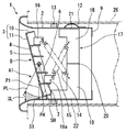
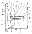
図1は本発明の吹出口の側断面図、図2は同平断面図、図3は同正面図である。図1〜図3に示すように、本発明の吹出口1は、冷暖房に用いられる筒状の吹出口本体2と、この吹出口本体2の内周部に両側部を回動可能に支持された枠体3およびこの枠体3に設けられた4枚の制御羽根4〜7を有する気流制御部材8とを備えている。
【0025】
吹出口本体2は略円筒状に形成され、下流側端部は断面円弧状に形成されている。また、吹出口本体2の上流側端部には、円環平板状の絞り部材9(絞り部)が設けられている。
吹出口本体2の外周部には、固定用ばね12が周方向の3箇所に設けられ、また、パッキン13が全周に設けられている。
【0026】
枠体3および制御羽根4〜7は、1枚の円板をプレス加工することにより形成される。枠体3は、円筒状に形成された外周部10と、外周部10の下流側端を接続する円板部11とを備え、制御羽根4〜7は、円板部11の5箇所にC字状に形成した切り込み部の内側部分を、それぞれ立て起こして形成されている。
【0027】
制御羽根4〜7の立て起こし角度は、円板部11に対して例えば78°に設定され、各制御羽根4〜7は平行に配置されている。また、制御羽根4,7には、作動手段の一例であるバイアスばね14および形状記憶合金ばね15(感温素子)の一端を取り付ける固定金具16,16aがねじ部材等を用いて固定されている。
【0028】
外周部10の両側部は、吹出口本体2に樹脂製の回動軸31,32を介して回動可能に取り付けられている。回動軸31,32が樹脂製なので、錆を防止することができ、また、回動時に、金属製の吹出口本体2および気流制御部材8との当接部分から、きしみ音が発生することを防止できる。
【0029】
吹出口本体2の気流制御部材8より上流側には、バイアスばね14および形状記憶合金ばね15を支持するとともに、気流制御部材8の上端および下端に当接可能な板状部材からなるストッパ17が設けられている。
【0030】
ストッパ17は、一枚の板状部材を複数箇所で屈曲させて形成したもので、側面視してコ字状に形成されている。それぞれL字状に形成された上ストッパ部18と下ストッパ部19とは、左右に所定距離をあけて平行に配置され、上ストッパ部18と下ストッパ部19の間には、水平部20が形成されている。また、上ストッパ部18の上端部と下ストッパ部19の下端部はそれぞれ屈曲して、吹出口本体2の内周面に取り付けられる固定部21,22をそれぞれ形成している。
【0031】
上ストッパ部18の中間部と気流制御部材8の下側の固定金具16aは、形状記憶合金ばね15により接続されている。また、下ストッパ部19の中間部と上側の固定金具16は、バイアスばね14により接続されている。形状記憶合金ばね15およびバイアスばね14は、側面視したときに交差配置されており、かかる構成によって、ばねの自由長およびストロークを大きくとれるので、作動力の設定が簡単にできる。
【0032】
図4(A)、(B)は、本発明の吹出口の使用状態を示す側断面図である。
形状記憶合金ばね15の動作温度は、例えば、20〜27℃に設定されている。
【0033】
図4(A)に示すように、形状記憶合金ばね15の動作温度より気流の温度の方が高い状態においては、形状記憶合金ばね15が収縮して、バイアスばね14が伸長し、気流制御部材8の下部を上流側に付勢する。気流制御部材8は、左廻り方向に回動して、下端部をストッパ17の下端部に当接させた状態で停止する。このときの気流制御部材8の円板部11は、鉛直面に対して−12°傾斜している。また、制御羽根4〜7は、水平に配置されている。
【0034】
図4(B)に示すように、形状記憶合金ばね15の動作温度より気流の温度の方が低くなると、形状記憶合金ばね15が伸長して、バイアスばね14が収縮し、気流制御部材8の上部を上流側に付勢する。気流制御部材8は、右廻り方向に回動して、上端部をストッパ17の上端部に当接させた状態で停止する。このときの気流制御部材8の円板部11は、鉛直面に対して30°傾斜している。また、制御羽根4〜7は、水平面に対して42°傾斜している。このときの気流制御部材8の前端は、吹出口本体2の前端より少し上流側に配置されており、吹出口本体2の外側には突出しない。
【0035】
絞り部材9の内周端は、気流制御部材8が回動したときの外周部10の外側端より半径方向内側に設定されているので、ほとんどの気流は、気流制御部材8の制御羽根4〜7に当たり、吹出方向を制御される。
【0036】
図1に示すように、気流制御部材8の回動範囲A1の途中位置には、枠体3が、吹出口本体2に最接近する位置P1が含まれている。位置P1は、枠体3の円板部11が回動して鉛直に配置されたときの位置である。
【0037】
気流制御部材8は、位置PHから位置P1を経由して位置PLまで回動する。このときの枠体3と吹出口本体2の内面との間の隙間の距離Sは、SHから徐々に小さくなってS1となり、ここから徐々に大きくなってSLとなる。
【0038】
隙間の距離SがSLを超えると、気流の制御が困難になるため、通常は、S1からSLの範囲(約30°)でしか気流制御は行われていないが、本実施の形態においては、S1からSHの範囲(約12°)も回動できるので、気流の制御を確実に行いながら回動角度を大きくすることができる。PHの位置は、−30°程度まで大きくすることができるので、必要に応じてはさらに回動角度を大きく設定して、制御範囲を拡げることができる。
なお、気流の制御可能な範囲は、外周部10の幅等により変動するが、本実施の形態においては、約35°の範囲で気流を制御できることを実験により確認している。
【0039】
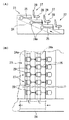
次に、本発明の吹出口1を階段状座席23に適用した状態について説明する。
図5(A)は、本発明の吹出口を階段状座席に取り付けた状態を示す断面図、(B)は、同吹出口を階段状座席に取り付けた状態を示す平面図である。
階段状座席23は、例えば、競技場やコンサートホール等に用いられており、このような場所では、広い室内全体の空調を行うより、各座席の近傍に空調空気を吹き出す方が効率よく冷暖房を管理することができる。
【0040】
階段状座席23は鉄筋コンクリート製で、空調ダクトは、通路に沿って内部に主縦管24を傾斜配置し、主縦管24から、階段状に配置された各座席27の下側を横方向に通過するように横引枝管24aを配置し、横引枝管24aから前側の座席27の後方の下部に末端枝管25を開口させて配置している。末端枝管25の開口部は、吹出口1の取付孔となる。
【0041】
図1に示すように、吹出口1の取付孔には、スパイラルダクト26が配置され、吹出口1は、スパイラルダクト26に嵌入され、固定用ばね12とパッキン13をスパイラルダクト26の内周面に当接させて固定される。
【0042】
主縦管24に送られた気流は、横引枝管24aおよび末端枝管25を介して吹出口1から吹き出される。このとき、吹出口本体2内を通過する気流の温度が変化すると、バイアスばね14および形状記憶合金ばね15の一方が収縮して他方が伸長する。このようにして作動手段を駆動することにより風向を切り替える。
【0043】
吹出口1は、暖房時には図4(A)と同じ状態で水平吹出を行い、気流が前の座席27の座板28の下側を通過するように風向を切り替え、足元を暖める。また、冷房時には図4(B)と同じ状態で斜め上方に気流を吹き出し、前の座席27の背板29に気流が当たるように風向を切り替え、冷えた気流を背板29に沿わせて上方に吹き出す。
【0044】
配管がコンクリート内に埋設され、吹出口も圧力損失が少ない構造となっているので、騒音が小さく、屋内の劇場やコンサートホール等の静粛性を要求される用途にも好適に用いることができる。
【0045】
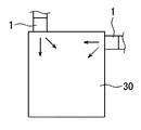
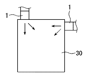
図6は、本発明の吹出口の他の使用状態を示す説明図である。図6に示すように、吹出口1は、偏向気流が要求され、かつ広い範囲で調整可能であることが要求される場所、例えば、室内の天井と壁部の接合部分等にも使用することができる。
【0046】
吹出口1を、部屋30の天井であって、壁に近接する位置に設けた場合には、暖房時に直下方に吹き出し、冷房時に斜め下方に吹き出すように調整することができる。回動角度の変更は、ストッパの形状を当接位置に合わせて作成することにより対応することができる。
【0047】
また、壁部の上部であって、天井に近接する位置に設けた場合は、冷房時に側方に吹き出し、暖房時に斜め下方に吹き出すように、調整することができる。冷房時と暖房時の吹き出し方向を逆にすることは、バイアスばねと形状記憶合金ばねの取り付け位置を逆にすることにより対応することができる。
また、制御羽根の円板部に対する取付角度を変更することにより風向の制御範囲を変更することもできる。
【0048】
なお、バイアスばね14および形状記憶合金ばね15の代わりにワックスセンサや形状記憶樹脂製のばねを用いることができる。ワックスセンサとは、シリンダ内に封入したワックスが、所定の温度で状態変化してその体積を変えることを利用して、ロッドを伸縮させる装置である。ワックスセンサも形状記憶合金ばねと同様に細長く形成されているので、吹出口本体2の中央部に交差配置することができ、気流の温度変化を敏感に検知して、気流制御部材の配置を確実に切り替えることができる。
【0049】
ワックスセンサは、形状記憶合金ばねと比べ、作動温度範囲が狭く、また、作動温度のばらつきが小さいので、気流制御部材を精度よく作動させることができ、また、作動力が大きいので、吹出口が大型サイズになった場合には、ワックスセンサの個数を増やすことなく気流制御部材を確実に作動させることができる。
【0050】
また、作動手段として、モータを用いることも可能である。モータは、所定角度で停止可能なサーボモータを用いることが好ましく、かかる構成によって、風向を切り替えるだけではなく、任意の向きに調整することができる。
【0051】
モータには、温度や風量を検知するセンサを設けることができ、かかる構成によって、温度により吹出方向を切り替えるだけではなく、風量により吹出方向を変化させる構成にすることができる。
【0052】
【実施例】
本発明の吹出口(直径100mmのもの)を用いて発生騒音を測定した。測定は無響室内で行い、測定位置は、吹出口中心軸から水平に45°方向、距離1mの地点とした。周波数補正回路(A特性)を通して測定を行う精密騒音計を用い、測定時の室内の環境暗騒音は4.6(dB)であった。以下にその結果を示す。
【0053】
【表1】
斜め上吹出の風量20m3/hのときの発生騒音は、4.3dBとなっているが、これは、暗騒音が測定されたもので、実際に吹出口が発生する騒音は、もっと小さいと考えられる。
通常、暖房時は20m3/h、冷房時は35m3/hの風量で運転を行うので、ほとんど暗騒音と同じ大きさとなり、コンサートホール等の音響効果を損なうことはないと考えられる。
【0055】
【発明の効果】
本発明によれば次の効果を奏する。
(1)本発明の吹出口は、気流制御部材の回動範囲の途中位置に、枠体が吹出口本体に最接近する位置を含めたので、枠体と吹出口本体の内面との間の隙間が、所定範囲内に収まる状態で、回動範囲を拡げることができ、気流制御部材の外側を通過する気流を減少させ、隙間を通過する気流を制限しながら気流角度の制御範囲を大きくすることができる。
(2)吹出口本体に、気流制御部材を所定角度に回動させる作動手段を設けると、温度や風量に応じて制御羽根を自動的に作動させることができるので、風向の調整や切り替えを簡単に行うことができる。
(3)制御羽根を、枠体に直交する方向に対し、傾斜配置させると、気流の吹出方向を、枠体に直交する方向に対して偏向させて吹き出すことができ、風向を任意の範囲に設定することができる。
(4)気流制御部材を吹出口本体の外側に突出しない範囲で回動させると、隙間を通過する気流が多くなり過ぎることを防止するとともに、観客等との干渉による事故や故障を未然に防止することができる。
(5)作動手段に、感温素子を用いて吹出口本体の中央部に設けると、風向を温度に応じて自動的に切り替えることができる。
(6)吹出口本体の上流側に絞り部材を設けると、吹出口本体に流入する気流が絞り部材によって絞られ、吹出口本体の中央部を通過するので、枠体と吹出口本体の内面との間の隙間から流出する気流を減らすとともに外部からの熱損失の影響を少なくすることができる。特に、感温素子が中央部に設けられている場合に絞り部を設けると、気流を感温素子に確実に当てて、感温素子の動作の確実性を向上させることができる。
(7)作動手段を支持するとともに、気流制御部材に当接可能な板状部材からなるストッパを設けると、1つの部材に作動手段の支持とストッパとの機能を設けているので部材の数を減らすことができる。また、ストッパの平面部を気流に平行に配置すると、気流の影響を受けにくくなり、騒音の発生を防止できる。
(8)本発明の吹出口の空調方法は、請求項5に記載の吹出口を用いた空調方法であって、吹出口を、階段状に配置された各座席の後方にそれぞれ配置し、吹出温度を制御することによって、暖房時には、前記座席の座板の下側に向かって気流を吹き出し、冷房時には、前記座席の背板に沿わせて気流を上方に吹き出すので、吹出口の数が増えても、各吹出口から同じ方向に気流を吹き出すことができ、各作動手段を精度よく制御することができ、暖房時と冷房時に各々適した吹出気流を得ることができ、快適な空調を実現することができる。
【図面の簡単な説明】
【図1】本発明の吹出口の側断面図である。
【図2】同吹出口の平断面図である。
【図3】同吹出口の正面図である。
【図4】(A)、(B)は、本発明の吹出口の使用状態を示す側断面図である。
【図5】(A)は、本発明の吹出口を階段状座席に取り付けた状態を示す断面図、(B)は、同吹出口を階段状座席に取り付けた状態を示す平面図である。
【図6】本発明の吹出口の他の使用状態を示す説明図である。
【符号の説明】
1 吹出口
2 吹出口本体
3 枠体
4〜7 制御羽根
8 気流制御部材
9 絞り部材
10 外周部
11 円板部
12 固定用ばね
13 パッキン
14 バイアスばね
15 形状記憶合金ばね
16,16a 固定金具
17 ストッパ
18 上ストッパ部
19 下ストッパ部
20 水平部
21,22 固定部
23 階段状座席
24 主縦管
24a 横引枝管
25 末端枝管
26 スパイラルダクト
27 座席
28 座板
29 背板
30 部屋
31 回動軸
32 回動軸[0001]
TECHNICAL FIELD OF THE INVENTION
The present invention relates to an air outlet provided on a wall, a ceiling, or the like and used for blowing cool air or warm air, and an air conditioning method using the air outlet.
[0002]
[Prior art]
Conventionally, an air outlet provided with an airflow control member having a plurality of control blades horizontally provided in a rotatably supported ring-shaped frame inside a cylindrical outlet main body having a horizontal blowing direction. (See Patent Document 1).
[0003]
The frame is formed to be slightly smaller than the inner diameter of the outlet main body, and both sides are rotatably supported by the inner peripheral part of the outlet main body. A torsion spring for urging the airflow control member in the reverse rotation direction is provided on each of the rotating shafts, and one of the torsion springs is formed of a shape memory alloy that transforms at a temperature of 30 ° C to 35 ° C.
[0004]
As shown in FIG. 2 of
[0005]
When the airflow control member rotates counterclockwise, the frame and each control blade also rotate. For example, when the airflow control member rotates by 30 °, the frame and each control blade also rotate by 30 °, and the airflow is blown downward with respect to the horizontal direction.
[0006]
[Patent Document 1]
Japanese Utility Model Laid-Open Publication No. 3-27543 (page 1-2, FIG. 2)
[0007]
[Problems to be solved by the invention]
However, in the airflow control member described in
In recent years, for example, when attached to the lower portion of the rear side of the seat of the stand and blows obliquely upward below the seat plate and along the back plate, the airflow is largely deflected more than the conventional outlet, and a wide range is provided. Although an air outlet capable of blowing out an airflow is required, the airflow control member described in
Accordingly, an object of the present invention is to provide an air outlet having an increased air flow angle control range while restricting an air flow passing through a gap, and an air conditioning method using the same.
[0008]
[Means for Solving the Problems]
In order to solve the above problem, an air outlet of the present invention is provided on a cylindrical air outlet main body used for cooling and heating, a frame rotatably supported on an inner peripheral portion of the air outlet main body, and provided on the frame. And an airflow control member having a plurality of control blades provided at a position in the middle of a rotation range of the airflow control member, a position where the frame body comes closest to the air outlet body. It is characterized by having.
[0009]
The shape of the outlet is not particularly limited, but includes a circular or rectangular shape.
The size of the gap between the frame and the inner surface of the outlet main body fluctuates according to the rotation angle of the airflow control member. As this gap increases, the amount of airflow that does not control the wind direction passing through the gap increases. At the same time, the airflow passing through the airflow control member is reduced, so that if the rotation angle exceeds a predetermined angle, the entire airflow cannot be accurately controlled. The gap and the angle are minimized when the airflow control member is arranged on a plane orthogonal to the center line of the outlet.
[0010]
In the present invention, the gap between the frame body and the inner surface of the outlet main body is configured to be minimized at an intermediate position in the rotation range of the airflow control member. That is, the gap is minimized when the airflow control member is in a state perpendicular to the center line of the outlet main body, but the rotation range of the airflow control member can be rotated in both directions based on the orthogonal state. It is set as follows.
[0011]
Since the outer end of the airflow control member can rotate in both directions, the controllable range of the airflow can be expanded as compared with the conventional outlet.
[0012]
If the air outlet body is provided with an operating means for rotating the air flow control member at a predetermined angle, the control blades can be automatically operated according to the temperature and the air volume, so that adjustment and switching of the air direction can be easily performed. It can be carried out.
Here, the operating means includes, for example, a means in which a driving means such as a motor is connected to a sensor for detecting a temperature or an air volume.
[0013]
When the control blades are arranged obliquely with respect to a direction orthogonal to the frame, the airflow blowing direction can be deflected relative to the direction orthogonal to the frame and can be blown, and the wind direction is set to an arbitrary range. can do.
When the inclination angle of the frame body increases, half of the plurality of control blades move to the upstream side, so that the airflow that has passed through the inside of the frame body easily hits the inner surface of the outlet main body, making it difficult to control the airflow. However, by arranging the control blades at an angle to the direction perpendicular to the frame, the direction of the airflow can be largely deflected while keeping the tilt angle of the frame small, and the air passes through the inside of the frame. The flow of the blown air hardly hits the inner surface of the outlet main body, so that the airflow can be accurately controlled.
[0014]
When the rotation range of the airflow control member is set to a range in which the airflow control member does not protrude outside the outlet main body, the gap between the frame and the inner surface of the outlet main body does not become too large, The airflow passing through the gap does not become too large, and the airflow can be accurately controlled. In addition, since the airflow control member does not protrude from the outlet, it is possible to prevent accidents and breakdowns due to interference with spectators and the like, such as when the outlet is installed under the feet behind the seat of the stand. be able to.
In addition, not protruding outside means that it does not protrude beyond the thickness of the frame. When the frame has a certain thickness, the gap between the frame and the inner surface of the outlet main body may be too large even if the airflow control member projects from the outlet main body within the range of the thickness. There is no interference with the audience.
[0015]
If a temperature sensing element is used as the operating means and this temperature sensing element is provided at the center of the outlet main body, the wind direction can be automatically switched according to the temperature. The temperature-sensitive element has a property of being deformed by a predetermined temperature, and includes, for example, a shape memory alloy spring, a shape memory resin, a wax sensor, or the like.
[0016]
The temperature sensing element can be used, for example, with a bias spring. By using the temperature sensing element, the airflow control member can be rotated according to a predetermined temperature.
[0017]
Also, since the operating means is provided at the center of the outlet, it is possible to directly apply an airflow with less heat loss from the outside compared to the peripheral portion, and to operate the airflow control member reliably and quickly. Can be.
[0018]
When a throttle portion is provided on the upstream side of the outlet main body, the airflow flowing into the outlet main body is throttled by the throttle portion and passes through the central portion of the outlet main body. And the effect of heat loss from outside can be reduced. The throttle portion can be formed by narrowing the upstream end of the outlet main body, but also includes a case where the throttle is formed separately from the outlet and attached to the upstream end.
[0019]
In particular, when the throttle portion is provided when the temperature-sensitive element is provided in the center portion, the airflow flowing into the outlet body is reliably applied to the temperature-sensitive element, thereby improving the reliability of the operation of the temperature-sensitive element. Can be.
[0020]
Supporting the operating means on the upstream side of the airflow control member of the outlet main body, and providing a stopper made of a plate-like member capable of contacting the airflow control member, provides support for the operating means in one member. Since the function as the stopper is provided, the number of members can be reduced. In addition, by arranging the flat portion of the stopper parallel to the airflow, the stopper is less likely to be affected by the airflow, thereby suppressing generation of noise.
[0021]
An air conditioning method using an air outlet according to the present invention is an air conditioning method using an air outlet according to
[0022]
Each of the outlets is connected to a number of end branch pipes provided by branching from the main vertical pipe, and an airflow can be blown out to the main vertical pipe to allow the airflow to pass through each of the outlet main bodies. The temperature sensing element in each outlet main body detects this air flow and activates the operating means to adjust the wind direction. In other words, during heating, horizontal blowing is performed to allow airflow to pass under the seat plate, and during cooling, airflow is blown diagonally upward, allowing the cooled airflow to rise along the back plate, and during heating and cooling. A suitable outlet airflow can be obtained.
[0023]
Since the direction of the airflow is controlled by the temperature, even if the number of outlets increases, the airflow can be blown out from each outlet in the same direction, and each operating means can be accurately controlled.
[0024]
BEST MODE FOR CARRYING OUT THE INVENTION
Hereinafter, embodiments of the present invention will be described.
FIG. 1 is a side sectional view of the outlet of the present invention, FIG. 2 is a plan sectional view thereof, and FIG. 3 is a front view thereof. As shown in FIGS. 1 to 3, an
[0025]
The outlet
On the outer peripheral portion of the outlet
[0026]
The
[0027]
The upright angle of the
[0028]
Both side portions of the outer
[0029]
On the upstream side of the
[0030]
The
[0031]
The middle part of the
[0032]
4 (A) and 4 (B) are side sectional views showing a use state of the outlet of the present invention.
The operating temperature of the shape
[0033]
As shown in FIG. 4A, in a state where the temperature of the airflow is higher than the operating temperature of the shape
[0034]
As shown in FIG. 4B, when the temperature of the airflow is lower than the operating temperature of the shape
[0035]
Since the inner peripheral end of the
[0036]
As shown in FIG. 1, a position P <b> 1 where the
[0037]
The
[0038]
If the distance S of the gap exceeds SL, it becomes difficult to control the airflow. Therefore, the airflow control is usually performed only in the range (about 30 °) from S1 to SL. However, in the present embodiment, Since the rotation in the range from S1 to SH (about 12 °) can also be performed, the rotation angle can be increased while reliably controlling the airflow. Since the position of the PH can be increased up to about −30 °, the control angle can be increased by further setting the rotation angle as needed.
Note that the controllable range of the airflow varies depending on the width of the outer
[0039]
Next, a state in which the
FIG. 5A is a cross-sectional view showing a state in which the outlet of the present invention is attached to a staircase seat, and FIG. 5B is a plan view showing a state in which the outlet is attached to a staircase seat.
The stair-shaped
[0040]
The step-
[0041]
As shown in FIG. 1, a
[0042]
The airflow sent to the main
[0043]
At the time of heating, the
[0044]
Since the pipe is buried in concrete and the outlet has a structure with low pressure loss, it can be suitably used for applications requiring low noise such as indoor theaters and concert halls.
[0045]
FIG. 6 is an explanatory view showing another use state of the outlet of the present invention. As shown in FIG. 6, the
[0046]
When the
[0047]
In addition, in the case of being provided above the wall portion and at a position close to the ceiling, adjustment can be made such that the air blows laterally during cooling and blows obliquely downward during heating. Reversing the blowing direction during cooling and heating can be handled by reversing the mounting positions of the bias spring and the shape memory alloy spring.
Further, the control range of the wind direction can be changed by changing the mounting angle of the control blade with respect to the disk portion.
[0048]
Note that a wax sensor or a spring made of a shape memory resin can be used instead of the
[0049]
The wax sensor has a narrower operating temperature range and a smaller variation in operating temperature than the shape memory alloy spring, so that the airflow control member can be operated with high accuracy. When the size becomes large, the airflow control member can be reliably operated without increasing the number of wax sensors.
[0050]
Further, a motor can be used as the operating means. As the motor, it is preferable to use a servomotor that can be stopped at a predetermined angle. With such a configuration, it is possible to adjust not only the wind direction but also an arbitrary direction.
[0051]
The motor can be provided with a sensor for detecting the temperature and the air volume. With this configuration, it is possible not only to switch the blowing direction according to the temperature but also to change the blowing direction according to the air volume.
[0052]
【Example】
The generated noise was measured using the outlet (having a diameter of 100 mm) of the present invention. The measurement was carried out in an anechoic room, and the measurement position was a point at a distance of 1 m in a 45 ° direction horizontally from the center axis of the outlet. A precision sound level meter that measures through a frequency correction circuit (A characteristic) was used, and the background noise in the room at the time of measurement was 4.6 (dB). The results are shown below.
[0053]
[Table 1]
The noise generated when the air volume of the obliquely upward airflow is 20 m 3 / h is 4.3 dB. This is a result of measurement of background noise, and it is assumed that the noise actually generated by the air outlet is smaller. Conceivable.
Normally, since the operation is performed with the air volume of 20 m 3 / h during heating and 35 m 3 / h during cooling, it is almost the same size as the background noise, and it is considered that the sound effect of the concert hall or the like is not impaired.
[0055]
【The invention's effect】
According to the present invention, the following effects can be obtained.
(1) Since the outlet of the present invention includes the position where the frame comes closest to the outlet main body in the middle of the rotation range of the airflow control member, the outlet between the frame and the inner surface of the outlet main body is included. With the gap within the predetermined range, the rotation range can be expanded, the airflow passing outside the airflow control member is reduced, and the control range of the airflow angle is increased while restricting the airflow passing through the gap. be able to.
(2) If the air outlet body is provided with an operating means for rotating the airflow control member at a predetermined angle, the control blades can be automatically operated according to the temperature and the air volume, so that adjustment and switching of the air direction can be easily performed. Can be done.
(3) When the control blades are arranged obliquely with respect to the direction perpendicular to the frame, the airflow can be blown out while being deflected in the direction perpendicular to the frame, and the wind direction can be set to an arbitrary range. Can be set.
(4) By rotating the airflow control member within a range that does not protrude outside the outlet main body, it is possible to prevent the airflow passing through the gap from becoming too large, and also to prevent accidents and breakdowns due to interference with spectators and the like. can do.
(5) If the operating means is provided at the center of the outlet main body using a temperature sensing element, the wind direction can be automatically switched according to the temperature.
(6) When the throttle member is provided on the upstream side of the outlet main body, the airflow flowing into the outlet main body is throttled by the throttle member and passes through the center of the outlet main body. And the effect of heat loss from outside can be reduced. In particular, if the throttle section is provided when the temperature sensing element is provided at the center, the airflow can be reliably applied to the temperature sensing element, and the operation reliability of the temperature sensing element can be improved.
(7) When a stopper made of a plate-like member that supports the operating means and can contact the airflow control member is provided, the function of supporting the operating means and the function of the stopper are provided in one member. Can be reduced. Further, when the flat portion of the stopper is arranged in parallel with the airflow, the stopper is less likely to be affected by the airflow, and the generation of noise can be prevented.
(8) An air-conditioning method for an air outlet according to the present invention is an air-conditioning method using the air outlet according to
[Brief description of the drawings]
FIG. 1 is a side sectional view of an outlet of the present invention.
FIG. 2 is a plan sectional view of the outlet.
FIG. 3 is a front view of the outlet.
FIGS. 4A and 4B are side sectional views showing a use state of the outlet of the present invention.
FIG. 5A is a cross-sectional view showing a state in which the outlet of the present invention is attached to a stair-step seat, and FIG. 5B is a plan view showing a state in which the outlet is attached to a step-like seat.
FIG. 6 is an explanatory view showing another use state of the outlet of the present invention.
[Explanation of symbols]
DESCRIPTION OF
Claims (8)
前記気流制御部材の回動範囲の途中位置には、前記枠体が、前記吹出口本体に最接近する位置が含まれていることを特徴とする吹出口。A cylindrical air outlet main body used for cooling and heating, an air flow control member having a frame rotatably supported on an inner peripheral portion of the air outlet main body and a plurality of control blades provided in the frame are provided. At the outlet
The air outlet, wherein a position where the frame body comes closest to the air outlet main body is included in a middle position of a rotation range of the air flow control member.
前記吹出口を、階段状に配置された各座席の後方にそれぞれ配置し、
吹出温度を制御することによって、暖房時には、前記座席の座板の下側に向かって気流を吹き出し、冷房時には、前記座席の背板に沿わせて気流を上方に吹き出すことを特徴とする空調方法。It is an air conditioning method using the outlet according to claim 5,
The outlet is arranged behind each of the seats arranged in steps,
An air conditioning method, comprising: controlling the blow-out temperature to blow out an airflow toward a lower side of a seat plate of the seat during heating, and blow the airflow upward along a back plate of the seat during cooling. .
Priority Applications (1)
| Application Number | Priority Date | Filing Date | Title |
|---|---|---|---|
| JP2003022577A JP4152207B2 (en) | 2003-01-30 | 2003-01-30 | Air outlet and air conditioning method using the same |
Applications Claiming Priority (1)
| Application Number | Priority Date | Filing Date | Title |
|---|---|---|---|
| JP2003022577A JP4152207B2 (en) | 2003-01-30 | 2003-01-30 | Air outlet and air conditioning method using the same |
Publications (2)
| Publication Number | Publication Date |
|---|---|
| JP2004232972A true JP2004232972A (en) | 2004-08-19 |
| JP4152207B2 JP4152207B2 (en) | 2008-09-17 |
Family
ID=32951615
Family Applications (1)
| Application Number | Title | Priority Date | Filing Date |
|---|---|---|---|
| JP2003022577A Expired - Fee Related JP4152207B2 (en) | 2003-01-30 | 2003-01-30 | Air outlet and air conditioning method using the same |
Country Status (1)
| Country | Link |
|---|---|
| JP (1) | JP4152207B2 (en) |
Cited By (3)
| Publication number | Priority date | Publication date | Assignee | Title |
|---|---|---|---|---|
| JP2008101849A (en) * | 2006-10-19 | 2008-05-01 | Ntt Facilities Inc | Air conditioning duct and air conditioning duct system |
| CN112303878A (en) * | 2020-09-17 | 2021-02-02 | 温州爱洁欧广告设计有限公司 | Air outlet auxiliary device of new-generation information technology central air conditioner |
| JP7423362B2 (en) | 2020-03-17 | 2024-01-29 | 株式会社竹中工務店 | Air outlet device |
Families Citing this family (1)
| Publication number | Priority date | Publication date | Assignee | Title |
|---|---|---|---|---|
| CN104964417A (en) * | 2015-06-23 | 2015-10-07 | 珠海格力电器股份有限公司 | Air outlet component and kitchen air conditioner |
-
2003
- 2003-01-30 JP JP2003022577A patent/JP4152207B2/en not_active Expired - Fee Related
Cited By (3)
| Publication number | Priority date | Publication date | Assignee | Title |
|---|---|---|---|---|
| JP2008101849A (en) * | 2006-10-19 | 2008-05-01 | Ntt Facilities Inc | Air conditioning duct and air conditioning duct system |
| JP7423362B2 (en) | 2020-03-17 | 2024-01-29 | 株式会社竹中工務店 | Air outlet device |
| CN112303878A (en) * | 2020-09-17 | 2021-02-02 | 温州爱洁欧广告设计有限公司 | Air outlet auxiliary device of new-generation information technology central air conditioner |
Also Published As
| Publication number | Publication date |
|---|---|
| JP4152207B2 (en) | 2008-09-17 |
Similar Documents
| Publication | Publication Date | Title |
|---|---|---|
| AU674049B2 (en) | Thermally controlled diffusers | |
| AU2006201346B2 (en) | Air Flow Control Device | |
| JP2007240059A (en) | Refrigerant flow distributor of heat exchanger for refrigerating device | |
| JP3239453U (en) | Industrial fan hanging mechanism | |
| US20190283544A1 (en) | Blowing device of air conditioner | |
| JP2004232972A (en) | Blow-out opening and air conditioning method using the same | |
| JP3612622B2 (en) | Indoor unit for air conditioner | |
| JP6238227B2 (en) | Air outlet device | |
| CA1119040A (en) | Regulator for a damper assembly | |
| KR100695482B1 (en) | Control apparatus for air volume flow rate | |
| KR101410029B1 (en) | Diffuser to control flowing shape of air which is supplied according to tempetature variation | |
| JP6849962B2 (en) | Damper device | |
| JP5318518B2 (en) | Air outlet device | |
| JPH06101892A (en) | Operation controller of air-conditioner | |
| CN208475594U (en) | A kind of novel blowing distributor | |
| JPH10332190A (en) | Cold air diffuser | |
| CA2554328C (en) | Air flow control device | |
| JP5271620B2 (en) | Humidification unit installation duct | |
| KR200414308Y1 (en) | Control apparatus for air volume flow rate | |
| JP3205900U (en) | Air conditioner for air conditioner | |
| JP2002130758A (en) | Ventilator | |
| JP7423362B2 (en) | Air outlet device | |
| JPH0634197A (en) | Air outlet device for air conditioner | |
| JP3241948B2 (en) | Automatic wind direction switching device | |
| JP2018200159A (en) | Flow rate control device |
Legal Events
| Date | Code | Title | Description |
|---|---|---|---|
| A621 | Written request for application examination |
Free format text: JAPANESE INTERMEDIATE CODE: A621 Effective date: 20051226 |
|
| A977 | Report on retrieval |
Free format text: JAPANESE INTERMEDIATE CODE: A971007 Effective date: 20070516 |
|
| A131 | Notification of reasons for refusal |
Free format text: JAPANESE INTERMEDIATE CODE: A131 Effective date: 20070612 |
|
| A521 | Written amendment |
Free format text: JAPANESE INTERMEDIATE CODE: A523 Effective date: 20070808 |
|
| A131 | Notification of reasons for refusal |
Free format text: JAPANESE INTERMEDIATE CODE: A131 Effective date: 20071023 |
|
| A521 | Written amendment |
Free format text: JAPANESE INTERMEDIATE CODE: A523 Effective date: 20071121 |
|
| A131 | Notification of reasons for refusal |
Free format text: JAPANESE INTERMEDIATE CODE: A131 Effective date: 20080507 |
|
| A521 | Written amendment |
Free format text: JAPANESE INTERMEDIATE CODE: A523 Effective date: 20080521 |
|
| TRDD | Decision of grant or rejection written | ||
| A01 | Written decision to grant a patent or to grant a registration (utility model) |
Free format text: JAPANESE INTERMEDIATE CODE: A01 Effective date: 20080617 |
|
| A01 | Written decision to grant a patent or to grant a registration (utility model) |
Free format text: JAPANESE INTERMEDIATE CODE: A01 |
|
| A61 | First payment of annual fees (during grant procedure) |
Free format text: JAPANESE INTERMEDIATE CODE: A61 Effective date: 20080701 |
|
| R150 | Certificate of patent or registration of utility model |
Free format text: JAPANESE INTERMEDIATE CODE: R150 |
|
| FPAY | Renewal fee payment (event date is renewal date of database) |
Free format text: PAYMENT UNTIL: 20110711 Year of fee payment: 3 |
|
| FPAY | Renewal fee payment (event date is renewal date of database) |
Free format text: PAYMENT UNTIL: 20110711 Year of fee payment: 3 |
|
| FPAY | Renewal fee payment (event date is renewal date of database) |
Free format text: PAYMENT UNTIL: 20120711 Year of fee payment: 4 |
|
| FPAY | Renewal fee payment (event date is renewal date of database) |
Free format text: PAYMENT UNTIL: 20130711 Year of fee payment: 5 |
|
| R250 | Receipt of annual fees |
Free format text: JAPANESE INTERMEDIATE CODE: R250 |
|
| R250 | Receipt of annual fees |
Free format text: JAPANESE INTERMEDIATE CODE: R250 |
|
| R250 | Receipt of annual fees |
Free format text: JAPANESE INTERMEDIATE CODE: R250 |
|
| R250 | Receipt of annual fees |
Free format text: JAPANESE INTERMEDIATE CODE: R250 |
|
| R250 | Receipt of annual fees |
Free format text: JAPANESE INTERMEDIATE CODE: R250 |
|
| LAPS | Cancellation because of no payment of annual fees |