JP2004232907A - Glow plug energization control device and glow plug energization control method - Google Patents
Glow plug energization control device and glow plug energization control method Download PDFInfo
- Publication number
- JP2004232907A JP2004232907A JP2003019797A JP2003019797A JP2004232907A JP 2004232907 A JP2004232907 A JP 2004232907A JP 2003019797 A JP2003019797 A JP 2003019797A JP 2003019797 A JP2003019797 A JP 2003019797A JP 2004232907 A JP2004232907 A JP 2004232907A
- Authority
- JP
- Japan
- Prior art keywords
- glow
- glow plug
- energization
- plug
- energization control
- Prior art date
- Legal status (The legal status is an assumption and is not a legal conclusion. Google has not performed a legal analysis and makes no representation as to the accuracy of the status listed.)
- Granted
Links
Images


Classifications
-
- F—MECHANICAL ENGINEERING; LIGHTING; HEATING; WEAPONS; BLASTING
- F02—COMBUSTION ENGINES; HOT-GAS OR COMBUSTION-PRODUCT ENGINE PLANTS
- F02P—IGNITION, OTHER THAN COMPRESSION IGNITION, FOR INTERNAL-COMBUSTION ENGINES; TESTING OF IGNITION TIMING IN COMPRESSION-IGNITION ENGINES
- F02P19/00—Incandescent ignition, e.g. during starting of internal combustion engines; Combination of incandescent and spark ignition
- F02P19/02—Incandescent ignition, e.g. during starting of internal combustion engines; Combination of incandescent and spark ignition electric, e.g. layout of circuits of apparatus having glowing plugs
- F02P19/021—Incandescent ignition, e.g. during starting of internal combustion engines; Combination of incandescent and spark ignition electric, e.g. layout of circuits of apparatus having glowing plugs characterised by power delivery controls
- F02P19/022—Incandescent ignition, e.g. during starting of internal combustion engines; Combination of incandescent and spark ignition electric, e.g. layout of circuits of apparatus having glowing plugs characterised by power delivery controls using intermittent current supply
-
- F—MECHANICAL ENGINEERING; LIGHTING; HEATING; WEAPONS; BLASTING
- F02—COMBUSTION ENGINES; HOT-GAS OR COMBUSTION-PRODUCT ENGINE PLANTS
- F02P—IGNITION, OTHER THAN COMPRESSION IGNITION, FOR INTERNAL-COMBUSTION ENGINES; TESTING OF IGNITION TIMING IN COMPRESSION-IGNITION ENGINES
- F02P19/00—Incandescent ignition, e.g. during starting of internal combustion engines; Combination of incandescent and spark ignition
- F02P19/02—Incandescent ignition, e.g. during starting of internal combustion engines; Combination of incandescent and spark ignition electric, e.g. layout of circuits of apparatus having glowing plugs
- F02P19/025—Incandescent ignition, e.g. during starting of internal combustion engines; Combination of incandescent and spark ignition electric, e.g. layout of circuits of apparatus having glowing plugs with means for determining glow plug temperature or glow plug resistance
-
- F—MECHANICAL ENGINEERING; LIGHTING; HEATING; WEAPONS; BLASTING
- F02—COMBUSTION ENGINES; HOT-GAS OR COMBUSTION-PRODUCT ENGINE PLANTS
- F02D—CONTROLLING COMBUSTION ENGINES
- F02D41/00—Electrical control of supply of combustible mixture or its constituents
- F02D41/20—Output circuits, e.g. for controlling currents in command coils
- F02D2041/202—Output circuits, e.g. for controlling currents in command coils characterised by the control of the circuit
- F02D2041/2024—Output circuits, e.g. for controlling currents in command coils characterised by the control of the circuit the control switching a load after time-on and time-off pulses
- F02D2041/2027—Control of the current by pulse width modulation or duty cycle control
-
- F—MECHANICAL ENGINEERING; LIGHTING; HEATING; WEAPONS; BLASTING
- F02—COMBUSTION ENGINES; HOT-GAS OR COMBUSTION-PRODUCT ENGINE PLANTS
- F02D—CONTROLLING COMBUSTION ENGINES
- F02D41/00—Electrical control of supply of combustible mixture or its constituents
- F02D41/20—Output circuits, e.g. for controlling currents in command coils
- F02D2041/202—Output circuits, e.g. for controlling currents in command coils characterised by the control of the circuit
- F02D2041/2031—Control of the current by means of delays or monostable multivibrators
-
- F—MECHANICAL ENGINEERING; LIGHTING; HEATING; WEAPONS; BLASTING
- F02—COMBUSTION ENGINES; HOT-GAS OR COMBUSTION-PRODUCT ENGINE PLANTS
- F02P—IGNITION, OTHER THAN COMPRESSION IGNITION, FOR INTERNAL-COMBUSTION ENGINES; TESTING OF IGNITION TIMING IN COMPRESSION-IGNITION ENGINES
- F02P19/00—Incandescent ignition, e.g. during starting of internal combustion engines; Combination of incandescent and spark ignition
- F02P19/02—Incandescent ignition, e.g. during starting of internal combustion engines; Combination of incandescent and spark ignition electric, e.g. layout of circuits of apparatus having glowing plugs
- F02P19/021—Incandescent ignition, e.g. during starting of internal combustion engines; Combination of incandescent and spark ignition electric, e.g. layout of circuits of apparatus having glowing plugs characterised by power delivery controls
- F02P19/023—Individual control of the glow plugs
Abstract
Description
【0001】
【発明の属する技術分野】
本発明は、内燃機関の始動を補助するグロープラグへの通電を制御するグロープラグ通電制御装置及びグロープラグ通電制御方法に関する。
【0002】
【従来の技術】
グロープラグは、抵抗発熱ヒータを用いるものが一般的である。このグロープラグは、抵抗発熱ヒータを主体金具を取り付けて構成され、抵抗発熱ヒータの先端が燃焼室内に位置するように、ディーゼルエンジンのエンジンブロックに取り付けて使用される。
このようなグロープラグへの通電を制御する装置として、グロープラグ通電制御装置が知られている。従来のグロープラグ通電制御装置では、キースイッチがオン位置とされると、抵抗発熱ヒータの温度がエンジンを始動させるのに十分な第1目標温度(例えば1000℃)に向けて上昇するように、グロープラグへの通電を制御して、グロープラグに大電力を供給する。このようなステップは、一般にプリグローやプリグローステップなどと呼ばれている。急速加熱が可能なグロープラグでは、数秒間のうちに抵抗発熱ヒータの温度を第1目標温度まで昇温させることができる。次に、抵抗発熱ヒータの温度が第1目標温度に達した後は、所定期間中(例えば180秒間)、抵抗発熱ヒータの温度が第2目標温度(例えば900℃)を維持するように、グロープラグへの通電を制御して、グロープラグに小電力を供給する。このようなステップは、一般にアフターグローやアフターグローステップなどと呼ばれている。エンジン始動前は、エンジンをいつでも始動できるように、抵抗発熱ヒータの温度を十分に高い温度に維持すると共に、エンジン始動後は、エンジンの燃焼室内の暖気を促進させ、また、ディーゼルノックの発生を防止し、騒音や白煙の発生、HC成分の排出などを抑制することができる。
このような技術に関連する文献として、例えば、特許文献1及び特許文献2が挙げられる。
【0003】
【特許文献1】
特開昭56−129763号公報
【特許文献2】
特開昭60−67775号公報
【0004】
【発明が解決しようとする課題】
しかしながら、従来のグロープラグ通電装置では、プリグローステップからアフターグローステップに移行した直後に、一旦、抵抗発熱ヒータの温度が維持すべき第2目標温度よりも落ち込んでしまう現象がみられた。これは、プリグローステップで抵抗発熱ヒータの温度が第1目標温度に達しても、エンジンブロックや主体金具など抵抗発熱ヒータの周辺の温度が低く、これらがまだ定常状態に達していないために、抵抗発熱ヒータの温度がこれらに大きく奪われてしまうことに起因するものと考えられる。このように抵抗発熱ヒータの温度が落ち込んだ状態では、キースイッチをスタート位置としてクランキングを開始しても、エンジンが始動しにくい。
【0005】
また、アフターグローステップ中に、キースイッチがスタート位置とされ、エンジンのクランキングが開始されると、この場合も、抵抗発熱ヒータの温度が維持すべき第2目標温度よりも落ち込んでしまうという現象がみられた。これは、第1に、燃焼噴霧やスワールなどの外的な要因により、抵抗発熱ヒータが冷却されることに起因するものと考えられる。また、第2に、クランキング中は、クランキングに過大な電力が必要とされるために、バッテリの電圧が著しく低下することに起因するものと考えられる。特に、アフターグローステップに移行した直後では、上記のように抵抗発熱ヒータからその周囲への熱引きも生じるため、抵抗発熱ヒータの温度が著しく低下し、エンジンの始動性に劣るという問題があった。
【0006】
本発明は、かかる現状に鑑みてなされたものであって、プリグローステップ終了後に抵抗発熱ヒータの温度が落ち込むのを防止し、エンジンの始動性を向上させることができるグロープラグ制御装置及びグロープラグ通電制御方法を提供することを目的とする。
【0007】
【課題を解決するための手段、作用及び効果】
その解決手段は、キースイッチがオン位置及びスタート位置とされたときに、バッテリからエンジンに設置された抵抗発熱ヒータを有するグロープラグへの通電を制御するグロープラグ通電制御装置であって、上記キースイッチが上記オン位置とされたときに、上記抵抗発熱ヒータの温度が急速昇温するように、上記グロープラグへの通電を制御するプリグロー手段と、上記プリグロー手段による通電制御に続いて、上記バッテリから上記グロープラグに印加される電圧値に基づいて、上記グロープラグに印加する電圧波形のデューティ比Dhを算出し、このデューティ比Dhにより上記グロープラグへの通電をPWM制御する遷移グロー手段と、上記遷移グロー手段による通電制御中に、上記キースイッチが上記スタート位置とされ上記エンジンのクランキングが開始されたときに、上記クランキングの期間中、上記バッテリから上記グロープラグに印加される電圧値に基づいて、上記グロープラグに印加する電圧波形のデューティ比Dkを算出するクランキンググロー手段であって、上記遷移グロー手段による制御期間における上記バッテリの電圧値が、このクランキンググロー手段による制御期間における上記バッテリの電圧値と同一であると仮定したときに、上記遷移グロー手段で算出される仮想デューティ比Dhhよりも大きいデューティ比Dkにより、上記グロープラグへの通電をPWM制御するクランキンググロー手段と、上記エンジンの始動後、上記プリグロー手段により上記グロープラグへ供給する電力よりも小さい電力を上記グロープラグへ供給し、上記抵抗発熱ヒータの安定加熱を図る始動後グロー手段と、を備えるグロープラグ通電制御装置である。
【0008】
本発明によれば、グロープラグ通電制御装置は、4つの手段、即ち、プリグロー手段と遷移グロー手段とクランキンググロー手段と始動後グロー手段とを備える。
このうち、プリグロー手段は、キースイッチがオン位置とされたときに、抵抗発熱ヒータの温度が急速昇温するように、グロープラグへの通電を制御するものである。このような手段を持つことにより、キースイッチがオン位置とされたときに、他の手段よりも、平均電力を大きく設定してグロープラグへの通電を行うことができる。従って、抵抗発熱ヒータの温度を効率よく昇温させることができる。なお、プリグロー手段には、バッテリ電圧に拘わらず所定時間グロープラグへ連続通電するものや、後述するように、グロープラグへ投入した積算電力量が第1目標温度に対応する所定値となるまでグロープラグへ通電するものがある。いずれにしても、このプリグロー手段による制御によって、抵抗発熱ヒータの温度を第1目標温度またはその付近まで上昇させる。
【0009】
遷移グロー手段は、プリグロー手段による通電制御に続いて、バッテリからグロープラグに印加される電圧値に基づいて、グロープラグに印加する電圧波形のデューティ比Dhを算出し、このデューティ比Dhによりグロープラグへの通電をPWM制御するものである。前述したように、従来は、プリグローステップからアフターグローステップに移行した直後に、抵抗発熱ヒータから周囲への熱引きにより、一旦、抵抗発熱ヒータの温度が落ち込むという問題があった。これに対し、本発明では、遷移グロー手段を別途設け、グロープラグへの通電をPWM制御する。即ち、プリグロー手段による通電制御後に、抵抗発熱ヒータからその周囲への熱引きが生じることも見込んで、グロープラグへの通電を制御する。しかも、PWM制御は、デューテイ比Dhによりグロープラグへの投入電力を簡単に調整できる利点がある。従って、抵抗発熱ヒータの温度の落ち込みを防止し、エンジンの始動性を向上させることができる。なお、各々の受電電圧に応じたデューティ比Dhを予め定めておけば、制御形態を簡単なものとすることができる。
【0010】
クランキンググロー手段は、遷移グロー手段による通電制御中に、キースイッチがスタート位置とされエンジンのクランキングが開始されたときに、クランキングの期間中、バッテリからグロープラグに印加される電圧値に基づいて、グロープラグに印加する電圧波形のデューティ比Dkを算出するものである。また、この手段は、遷移グロー手段による制御期間におけるバッテリの電圧値が、この手段による制御期間におけるバッテリの電圧値と同一であると仮定したときに、遷移グロー手段で算出される仮想デューティ比Dhhよりも大きいデューティ比Dkにより、グロープラグへの通電をPWM制御するものである。前述したように、従来の通電制御装置では、クランキング中、燃焼噴霧やスワールなどの外的な要因やクランキングによるバッテリ電圧の低下により、抵抗発熱ヒータの温度が、遷移グロー手段による制御期間中よりもさらに落ち込むという問題があった。これに対し、本発明では、クランキンググロー手段を別途設け、グロープラグへの通電をPWM制御する。即ち、クランキング期間中に起こる抵抗発熱ヒータの温度低下をも見込んで、グロープラグへの通電を制御する。具体的には、クランキンググロー手段で算出されるデューティ比Dkを、代わりに遷移グロー手段による制御をした場合に算出される仮想デューティ比Dhhよりも大きくして、グロープラグへの通電を制御する。しかも、PWM制御は、デューテイ比Dkによりグロープラグへの投入電力を簡単に調整できる利点がある。従って、クランキング期間中であっても、抵抗発熱ヒータの温度の落ち込みを防止し、エンジンの始動性を向上させることができる。なお、各々の受電電圧に応じたデューティ比Dkを予め定めておけば、制御形態を簡単なものとすることができる。
【0011】
始動後グロー手段は、エンジンの始動後、プリグロー手段によりグロープラグへ供給する電力よりも小さい電力をグロープラグへ供給し、抵抗発熱ヒータの安定加熱を図るものである。このような手段により、エンジン始動後も抵抗発熱ヒータの温度を安定に加熱できるので、エンジンの燃焼室内の暖気を促進させ、また、ディーゼルノックの発生を防止し、騒音や白煙の発生、HC成分の排出などを抑制することができる。
【0012】
さらに、上記のグロープラグ通電制御装置であって、前記プリグロー手段は、前記グロープラグへ投入した積算電力量が第1目標温度に対応する所定値となるまで、上記グロープラグへの通電を制御するグロープラグ通電制御装置とすると良い。
【0013】
プリグロー手段による制御としては、予め設定した所定時間グロープラグへの通電を行うことにより、抵抗発熱ヒータの温度を第1目標温度まで上昇させることが考えられる。しかし、バッテリ電圧は必ずしも一定ではないため、抵抗発熱ヒータの予熱不足や予熱過剰が生じやすい。予熱不足の場合には、エンジンの始動性に影響を及ぼし、他方、予熱過剰の場合には、抵抗発熱ヒータの寿命低下や断線、溶損など不具合が生じやすくなる。これに対し、本発明のプリグロー手段は、グロープラグへの積算電力量が第1目標温度に対応する所定値となるまで、グロープラグへの通電を制御する。このように積算電力量で制御すれば、抵抗発熱ヒータの温度をより正確に第1目標温度まで上昇させることできるため、抵抗発熱ヒータの予熱不足や予熱過剰を効果的に抑制することができる。
【0014】
さらに、上記のいずれかに記載のグロープラグ通電制御装置であって、前記プリグロー手段は、その制御期間中、前記グロープラグへ連続通電を行うグロープラグ通電制御装置とすると良い。
【0015】
本発明によれば、プリグロー手段は、グロープラグへ連続通電を行う。このように連続通電をすることで、より効率よく短時間で、抵抗発熱ヒータの温度を第1目標温度に向けて昇温させることができる。
【0016】
さらに、上記のいずれかに記載のグロープラグ通電制御装置であって、前記遷移グロー手段は、この遷移グロー手段による通電制御が開始されてから所定時間内に前記キースイッチが前記スタート位置とされないときには、前記グロープラグへの通電を停止するグロープラグ通電制御装置とすると良い。
【0017】
本発明によれば、遷移グロー手段は、これによる通電制御が開始されてから所定時間内にキースイッチがスタート位置とされないときには、グロープラグへの通電を停止する。長時間遷移グロー手段による通電制御を続けると、グロープラグへの負担が大きくなり、また、バッテリ上がりも起こりやすい。一方、キースイッチがオン位置とされてから長時間経過した場合には、操作者にエンジンを始動させる意思がないものと考えられる。そこで、本発明のように所定時間経過後グロープラグへの通電を停止することにより、グロープラグやバッテリを保護することができる。
【0018】
さらに、上記のいずれかに記載のグロープラグ通電制御装置であって、前記始動後グロー手段は、前記抵抗発熱ヒータの温度が第2目標温度となり、これを維持するように、前記グロープラグへの通電を制御するグロープラグ通電制御装置とすると良い。
【0019】
本発明によれば、始動後グロー手段は、抵抗発熱ヒータの温度が第2目標温度となり、これを維持するように、グロープラグへの通電を制御する。これにより、エンジン始動後も抵抗発熱ヒータの温度を第2目標温度とし、これを維持できるので、より効果的に、エンジンの燃焼室内の暖気を促進させ、また、ディーゼルノックの発生を防止し、騒音や白煙の発生、HC成分の排出などを抑制することができる。
【0020】
さらに、上記のグロープラグ通電制御装置であって、前記始動後グロー手段は、前記抵抗発熱ヒータの抵抗値に基づいて、前記グロープラグに印加する電圧波形のデューティ比Daを算出し、このデューティ比Daにより上記グロープラグへの通電をPWM制御するグロープラグ通電制御装置とすると良い。
【0021】
本発明によれば、始動後グロー手段は、抵抗発熱ヒータの抵抗値に基づいて、グロープラグに印加する電圧波形のデューティ比Daを算出し、これによりグロープラグへの通電をPWM制御する。PWM制御は、デューテイ比によりグロープラグへの投入電力を簡単に調整できる利点がある。ここで、始動後グロー手段による制御期間中は、燃焼噴霧やスワールなどの外的な要因により、抵抗発熱ヒータの温度が低下することがあるため、これを見込んで抵抗発熱ヒータを安定加熱する必要がある。一方、始動後グロー手段による制御期間中における抵抗発熱ヒータの抵抗値は、その温度に対応した定常状態にあるので、即ち、抵抗発熱ヒータの抵抗値とその温度との間で相関があるので、その抵抗値に基づいて算出したデューティ比Daを利用すれば、ヒータ温度をより正確に第2目標温度とし、これを安定に維持することができる。なお、各々の抵抗値に応じたデューティ比Daを予め定めておけば、簡単な制御形態により、ヒータ温度を制御することができる。
【0022】
さらに、上記のグロープラグ通電制御装置であって、前記始動後グロー手段は、前記グロープラグの現在の抵抗値をR、前記抵抗発熱ヒータの温度が前記第2目標温度となったときの抵抗値をRt、上記グロープラグへの印加電圧をVbとし、誤差ΔRを、ΔR=Rt−Rで与え、制御実効電圧値Vcを、Vc=K0+K1ΔR+K2∫ΔRdtで与えたとき、前記デューティ比Daを、Da=Vc2/Vb2 に従って算出する算出手段を有するグロープラグ通電制御装置とするのが好ましい。
【0023】
本発明によれば、始動後グロー手段は、抵抗発熱ヒータの抵抗値の誤差ΔRを、ΔR=Rt−Rで与え、制御実効電圧値Vcを、Vc=K0+K1ΔR+K2∫ΔRdtで与えたとき、デューティ比Daを、Da=Vc2/Vb2 に従って算出する算出手段を有する。このようにしてデューティ比Daを算出し、グロープラグへの通電を制御すれば、始動後グロー手段による制御中の抵抗発熱ヒータの温度をより正確に第2目標温度とし、これをより安定に維持することができる。なお、K0 、K1 、K2 は係数を示すものである。
【0024】
さらに、上記のいずれかに記載のグロープラグ通電制御装置であって、前記プリグロー手段による通電制御中に前記キースイッチが前記スタート位置とされ前記エンジンのクランキングが開始されたとき、上記プリグロー手段による通電制御終了を待って、前記クランキンググロー手段による通電制御に移行させるプリグロー優先手段を備えるグロープラグ通電制御装置とするのが好ましい。
【0025】
プリグロー手段による通電制御中にクランキンググロー手段による通電制御が開始されると、バッテリ電圧の低下に伴いグロープラグへの印加電圧が低下するため、抵抗発熱ヒータが十分に加熱されず、エンジンの始動性が低下することがある。これに対し、本発明では、プリグロー手段による通電制御中にキースイッチがスタート位置とされエンジンのクランキングが開始されたときには、プリグロー手段による通電制御終了を待ってから、クランキンググロー手段による通電制御に移行させるプリグロー優先手段を備える。このため、プリグロー手段による通電制御が終了し、抵抗発熱ヒータが十分に昇温してから、クランキンググロー手段による通電制御がなされるので、エンジンを確実に始動させることができる。
【0026】
また、他の解決手段は、キースイッチがオン位置及びスタート位置とされたときに、バッテリからエンジンに設置された抵抗発熱ヒータを有するグロープラグへの通電を制御するグロープラグ通電制御方法であって、上記キースイッチが上記オン位置とされたときに、上記抵抗発熱ヒータの温度が急速昇温するように、上記グロープラグへの通電を制御するプリグローステップと、上記プリグローステップに続いて、上記バッテリから上記グロープラグに印加される電圧値に基づいて、上記グロープラグに印加する電圧波形のデューティ比Dhを算出し、このデューティ比Dhにより上記グロープラグへの通電をPWM制御する遷移グローステップと、上記遷移グローステップ中に、上記キースイッチが上記スタート位置とされ上記エンジンのクランキングが開始されたときに、上記クランキングの期間中、上記バッテリから上記グロープラグに印加される電圧値に基づいて、上記グロープラグに印加する電圧波形のデューティ比Dkを算出するクランキンググローステップであって、上記遷移グローステップにおける上記バッテリの電圧値が、このクランキンググローステップにおける上記バッテリの電圧値と同一であると仮定したときに、上記遷移グローステップで算出される仮想デューティ比Dhhよりも大きいデューティ比Dkにより、上記グロープラグへの通電をPWM制御するクランキンググローステップと、上記エンジンの始動後、上記プリグローステップで上記グロープラグへ供給する電力よりも小さい電力を上記グロープラグへ供給し、上記抵抗発熱ヒータの安定加熱を図る始動後グローステップと、を備えるグロープラグ通電制御方法である。
【0027】
本発明のグロープラグ通電制御方法は、4つのステップ、即ち、プリグローステップと遷移グローステップとクランキンググローステップと始動後グローステップとを備える。
このうち、プリグローステップでは、キースイッチがオン位置とされたときに、抵抗発熱ヒータの温度が急速昇温するように、グロープラグへの通電を制御する。このようなステップを有することにより、キースイッチがオン位置とされたときに、他のステップよりも、平均電力を大きく設定してグロープラグへの通電を行うことができる。従って、抵抗発熱ヒータの温度を効率よく昇温させることができる。
【0028】
遷移グローステップでは、プリグローステップに続いて、バッテリからグロープラグに印加される電圧値に基づいて、グロープラグに印加する電圧波形のデューティ比Dhを算出し、このデューティ比Dhによりグロープラグへの通電をPWM制御する。前述したように、従来は、プリグローステップからアフターグローステップに移行した直後に、抵抗発熱ヒータから周囲への熱引きにより、一旦、抵抗発熱ヒータの温度が落ち込むという問題があった。これに対し、本発明では、遷移グローステップを別途設け、グロープラグへの通電をPWM制御する。即ち、プリグローステップ後に、抵抗発熱ヒータからその周囲への熱引きが生じることも見込んで、グロープラグへの通電を制御する。しかも、PWM制御は、デューテイ比Dhによりグロープラグへの投入電力を簡単に調整できる利点がある。従って、抵抗発熱ヒータの温度の落ち込みを防止し、エンジンの始動性を向上させることができる。
【0029】
クランキンググローステップでは、遷移グローステップ中に、キースイッチがスタート位置とされエンジンのクランキングが開始されたときに、クランキングの期間中、バッテリからグロープラグに印加される電圧値に基づいて、グロープラグに印加する電圧波形のデューティ比Dkを算出する。また、このステップでは、遷移グローステップにおけるバッテリの電圧値が、このステップにおけるバッテリの電圧値と同一であると仮定したときに、遷移グローステップで算出される仮想デューティ比Dhhよりも大きいデューティ比Dkにより、グロープラグへの通電をPWM制御する。前述したように、従来では、クランキング中、燃焼噴霧やスワールなどの外的な要因やクランキングによるバッテリ電圧の低下により、抵抗発熱ヒータの温度が、遷移グローステップ中よりもさらに落ち込むという問題があった。これに対し、本発明では、クランキンググローステップを別途設け、グロープラグへの通電をPWM制御する。即ち、クランキング期間中に起こる抵抗発熱ヒータの温度低下をも見込んで、グロープラグへの通電を制御する。具体的には、クランキンググローステップで算出されるデューティ比Dkを、代わりに遷移グローステップにおいて制御をした場合に算出される仮想デューティ比Dhhよりも大きくして、グロープラグへの通電を制御する。しかも、PWM制御は、デューテイ比Dkによりグロープラグへの投入電力を簡単に調整できる利点がある。従って、クランキング期間中であっても、抵抗発熱ヒータの温度の落ち込みを防止し、エンジンの始動性を向上させることができる。
【0030】
始動後グローステップでは、エンジンの始動後、プリグローステップにおいてグロープラグへ供給する電力よりも小さい電力をグロープラグへ供給し、抵抗発熱ヒータの安定加熱を図る。このようなステップにより、エンジン始動後も抵抗発熱ヒータの温度を安定に加熱できるので、エンジンの燃焼室内の暖気を促進させ、また、ディーゼルノックの発生を防止し、騒音や白煙の発生、HC成分の排出などを抑制することができる。
【0031】
さらに、上記のグロープラグ通電制御方法であって、前記プリグローステップでは、前記グロープラグへの積算電力量が第1目標温度に対応する所定値となるまで、上記グロープラグへの通電を制御するグロープラグ通電制御方法とすると良い。
【0032】
プリグローステップにおける通電制御としては、予め設定した所定時間グロープラグへの通電を行うことにより、抵抗発熱ヒータの温度を第1目標温度まで上昇させることが考えられる。しかし、前述したように、バッテリ電圧は必ずしも一定ではないため、抵抗発熱ヒータの予熱不足や予熱過剰が生じやすい。これに対し、本発明のプリグローステップでは、グロープラグへの積算電力量が第1目標温度に対応する所定値となるまで、グロープラグへの通電を制御する。このように積算電力量で制御すれば、抵抗発熱ヒータの温度をより正確に第1目標温度まで上昇させることできるため、抵抗発熱ヒータの予熱不足や予熱過剰を効果的に抑制することができる。
【0033】
さらに、上記のいずれかに記載のグロープラグ通電制御方法であって、前記プリグローステップでは、前記グロープラグへ連続通電を行うグロープラグ通電制御方法とすると良い。
【0034】
本発明によれば、プリグローステップでは、グロープラグへ連続通電を行う。このように連続通電をすることで、より効率よく短時間で、抵抗発熱ヒータの温度を第1目標温度に向けて昇温させることができる。
【0035】
さらに、上記のいずれかに記載のグロープラグ通電制御方法であって、前記遷移グローステップでは、この遷移グローステップが開始されてから所定時間内に前記キースイッチが前記スタート位置とされないときには、前記グロープラグへの通電を停止するグロープラグ通電制御方法とすると良い。
【0036】
本発明によれば、遷移グローステップでは、このステップが開始されてから所定時間内にキースイッチがスタート位置とされないときには、グロープラグへの通電を停止する。長時間遷移グローステップにおける通電制御を続けると、グロープラグへの負担が大きくなり、また、バッテリ上がりも起こりやすい。一方、キースイッチがオン位置とされてから長時間経過した場合には、操作者にエンジンを始動させる意思がないものと考えられる。そこで、本発明のように所定時間経過後グロープラグへの通電を停止することにより、グロープラグやバッテリを保護することができる。
【0037】
さらに、上記のいずれかに記載のグロープラグ通電制御方法であって、前記始動後グローステップでは、前記抵抗発熱ヒータの温度が第2目標温度となり、これを維持するように、前記グロープラグへの通電を制御するグロープラグ通電制御方法とすると良い。
【0038】
本発明によれば、始動後グローステップでは、エンジンの始動後、抵抗発熱ヒータの温度が第2目標温度となり、これを維持するように、グロープラグへの通電を制御する。このようなステップにより、エンジン始動後も抵抗発熱ヒータの温度を第2目標温度とし、これを維持できるので、より効果的に、エンジンの燃焼室内の暖気を促進させ、また、ディーゼルノックの発生を防止し、騒音や白煙の発生、HC成分の排出などを抑制することができる。
【0039】
さらに、上記のいずれかに記載のグロープラグ通電制御方法であって、前記始動後グローステップは、上記抵抗発熱ヒータの抵抗値に基づいて、上記グロープラグに印加する電圧波形のデューティ比Daを算出し、このデューティ比Daにより上記グロープラグへの通電をPWM制御するグロープラグ通電制御方法とすると良い。
【0040】
本発明によれば、始動後グローステップでは、抵抗発熱ヒータの抵抗値に基づいて、グロープラグに印加する電圧波形のデューティ比Daを算出し、これによりグロープラグへの通電をPWM制御する。PWM制御は、デューテイ比によりグロープラグへの投入電力を簡単に調整できる利点がある。ここで、始動後グローステップ中は、燃焼噴霧やスワールなどの外的な要因により、抵抗発熱ヒータの温度が低下することがあるため、これを見込んで抵抗発熱ヒータを安定加熱する必要がある。一方、始動後グローステップ中における抵抗発熱ヒータの抵抗値は、その温度に対応した定常状態にあるので、即ち、抵抗発熱ヒータの抵抗値とその温度との間で相関があるので、その抵抗値に基づいて算出したデューティ比Daを利用すれば、ヒータ温度をより正確に第2目標温度とし、これを安定に維持することができる。
【0041】
さらに、上記のグロープラグ通電制御方法であって、前記始動後グローステップは、前記グロープラグの現在の抵抗値をR、前記抵抗発熱ヒータが前記第2目標温度となったときの抵抗値をRt、上記グロープラグへの印加電圧をVbとし、誤差ΔRを、ΔR=Rt−Rで与え、制御実効電圧値Vcを、Vc=K0+K1ΔR+K2∫ΔRdtで与えたとき、上記デューティ比Daを、Da=Vc2/Vb2 に従って算出する算出ステップを有するグロープラグ通電制御方法とするのが好ましい。
【0042】
本発明によれば、始動後グローステップでは、抵抗発熱ヒータの抵抗値の誤差ΔRを、ΔR=Rt−Rで与え、制御実効電圧値Vcを、Vc=K0+K1ΔR+K2∫ΔRdtで与えたとき、デューティ比Daを、Da=Vc2/Vb2 に従って算出する算出ステップを有する。このようにしてデューティ比Daを算出し、グロープラグへの通電を制御すれば、始動後グローステップ中の抵抗発熱ヒータの温度をより正確に第2目標温度とし、これをより安定に維持することができる。なお、K0 、K1 、K2 は係数を示すものである。
【0043】
さらに、上記のいずれかに記載のグロープラグ通電制御方法であって、前記プリグローステップ中に前記キースイッチが前記スタート位置とされ前記エンジンのクランキングが開始されたとき、上記プリグローステップが終了するのを待って、前記クランキンググローステップに移行するグロープラグ通電制御方法とするのが好ましい。
【0044】
プリグローステップ中にクランキンググローステップによる通電制御が開始されると、バッテリ電圧の低下に伴いグロープラグへの印加電圧が低下するため、抵抗発熱ヒータが十分に加熱されず、エンジンの始動性が低下する。これに対し、本発明では、プリグローステップ中にキースイッチがスタート位置とされエンジンのクランキングが開始されたときには、プリグローステップが終了を待ってから、クランキンググローステップに移行させる。このため、プリグローステップが終了し、抵抗発熱ヒータが十分に昇温してから、クランキンググローステップが行われるので、エンジンを確実に始動させることができる。
【0045】
【発明の実施の形態】
以下、本発明の実施の形態を、図面を参照しつつ説明する。
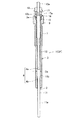
まず、本発明のグロープラグ通電制御装置101で通電制御されるグロープラグ1について説明する。図2は、グロープラグ1の断面図を示す。また、図3は、グロープラグ1をディーゼルエンジンのエンジンブロックEBに設置した状態等を示す。このグロープラグ1は、抵抗発熱ヒータとして構成されたシーズヒータ2と、その外側に配置された主体金具3とを備える。シーズヒータ2は、図3に示すように、先端が閉じたシーズチューブ11の内側に、複数の、本実施形態においては2つの抵抗線コイル、即ち、先端側に配置された発熱コイル21と、その後端に直列接続された制御コイル23とを有し、絶縁材料としてのマグネシア粉末27と共に封入されている。図2に示すように、シーズチューブ11の、発熱コイル21及び制御コイル23を収容している本体部11aは、先端側が主体金具3から突出している。図3に示すように、発熱コイル21は、その先端においてシーズチューブ11と導通しているが、発熱コイル21及び制御コイル23の外周とシーズチューブ11の内周面とは、マグネシア粉末27の介在により絶縁された状態となっている。
【0046】
このうち、発熱コイル21は、例えば、20℃での電気比抵抗R20が80μΩ・cm以上200μΩ・cm以下、1000℃での電気比抵抗をR1000として、R1000/R20が0.8以上3以下の材料、具体的には、Fe−Cr合金、あるいは、Ni−Cr合金等により構成されている。一方、制御コイル23は、例えば、20℃での電気比抵抗R20が5μΩ・cm以上20μΩ・cm以下、1000℃での電気比抵抗をR1000として、R1000/R20が6以上20以下の材料、具体的には、Ni、Co−Fe合金、あるいは、Co−Ni−Fe合金等により構成されている。
【0047】
シーズチューブ11には、その基端側から棒状の通電端子軸13が挿入され、その先端が制御コイル23の後端に溶接等により接続されている。他方、図2に示すように、通電端子軸13の後端部には、雄ねじ部13aが形成されている。また、主体金具3は、軸方向の貫通孔4を有する筒状に形成され、ここに、シーズヒータ2が、一方の開口端からシーズチューブ11の先端側を所定長突出させた状態で挿入され固定されている。この主体金具3の外周面には、グロープラグ1をディーゼルエンジンに取り付けるに際して、トルクレンチ等の工具を係合させるための六角断面形状の工具係合部9が形成されており、これに続く形で取付用のねじ部7が形成されている。
【0048】
主体金具3の貫通孔4は、シーズチューブ11が突出する開口側に位置する大径部4bと、これに続く小径部4aとを備え、この小径部4aにシーズチューブ11の基端側に形成された大径部11bが圧入され、固定されている。他方、貫通孔4の反対側の開口部には座ぐり部3aが形成され、ここに、通電端子軸13に外装されたゴム製のOリング15と絶縁ブッシュ16(例えばナイロン製のもの)とがはめ込まれている。そして、そのさらに後方側において通電端子軸13には、絶縁ブッシュ16の脱落を防止するための押さえリング17が装着されている。この押さえリング17は、外周面に形成された加締め部17aにより通電端子軸13に固定されると共に、通電端子軸13に対応する表面には、加締め結合力を高めるためのローレット部13bが形成されている。なお、19は、通電用のケーブルを通電端子軸13に固定するためのナットである。
【0049】
図3に示すように、グロープラグ1は、主体金具3のねじ部7によりディーゼルエンジン等のエンジンブロックEBのプラグホールに取り付けられている。シーズヒータ2の先端部はエンジン燃焼室CR内に一定長突出している。制御コイル23は、そのほぼ全体がエンジン燃焼室CR内に位置している。また、発熱コイル21は、制御コイル23の先端側に直列接続されているので、その全体がエンジン燃焼室CR内に位置している。
【0050】
エンジン燃焼室CRの内面から突出する制御コイル23の突出長hは、3mm以上確保されている。なお、この突出長hは、一般的に10mm以下に設定される。本明細書では、燃焼室CRの内面のプラグホール開口周縁の3次元的な幾何学的重心位置を起点として、そこからのコイル中心軸線の突出長で突出長hを定義する。但し、プラグホール開口側がテーパ面や座ぐりによる拡径部とされている場合は、その拡径部開始底の周縁を、プラグホール開口周縁と定義する。また、制御コイル23の全体がプラグホールの外にある場合には、制御コイル23の全長が突出長hである。
【0051】
制御コイル23を、上記のように、エンジン燃焼室CRの内面から突出させる取付形態を採用することにより、どのような効果を得られるかを検証した実験結果を以下に説明する。まず、各コイル21,23の詳細について以下に示す(各コイル21,23の寸法を示す記号については、図3(a),(b)を参照。)。
(発熱コイル21)
材質:鉄−クロム合金(組成:Al=7.5重量%;Cr=26重量%;Fe=残部)。
寸法:コイル太さk=0.3mm、コイル中心軸線長さCL1=2mm、コイル外径d1=2mm、ピッチP=0.8mm、R20=0.25Ω、R1000/R20=1。
(制御コイル23)
材質:コバルト−ニッケル−鉄合金(組成:Ni=25重量%;Fe=4重量%;Co=残部)。
寸法:コイル太さk=0.22mm、コイル中心軸線長さCL2=3mm、コイル外径d1=2mm、ピッチP=0.8mm、R20=0.1Ω、R1000/R20=9。
(コイル間ギャプ25)
JL:2mm。
(シーズチューブ11)
材質:SUS310S。
寸法:本体部11aの外径D1=3.5mm、肉厚t=0.5mm、本体部11aの内面から発熱コイル21(または制御コイル23)外面までの距離CG=0.25mm。
【0052】
この試験品を、炭素鋼製のブロックに形成した試験用プラグホールに装着した。制御コイル23のブロック面(燃焼室内面に相当)からの突出長(図3のhに相当)は、実施例が3mm、比較例が0mmである。そして、シーズヒータ2のブロック面からの突出部を無風状態、及び、送風機により4m/s(弱風)、あるいは、6m/s(強風)で送風しながら、後述する始動後グローステップにおいて、通電抵抗値の目標値を種々に定めてPWM方式により通電し、電流と電圧の値からシーズヒータ2の通電抵抗値を、また、シーズチューブ11の表面に接触させた熱電対により飽和温度を測定した。
【0053】
その結果、実施例では、無風、弱風及び強風のいずれの場合でも、通電抵抗値に応じて、シーズヒータ2の飽和温度が一義的に決まっている。これは、燃焼ガス等による冷却の影響を受けても制御コイル23の抵抗値変化が速やかに追従し安定な抵抗制御が実現していることを意味している。
他方、比較例では、無風、弱風及び強風の各場合により、通電抵抗値と飽和温度との関係がみな異なる傾向を示し、通電抵抗値が同じでもシーズヒータ2の飽和温度が必ずしも同一になっていない。これは、制御コイル23の全体がブロック内の没入しているために、冷却の影響が制御コイル23に及びにくく、制御コイル23の抵抗値が追従変化しなかったためであると考えられる。
【0054】
次に、本発明のグロープラグ通電制御装置101について説明する。
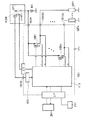
図1は、本発明のグロープラグ通電制御装置101の電気的構成を示すブロック図である。
主制御部111は、電源回路103を介して、信号処理のための安定した動作電圧を受電する。また、電源回路103は、バッテリBTからキースイッチKSW及び端子101Bを介して受電する。従って、キースイッチKSWをオン位置及びスタート位置にすると、電源回路103に電力が供給され、主制御部111が動作する。一方、キースイッチKSWをOFFにすると、電源回路103への電力供給が途絶え、主制御部111は動作を停止する。
【0055】
また、バッテリBTの電力は、端子101Fを介して、n個存在するスイッチング素子1051〜105nにそれぞれ供給されている。各スイッチング素子1051〜105nは、本実施例ではFETから構成され、バッテリBTの電圧は、FETのドレインに供給される。各FETのソースは、各端子101G1〜101Gnを介して、複数(n個)のグロープラグGP1〜GPnに接続されている。また、各FETのゲートには、主制御部111からのスイッチング信号が入力され、各グロープラグGP1〜GPnへの通電がON/OFFされる。また、各スイッチング素子1051〜105nを構成するFETは、本実施例では電流検知機能付きFET(Infineon Technologies AG 社製 PROFET(登録商標))から構成されており、これらから主制御部111へ電流信号が出力される。
【0056】
主制御部111には、バッテリBTから各グロープラグGP1〜GPnへの印加電圧、各グロープラグGP1〜GPnへの通電電流が入力される。主制御部111に入力されたグロープラグGP1〜GPnへの印加電圧とグロープラグGP1〜GPnへの通電電流の大きさは、図示しないA/Dコンバータによりデジタル化される。
また、主制御部111は、インターフェースを介して、マイクロコンピュータにより構成されたエンジン制御ユニット201(Engine Control Unit:以下、ECUとも言う。)と通信可能とされている。また、主制御部111は、オルタネータ211の駆動信号を入力可能に構成されている。
【0057】
次いで、このグロープラグ通電制御装置101によるグロープラグ1の通電制御について、図4〜図10に示したフローチャートを参照しつつ説明する。
この通電制御では、基本的に、以下の動作を行う。即ち、操作者がキースイッチKSWをオン位置にすると、プリグロー手段により制御されるプリグローステップに入る。即ち、バッテリBTの電圧をグロープラグ1に直接印加して、シーズヒータ2を短時間で昇温させて第1目標温度(例えば1000℃)まで到達させる。その後、遷移グロー手段により制御される遷移グローステップに移行する。即ち、グロープラグ1の印加電圧に基づいて、グロープラグ1への通電をPWM制御して、シーズヒータ2の温度の落ち込みを抑制する。この遷移グローステップ中に、操作者がキースイッチKSWをスタート位置にすると、今度はクランキンググロー手段により制御されるクランキンググローステップに移行する。即ち、グロープラグ1の印加電圧に基づいて、グロープラグ1への通電をPWM制御して、シーズヒータ2の温度の落ち込みを抑制し、エンジンの始動性を向上させる。エンジン始動後は、始動後グロー手段により制御される始動後グローステップに移行して、シーズヒータ2の温度を所定時間(例えば180秒間)制御し、その温度を第2目標温度(例えば900℃)とし、これを維持する。
【0058】
図4に示すように、キースイッチKSWをオン位置にすると、主制御部111に電源が投入され、具体的には、バッテリBTから、キースイッチKSW、端子101B、電源回路103を介して、主制御部111に駆動電圧が印加され、主制御部111が所定の手順で作動し始める。そして、まず、ステップS1において、主制御部111のプログラムの初期化を行う。例えば、グロープラグ1への積算電力量GwはGw=0とされる。また、プリグロー中フラグ(プリグローステップ中であることを意味するフラグ)がセットされる。一方、プリグロー終了フラグ(プリグローステップが終了したことを意味するフラグ)、スタート信号フラグ(キースイッチKSWがスタート位置とされたことを意味するフラグ)、始動後グロー中フラグ(始動後グローステップ中であることを意味するフラグ)は、それぞれクリアされる。
【0059】
次に、ステップS2において、バッテリBTからグロープラグ1に印加される電圧値と、各スイッチング素子1051〜105nを通じてグロープラグ1に流れる電流値を取り込む。そして、これらの電圧値と電流値より、各シーズヒータ2の現在の抵抗値Rを算出する。
【0060】
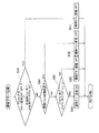
次に、ステップS3において、スタート信号の入力処理を行う。即ち、図5に示すスタート信号入力処理のサブルーチンに進む。具体的には、まず、ステップS31において、プリグローステップが終了し、かつ、始動後グローステップ中でないことを判断する。即ち、プリグロー終了フラグがセットされ、かつ、始動後グロー中フラグがクリアされているかを判断する。ここで、YES、即ち、プリグローステップが終了し、かつ、始動後グローステップ中でない場合には、ステップS32に進む。つまり、遷移グローステップ中あるいはクランキンググローステップ中の場合に、ステップS32に進む。一方、NO、即ち、プリグローステップが終了していないか、あるいは、始動後グローステップ中の場合には、そのままメインルーチンに戻る。つまり、プリグローステップ中あるいは始動後グローステップ中の場合に、そのままメインルーチンに戻る。
【0061】
ステップS32に進んだ場合には、まず、スタート信号を取り込む。そして、ステップS33に進み、スタート信号の入力が0.1sec連続してオンか否か、具体的には、スタート信号の入力が8周期連続してオンか否かを判断する。即ち、キースイッチKSWがスタート位置とされているか否かを判断する。0.1sec連続して入力をみるのは、ノイズ等による誤ったスタート信号が入力されている場合を排除するためである。ここで、YES、即ち、スタート信号の入力が0.1sec連続してオンの場合(キースイッチKSWがスタート位置とされている場合)には、ステップS34に進み、スタート信号フラグをセットする。そして、メインルーチンに戻る。一方、NO、即ち、スタート信号の入力が0.1sec連続してオンでない場合(キースイッチKSWがスタート位置とされていない場合)には、ステップS35に進む。ステップS35では、スタート信号入力が0.1sec連続してオフか否か、具体的には、スタート信号の入力が8周期連続してオフか否かを判断する。即ち、キースイッチKSWがスタート位置にないかどうかを判断する。ここで、YES、即ち、スタート信号入力が0.1sec連続してオフの場合(キースイッチKSWがスタート位置とされていない場合)には、ステップS36に進み、スタート信号フラグをクリアにする。一方、NO、即ち、スタート信号入力が0.1sec連続してオフでない場合には、そのままメインルーチンに戻る。
【0062】
次に、図4のメインルーチンのステップS5において、遷移グローステップ中に参照するデューティ比Dhと、クランキンググローステップ中に参照するデューティ比Dkをそれぞれ算出する。具体的には、遷移グローステップに関しては、グロープラグ1に印加される電圧値に基づいて、グロープラグ1に印加する電圧波形のデューティ比Dhを算出する。例えば、グロープラグ1に印加される電圧値とデューティ比Dhとの関係を示すテーブルまたは関数の形で用意しておき、これを参照してデューティ比Dhを決定するようにすればよい。同様に、クランキンググローステップに関しても、グロープラグ1に印加される電圧値に基づいて、グロープラグ1に印加する電圧波形のデューティ比Dkを算出する。例えば、グロープラグ1に印加される電圧値とデューティ比Dkとの関係を示すテーブルまたは関数の形で用意しておき、これを参照してデューティ比Dhを決定するようにすればよい。
なお、クランキンググローステップ中に参照されるデューティ比Dkは、遷移グローステップ中におけるグロープラグ1に印加される電圧値が、クランキンググローステップ中におけるグロープラグ1に印加される電圧値と同一であると仮定したときに、遷移グローステップで参照される仮想デューティ比Dhhよりも大きい。
【0063】
次に、ステップS6において、始動後グローステップ中に参照されるデューティ比Daを計算する。即ち、図6に示すサブルーチンに進む。ここでは、まず、ステップS61において、シーズヒータ2の抵抗値の誤差ΔRの計算を行う。具体的には、シーズヒータ2の現在の抵抗値をR、シーズヒータ2が第2目標温度となったときの抵抗値をRtとし、抵抗値の誤差ΔRを、ΔR=Rt−Rで与える。次に、ステップS62に進み、制御実効電圧値Vcを計算する。具体的には、制御実効電圧値Vcを、Vc=K0+K1ΔR+K2∫ΔRdtで与える。なお、K0、K1、K2は定数であるが、K0、K1、K2>0である。続いて、ステップS63に進み、デューティ比Daを計算する。具体的には、デューティ比Daを、Da=Vc2/Vb2 に従って算出する。なお、Vbは、ステップS2で取り込んだ電圧値(グロー電圧)である。そして、メインルーチンに戻る。
【0064】
次に、図4のメインルーチンのステップS7において、クランキング中か否かを判断する。即ち、スタート信号フラグがセットされているか否かを判断する。ここで、YES、即ち、クランキング中である場合(スタート信号入力フラグがセットされている場合)には、ステップS8に進む。一方、NO、即ち、クランキング中でない場合(スタート信号入力フラグがクリアされている場合)には、ステップS10に進む。
【0065】
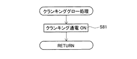
ステップS8に進んだ場合には、クランキンググロー処理を行う。即ち、図7に示すサブルーチンに進む。ここでは、ステップS81において、クランキング通電をオンにする。即ち、ステップS5で算出したデューティ比Dkに基づいて、グロープラグ1への通電をPWM制御する。その後、メインルーチンに戻る。
【0066】
次に、図4のメインルーチンでステップS7からステップS10に進んだ場合には、オルタネータが発動中か否かを判断する。
ここで、YES、即ち、オルタネータが発動中である場合には、ステップS11の始動後グロー処理に進む。即ち、図8に示すサブルーチンに進む。ここでは、まず、ステップS111において、始動後グローステップの所定時間(例えば180秒間)が経過したか否かを判断する。具体的には、後述するステップS112においてカウントアップするカウンタが所定値となったか否かで判断する。ここで、NO、即ち、始動後グロー時間が経過していない場合には、ステップS112に進む。そして、ステップS112において、始動後グロー通電をオンとし、始動後グロー中フラグをセットする。また、上記のように始動後グロー時間をカウントアップする。始動後グロー通電は、ステップS6で算出したデューティ比Daに基づいて、グロープラグ1への通電をPWM制御して、シーズヒータ2の温度がまだ第2目標温度になっていない場合には、この温度が第2目標温度となるようにし、あるいは、既に第2目標温度をなっている場合には、この温度を維持するものである。その後は、メインルーチンに戻り、ステップS9に進む。一方、ステップS111において、YES、即ち、始動後グロー時間が経過した場合には、ステップS113に進む。そして、ステップS113において、始動後グロー通電をオフとし、始動後グロー中フラグをクリアする。その後はメインルーチンに戻り、ステップS9に進む。
【0067】
次に、ステップS10において、NO、即ち、オルタネータが発動中でない場合について説明すると、この場合には、ステップS12のプリグロー処理に進む。即ち、図9に示すサブルーチンに進む。ここでは、まず、ステップS121において、プリグローステップ中であるか否かを判断する。即ち、プリグロー中フラグがセットされているかどうかを判断する。ここで、YES、即ち、プリグローステップ中である場合(プリグロー中フラグがセットされている場合)には、ステップS122に進み、1サイクルの期間中にグロープラグ1に投入された電力量(Gw1)を計算する。次に、ステップS123に進み、グロープラグ1の積算電力量(Gw)を算出する。即ち、以前の積算電力量Gwに新たに投入された電力量Gw1を加算して、新たな積算電力量Gwとする。
【0068】
次に、ステップS124において、この積算電力量Gwが、第1目標温度に対応する目標投入量を越えたか否かを判断する。ここで、NO、即ち、積算電力量Gwが目標投入量を超えていない場合には、ステップS126に進み、プリグロー通電をオンとする。具体的には、グロープラグ1へ連続通電を行う。その後、メインルーチンに戻る。一方、ステップS124において、YES、即ち、積算電力量Gwが目標投入量を超えた場合には、ステップS125に進み、プリグロー通電をオフとする。また、プリグロー中フラグをクリアし、一方でプリグロー終了フラグをセットする。その後、メインルーチンに戻る。
なお、ステップS121の判断において、NO、即ち、プリグローステップ中ではないと判断された場合(プリグロー中フラグがセットされていない場合)には、そのままメインルーチンに戻り、ステップS9に進む。
【0069】
次に、メインルーチンのステップS9では、遷移グロー処理を行う。即ち、図10に示すサブルーチンに進む。ここでは、まず、ステップS91において、クランキングステップ中か否か、あるいは、始動後グローステップ中か否かを判断する。即ち、スタート信号フラグがセットされているか、あるいは、始動後グロー中フラグがセットされているかを判断する。ここで、YES、即ち、クランキング中である場合(スタート信号フラグがセットされている場合)、あるいは、始動後グローステップ中である場合(始動後グロー中フラグがセットされている場合)には、ステップS97に進み、遷移グロー通電をオフとする。そして、メインルーチンに戻る。
【0070】
一方、ステップS91において、NO、即ち、クランキング中でなく(スタート信号フラグがクリアされており)、かつ、始動後グロー中でもない(始動後グロー中フラグもクリアされている)場合には、ステップS92に進む。ステップS92では、遷移グロー時間(遷移グローステップの所定時間)が経過したか否かを判断する。具体的には、後述するステップS94でカウントアップするカウンタが所定値となったか否かを判断する。ここで、YES、即ち、遷移グロー時間が経過している場合には、ステップS96に進み、遷移グロー通電をオフとする。そしてその後、メインルーチンに戻る。一方、ステップS92において、NO、即ち、遷移グロー時間が経過していない場合には、ステップS93に進み、プリグローステップが終了したか否かを判断する。即ち、プリグロー終了フラグがセットされているかどうかを判断する。ここで、NO、即ち、プリグローステップが終了していない場合(プリグロー終了フラグがクリアされている場合)には、ステップS95に進み、遷移グロー通電をオフとする。そしてその後、メインルーチンに戻る。これに対し、ステップS93において、プリグローステップが終了している場合(プリグロー終了フラグがセットされている場合)には、ステップS94に進み、遷移グロー通電をオンとする。この遷移グロー通電は、ステップS5で算出されたデューティ比Dhに基づいて、グロープラグ1への通電をPWM制御して、シーズヒータ2の温度の落ち込みを抑制する。また、ステップ94では、前述したように、遷移グロー時間をカウントアップする。その後、メインルーチンに戻る。
【0071】
ステップS9を経た後は、ステップS13に進む。そして、ステップS13において、12.5msが経過したか否かを判断する。ここで、YES、即ち、12.5msが経過した場合には、ステップS2に返る。一方、NO、即ち、12.5msが経過していない場合には、経過するまでステップS13を繰り返す。
本発明のグロープラグ通電制御装置101は、以上で述べた通電制御を行う。
【0072】
(実施例)
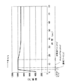
次に、具体的な実施例について説明する。本実施例では、操作者がキースイッチKSWをオン位置とした後、しばらくしてから、即ち、シーズヒータ2が十分に加熱されてから、キースイッチKSWをスタート位置とする場合のグロープラグ通電制御装置101の通電制御について説明する。図11は、本発明のグロープラグ通電制御装置101を使用したときのグロープラグ1の温度変化についてに示す。なお、本実施例においては、400℃以下の温度は測定不能であったため、400℃以上における温度変化について示してある。本実施例では、グロープラグ1を、前述したようにして、炭素鋼製のブロックに形成した試験用プラグホールに装着し、シーズヒータ2のうち、発熱コイル21の外側に位置する部分に熱電対を接触させて、シーズヒータ2の温度を測定した。この机上実験では、プリグローステップ及び遷移グローステップおいては無風状態とし、クランキンググローステップ及び始動後グローステップおいては送風機により6m/s(強風)で送風した。
【0073】
まず、操作者がキースイッチKSWをオン位置とすると、プリグローステップに入り、プリグロー手段によるグロープラグ1への通電制御により、シーズヒータ2が第1目標温度(本実施例では1000℃)までほぼ直線的に上昇する(図11参照)。
前述のフローチャートに沿って説明すると、キースイッチKSWがオン位置とされると、ステップS1に進み、グロープラグ通電制御装置101が初期化され、プリグロー中フラグがセットされ、プリグロー終了フラグ、スタート信号フラグ及び始動後グロー中フラグがクリアされる(図4参照)。続いて、ステップS2に進むが、この段階ではまだグロープラグ1に通電されていないので、抵抗値Rは算出されない。次に、ステップS3のサブルーチンに進む(図5参照)。ステップS31では、現在プリグロー中であって(プリグロー中フラグがセットされていて)、プリグローステップがまだ終了していないため(プリグロー終了フラグがセットされていないため)、NOと判断される。従って、そのままメインルーチンに戻る。次に、ステップS5に進むが、この段階ではまだグロープラグ1に通電されていないので、遷移グローステップにおけるデューティ比Dhとクランキンググローステップにおけるデューティ比Dkは算出されない。次に、ステップS6のサブルーチンに進むが、この段階ではまだグロープラグ1に通電されていないので、その抵抗値Rを求めることはできない(図6参照)。従って、始動後グローステップにおけるデューティ比Daは計算されない。次に、ステップS7に進む(図4参照)。ステップS7では、クランキング中でないので(スタート信号入力フラグがセットされていないので)、NOと判断され、ステップS10に進む。
【0074】
ステップS10では、オルタネータは発動していないので、NOと判断され、ステップS12のサブルーチンに進む(図9参照)。ステップS121では、プリグローステップ中であるので(プリグロー中フラグがセットされているので)、YESと判断され、ステップS122に進む。ステップS122では、この段階ではまだグロープラグ1への通電が行われていなめ、電力量GW1=0とされる。そして、ステップS123に進む。ステップS123では、積算電力量Gwの初期値が0であり、また、投入された電力量Gw1も0であるため、Gw=0とされる。続いて、ステップS124では、積算電力Gwが目標投入量に達していないため、NOと判断され、ステップS126に進む。そして、ステップS126において、プリグロー通電がオンとされる。即ち、バッテリBTからグロープラグ1へ連続通電が行われる。その後、メインルーチンに戻る。
【0075】
次に、ステップS9のサブルーチンに進む(図10参照)。そして、ステップS91において、クランキング中でもなく(スタート信号フラグがセットされておらず)、始動後グロー中でもないので(アフタグロー中フラグもセットされていないので)、NOと判断され、ステップS92に進む。ステップS92では、まだ遷移グローステップがされておらず、遷移グロー時間が経過していないので、NOと判断され、ステップS93に進む。ステップS93では、現在プリグローステップ中であって、まだプリグローステップが終了していないので(プリグロー終了フラグがセットされていないので)、NOと判断され、ステップS95に進む。ステップS95では、遷移グロー通電がオフとされる。その後、メインルーチンに戻り、ステップS13に進む(図4参照)。そして、12.5ms経過した後に、ステップS2に返る。
【0076】
次に、ステップS2において、グロープラグ1に印加される電圧値とグロープラグ1に流れる電流値が取り込まれ、シーズヒータ2の現在の抵抗値Rが計算される。続いて、ステップS3に進むが、上記と同様、ステップS31を経てメインルーチンに戻る(図5参照)。次に、ステップS5において、上述したように、遷移グローステップにおけるデューティ比Dhとクランキンググローステップにおけるデューティ比Dkが計算されるが、このプリグローステップ中では、これらのデューティ比Dh,Dkは使用されない(図4参照)。次に、ステップS6のサブルーチンに進み、ステップS61〜ステップS63を経て、始動後グローステップにおけるデューティ比Daが計算される(図6参照)。但し、プリグローステップ中には、このデューティ比Daは使用されない。次に、ステップS7に進む(図4参照)。ステップS7では、上記のように、クランキング中でないので、NOと判断され、ステップS10に進む。
【0077】
ステップS10では、オルタネータは発動していないので、NOと判断され、ステップS12のサブルーチンに進む(図9参照)。ステップS121では、上記のように、プリグローステップ中であるので、YESと判断され、ステップS122に進む。ステップS122では、1サイクルの期間中にグロープラグ1に投入された電力量GW1を計算する。続いて、ステップS123に進む。ステップS123で、積算電力量Gwを計算する。即ち、1サイクル前の積算電力量Gw(ここでは0)に、新たに投入された電力量Gw1を加算し、新たな積算電力量Gwとする。次に、ステップS124において、積算電力量Gwがまだ目標投入量に達していないため、NOと判断され、ステップS126に進む。そして、ステップS126において、引き続きプリグロー通電がオンとされる。その後、メインルーチンに戻る。
【0078】
次に、ステップS9のサブルーチンに進む(図10参照)。ステップS91においては、プリグローステップ中であるので、上記のように、NOと判断され、ステップS92に進む。ステップS92では、遷移グロー時間が経過していないので、NOと判断され、ステップS93に進む。ステップS93では、まだプリグローステップが終了していないので、NOと判断され、ステップS95に進む。そして、引き続き遷移グロー通電がオフとされる。その後、メインルーチンに戻り、ステップS13に進む。そして、12.5ms経過した後に、ステップS2に返る。
【0079】
その後は、積算電力量Gwが目標投入量を超えるまで(図9のステップS124参照)、しばらくの間上記のサイクルを繰り返す。そして、積算電力量Gwが目標投入量を超えた場合には、ステップS124でYESと判断され、ステップS125に進み、プリグロー通電がオフされる。また、プリグロー中フラグがクリアされ、一方でプリグロー終了フラグがセットされる。このとき、シーズヒータ2の温度は、図11に示すように、第1目標温度(1000℃)に到達している。その後、メインルーチンに戻り、ステップS9のサブルーチンに進む(図10参照)。ステップS91においては、上記と同様、クランキング中でも始動後グロー中でもないので、NOと判断され、ステップS92に進む。ステップS92では、まだ遷移グロー時間が経過していないので、NOと判断され、ステップS93に進む。そして、ステップS93においては、上記と異なり、プリグローステップが終了しているので(プリグロー終了フラグがセットされているので)、YESと判断され、ステップS94に進む。
【0080】
そして、ステップS94において、遷移グロー通電がオンとされる。即ち、ここで、プリグローステップから遷移グローステップに移行する。この遷移グローステップでは、図11に示すように、このステップ中、シーズヒータ2を第1目標温度(1000℃)に維持し、温度の落ち込みを防止する。この遷移グロー通電は、前述したように、デューティ比Dhに基づいてグロープラグ1へPWM通電される。その後、メインルーチンに戻り、ステップS13に進む(図4参照)。そして、12.5ms経過した後に、ステップS2に返る。
【0081】
次に、ステップS2において、上記のように、電圧値と電流値が取り込まれ、グロープラグ1の抵抗値Rが計算される。続いて、ステップS3のサブルーチンに進む(図5参照)。ステップS31では、プリグローステップが終了し(プリグロー終了フラグがセットされ)、かつ、始動後グローステップ中でもないので(始動後グロー中フラグがクリアされているので)、上記とは異なり、YESと判断され、ステップS32に進む。そして、ステップS32でスタート信号を取り込んだ後、ステップS33に進むが、この段階でまだ操作者がキースイッチKSWをスタート位置にしていなければ、連続したスタート信号入力はないので、NOと判断される。そして、ステップS35に進む。ステップS35では、スタート信号入力が8周期連続してオフとされていないため、NOと判断される。なお、スタート信号フラグは、ステップS1にてクリアされているので、そのクリア状態が維持される。その後、メインルーチンに戻り、ステップS5に進む(図4参照)。そして、遷移グローステップにおけるデューティ比Dhとクランキングステップにおけるデューティ比Dkが計算される。次に、ステップS6のサブルーチンに進み、始動後グローステップにおけるデューティ比Daが計算される(図6参照)。但し、遷移グローステップ中には、このデューティ比Daは使用されない。
【0082】
次に、ステップS7に進み、クランキング中でないので、NOと判断され、ステップS10に進む(図4参照)。ステップS10では、オルタネータは発動していないので、NOと判断され、ステップS12のサブルーチンに進む(図9参照)。ステップS121では、既にプリグローステップを終了しているので(プリグロー中フラグがクリアされているので)、上記とは異なり、NOと判断され、そのままメインルーチンに戻り、ステップS9のサブルーチンに進む(図10参照)。ステップS91において、上記のように、クランキング中でも始動後グロー中でもないので、NOと判断され、ステップS92に進む。ステップS92では、所定の遷移グロー時間(本実施例では30秒)が経過していないので、NOと判断され、ステップS93に進む。ステップS93では、上記のように、プリグローステップが終了しているので、YESと判断され、ステップS94に進む。そして、ステップS94において、引き続き遷移グロー通電がオンとされる。その後、メインルーチンに戻り、ステップS13に進む(図4参照)。そして、12.5ms経過した後に、ステップS2に返る。
【0083】
その後は、キースイッチKSWが連続して0.1秒間スタート位置とされるか(図5のステップS33参照)、あるいは、所定の遷移グロー時間が経過するまで(図10のステップS92参照)、上記のサイクルを繰り返す。
キースイッチKSWが連続して0.1秒間スタート位置とされないまま所定の遷移グロー時間が経過した場合には、図10に示すサブルーチンのステップS92において、YESと判断され、ステップS96に進む。そして、ステップS96において、遷移グロー通電がオフされる。即ち、遷移グローステップが終了する。その後、メインルーチンに戻り、ステップS13に進み(図4参照)、12.5ms経過した後に、ステップS2に返る。
【0084】
一方、遷移グロー時間が経過する前に、キースイッチKSWが0.1秒間連続してスタート位置とされた場合には、ステップS3のサブルーチン(図5参照)のステップS33において、連続したスタート信号入力が認められるので、YESと判断される。そして、ステップS34に進み、スタート信号フラグがセットされる。即ち、ここで、遷移グローステップからクランキンググローステップに移行する。つまり、クランキングの期間中、シーズヒータ2を第1目標温度(1000℃)に維持するように、グロープラグ1への通電をPWM制御する。その結果、図11に示すように、送風が行われているにも拘わらず、シーズヒータ2の温度に落ち込みはなく、第1目標温度(1000℃)に維持される。
【0085】
次に、ステップS5において、遷移グローステップにおけるデューティ比Dhとクランキングステップにおけるデューティ比Dkが、それぞれバッテリBTからグロープラグ1に印加される電圧値に基づいて計算される。次に、ステップS6のサブルーチンに進み(図6参照)、始動後グローステップにおけるデューティ比Daが計算される。但し、クランキンググローステップ中には、このデューティ比Daは参照されない。次に、ステップS7に進む(図4参照)。ステップS7では、上記と異なり、この段階ではスタート信号フラグがセットされているので、クランキング中とみなされ、YESと判断される。そして、ステップS8のサブルーチンに進む(図7参照)。そして、ステップS81において、クランキング通電がオンとされる。このクランキング通電は、前述したように、デューティ比Dkに基づいてグロープラグ1へPWM通電される。その後は、メインルーチンに戻り、ステップS9のサブルーチンに進む(図10参照)。ステップS91では、上記とは異なり、クランキング中であるので(スタート信号フラグがセットされているので)、YESと判断され、ステップS97に進む。そして、ステップS97において、遷移グロー通電はオフとされる。その後、メインルーチンに戻り、ステップS13に進む(図4参照)。そして、12.5ms経過した後に、ステップS2に返る。
【0086】
次に、ステップS2において、上記のように、電圧値と電流値が取り込まれ、グロープラグ1の抵抗値Rが計算される。続いて、ステップS3のサブルーチンに進む(図5参照)。ステップS31では、上記のように、プリグローステップが終了し、かつ、始動後グローステップ中でもないので、YESと判断され、ステップS32に進む。ステップS32では、連続したスタート信号入力が認められるので、YESと判断される。そして、ステップS33に進み、引き続きスタート信号フラグがセットされる。その後は、クランキングが終了し、エンジンが始動してオルタネータが発動するまで(図4のステップS10参照)、上述のサイクルが繰り返される。
【0087】
エンジンが始動した場合には、操作者はキースイッチKSWをスタート位置からオン位置に戻すので、ステップS3のサブルーチンのステップS32において、0.1秒間連続したスタート信号入力が認められなければ、NOと判断され(図5参照)、ステップS34にてYESと判断される。次に、ステップS35に進み、スタート信号フラグがクリアされる。即ち、ここで、クランキンググローステップから始動後グローステップに移行する。つまり、シーズヒータ2を第2目標温度(本実施例では900℃)とし、これを維持するように、グロープラグ1への通電をPWM制御する。その結果、図11に示すように、シースヒータ2の温度は、第1目標温度(1000℃)から徐々に低下し、第2目標温度(900℃)となった後はこの温度を維持する。
【0088】
次に、ステップS5において、遷移グローステップにおけるデューティ比Dhとクランキンググローステップにおけるデューティ比Dkがそれぞれ計算されるが、始動後グローステップ中には、これらのデューティ比Dh,Dkは参照されない(図4参照)。次に、ステップS6のサブルーチンに進む(図6参照)。そして、前述したように、ステップS61〜ステップS63を経て、始動後グローステップにおけるデューティ比Daが計算される。次に、ステップS7に進み、クランキング中でなく、スタート信号入力フラグが既にクリアされているので、NOと判断され、ステップS10に進む(図4参照)。ステップS10では、エンジンの始動によりオルタネータが発動しているので、YESと判断され、ステップS11のサブルーチンに進む(図8参照)。ステップS111では、まだ始動後グローステップの所定時間(本実施例では180秒)が経過していないため、NOと判断され、ステップS112に進む。そして、ステップS112において、始動後グロー通電がオンとされる。また、始動後グロー中フラグがセットされる。始動後グロー通電は、前述したように、シーズヒータ2の温度がまだ第2目標温度(900℃)となっていない場合には、第2目標温度となるようにグロープラグ1への通電をPWM制御し、既に第2目標温度となっている場合には、この温度を維持するようにグロープラグ1への通電をPWM制御する。その後、メインルーチンに戻り、ステップS9のサブルーチンに進む(図10参照)。ステップS91において、アフタグロー中フラグがセットされ、始動後グロー中であるので、YESと判断され、ステップS97に進む。そして、遷移グロー通電がオフとされる。その後、メインルーチンに戻り、ステップS13に進み(図4参照)、12.5ms経過した後に、ステップS2に返る。
そして、ステップS2において、上記のように、電圧値と電流値が取り込まれ、グロープラグ1の抵抗値Rが計算される。
【0089】
その後は、始動後グロー時間が経過するまで(図8のステップS111参照)、上記のサイクルが繰り返される。始動後グロー時間が経過すると、ステップS11のサブルーチンのステップS111において、YESと判断され、ステップS113に進む。そして、ステップS113において、始動後グロー通電がオフとされる。また、始動後グロー中フラグがクリアされる。これにより、始動後グローステップが終了する。即ち、本発明のグロープラグ通電制御装置101によるグロープラグ1への通電制御が終了する。
【0090】
以上で説明したように、本実施形態では、グロープラグ通電制御装置101は、4つの手段、即ち、プリグロー手段と遷移グロー手段とクランキンググロー手段と始動後グロー手段とを備える。
このうち、プリグロー手段は、キースイッチKSWがオン位置とされたときに、シーズヒータ2の温度が急速昇温するように、グロープラグ1への通電を制御するものである。このような手段を持つことにより、キースイッチKSWがオン位置とされたときに、他の手段よりも、平均電力を大きく設定してグロープラグ1への通電を行うことができる。従って、シーズヒータ2の温度を効率よく昇温させることができる。
【0091】
遷移グロー手段は、プリグロー手段による通電制御に続いて、バッテリBTからグロープラグ1に印加される電圧値に基づいて、グロープラグ1に印加する電圧波形のデューティ比Dhを算出し、このデューティ比Dhによりグロープラグ1への通電をPWM制御するものである。このような手段を持つことにより、プリグロー手段による通電制御後にシーズヒータ2からその周囲への熱引きが生じることをも見込んで、グロープラグ1への通電を制御することができる。しかも、PWM制御は、デューテイ比Dhによりグロープラグへの投入電力を簡単に調整できる利点がある。従って、シーズヒータ2の温度の落ち込みを防止し、エンジンの始動性を向上させることができる。
【0092】
クランキンググロー手段は、遷移グロー手段による通電制御中に、キースイッチKSWがスタート位置とされエンジンのクランキングが開始されたときに、クランキングの期間中、バッテリBTからグロープラグ1に印加される電圧値に基づいて、グロープラグ1に印加する電圧波形のデューティ比Dkを算出するものである。また、この手段は、遷移グロー手段による制御期間におけるバッテリBTの電圧値が、この手段による制御期間におけるバッテリBTの電圧値と同一であると仮定したときに、遷移グロー手段で算出される仮想デューティ比Dhhよりも大きいデューティ比Dkにより、グロープラグ1への通電をPWM制御するものである。このような手段を持つことにより、クランキング期間中に起こるシーズヒータ2の温度低下をも見込んで、グロープラグ1への通電を制御することができる。しかも、PWM制御は、デューテイ比Dkによりグロープラグ1への投入電力を簡単に調整できる利点がある。従って、クランキング期間中であっても、シーズヒータ2の温度の落ち込みを防止し、エンジンの始動性を向上させることができる。
【0093】
始動後グロー手段は、エンジンの始動後、プリグロー手段によりグロープラグ1へ供給する電力よりも小さい電力をグロープラグ1へ供給し、シーズヒータ2の安定加熱を図るものである。このような手段により、エンジン始動後もシーズヒータ2の温度を安定に加熱できるので、エンジンの燃焼室内の暖気を促進させ、また、ディーゼルノックの発生を防止し、騒音や白煙の発生、HC成分の排出などを抑制することができる。
【0094】
さらに、本実施形態のプリグロー手段は、グロープラグ1への積算電力量が第1目標温度に対応する所定値となるまで、グロープラグ1への通電を制御する。このように積算電力量で制御すれば、シーズヒータ2の温度をより正確に第1目標温度まで上昇させることできるため、シーズヒータ2の予熱不足や予熱過剰を効果的に抑制することができる。
【0095】
またさらに、本実施形態のプリグロー手段は、グロープラグ1へ連続通電を行う。このように連続通電をすることで、より効率よく短時間で、シーズヒータ2の温度を第1目標温度に向けて昇温させることができる。
またさらに、本実施形態の遷移グロー手段は、これによる通電制御が開始されてから所定時間内にキースイッチKSWがスタート位置とされないときには、グロープラグ1への通電を停止する。これにより、グロープラグ1やバッテリBTに掛かる負担を軽減し、これらを保護することができる。
【0096】
またさらに、本実施形態の始動後グロー手段は、シーズヒータ2の温度が第2目標温度となり、これを維持するように、グロープラグ1への通電を制御する。これにより、エンジン始動後もシーズヒータ2の温度を第2目標温度とし、これを維持できるので、より効果的に、エンジンの燃焼室内の暖気を促進させ、また、ディーゼルノックの発生を防止し、騒音や白煙の発生、HC成分の排出などを抑制することができる。
またさらに、本実施形態の始動後グロー手段は、シーズヒータ2の抵抗値に基づいて、グロープラグ1に印加する電圧波形のデューティ比Daを算出し、これによりグロープラグ1への通電をPWM制御する。PWM制御は、デューテイ比によりグロープラグへの投入電力を簡単に調整できる利点がある。ここで、始動後グロー手段による制御期間中は、燃焼噴霧やスワールなどの外的な要因により、シーズヒータ2の温度が低下することがあるため、これを見込んでシーズヒータ2を安定加熱する必要がある。一方、始動後グロー手段による制御期間中におけるシーズヒータ2の抵抗値は、その温度に対応した定常状態にあるので、即ち、シーズヒータ2の抵抗値とその温度との間で相関があるので、その抵抗値に基づいて算出したデューティ比Daを利用すれば、ヒータ温度をより正確に第2目標温度とし、これを安定に維持することができる。
【0097】
またさらに、本実施形態の始動後グロー手段は、シーズヒータ2の抵抗値の誤差ΔRを、ΔR=Rt−Rで与え、制御実効電圧値Vcを、Vc=K0+K1ΔR+K2∫ΔRdtで与えたとき、デューティ比Daを、Da=Vc2/Vb2 に従って算出する算出手段を有する。このようにしてデューティ比Daを算出し、グロープラグ1への通電を制御すれば、始動後グロー手段による制御中のシーズヒータ2の温度をより正確に第2目標温度とし、これをより安定に維持することができる。
またさらに、本実施形態では、プリグロー手段による制御中にキースイッチがスタート位置とされエンジンのクランキングが開始されたときには、プリグロー手段による制御終了を待ってから、クランキンググロー手段による制御に移行させるプリグロー優先手段を備える。このため、プリグロー手段による制御が終了し、シーズヒータ2が十分に昇温してから、クランキンググロー手段による制御がなされるので、エンジンを短時間で確実に始動させることができる。
【0098】
以上において、本発明を実施形態及び実施例に即して説明したが、本発明は上述の実施形態に限定されるものではなく、その要旨を逸脱しない範囲で、適宜変更して適用できることはいうまでもない。
【図面の簡単な説明】
【図1】実施形態に係るグロープラグ通電制御装置を示す回路図である。
【図2】実施形態に係り、使用するグロープラグの断面図である。
【図3】実施形態に係り、グロープラグをエンジンに取り付けた状態を示す部分断面図である。
【図4】実施形態に係るグロープラグ通電制御装置による通電制御を示すフローチャートである。
【図5】実施形態に係るグロープラグ通電制御装置による通電制御のうち、スタート信号入力処理について示すフローチャートである。
【図6】実施形態に係るグロープラグ通電制御装置による通電制御のうち、始動後グロー中のデューティ比Da計算について示すフローチャートである。
【図7】実施形態に係るグロープラグ通電制御装置による通電制御のうち、クランキンググロー処理について示すフローチャートである。
【図8】実施形態に係るグロープラグ通電制御装置による通電制御のうち、始動後グロー処理について示すフローチャートである。
【図9】実施形態に係るグロープラグ通電制御装置による通電制御のうち、プリグロー処理について示すフローチャートである。
【図10】実施形態に係るグロープラグ通電制御装置による通電制御のうち、遷移グロー処理について示すフローチャートである。
【図11】実施例に関し、キーをオン位置にしてからの時間とグロープラグの温度との関係について示すグラフである。
【符号の説明】
1 グロープラグ
2 シーズヒータ(抵抗発熱ヒータ)
101 グロープラグ通電制御装置
111 主制御部
KSW キースイッチ
BT バッテリ
EB エンジンブロック[0001]
TECHNICAL FIELD OF THE INVENTION
The present invention relates to a glow plug energization control device and a glow plug energization control method for controlling energization of a glow plug that assists in starting an internal combustion engine.
[0002]
[Prior art]
The glow plug generally uses a resistance heating heater. This glow plug is configured by attaching a resistance heating heater to a metal shell, and is used by being attached to an engine block of a diesel engine such that the tip of the resistance heating heater is located in the combustion chamber.
A glow plug energization control device is known as a device for controlling the energization of such a glow plug. In the conventional glow plug energization control device, when the key switch is turned to the ON position, the temperature of the resistance heating heater is increased toward a first target temperature (for example, 1000 ° C.) sufficient to start the engine. The power supply to the glow plug is controlled to supply a large amount of power to the glow plug. Such a step is generally called a pre-glow or a pre-glow step. In a glow plug capable of rapid heating, the temperature of the resistance heating heater can be raised to the first target temperature within several seconds. Next, after the temperature of the resistance heating heater reaches the first target temperature, the glow is maintained so that the temperature of the resistance heating heater maintains the second target temperature (for example, 900 ° C.) for a predetermined period (for example, 180 seconds). By controlling energization of the plug, a small amount of power is supplied to the glow plug. Such a step is generally called an afterglow or an afterglow step. Before starting the engine, maintain the temperature of the resistance heating heater at a sufficiently high temperature so that the engine can be started at any time, and after starting the engine, promote warm air in the combustion chamber of the engine and reduce the generation of diesel knock. It is possible to prevent noise, generate white smoke, and discharge HC components.
Documents related to such technology include, for example,
[0003]
[Patent Document 1]
JP-A-56-129763
[Patent Document 2]
JP-A-60-67775
[0004]
[Problems to be solved by the invention]
However, in the conventional glow plug energizing device, a phenomenon was observed in which the temperature of the resistance heating heater temporarily dropped below the second target temperature to be maintained immediately after the transition from the pre-glow step to the after-glow step. This is because even when the temperature of the resistance heating heater reaches the first target temperature in the pre-glow step, the temperature around the resistance heating heater such as the engine block and the metal shell is low, and these have not yet reached a steady state. This is considered to be due to the fact that the temperature of the resistance heating heater is largely deprived of these. In this state where the temperature of the resistance heater is lowered, the engine is difficult to start even if cranking is started with the key switch as a start position.
[0005]
When the key switch is set to the start position during the after-glow step and cranking of the engine is started, also in this case, the phenomenon that the temperature of the resistance heating heater falls below the second target temperature to be maintained. Was seen. This is presumably due to the fact that the resistance heating heater is cooled by an external factor such as combustion spray or swirl. Secondly, it is considered that during cranking, excessive power is required for cranking, and the voltage of the battery is significantly reduced. In particular, immediately after shifting to the after-glow step, since the heat is drawn from the resistance heating heater to its surroundings as described above, there has been a problem that the temperature of the resistance heating heater is remarkably reduced and the startability of the engine is poor. .
[0006]
The present invention has been made in view of such circumstances, and a glow plug control device and a glow plug that can prevent the temperature of a resistance heating heater from dropping after completion of a pre-glow step and improve startability of an engine. It is an object to provide an energization control method.
[0007]
Means for Solving the Problems, Functions and Effects
The glow plug energization control device controls the energization from a battery to a glow plug having a resistance heating heater installed in an engine when a key switch is set to an ON position and a start position. When the switch is set to the ON position, a pre-glow means for controlling energization of the glow plug so that the temperature of the resistance heating heater rapidly increases, and after the energization control by the pre-glow means, the battery A transition glow means for calculating a duty ratio Dh of a voltage waveform applied to the glow plug on the basis of a voltage value applied to the glow plug, and performing PWM control on energization to the glow plug with the duty ratio Dh; During the energization control by the transition glow means, the key switch is set to the start position and the When cranking of the gin is started, a duty cycle Dk of a voltage waveform applied to the glow plug is calculated based on a voltage value applied to the glow plug from the battery during the cranking period. A ranking glow means, wherein assuming that the battery voltage value during the control period by the transition glow means is the same as the battery voltage value during the control period by the cranking glow means, With the duty ratio Dk larger than the virtual duty ratio Dhh calculated by the above, cranking glow means for performing PWM control of energization to the glow plug, and electric power supplied to the glow plug by the pre-glow means after the start of the engine. Also supplies a small amount of power to the glow plug, And post-start glow means to stabilize the heating heat heater, a glow plug energization control apparatus comprising a.
[0008]
According to the present invention, the glow plug energization control device includes four means, namely, a pre-glow means, a transition glow means, a cranking glow means, and a post-start glow means.
Among them, the pre-glow means controls the power supply to the glow plug so that the temperature of the resistance heating heater rapidly rises when the key switch is turned on. By having such a means, when the key switch is turned to the ON position, it is possible to set the average power to be larger than that of the other means and to energize the glow plug. Therefore, the temperature of the resistance heater can be efficiently increased. The pre-glow means may be a means for continuously energizing the glow plug for a predetermined time irrespective of the battery voltage, or a glow plug until the integrated power amount supplied to the glow plug reaches a predetermined value corresponding to the first target temperature, as described later. Some power supply to plug. In any case, the temperature of the resistance heating heater is raised to or near the first target temperature by the control by the pre-glow means.
[0009]
The transition glow means calculates the duty ratio Dh of the voltage waveform applied to the glow plug based on the voltage value applied from the battery to the glow plug, following the energization control by the pre-glow means. PWM control of the power supply to the power supply. As described above, conventionally, there has been a problem that the temperature of the resistance heating heater temporarily drops due to the heat removal from the resistance heating heater to the surroundings immediately after the transition from the pre-glow step to the after-glow step. On the other hand, in the present invention, a transition glow unit is separately provided, and the energization to the glow plug is PWM-controlled. That is, after the energization control by the pre-glow means, the energization to the glow plug is controlled in view of the fact that heat is drawn from the resistance heating heater to the surroundings. In addition, the PWM control has an advantage that the input power to the glow plug can be easily adjusted by the duty ratio Dh. Therefore, it is possible to prevent the temperature of the resistance heating heater from dropping and to improve the startability of the engine. In addition, if the duty ratio Dh according to each receiving voltage is determined in advance, the control mode can be simplified.
[0010]
During the energization control by the transition glow means, the cranking glow means sets the voltage value applied from the battery to the glow plug during the cranking period when the key switch is set to the start position and cranking of the engine is started. Based on this, the duty ratio Dk of the voltage waveform applied to the glow plug is calculated. Also, this means may be such that the virtual duty ratio Dhh calculated by the transition glow means when the battery voltage value during the control period by the transition glow means is the same as the battery voltage value during the control period by this means. The energization of the glow plug is PWM-controlled with a duty ratio Dk larger than that. As described above, in the conventional energization control device, during the cranking, the temperature of the resistance heating heater is controlled during the control period by the transition glow means due to an external factor such as combustion spray or swirl or a decrease in the battery voltage due to the cranking. There was a problem that it fell further than that. On the other hand, in the present invention, a cranking glow unit is separately provided, and the energization to the glow plug is PWM-controlled. That is, the power supply to the glow plug is controlled in consideration of the temperature drop of the resistance heating heater that occurs during the cranking period. Specifically, the duty ratio Dk calculated by the cranking glow means is made larger than the virtual duty ratio Dhh calculated when the control is performed by the transition glow means, and the energization to the glow plug is controlled. . In addition, the PWM control has an advantage that the input power to the glow plug can be easily adjusted by the duty ratio Dk. Therefore, even during the cranking period, it is possible to prevent the temperature of the resistance heating heater from dropping and to improve the startability of the engine. If the duty ratio Dk according to each receiving voltage is determined in advance, the control mode can be simplified.
[0011]
The post-start glow means supplies a smaller amount of electric power to the glow plug than the electric power supplied to the glow plug by the pre-glow means after the start of the engine, thereby stably heating the resistance heating heater. By such means, the temperature of the resistance heating heater can be stably heated even after the engine is started, so that warm air in the combustion chamber of the engine is promoted, diesel knock is prevented from being generated, noise and white smoke are generated, HC is generated. Emission of components can be suppressed.
[0012]
Further, in the glow plug energization control device, the pre-glow means controls energization to the glow plug until the integrated power amount supplied to the glow plug reaches a predetermined value corresponding to a first target temperature. A glow plug energization control device may be used.
[0013]
As the control by the pre-glow means, it is conceivable to raise the temperature of the resistance heating heater to the first target temperature by energizing the glow plug for a predetermined time set in advance. However, since the battery voltage is not always constant, insufficient preheating or excessive preheating of the resistance heating heater is likely to occur. Insufficient preheating affects the startability of the engine. On the other hand, in the case of excessive preheating, defects such as shortened service life of the resistance heating heater, disconnection, and melting are likely to occur. On the other hand, the pre-glow means of the present invention controls the energization of the glow plug until the integrated power amount to the glow plug reaches a predetermined value corresponding to the first target temperature. If the control is performed using the integrated power amount in this manner, the temperature of the resistance heating heater can be more accurately raised to the first target temperature, and therefore, insufficient preheating or excessive preheating of the resistance heating heater can be effectively suppressed.
[0014]
Further, in the glow plug energization control device according to any of the above, the pre-glow means may be a glow plug energization control device that continuously energizes the glow plug during the control period.
[0015]
According to the present invention, the pre-glow means continuously supplies current to the glow plug. By performing the continuous energization in this manner, the temperature of the resistance heating heater can be more efficiently and quickly raised to the first target temperature in a short time.
[0016]
Further, in the glow plug energization control device according to any one of the above, the transition glow means may be configured such that the key switch is not set to the start position within a predetermined time after the energization control by the transition glow means is started. The glow plug energization control device may be configured to stop energization of the glow plug.
[0017]
According to the present invention, the transition glow unit stops energizing the glow plug when the key switch is not set to the start position within a predetermined time after the energizing control is started. If the energization control by the long-time transition glow means is continued, the load on the glow plug increases, and the battery tends to run out. On the other hand, if a long time has elapsed since the key switch was turned on, it is considered that the operator has no intention to start the engine. Therefore, the glow plug and the battery can be protected by stopping the current supply to the glow plug after the lapse of a predetermined time as in the present invention.
[0018]
Further, in the glow plug energization control device according to any one of the above, the post-start glow means may control the glow plug so that the temperature of the resistance heating heater reaches a second target temperature and maintains the second target temperature. It is preferable to use a glow plug energization control device that controls energization.
[0019]
According to the present invention, the after-start glow means controls the energization of the glow plug so that the temperature of the resistance heater becomes the second target temperature and maintains the second target temperature. As a result, the temperature of the resistance heater can be maintained at the second target temperature even after the engine is started, and this can be maintained. Therefore, the warm air in the combustion chamber of the engine can be more effectively promoted, and the occurrence of diesel knock can be prevented. Generation of noise and white smoke, emission of HC components, and the like can be suppressed.
[0020]
Further, in the glow plug energization control device, the post-start glow means calculates a duty ratio Da of a voltage waveform applied to the glow plug based on a resistance value of the resistance heating heater, It is preferable to use a glow plug energization control device that performs PWM control on energization of the glow plug based on Da.
[0021]
According to the present invention, the post-start glow means calculates the duty ratio Da of the voltage waveform applied to the glow plug based on the resistance value of the resistance heater, and thereby controls the energization of the glow plug by PWM. The PWM control has an advantage that the power supplied to the glow plug can be easily adjusted by the duty ratio. Here, during the control period by the glow means after the start, since the temperature of the resistance heating heater may decrease due to external factors such as combustion spray and swirl, it is necessary to anticipate this and stably heat the resistance heating heater. There is. On the other hand, the resistance value of the resistance heating heater during the control period by the glow means after the start is in a steady state corresponding to the temperature, that is, since there is a correlation between the resistance value of the resistance heating heater and the temperature, If the duty ratio Da calculated based on the resistance value is used, it is possible to more accurately set the heater temperature to the second target temperature and stably maintain the second target temperature. If the duty ratio Da corresponding to each resistance value is determined in advance, the heater temperature can be controlled by a simple control mode.
[0022]
Further, in the glow plug energization control device, the post-start glow means may set a current resistance value of the glow plug to R, and a resistance value when the temperature of the resistance heating heater reaches the second target temperature. Is Rt, the applied voltage to the glow plug is Vb, the error ΔR is given by ΔR = Rt−R, and the control effective voltage value Vc is given by Vc = K 0 + K 1 ΔR + K 2 When given by ∫ΔRdt, the duty ratio Da is given by: Da = Vc 2 / Vb 2 It is preferable to use a glow plug energization control device having a calculating means for calculating according to the following.
[0023]
According to the present invention, the post-start glow means gives the error ΔR of the resistance value of the resistance heating heater by ΔR = Rt−R, and sets the control effective voltage value Vc to Vc = K 0 + K 1 ΔR + K 2 When given by ∫ΔRdt, the duty ratio Da is given by: Da = Vc 2 / Vb 2 Calculation means for calculating according to the following. If the duty ratio Da is calculated in this way and the energization of the glow plug is controlled, the temperature of the resistance heating heater being controlled by the glow means after starting is more accurately set as the second target temperature, and is maintained more stably. can do. Note that K 0 , K 1 , K 2 Indicates a coefficient.
[0024]
Furthermore, in the glow plug energization control device according to any one of the above, when the key switch is set to the start position and cranking of the engine is started during energization control by the pre-glow means, the pre-glow means It is preferable that the glow plug energization control device includes a pre-glow priority unit that shifts to energization control by the cranking glow unit after the energization control ends.
[0025]
If the energization control by the cranking glow unit is started during the energization control by the pre-glow unit, the voltage applied to the glow plug decreases with a decrease in the battery voltage, so that the resistance heating heater is not sufficiently heated, and the engine is started. May be reduced. On the other hand, in the present invention, when the key switch is set to the start position and the cranking of the engine is started during the energization control by the pre-glow means, the energization control by the cranking glow means is waited until the end of the energization control by the pre-glow means. And a pre-glow priority means for shifting to. For this reason, the energization control by the pre-glow means is terminated, and the energization control by the cranking glow means is performed after the temperature of the resistance heating heater is sufficiently raised, so that the engine can be started reliably.
[0026]
Another solution is a glow plug energization control method for controlling energization from a battery to a glow plug having a resistance heating heater installed in an engine when a key switch is set to an ON position and a start position. A pre-glow step of controlling energization of the glow plug so that the temperature of the resistance heating heater rapidly rises when the key switch is set to the on position; and A transition glow step of calculating a duty ratio Dh of a voltage waveform applied to the glow plug from the battery based on a voltage value applied to the glow plug, and performing PWM control on energization of the glow plug with the duty ratio Dh. During the transition glow step, the key switch is set to the start position and the engine When cranking is started, a cranking glow for calculating a duty ratio Dk of a voltage waveform applied to the glow plug based on a voltage value applied to the glow plug from the battery during the cranking period. A virtual duty ratio Dhh calculated in the transition glow step, assuming that the battery voltage value in the transition glow step is the same as the battery voltage value in the cranking glow step. A cranking glow step of performing PWM control on energization of the glow plug with a duty ratio Dk that is larger than that of the glow plug, and a power smaller than the power supplied to the glow plug in the pre-glow step after the start of the engine. To the heater, And after starting glow step to reduce the heating, a glow plug energization control method comprising a.
[0027]
The glow plug energization control method of the present invention includes four steps, namely, a pre-glow step, a transition glow step, a cranking glow step, and a post-start glow step.
Among them, in the pre-glow step, the power supply to the glow plug is controlled so that the temperature of the resistance heating heater rapidly rises when the key switch is turned on. By having such a step, when the key switch is turned to the ON position, it is possible to set the average power to be larger than in the other steps and to energize the glow plug. Therefore, the temperature of the resistance heater can be efficiently increased.
[0028]
In the transition glow step, following the pre-glow step, the duty ratio Dh of the voltage waveform applied to the glow plug is calculated based on the voltage value applied from the battery to the glow plug. The energization is PWM controlled. As described above, conventionally, there has been a problem that the temperature of the resistance heating heater temporarily drops due to the heat removal from the resistance heating heater to the surroundings immediately after the transition from the pre-glow step to the after-glow step. On the other hand, in the present invention, a transition glow step is separately provided, and the energization to the glow plug is PWM-controlled. That is, energization of the glow plug is controlled in consideration of the fact that heat is drawn from the resistance heating heater to the surroundings after the pre-glow step. In addition, the PWM control has an advantage that the input power to the glow plug can be easily adjusted by the duty ratio Dh. Therefore, it is possible to prevent the temperature of the resistance heating heater from dropping and to improve the startability of the engine.
[0029]
In the cranking glow step, during the transition glow step, when the key switch is set to the start position and the cranking of the engine is started, based on the voltage value applied from the battery to the glow plug during the cranking period, The duty ratio Dk of the voltage waveform applied to the glow plug is calculated. Further, in this step, assuming that the battery voltage value in the transition glow step is the same as the battery voltage value in this step, the duty ratio Dk that is larger than the virtual duty ratio Dhh calculated in the transition glow step Thereby, the power supply to the glow plug is PWM controlled. As described above, conventionally, during the cranking, there is a problem that the temperature of the resistance heating heater drops further than during the transition glow step due to an external factor such as combustion spray or swirl or a decrease in the battery voltage due to the cranking. there were. On the other hand, in the present invention, a cranking glow step is separately provided, and energization to the glow plug is PWM-controlled. That is, the power supply to the glow plug is controlled in consideration of the temperature drop of the resistance heating heater that occurs during the cranking period. Specifically, the duty ratio Dk calculated in the cranking glow step is made larger than the virtual duty ratio Dhh calculated in the case where the control is performed in the transition glow step, and the energization to the glow plug is controlled. . In addition, the PWM control has an advantage that the input power to the glow plug can be easily adjusted by the duty ratio Dk. Therefore, even during the cranking period, it is possible to prevent the temperature of the resistance heating heater from dropping and to improve the startability of the engine.
[0030]
In the post-start glow step, after the engine is started, electric power smaller than the electric power supplied to the glow plug in the pre-glow step is supplied to the glow plug to stably heat the resistance heater. By such a step, the temperature of the resistance heating heater can be stably heated even after the engine is started, so that warm air in the combustion chamber of the engine is promoted, diesel knock is prevented from being generated, noise and white smoke are generated, HC is generated. Emission of components can be suppressed.
[0031]
Further, in the above glow plug energization control method, in the pre-glow step, energization to the glow plug is controlled until the integrated power amount to the glow plug reaches a predetermined value corresponding to a first target temperature. A glow plug energization control method may be used.
[0032]
As the energization control in the pre-glow step, it is conceivable to raise the temperature of the resistance heating heater to the first target temperature by energizing the glow plug for a predetermined time set in advance. However, as described above, since the battery voltage is not always constant, insufficient preheating or excessive preheating of the resistance heating heater is likely to occur. On the other hand, in the pre-glow step of the present invention, energization of the glow plug is controlled until the integrated power amount to the glow plug reaches a predetermined value corresponding to the first target temperature. If the control is performed using the integrated power amount in this manner, the temperature of the resistance heating heater can be more accurately raised to the first target temperature, and therefore, insufficient preheating or excessive preheating of the resistance heating heater can be effectively suppressed.
[0033]
Further, in the glow plug energization control method according to any of the above, in the pre-glow step, a glow plug energization control method for continuously energizing the glow plug may be used.
[0034]
According to the present invention, in the pre-glow step, the glow plug is continuously energized. By performing the continuous energization in this manner, the temperature of the resistance heating heater can be more efficiently and quickly raised to the first target temperature in a short time.
[0035]
Furthermore, in the glow plug energization control method according to any one of the above, in the transition glow step, when the key switch is not set to the start position within a predetermined time after the transition glow step is started, the glow plug is turned on. It is preferable to use a glow plug energization control method in which energization of the plug is stopped.
[0036]
According to the present invention, in the transition glow step, the power supply to the glow plug is stopped when the key switch is not set to the start position within a predetermined time after the start of this step. If the energization control in the long-time transition glow step is continued, the load on the glow plug increases, and the battery tends to run out. On the other hand, if a long time has elapsed since the key switch was turned on, it is considered that the operator has no intention to start the engine. Therefore, the glow plug and the battery can be protected by stopping the current supply to the glow plug after the lapse of a predetermined time as in the present invention.
[0037]
Further, in the glow plug energization control method according to any one of the above, in the after-start glow step, the temperature of the resistance heating heater becomes a second target temperature, and the glow plug is controlled to maintain the second target temperature. A glow plug energization control method for controlling energization may be used.
[0038]
According to the present invention, in the post-start glow step, after the engine is started, the temperature of the resistance heater becomes the second target temperature, and the energization to the glow plug is controlled so as to maintain the second target temperature. By such a step, the temperature of the resistance heating heater can be set to the second target temperature even after the engine is started, and can be maintained at the second target temperature. It is possible to prevent noise, generate white smoke, and discharge HC components.
[0039]
Further, in the glow plug energization control method according to any one of the above, in the after-start glow step, a duty ratio Da of a voltage waveform applied to the glow plug is calculated based on a resistance value of the resistance heater. A glow plug energization control method may be used in which energization to the glow plug is PWM-controlled based on the duty ratio Da.
[0040]
According to the present invention, in the post-start glow step, the duty ratio Da of the voltage waveform applied to the glow plug is calculated based on the resistance value of the resistance heating heater, and thereby the energization to the glow plug is PWM-controlled. The PWM control has an advantage that the power supplied to the glow plug can be easily adjusted by the duty ratio. Here, during the glow step after the start, the temperature of the resistance heating heater may decrease due to external factors such as combustion spray and swirl. Therefore, it is necessary to stably heat the resistance heating heater in anticipation of this. On the other hand, the resistance value of the resistance heating heater during the glow step after starting is in a steady state corresponding to the temperature, that is, since there is a correlation between the resistance value of the resistance heating heater and the temperature, the resistance value By using the duty ratio Da calculated based on the above, it is possible to more accurately set the heater temperature to the second target temperature and to stably maintain the second target temperature.
[0041]
Further, in the above glow plug energization control method, in the after-start glow step, the current resistance value of the glow plug is R, and the resistance value when the resistance heating heater reaches the second target temperature is Rt. The voltage applied to the glow plug is Vb, the error ΔR is given by ΔR = Rt−R, and the control effective voltage value Vc is given by Vc = K 0 + K 1 ΔR + K 2 When given by ∫ΔRdt, the duty ratio Da is given by: Da = Vc 2 / Vb 2 It is preferable to adopt a glow plug energization control method having a calculation step of calculating according to the following.
[0042]
According to the present invention, in the post-start glow step, the error ΔR of the resistance value of the resistance heating heater is given by ΔR = Rt−R, and the control effective voltage value Vc is given by Vc = K 0 + K 1 ΔR + K 2 When given by ∫ΔRdt, the duty ratio Da is given by: Da = Vc 2 / Vb 2 In accordance with the following. By calculating the duty ratio Da in this way and controlling the energization of the glow plug, the temperature of the resistance heating heater during the glow step after starting can be more accurately set to the second target temperature and maintained more stably. Can be. Note that K 0 , K 1 , K 2 Indicates a coefficient.
[0043]
Further, in the glow plug energization control method according to any of the above, when the key switch is set to the start position and cranking of the engine is started during the pre-glow step, the pre-glow step ends. It is preferable to use a glow plug energization control method that shifts to the cranking glow step after waiting.
[0044]
If the energization control by the cranking glow step is started during the pre-glow step, the voltage applied to the glow plug decreases with a decrease in the battery voltage. descend. On the other hand, in the present invention, when the key switch is set to the start position and the cranking of the engine is started during the pre-glow step, the process is shifted to the cranking glow step after the pre-glow step is completed. For this reason, the cranking glow step is performed after the pre-glow step is completed and the temperature of the resistance heating heater is sufficiently raised, so that the engine can be reliably started.
[0045]
BEST MODE FOR CARRYING OUT THE INVENTION
Hereinafter, embodiments of the present invention will be described with reference to the drawings.
First, the
[0046]
Among them, the
[0047]
A rod-shaped current-carrying
[0048]
The through
[0049]
As shown in FIG. 3, the
[0050]
The projecting length h of the
[0051]
An experimental result of verifying what effect can be obtained by adopting the mounting configuration in which the
(Heating coil 21)
Material: iron-chromium alloy (composition: Al = 7.5% by weight; Cr = 26% by weight; Fe = remainder).
Dimensions: coil thickness k = 0.3 mm, coil center axis length CL1 = 2 mm, coil outer diameter d1 = 2 mm, pitch P = 0.8 mm, R20 = 0.25Ω, R1000 / R20 = 1.
(Control coil 23)
Material: cobalt-nickel-iron alloy (composition: Ni = 25% by weight; Fe = 4% by weight; Co = remainder).
Dimensions: coil thickness k = 0.22 mm, coil center axis length CL2 = 3 mm, coil outer diameter d1 = 2 mm, pitch P = 0.8 mm, R20 = 0.1Ω, R1000 / R20 = 9.
(Gap between coils 25)
JL: 2 mm.
(Seeds tube 11)
Material: SUS310S.
Dimensions: Outer diameter D1 of
[0052]
The test article was mounted in a test plug hole formed in a carbon steel block. The protrusion length (corresponding to h in FIG. 3) of the
[0053]
As a result, in the embodiment, the saturation temperature of the sheathed
On the other hand, in the comparative example, the relationship between the energization resistance value and the saturation temperature tends to be different depending on the case of no wind, weak wind, and strong wind, and the saturation temperature of the sheathed
[0054]
Next, the glow plug
FIG. 1 is a block diagram showing an electrical configuration of a glow plug
The
[0055]
The power of the battery BT is supplied to the
[0056]
The
The
[0057]
Next, energization control of the
In this energization control, basically, the following operation is performed. That is, when the operator turns the key switch KSW to the ON position, the operation enters a pre-glow step controlled by the pre-glow means. That is, the voltage of the battery BT is directly applied to the
[0058]
As shown in FIG. 4, when the key switch KSW is turned to the ON position, the
[0059]
Next, in step S2, a voltage value applied from the battery BT to the
[0060]
Next, in step S3, input processing of a start signal is performed. That is, the process proceeds to the subroutine of the start signal input process shown in FIG. Specifically, first, in step S31, it is determined that the pre-glow step is completed and that the post-start glow step is not in progress. That is, it is determined whether the pre-glow end flag is set and the post-start glow flag is cleared. Here, if YES, that is, if the pre-glow step has been completed and the post-start glow step is not being performed, the process proceeds to step S32. In other words, when it is during the transition glow step or the cranking glow step, the process proceeds to step S32. On the other hand, if NO, that is, if the pre-glow step has not been completed or if the glow step is being performed after the start, the process returns to the main routine. That is, during the pre-glow step or the glow step after the start, the process returns to the main routine.
[0061]
When the process proceeds to step S32, first, a start signal is fetched. Then, the process proceeds to step S33, and it is determined whether or not the input of the start signal is continuously ON for 0.1 second, specifically, whether or not the input of the start signal is continuously ON for eight cycles. That is, it is determined whether or not the key switch KSW is at the start position. The reason why the input is viewed continuously for 0.1 sec is to eliminate a case where an erroneous start signal due to noise or the like is input. Here, if YES, that is, if the input of the start signal is continuously ON for 0.1 sec (the key switch KSW is at the start position), the process proceeds to step S34, and the start signal flag is set. Then, the process returns to the main routine. On the other hand, if NO, that is, if the input of the start signal is not ON continuously for 0.1 sec (the key switch KSW is not set to the start position), the process proceeds to step S35. In step S35, it is determined whether or not the input of the start signal is continuously off for 0.1 second, specifically, whether or not the input of the start signal is continuously off for eight cycles. That is, it is determined whether the key switch KSW is not at the start position. Here, if YES, that is, if the start signal input is continuously off for 0.1 sec (the key switch KSW is not set to the start position), the process proceeds to step S36 to clear the start signal flag. On the other hand, if NO, that is, if the start signal input is not off continuously for 0.1 sec, the process returns to the main routine.
[0062]
Next, in step S5 of the main routine of FIG. 4, the duty ratio Dh referred during the transition glow step and the duty ratio Dk referred during the cranking glow step are calculated. Specifically, regarding the transition glow step, the duty ratio Dh of the voltage waveform applied to the
The duty ratio Dk referred to during the cranking glow step is the same as the voltage value applied to the
[0063]
Next, in step S6, a duty ratio Da referred during the post-start glow step is calculated. That is, the process proceeds to a subroutine shown in FIG. Here, first, in step S61, the error ΔR of the resistance value of the sheathed
[0064]
Next, in step S7 of the main routine in FIG. 4, it is determined whether cranking is being performed. That is, it is determined whether or not the start signal flag is set. Here, if YES, that is, if cranking is being performed (when the start signal input flag is set), the process proceeds to step S8. On the other hand, if NO, that is, if cranking is not being performed (the start signal input flag has been cleared), the process proceeds to step S10.
[0065]
When the process proceeds to step S8, a cranking glow process is performed. That is, the process proceeds to a subroutine shown in FIG. Here, in step S81, the cranking energization is turned on. That is, the power supply to the
[0066]
Next, when the process proceeds from step S7 to step S10 in the main routine of FIG. 4, it is determined whether or not the alternator is running.
Here, if YES, that is, if the alternator is being activated, the flow proceeds to the post-start glow processing in step S11. That is, the process proceeds to a subroutine shown in FIG. Here, first, in step S111, it is determined whether or not a predetermined time (for example, 180 seconds) of the glow step after starting has elapsed. Specifically, the determination is made based on whether or not a counter that counts up in step S112 described below has reached a predetermined value. Here, if NO, that is, if the post-start glow time has not elapsed, the process proceeds to step S112. Then, in step S112, the after-start glow energization is turned on, and the after-start glow flag is set. Further, the post-start glow time is counted up as described above. In the post-start glow energization, the energization to the
[0067]
Next, a description will be given of the case where the determination in step S10 is NO, that is, the case where the alternator is not in operation. That is, the process proceeds to a subroutine shown in FIG. Here, first, in step S121, it is determined whether or not a pre-glow step is being performed. That is, it is determined whether the pre-glow flag is set. Here, if YES, that is, if the pre-glow step is being performed (the pre-glow flag is set), the process proceeds to step S122, and the amount of power (Gw1) supplied to the
[0068]
Next, in step S124, it is determined whether or not the integrated power amount Gw has exceeded a target input amount corresponding to the first target temperature. Here, if NO, that is, if the integrated power amount Gw does not exceed the target input amount, the process proceeds to step S126, and the pre-glow energization is turned on. Specifically, the
If the determination in step S121 is NO, that is, if it is determined that the pre-glow step is not being performed (the pre-glow flag is not set), the process returns to the main routine and proceeds to step S9.
[0069]
Next, in step S9 of the main routine, transition glow processing is performed. That is, the process proceeds to a subroutine shown in FIG. Here, first, in step S91, it is determined whether or not a cranking step is being performed or whether or not a post-start glowing step is being performed. That is, it is determined whether the start signal flag is set or the after-start glow flag is set. Here, if YES, that is, if cranking is being performed (start signal flag is set), or if it is during the glow step after starting (if the after-start glowing flag is set), Then, the process proceeds to step S97, where the transition glow energization is turned off. Then, the process returns to the main routine.
[0070]
On the other hand, if NO in step S91, that is, if it is not during cranking (the start signal flag is cleared) and it is not during glowing after starting (the glowing after starting flag is also cleared), step S91 is executed. Proceed to S92. In step S92, it is determined whether or not a transition glow time (a predetermined time of the transition glow step) has elapsed. Specifically, it is determined whether or not a counter that counts up in step S94 described below has reached a predetermined value. Here, if YES, that is, if the transition glow time has elapsed, the process proceeds to step S96, and the transition glow energization is turned off. Then, the process returns to the main routine. On the other hand, if NO in step S92, that is, if the transition glow time has not elapsed, the process proceeds to step S93, and it is determined whether the pre-glow step has been completed. That is, it is determined whether the pre-glow end flag is set. Here, if NO, that is, if the pre-glow step is not completed (the pre-glow end flag is cleared), the process proceeds to step S95, and the transition glow energization is turned off. Then, the process returns to the main routine. On the other hand, when the pre-glow step has been completed in step S93 (when the pre-glow end flag has been set), the process proceeds to step S94, and the transition glow energization is turned on. In the transition glow energization, the energization to the
[0071]
After step S9, the process proceeds to step S13. Then, in step S13, it is determined whether 12.5 ms has elapsed. Here, if YES, that is, if 12.5 ms has elapsed, the process returns to step S2. On the other hand, if NO, that is, if 12.5 ms has not elapsed, step S13 is repeated until the time has elapsed.
The glow plug
[0072]
(Example)
Next, specific examples will be described. In the present embodiment, the glow plug energization control in a case where the key switch KSW is set to the start position some time after the operator sets the key switch KSW to the ON position, that is, after the
[0073]
First, when the operator turns the key switch KSW to the ON position, a pre-glow step is entered, and by controlling the energization of the
When the key switch KSW is turned to the ON position, the process proceeds to step S1, the glow plug
[0074]
In step S10, since the alternator has not been activated, the determination is NO, and the process proceeds to the subroutine of step S12 (see FIG. 9). In step S121, since it is in the pre-glow step (since the pre-glow flag is set), it is determined to be YES, and the process proceeds to step S122. In step S122, power is not yet supplied to the
[0075]
Next, the process proceeds to a subroutine of step S9 (see FIG. 10). Then, in step S91, since it is not during cranking (the start signal flag is not set) and it is not glowing after starting (the after-glow flag is not set), it is determined as NO, and the process proceeds to step S92. In step S92, since the transition glow step has not been performed yet and the transition glow time has not elapsed, it is determined to be NO, and the process proceeds to step S93. In step S93, since the pre-glow step is currently in progress and the pre-glow step has not yet been completed (because the pre-glow end flag has not been set), it is determined to be NO, and the process proceeds to step S95. In step S95, the transition glow energization is turned off. Thereafter, the process returns to the main routine and proceeds to step S13 (see FIG. 4). Then, after elapse of 12.5 ms, the process returns to step S2.
[0076]
Next, in step S2, the voltage value applied to the
[0077]
In step S10, since the alternator has not been activated, the determination is NO, and the process proceeds to the subroutine of step S12 (see FIG. 9). In step S121, since the pre-glow step is being performed as described above, YES is determined, and the process proceeds to step S122. In step S122, the amount of power GW1 input to the
[0078]
Next, the process proceeds to a subroutine of step S9 (see FIG. 10). In step S91, since the pre-glow step is being performed, NO is determined as described above, and the process proceeds to step S92. In step S92, since the transition glow time has not elapsed, NO is determined, and the process proceeds to step S93. In step S93, since the pre-glow step has not been completed yet, the determination is NO, and the process proceeds to step S95. Then, the transition glow energization is turned off. Thereafter, the process returns to the main routine and proceeds to step S13. Then, after elapse of 12.5 ms, the process returns to step S2.
[0079]
Thereafter, the above cycle is repeated for a while until the integrated power amount Gw exceeds the target input amount (see step S124 in FIG. 9). If the integrated power amount Gw exceeds the target input amount, YES is determined in step S124, the process proceeds to step S125, and the pre-glow energization is turned off. Also, the pre-glow flag is cleared, while the pre-glow end flag is set. At this time, the temperature of the
[0080]
Then, in step S94, the transition glow energization is turned on. That is, here, the process shifts from the pre-glow step to the transition glow step. In this transition glow step, as shown in FIG. 11, during this step, the sheathed
[0081]
Next, in step S2, the voltage value and the current value are taken in as described above, and the resistance value R of the
[0082]
Next, the process proceeds to step S7, in which no cranking is being performed, so that the determination is NO, and the process proceeds to step S10 (see FIG. 4). In step S10, since the alternator has not been activated, the determination is NO, and the process proceeds to the subroutine of step S12 (see FIG. 9). In step S121, since the pre-glow step has already been completed (because the pre-glow flag has been cleared), unlike the above, it is determined to be NO, the process returns to the main routine, and proceeds to the subroutine of step S9 (FIG. 10). In step S91, as described above, since neither cranking nor glowing after starting is performed, NO is determined, and the process proceeds to step S92. In step S92, since the predetermined transition glow time (30 seconds in this embodiment) has not elapsed, the determination is NO, and the process proceeds to step S93. In step S93, as described above, since the pre-glow step has been completed, YES is determined, and the process proceeds to step S94. Then, in step S94, the transition glow energization is continuously turned on. Thereafter, the process returns to the main routine and proceeds to step S13 (see FIG. 4). Then, after elapse of 12.5 ms, the process returns to step S2.
[0083]
Thereafter, the key switch KSW is continuously set to the start position for 0.1 second (see step S33 in FIG. 5) or until a predetermined transition glow time elapses (see step S92 in FIG. 10). Repeat the cycle.
When the predetermined transition glow time has elapsed without the key switch KSW being continuously set to the start position for 0.1 second, YES is determined in the step S92 of the subroutine shown in FIG. 10, and the process proceeds to the step S96. Then, in step S96, the transition glow energization is turned off. That is, the transition glow step ends. Thereafter, the process returns to the main routine, proceeds to step S13 (see FIG. 4), and after 12.5 ms has elapsed, returns to step S2.
[0084]
On the other hand, if the key switch KSW is continuously set to the start position for 0.1 second before the transition glow time elapses, a continuous start signal is input in step S33 of the subroutine of step S3 (see FIG. 5). Is recognized, it is determined to be YES. Then, the process proceeds to step S34, where a start signal flag is set. That is, here, a transition is made from the transition glow step to the cranking glow step. That is, the power supply to the
[0085]
Next, in step S5, the duty ratio Dh in the transition glow step and the duty ratio Dk in the cranking step are calculated based on the voltage value applied to the
[0086]
Next, in step S2, the voltage value and the current value are taken in as described above, and the resistance value R of the
[0087]
When the engine is started, the operator returns the key switch KSW from the start position to the ON position. Therefore, in step S32 of the subroutine of step S3, if the start signal input for 0.1 second is not recognized, NO is determined. It is determined (see FIG. 5), and YES is determined in step S34. Next, the process proceeds to step S35, where the start signal flag is cleared. That is, here, a transition is made from the cranking glow step to the post-start glow step. That is, the
[0088]
Next, in step S5, the duty ratio Dh in the transition glow step and the duty ratio Dk in the cranking glow step are calculated, but these duty ratios Dh and Dk are not referred to during the glow step after starting (see FIG. 4). Next, the process proceeds to a subroutine of step S6 (see FIG. 6). Then, as described above, through steps S61 to S63, the duty ratio Da in the post-start glow step is calculated. Next, the process proceeds to step S7, where cranking is not being performed and the start signal input flag has already been cleared, so that the determination is NO, and the process proceeds to step S10 (see FIG. 4). In step S10, since the alternator has been activated by the start of the engine, YES is determined, and the process proceeds to the subroutine of step S11 (see FIG. 8). In step S111, since the predetermined time (180 seconds in this embodiment) of the glow step after starting has not yet elapsed, the determination is NO, and the process proceeds to step S112. Then, in step S112, the after-start glow energization is turned on. Also, the post-start glow flag is set. As described above, when the temperature of the sheathed
Then, in step S2, the voltage value and the current value are acquired as described above, and the resistance value R of the
[0089]
Thereafter, the above cycle is repeated until the post-start glow time elapses (see step S111 in FIG. 8). When the glow time has elapsed after the start, YES is determined in step S111 of the subroutine of step S11, and the process proceeds to step S113. Then, in step S113, the after-start glow energization is turned off. Also, the after-start glow flag is cleared. Thus, the glow step after the start is completed. That is, the energization control of the
[0090]
As described above, in the present embodiment, the glow plug
Of these, the pre-glow means controls the energization of the
[0091]
The transition glow means calculates the duty ratio Dh of the voltage waveform applied to the
[0092]
The cranking glow means is applied from the battery BT to the
[0093]
The post-start glow means supplies the
[0094]
Further, the pre-glow means of the present embodiment controls the energization of the
[0095]
Further, the pre-glow means of the present embodiment continuously supplies current to the
Furthermore, the transition glow means of this embodiment stops energization of the
[0096]
Further, the post-start glow means of the present embodiment controls the energization of the
Further, the post-start glow means of the present embodiment calculates the duty ratio Da of the voltage waveform applied to the
[0097]
Further, the post-start glow means of the present embodiment gives the error ΔR of the resistance value of the sheathed
Further, in the present embodiment, when the key switch is set to the start position and the cranking of the engine is started during the control by the pre-glow means, the control is shifted to the control by the cranking glow means after waiting for the control end by the pre-glow means. Pre-glow priority means is provided. Therefore, the control by the cranking glow means is performed after the control by the pre-glow means is completed and the temperature of the sheathed
[0098]
In the above, the present invention has been described with reference to the embodiments and examples. However, the present invention is not limited to the above-described embodiments, and it can be said that the present invention can be appropriately modified and applied without departing from the gist thereof. Not even.
[Brief description of the drawings]
FIG. 1 is a circuit diagram showing a glow plug energization control device according to an embodiment.
FIG. 2 is a cross-sectional view of a glow plug used according to the embodiment.
FIG. 3 is a partial cross-sectional view showing a state where a glow plug is attached to an engine according to the embodiment.
FIG. 4 is a flowchart showing energization control by a glow plug energization control device according to the embodiment.
FIG. 5 is a flowchart illustrating a start signal input process in energization control by the glow plug energization control device according to the embodiment.
FIG. 6 is a flowchart showing calculation of a duty ratio Da during glow after starting, in the energization control by the glow plug energization control device according to the embodiment.
FIG. 7 is a flowchart showing cranking glow processing in the energization control by the glow plug energization control device according to the embodiment.
FIG. 8 is a flowchart showing a post-start glow process in the energization control by the glow plug energization control device according to the embodiment.
FIG. 9 is a flowchart showing a pre-glow process in the energization control by the glow plug energization control device according to the embodiment.
FIG. 10 is a flowchart showing transition glow processing in the energization control by the glow plug energization control device according to the embodiment.
FIG. 11 is a graph showing a relationship between a time after a key is turned on and a glow plug temperature in the embodiment.
[Explanation of symbols]
1 glow plug
2 Seeds heater (resistance heating heater)
101 Glow plug energization control device
111 Main control unit
KSW key switch
BT battery
EB engine block
Claims (12)
上記キースイッチが上記オン位置とされたときに、上記抵抗発熱ヒータの温度が急速昇温するように、上記グロープラグへの通電を制御するプリグロー手段と、
上記プリグロー手段による通電制御に続いて、上記バッテリから上記グロープラグに印加される電圧値に基づいて、上記グロープラグに印加する電圧波形のデューティ比Dhを算出し、このデューティ比Dhにより上記グロープラグへの通電をPWM制御する遷移グロー手段と、
上記遷移グロー手段による通電制御中に、上記キースイッチが上記スタート位置とされ上記エンジンのクランキングが開始されたときに、上記クランキングの期間中、上記バッテリから上記グロープラグに印加される電圧値に基づいて、上記グロープラグに印加する電圧波形のデューティ比Dkを算出するクランキンググロー手段であって、上記遷移グロー手段による制御期間における上記バッテリの電圧値が、このクランキンググロー手段による制御期間における上記バッテリの電圧値と同一であると仮定したときに、上記遷移グロー手段で算出される仮想デューティ比Dhhよりも大きいデューティ比Dkにより、上記グロープラグへの通電をPWM制御するクランキンググロー手段と、
上記エンジンの始動後、上記プリグロー手段により上記グロープラグへ供給する電力よりも小さい電力を上記グロープラグへ供給し、上記抵抗発熱ヒータの安定加熱を図る始動後グロー手段と、
を備えるグロープラグ通電制御装置。A glow plug energization control device that controls energization from a battery to a glow plug having a resistance heating heater installed in an engine when a key switch is set to an ON position and a start position,
Pre-glow means for controlling energization of the glow plug so that the temperature of the resistance heating heater rapidly rises when the key switch is set to the ON position;
Subsequent to the energization control by the pre-glow means, a duty ratio Dh of a voltage waveform applied to the glow plug is calculated based on a voltage value applied to the glow plug from the battery, and the glow plug is calculated based on the duty ratio Dh. Transition glow means for performing PWM control on energization of the power supply;
During the energization control by the transition glow means, when the key switch is set to the start position and cranking of the engine is started, a voltage value applied to the glow plug from the battery during the cranking period A duty ratio Dk of a voltage waveform applied to the glow plug on the basis of the above, wherein the voltage value of the battery during the control period by the transition glow unit is controlled by the control period by the cranking glow unit. The cranking glow means for performing PWM control on energization of the glow plug by a duty ratio Dk which is larger than the virtual duty ratio Dhh calculated by the transition glow means, assuming that the voltage value is the same as the battery voltage value in the above. When,
After the start of the engine, a post-start glow means for supplying a smaller electric power than the electric power supplied to the glow plug by the pre-glow means to the glow plug to stably heat the resistance heating heater,
A glow plug energization control device comprising:
前記プリグロー手段は、前記グロープラグへ投入した積算電力量が第1目標温度に対応する所定値となるまで、上記グロープラグへの通電を制御する
グロープラグ通電制御装置。The glow plug energization control device according to claim 1,
The glow plug energization control device controls the energization of the glow plug until the integrated power amount supplied to the glow plug reaches a predetermined value corresponding to a first target temperature.
前記プリグロー手段は、その制御期間中、前記グロープラグへ連続通電を行うグロープラグ通電制御装置。The glow plug energization control device according to claim 1 or 2, wherein:
A glow plug energization control device for continuously energizing the glow plug during the control period.
前記遷移グロー手段は、この遷移グロー手段による通電制御が開始されてから所定時間内に前記キースイッチが前記スタート位置とされないときには、前記グロープラグへの通電を停止する
グロープラグ通電制御装置。The glow plug energization control device according to any one of claims 1 to 3, wherein
The glow plug energization control device, wherein the transition glow means stops energization to the glow plug when the key switch is not set to the start position within a predetermined time after the energization control by the transition glow means is started.
前記始動後グロー手段は、前記抵抗発熱ヒータの温度が第2目標温度となり、これを維持するように、前記グロープラグへの通電を制御する
グロープラグ通電制御装置。The glow plug energization control device according to any one of claims 1 to 4,
The post-start glow means is a glow plug energization control device that controls energization of the glow plug so that the temperature of the resistance heating heater reaches a second target temperature and maintains the second target temperature.
前記始動後グロー手段は、前記抵抗発熱ヒータの抵抗値に基づいて、前記グロープラグに印加する電圧波形のデューティ比Daを算出し、このデューティ比Daにより上記グロープラグへの通電をPWM制御する
グロープラグ通電制御装置。The glow plug energization control device according to claim 5,
The post-start glow means calculates a duty ratio Da of a voltage waveform applied to the glow plug based on a resistance value of the resistance heating heater, and controls the energization of the glow plug by PWM based on the duty ratio Da. Plug energization control device.
上記キースイッチが上記オン位置とされたときに、上記抵抗発熱ヒータの温度が急速昇温するように、上記グロープラグへの通電を制御するプリグローステップと、
上記プリグローステップに続いて、上記バッテリから上記グロープラグに印加される電圧値に基づいて、上記グロープラグに印加する電圧波形のデューティ比Dhを算出し、このデューティ比Dhにより上記グロープラグへの通電をPWM制御する遷移グローステップと、
上記遷移グローステップ中に、上記キースイッチが上記スタート位置とされ上記エンジンのクランキングが開始されたときに、上記クランキングの期間中、上記バッテリから上記グロープラグに印加される電圧値に基づいて、上記グロープラグに印加する電圧波形のデューティ比Dkを算出するクランキンググローステップであって、上記遷移グローステップにおける上記バッテリの電圧値が、このクランキンググローステップにおける上記バッテリの電圧値と同一であると仮定したときに、上記遷移グローステップで算出される仮想デューティ比Dhhよりも大きいデューティ比Dkにより、上記グロープラグへの通電をPWM制御するクランキンググローステップと、
上記エンジンの始動後、上記プリグローステップで上記グロープラグへ供給する電力よりも小さい電力を上記グロープラグへ供給し、上記抵抗発熱ヒータの安定加熱を図る始動後グローステップと、
を備えるグロープラグ通電制御方法。A glow plug energization control method for controlling energization from a battery to a glow plug having a resistance heating heater installed in an engine when a key switch is set to an ON position and a start position,
A pre-glow step of controlling energization of the glow plug so that when the key switch is set to the ON position, the temperature of the resistance heating heater rapidly rises;
Subsequent to the pre-glow step, a duty ratio Dh of a voltage waveform applied to the glow plug is calculated based on a voltage value applied from the battery to the glow plug. A transition glow step for performing PWM control of energization;
During the transition glow step, when the key switch is set to the start position and cranking of the engine is started, during the cranking period, based on a voltage value applied to the glow plug from the battery. A cranking glow step for calculating a duty ratio Dk of a voltage waveform applied to the glow plug, wherein the voltage value of the battery in the transition glow step is the same as the voltage value of the battery in the cranking glow step. A cranking glow step of performing PWM control on energization of the glow plug with a duty ratio Dk larger than the virtual duty ratio Dhh calculated in the transition glow step,
After the start of the engine, a post-start glow step for supplying power smaller than the power supplied to the glow plug in the pre-glow step to the glow plug to stably heat the resistance heater,
A glow plug energization control method comprising:
前記プリグローステップでは、前記グロープラグへの積算電力量が第1目標温度に対応する所定値となるまで、上記グロープラグへの通電を制御する
グロープラグ通電制御方法。The glow plug energization control method according to claim 7,
In the pre-glow step, a glow plug energization control method that controls energization of the glow plug until the integrated power amount to the glow plug reaches a predetermined value corresponding to a first target temperature.
前記プリグローステップでは、前記グロープラグへ連続通電を行う
グロープラグ通電制御方法。A glow plug energization control method according to claim 7 or claim 8,
In the pre-glow step, a glow plug energization control method for continuously energizing the glow plug.
前記遷移グローステップでは、この遷移グローステップが開始されてから所定時間内に前記キースイッチが前記スタート位置とされないときには、前記グロープラグへの通電を停止する
グロープラグ通電制御方法。The glow plug energization control method according to any one of claims 7 to 9, wherein
In the transition glow step, a glow plug energization control method for stopping energization of the glow plug when the key switch is not set to the start position within a predetermined time after the start of the transition glow step.
前記始動後グローステップでは、前記抵抗発熱ヒータの温度が第2目標温度となり、これを維持するように、前記グロープラグへの通電を制御する
グロープラグ通電制御方法。The glow plug energization control method according to any one of claims 7 to 10, wherein
In the after-start glow step, the glow plug energization control method includes controlling the energization of the glow plug so that the temperature of the resistance heater reaches the second target temperature and maintains the second target temperature.
前記始動後グローステップでは、前記抵抗発熱ヒータの抵抗値に基づいて、前記グロープラグに印加する電圧波形のデューティ比Daを算出し、このデューティ比Daにより上記グロープラグへの通電をPWM制御する
グロープラグ通電制御方法。The glow plug energization control method according to claim 11, wherein
In the after-start glow step, a duty ratio Da of a voltage waveform applied to the glow plug is calculated based on a resistance value of the resistance heating heater, and a glow that PWM-controls energization to the glow plug with the duty ratio Da. Plug energization control method.
Priority Applications (4)
| Application Number | Priority Date | Filing Date | Title |
|---|---|---|---|
| JP2003019797A JP3810744B2 (en) | 2003-01-29 | 2003-01-29 | Glow plug energization control device and glow plug energization control method |
| US10/765,711 US6843218B2 (en) | 2003-01-29 | 2004-01-28 | Glow plug energization control apparatus and glow plug energization control method |
| DE602004001239T DE602004001239T2 (en) | 2003-01-29 | 2004-01-28 | Device and method for controlling the energization of a glow plug |
| EP04250439A EP1447560B1 (en) | 2003-01-29 | 2004-01-28 | Apparatus and method for controlling the energization of glow plug |
Applications Claiming Priority (1)
| Application Number | Priority Date | Filing Date | Title |
|---|---|---|---|
| JP2003019797A JP3810744B2 (en) | 2003-01-29 | 2003-01-29 | Glow plug energization control device and glow plug energization control method |
Publications (2)
| Publication Number | Publication Date |
|---|---|
| JP2004232907A true JP2004232907A (en) | 2004-08-19 |
| JP3810744B2 JP3810744B2 (en) | 2006-08-16 |
Family
ID=32677557
Family Applications (1)
| Application Number | Title | Priority Date | Filing Date |
|---|---|---|---|
| JP2003019797A Expired - Fee Related JP3810744B2 (en) | 2003-01-29 | 2003-01-29 | Glow plug energization control device and glow plug energization control method |
Country Status (4)
| Country | Link |
|---|---|
| US (1) | US6843218B2 (en) |
| EP (1) | EP1447560B1 (en) |
| JP (1) | JP3810744B2 (en) |
| DE (1) | DE602004001239T2 (en) |
Cited By (13)
| Publication number | Priority date | Publication date | Assignee | Title |
|---|---|---|---|---|
| JP2008157614A (en) * | 2006-12-21 | 2008-07-10 | Robert Bosch Gmbh | Method of controlling temperature of glow plug of internal combustion engine, computer program, recording medium, and controller for temperature of glow plug of internal combustion engine |
| US7487753B2 (en) | 2006-03-29 | 2009-02-10 | Ngk Spark Plug Co., Ltd. | Glow plug energization control apparatus and method |
| KR100916442B1 (en) | 2007-11-13 | 2009-09-07 | 기아자동차주식회사 | Preheating system for automobile |
| JP2009287496A (en) * | 2008-05-30 | 2009-12-10 | Ngk Spark Plug Co Ltd | Glow plug electrification control apparatus and glow plug electrification control system |
| JP2009287494A (en) * | 2008-05-30 | 2009-12-10 | Ngk Spark Plug Co Ltd | Glow plug electrification control apparatus and glow plug electrification control system |
| JP2010065980A (en) * | 2008-09-12 | 2010-03-25 | Ngk Spark Plug Co Ltd | Heater energization control apparatus and heater energization control method |
| JP2010520963A (en) * | 2007-03-09 | 2010-06-17 | ベル アーゲー | Glow plug energization control method |
| JP2011001840A (en) * | 2009-06-17 | 2011-01-06 | Ngk Spark Plug Co Ltd | Energization control device for glow plug |
| KR101212461B1 (en) | 2005-09-21 | 2012-12-14 | 보그와르너 베루 시스템스 게엠바흐 | Method for operating a group of glow plugs in a diesel engine |
| WO2013054598A1 (en) * | 2011-10-11 | 2013-04-18 | 株式会社デンソー | Heating device |
| KR101501043B1 (en) * | 2007-07-06 | 2015-03-18 | 보그와르너 베루 시스템스 게엠바흐 | Method of Operating glow plugs in Diesel Engines |
| JP2016020774A (en) * | 2014-07-15 | 2016-02-04 | 日本特殊陶業株式会社 | Glow plug |
| JP2020035008A (en) * | 2018-08-27 | 2020-03-05 | オムロン株式会社 | Temperature control system, temperature control method, and program |
Families Citing this family (18)
| Publication number | Priority date | Publication date | Assignee | Title |
|---|---|---|---|---|
| EP2395226B1 (en) * | 2003-07-28 | 2013-07-17 | Phillips and Temro Industries Inc. | Controller for air intake heater |
| JP4654964B2 (en) * | 2006-04-13 | 2011-03-23 | 株式会社デンソー | Glow plug energization control device |
| DE102006021285B4 (en) | 2006-05-05 | 2023-05-17 | Borgwarner Ludwigsburg Gmbh | Process for operating glow plugs in diesel engines |
| DE102006048225A1 (en) * | 2006-10-11 | 2008-04-17 | Siemens Ag | Method for determining a glow plug temperature |
| DE102006048226A1 (en) * | 2006-10-11 | 2008-04-17 | Siemens Ag | A method for detecting activation of a starting device for initializing an annealing process |
| JP2008157485A (en) * | 2006-12-21 | 2008-07-10 | Denso Corp | Glow plug |
| US20100103576A1 (en) * | 2007-03-05 | 2010-04-29 | Hitoshi Sugimoto | Glow plug driver |
| DE102007029022B4 (en) * | 2007-06-23 | 2009-05-14 | Beru Ag | Annealing system, control device and method for controlling the power of a glow plug |
| DE102007038131B3 (en) | 2007-07-06 | 2008-12-24 | Beru Ag | A method of heating a ceramic glow plug and glow plug control device |
| DE102009020148B4 (en) * | 2009-05-05 | 2011-09-01 | Beru Ag | Method for determining the heating characteristic of a glow plug |
| JP5155964B2 (en) | 2009-08-07 | 2013-03-06 | 日本特殊陶業株式会社 | Glow plug energization control device and heat generation system |
| GB2472811B (en) * | 2009-08-19 | 2017-03-01 | Gm Global Tech Operations Llc | Glowplug temperature estimation method and device |
| JP5660612B2 (en) * | 2011-01-12 | 2015-01-28 | ボッシュ株式会社 | Glow plug tip temperature estimation method and glow plug drive control device |
| EP2759771B1 (en) * | 2011-09-20 | 2017-04-26 | Bosch Corporation | Glow plug diagnostic method and glow plug drive control device |
| DE102012105376B4 (en) * | 2012-03-09 | 2015-03-05 | Borgwarner Ludwigsburg Gmbh | Method for controlling the temperature of a glow plug |
| JP6271915B2 (en) * | 2013-08-28 | 2018-01-31 | 日本特殊陶業株式会社 | Internal combustion engine equipped with glow plug with combustion pressure sensor and glow plug without sensor |
| DE102017115946A1 (en) * | 2017-07-14 | 2019-01-17 | Borgwarner Ludwigsburg Gmbh | Method for controlling the temperature of a glow plug |
| CN114675625A (en) * | 2022-03-21 | 2022-06-28 | 潍柴动力股份有限公司 | Controller control method and device |
Family Cites Families (6)
| Publication number | Priority date | Publication date | Assignee | Title |
|---|---|---|---|---|
| JPS56126674A (en) * | 1980-03-12 | 1981-10-03 | Diesel Kiki Co Ltd | Auxiliary stater of diesel engine |
| JPS56129763A (en) * | 1980-03-13 | 1981-10-12 | Ngk Spark Plug Co Ltd | Auxiliary apparatus used for starting diesel engine |
| JPS6067775A (en) | 1983-09-21 | 1985-04-18 | Mitsubishi Electric Corp | Glow plug controller |
| JP2602677B2 (en) | 1987-12-17 | 1997-04-23 | 自動車機器株式会社 | Glow plug energization control device |
| US4939347A (en) * | 1987-12-17 | 1990-07-03 | Jidosha Kiki Co., Ltd. | Energization control apparatus for glow plug |
| DE19936729C1 (en) * | 1999-08-06 | 2000-11-16 | Webasto Thermosysteme Gmbh | Glow plug control method for ignition of automobile heating device uses measured electrical resistance across glow plug for controlling clocked voltage supplied to glow plug during ignition phase |
-
2003
- 2003-01-29 JP JP2003019797A patent/JP3810744B2/en not_active Expired - Fee Related
-
2004
- 2004-01-28 DE DE602004001239T patent/DE602004001239T2/en not_active Expired - Lifetime
- 2004-01-28 US US10/765,711 patent/US6843218B2/en not_active Expired - Lifetime
- 2004-01-28 EP EP04250439A patent/EP1447560B1/en not_active Revoked
Cited By (17)
| Publication number | Priority date | Publication date | Assignee | Title |
|---|---|---|---|---|
| KR101212461B1 (en) | 2005-09-21 | 2012-12-14 | 보그와르너 베루 시스템스 게엠바흐 | Method for operating a group of glow plugs in a diesel engine |
| US7487753B2 (en) | 2006-03-29 | 2009-02-10 | Ngk Spark Plug Co., Ltd. | Glow plug energization control apparatus and method |
| JP2008157614A (en) * | 2006-12-21 | 2008-07-10 | Robert Bosch Gmbh | Method of controlling temperature of glow plug of internal combustion engine, computer program, recording medium, and controller for temperature of glow plug of internal combustion engine |
| JP2010520963A (en) * | 2007-03-09 | 2010-06-17 | ベル アーゲー | Glow plug energization control method |
| KR101501043B1 (en) * | 2007-07-06 | 2015-03-18 | 보그와르너 베루 시스템스 게엠바흐 | Method of Operating glow plugs in Diesel Engines |
| KR100916442B1 (en) | 2007-11-13 | 2009-09-07 | 기아자동차주식회사 | Preheating system for automobile |
| US8217310B2 (en) | 2008-05-30 | 2012-07-10 | Ngk Spark Plug Co., Ltd. | Glow plug electrification control apparatus and glow plug electrification control system |
| US8228659B2 (en) | 2008-05-30 | 2012-07-24 | Ngk Spark Plug Co., Ltd. | Glow plug electrification control apparatus and glow plug electrification control system |
| JP2009287494A (en) * | 2008-05-30 | 2009-12-10 | Ngk Spark Plug Co Ltd | Glow plug electrification control apparatus and glow plug electrification control system |
| JP2009287496A (en) * | 2008-05-30 | 2009-12-10 | Ngk Spark Plug Co Ltd | Glow plug electrification control apparatus and glow plug electrification control system |
| JP2010065980A (en) * | 2008-09-12 | 2010-03-25 | Ngk Spark Plug Co Ltd | Heater energization control apparatus and heater energization control method |
| JP2011001840A (en) * | 2009-06-17 | 2011-01-06 | Ngk Spark Plug Co Ltd | Energization control device for glow plug |
| WO2013054598A1 (en) * | 2011-10-11 | 2013-04-18 | 株式会社デンソー | Heating device |
| JP2013084478A (en) * | 2011-10-11 | 2013-05-09 | Denso Corp | Heat generating device |
| JP2016020774A (en) * | 2014-07-15 | 2016-02-04 | 日本特殊陶業株式会社 | Glow plug |
| JP2020035008A (en) * | 2018-08-27 | 2020-03-05 | オムロン株式会社 | Temperature control system, temperature control method, and program |
| WO2020044681A1 (en) * | 2018-08-27 | 2020-03-05 | オムロン株式会社 | Temperature control system, temperature control method, and program |
Also Published As
| Publication number | Publication date |
|---|---|
| EP1447560B1 (en) | 2006-06-21 |
| EP1447560A1 (en) | 2004-08-18 |
| DE602004001239D1 (en) | 2006-08-03 |
| US20040255889A1 (en) | 2004-12-23 |
| JP3810744B2 (en) | 2006-08-16 |
| US6843218B2 (en) | 2005-01-18 |
| DE602004001239T2 (en) | 2007-05-03 |
Similar Documents
| Publication | Publication Date | Title |
|---|---|---|
| JP3810744B2 (en) | Glow plug energization control device and glow plug energization control method | |
| JP4723192B2 (en) | Glow plug energization control device and glow plug energization control method | |
| EP1505298B1 (en) | Controller of glow plug and glow plug | |
| US7487753B2 (en) | Glow plug energization control apparatus and method | |
| US9074575B2 (en) | Energization control apparatus for glow plug | |
| JP2001336468A (en) | Glow plug control device, grow plug, and detecting method of ion inside engine combustion chamber | |
| JP4723174B2 (en) | Glow plug energization control device and glow plug energization control method | |
| US20080302777A1 (en) | Glow plug and method of manufacturing the same | |
| JP4047762B2 (en) | Glow plug control device | |
| JP4064295B2 (en) | Glow plug control device | |
| JP4174335B2 (en) | Glow plug energization control device and glow plug energization control method | |
| JP4972035B2 (en) | Glow plug energization control device and glow plug energization control system | |
| US20080149613A1 (en) | Glow plug for internal combustion engine | |
| JP5475219B2 (en) | Glow plug energization control device | |
| JP4971837B2 (en) | Glow plug and glow plug mounting structure. | |
| JP3147501B2 (en) | Electric heating device of ceramic glow plug | |
| JP4200045B2 (en) | Glow plug | |
| EP0902236B1 (en) | Glow plug | |
| JP2001153359A (en) | Glow plug | |
| JP2002106843A (en) | Glow plug | |
| JP2014031919A (en) | Glow plug and heating device | |
| JP2011220122A (en) | Glow plug energization control apparatus | |
| KR20000021774A (en) | Device and method for controlling preheating plug of diesel engine | |
| JP2006220415A (en) | Glow plug |
Legal Events
| Date | Code | Title | Description |
|---|---|---|---|
| A977 | Report on retrieval |
Free format text: JAPANESE INTERMEDIATE CODE: A971007 Effective date: 20060315 |
|
| TRDD | Decision of grant or rejection written | ||
| A01 | Written decision to grant a patent or to grant a registration (utility model) |
Free format text: JAPANESE INTERMEDIATE CODE: A01 Effective date: 20060509 |
|
| A61 | First payment of annual fees (during grant procedure) |
Free format text: JAPANESE INTERMEDIATE CODE: A61 Effective date: 20060524 |
|
| R150 | Certificate of patent or registration of utility model |
Free format text: JAPANESE INTERMEDIATE CODE: R150 |
|
| FPAY | Renewal fee payment (event date is renewal date of database) |
Free format text: PAYMENT UNTIL: 20090602 Year of fee payment: 3 |
|
| FPAY | Renewal fee payment (event date is renewal date of database) |
Free format text: PAYMENT UNTIL: 20090602 Year of fee payment: 3 |
|
| FPAY | Renewal fee payment (event date is renewal date of database) |
Free format text: PAYMENT UNTIL: 20100602 Year of fee payment: 4 |
|
| FPAY | Renewal fee payment (event date is renewal date of database) |
Free format text: PAYMENT UNTIL: 20100602 Year of fee payment: 4 |
|
| FPAY | Renewal fee payment (event date is renewal date of database) |
Free format text: PAYMENT UNTIL: 20110602 Year of fee payment: 5 |
|
| FPAY | Renewal fee payment (event date is renewal date of database) |
Free format text: PAYMENT UNTIL: 20110602 Year of fee payment: 5 |
|
| FPAY | Renewal fee payment (event date is renewal date of database) |
Free format text: PAYMENT UNTIL: 20120602 Year of fee payment: 6 |
|
| FPAY | Renewal fee payment (event date is renewal date of database) |
Free format text: PAYMENT UNTIL: 20120602 Year of fee payment: 6 |
|
| FPAY | Renewal fee payment (event date is renewal date of database) |
Free format text: PAYMENT UNTIL: 20130602 Year of fee payment: 7 |
|
| FPAY | Renewal fee payment (event date is renewal date of database) |
Free format text: PAYMENT UNTIL: 20130602 Year of fee payment: 7 |
|
| R250 | Receipt of annual fees |
Free format text: JAPANESE INTERMEDIATE CODE: R250 |
|
| R250 | Receipt of annual fees |
Free format text: JAPANESE INTERMEDIATE CODE: R250 |
|
| R250 | Receipt of annual fees |
Free format text: JAPANESE INTERMEDIATE CODE: R250 |
|
| R250 | Receipt of annual fees |
Free format text: JAPANESE INTERMEDIATE CODE: R250 |
|
| R250 | Receipt of annual fees |
Free format text: JAPANESE INTERMEDIATE CODE: R250 |
|
| LAPS | Cancellation because of no payment of annual fees |