【0001】
【発明の属する技術分野】
本発明は、例えば、車両エンジンのような内燃機関のカムシャフトを所定のタイミングで高速回転させる動力伝達機構においてスプロケットと噛み合って多角形運動する伝動チェーンの速度変動を打ち消すために用いられる高速伝動用乗り継ぎガイドに関するものである。
【0002】
【従来の技術】
従来技術として、チェーンがスプロケットに噛み込まれる位置の近傍に前記チェーンの走行方向に沿って配置され、前記スプロケットへ進入する部分のチェーンの重量が前記スプロケット歯面に可及的に加わらないように、チェーンのローラを支持する案内面を備えた高速伝動用パスガイドがあり、高速回転されるスプロケット間で動力伝動が行われるチェーン伝動装置に発生する振動や騒音を抑制するようになっている(例えば、特許文献1参照)。
【0003】
【特許文献1】
特開平9−79333号公報(第1頁、図1)
【0004】
【発明が解決しようとする課題】
しかしながら、従来の高速伝動用パスガイドは、ローラチェーンに枢結されたローラの中心がスプロケットに形成された噛み合いピッチ円の接線方向から進入するように設計されているため、スプロケットの歯数が少ない場合に、スプロケットの回転で生じる多角形運動によってローラチェーンは大きな速度変動を惹起する。
そして、このようなローラチェーンの大きな速度変動によって、定速回転しているスプロケットが高速回転するに伴ってスプロケットやローラチェーンに発生する断続的伝動負荷が増大し、このスプロケットの断続的伝動負荷がカムシャフトを介して車両エンジンのような内燃機関の伝動タイミングに微妙な悪影響を与えるばかりでなく、ローラチェーンやスプロケットなどから構成されるチェーン動力伝達機構の耐久性を損なう恐れがあるという問題があった。
また、このような問題を解消するために、ローラチェーンなどを必要以上に大型化したり高強度化したりして過剰の駆動動力が浪費されるという問題もあり、さらに、伝動振動や伝動騒音が著しく増加するという問題もあった。
【0005】
そこで、本発明の目的は、前述したような従来技術の問題点を解消するものであって、伝動チェーンの速度変動を打ち消して円滑な伝動タイミングを確実に実現できるとともに、伝動チェーンの駆動力と振動騒音を大幅に低減することができる高速伝動用乗り継ぎガイドを提供することである。
【0006】
【課題を解決するための手段】
まず、本請求項1に係る発明は、走行規制ガイドによりチェーン内周側に押さえ込んで定速走行させた伝動チェーンを定速回転のスプロケットに噛み合わせる直前の乗り継ぎ位置に配置され、前記スプロケットに噛み合った直後の噛み合い位置で多角形運動する伝動チェーンのローラに生じた速度変動を打ち消すような曲線軌道を備えた高速伝動用乗り継ぎガイドであって、前記伝動チェーンの所定チェーンピッチで連続する3つのローラが走行規制位置と乗り継ぎ位置と噛み合い位置に常時対応するような配列走行状態で走行規制ガイドからチェーン外周側に開放されながらスプロケットに向けて噛み込んでいく場合、前記曲線軌道が乗り継ぎ位置におけるローラの移動経路に沿って規定されていることによって、前述したような課題を解決するものである。
【0007】
そして、本請求項2に係る発明は、前述したような請求項1記載の構成に加えて、前記曲線軌道が連続する2つの円弧状曲線によって形成されていることにより、前述したような課題をさらに解決するものである。
【0008】
なお、本発明における「走行規制位置」とは、直線軌道もしくは曲線軌道を備えた走行規制ガイドによりチェーン内周側に押さえ込んで定速走行させた伝動チェーンのローラが走行規制ガイドを走行する移動領域のことであり、「乗り継ぎ位置」とは、走行規制ガイドから送り出された伝動チェーンのローラがスプロケットに下降しながら接近して噛み合うまでの移動領域のことであり、「噛み合い位置」とは、スプロケットに噛み合った直後のローラが、これに後続するローラがスプロケットに噛み合うまでの移動領域のことである。
【0009】
【作用】
本発明の高速伝動用乗り継ぎガイドによれば、まず、直線軌道もしくは曲線軌道を備えた走行規制ガイドによりチェーン内周側に押さえ込んで定速走行させた伝動チェーンの所定チェーンピッチで連続する3つのローラが、走行規制位置と乗り継ぎ位置と噛み合い位置に常時対応するような配列走行状態で走行規制ガイドからチェーン外周側に開放されながら定速回転のスプロケットに向けて噛み込んでいく。
このとき、本発明の高速伝動用乗り継ぎガイドは、連続する2つの円弧状曲線で形成される曲線軌道が乗り継ぎ位置におけるローラの移動経路に沿って規定されていることによって、この曲線軌道が高速回転時にスプロケットと噛み合って多角形運動する伝動チェーンの周期的な速度変動を吸収して打ち消し、伝動チェーンの速度ムラを解消する。
【0010】
【発明の実施の形態】
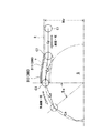
以下、本発明の高速伝動用乗り継ぎガイドの好ましい実施の形態にある実施例を図面に基づいて説明する。ここで、図1は、本発明の第1実施例である高速伝動用乗り継ぎガイド100の設置図であり、図2は、伝動チェーンのローラの移動経路を示した図であり、図3は、本発明の第2実施例である高速伝動用乗り継ぎガイド200の設置図であり、図4は、本発明の第3実施例である高速伝動用乗り継ぎガイド300の設置図であり、図5は、本発明の第4実施例である高速伝動用乗り継ぎガイド400の設置図であり、第6図は、本発明の第5実施例である高速伝動用乗り継ぎガイド500の設置図である。
【0011】
本発明の第1実施例である高速伝動用乗り継ぎガイド100は、図1に示すように、自動用エンジンのカムシャフトを所定のタイミングで高速回転させるスプロケットSと噛み合って多角形運動するタイミングチェーンと称する伝動チェーンCの速度変動を打ち消すための乗り継ぎガイドであって、多数のローラC1、C2、C3・・・を所定のチェーンピッチCpで順次枢結して直線軌道を備えた走行規制ガイドRによりチェーン内周側に押さえ込んで定速走行させたローラチェーンからなる伝動チェーンCを定速回転のスプロケットSに噛み合わせる直前の乗り継ぎ位置X2に配置されている。なお、図1の符号Sαは、スプロケットSの一歯当たりのピッチ角である。
【0012】
そして、本発明の高速伝動用乗り継ぎガイド100に形成される曲線軌道Tは、図2に示すように、伝動チェーンCの所定チェーンピッチCpで連続する3つのローラC1、C2、C3が走行規制位置X1と乗り継ぎ位置X2と噛み合い位置X3に常時対応するような配列走行状態で走行規制ガイドRからチェーン外周側に開放されながらスプロケットSに向けて噛み込んでいく場合、スプロケットSに噛み合わせる直前の乗り継ぎ位置X2において、ローラC2がローラC1、C3からそれぞれチェーンピッチCpの離間距離を保って無理なく高速度で移動できるような連続した2つの円弧状曲線T1,T2からなる移動経路に沿って規定されている。
【0013】
ここで、本発明における「走行規制位置X1」とは、直線軌道を備えた走行規制ガイドRによりチェーン内周側に押さえ込んで定速走行させた伝動チェーンCのローラC1が走行規制ガイドRを走行する移動領域のことであり、「乗り継ぎ位置X2」とは、例えば、走行規制ガイドRから送り出された伝動チェーンCのローラC2がスプロケットSに下降しながら接近して噛み合うまでの移動領域であり、「噛み合い位置X3」とは、例えば、スプロケットSに噛み合った直後のローラC3が、このローラC3に後続するローラC2がスプロケットSに噛み合うまでの移動領域である。
【0014】
また、走行規制ガイドRの設置レベルHrについては、伝動チェーンCの高速走行時に走行規制ガイドRからチェーン外周側に開放されながらスプロケットSに向けて確実に噛み込んでいくことができるとともに、前述した曲線軌道Tが連続した2つの円弧状曲線T1,T2を形成することができる設置レベル、すなわち、スプロケットSに形成される噛み合いピッチ円Spの接線(図示せず)よりチェーン内周側であれば何ら差し支えない。
【0015】
さらに、2つの円弧状曲線T1,T2の変曲点Tpについては、ローラC1、C2、C3が走行規制位置X1を走行しているローラC1と乗り継ぎ位置X2を走行しているローラC2と噛み合い位置X3を走行しているローラC3が一直線状の配列走行状態となったときのローラC2の走行位置として定めることができる。
【0016】
したがって、本発明の高速伝動用乗り継ぎガイドは、上述したような移動経路を構成する2つの円弧状曲線T1,T2にローラC1、C2、C3のローラ径を加味したガイド曲率半径に基づいて、乗り継ぎ位置X2における移動経路の少なくとも外側側に添設されるか、あるいは、内側側にも添設される。
すなわち、図1に示す第1実施例の高速伝動用乗り継ぎガイド100は、乗り継ぎ位置X2でローラ径を加味して移動経路に添設した外側ガイド111,112と内側ガイド121,122とで構成され、図3に示す第2実施例の高速伝動用乗り継ぎガイド200は、乗り継ぎ位置X2でローラ径を加味して移動経路に添設した外側ガイド211,212と内側ガイド221とで構成され、図4に示す第3実施例の高速伝動用乗り継ぎガイド300は、乗り継ぎ位置X2でローラ径を加味して移動経路に添設した外側ガイド311,312で構成され、図5に示す第4実施例の高速伝動用乗り継ぎガイド400は、乗り継ぎ位置X2でローラ径を加味して移動経路の走行規制ガイドR側に添設した外側ガイド411と内側ガイド421で構成され、図6に示す第5実施例の高速伝動用乗り継ぎガイド500は、乗り継ぎ位置X2でローラ径を加味して移動経路の走行規制ガイドR側に添設した外側ガイド511で構成される。
【0017】
以上のようにして得られた本発明の実施例である高速伝動用乗り継ぎガイド100、200、300、400、500は、伝動チェーンCの連続する3つのローラC1、C2、C3が走行規制位置X1と乗り継ぎ位置X2と噛み合い位置X3に常時対応するような配列走行状態で走行規制ガイドRからチェーン外周側に開放されながらスプロケットSに向けて噛み込んでいく場合に、スプロケットSに噛み合わせる直前の乗り継ぎ位置X2が、ローラC2がローラC1、C3からそれぞれ1チェーンピッチCpの離間距離を保って無理なく移動できるような連続した2つの円弧状曲線T1、T2からなる移動経路に沿って規定されているために、このような曲線軌道TがスプロケットSと噛み合って多角形運動する伝動チェーンCの速度変動を吸収して打ち消し、伝動チェーンCの速度ムラを解消することができる。
【0018】
したがって、自動車用エンジンのタイミングチェーンとして使用された伝動チェーンCが高速走行した場合であっても、スプロケットSと噛み合って多角形運動する伝動チェーンCに生じた速度変動を曲線軌道Tが打ち消して円滑な伝動タイミングを確実に実現でき、また、従来のような過剰の駆動動力を要することもなく、チェーン動力伝達機構の耐久性を長期に亙って確保することができる。しかも、伝動チェーンCの張力変動も解消できるので、伝動チェーンCの小型化を達成でき、伝動振動や伝動騒音を大幅に低減できるなど、その効果は甚大である。
【0019】
【発明の効果】
本発明は、直線軌道もしくは曲線軌道を備えた走行規制ガイドによりチェーン内周側に押さえ込んで定速走行させた伝動チェーンの連続する3つのローラが走行規制位置と乗り継ぎ位置と噛み合い位置に常時対応するような配列走行状態で走行規制ガイドからチェーン外周側に開放されながら定速回転のスプロケットに向けて噛み込んでいく場合、高速伝動用乗り継ぎガイドの曲線軌道が乗り継ぎ位置におけるローラの移動経路に沿って規定されていることによって、伝動チェーンが高速走行しても、この曲線軌道がスプロケットと噛み合って多角形運動する伝動チェーンの速度変動を吸収して打ち消し、伝動チェーンの速度ムラを解消することができるため、伝動チェーンの速度変動を打ち消して円滑な伝動タイミングを確実に実現できるとともに、伝動チェーンの駆動力と振動騒音を大幅に低減することができる。
【図面の簡単な説明】
【図1】本発明の第1実施例である高速伝動用乗り継ぎガイドの設置図。
【図2】伝動チェーンのローラの移動経路を示した図。
【図3】本発明の第2実施例である高速伝動用乗り継ぎガイドの設置図。
【図4】本発明の第3実施例である高速伝動用乗り継ぎガイドの設置図。
【図5】本発明の第4実施例である高速伝動用乗り継ぎガイドの設置図。
【図6】本発明の第5実施例である高速伝動用乗り継ぎガイドの設置図。
【符号の説明】
100,200,300,400,500 ・・・ 高速伝動用乗り継ぎガイド111,211,311,411,511 ・・・ 走行規制ガイドR側に添設した外側ガイド
112,212,312 ・・・ スプロケットS側に添設した外側ガイド
121,221,421 ・・・ 走行規制ガイドR側に添設した内側ガイド
122 ・・・ スプロケットS側に添設した内側ガイド
S ・・・ スプロケット
Sp ・・・ スプロケットSの噛み合いピッチ円
Sα ・・・ スプロケットSのピッチ角
C ・・・ 伝動チェーン
C1 ・・・ 走行規制ガイドRを走行するローラ
C2 ・・・ 走行規制ガイドRから送り出されたローラ
C3 ・・・ スプロケットSに噛み合った直後のローラ
Cp ・・・ チェーンピッチ
R ・・・ 走行規制ガイド
X1 ・・・ 走行規制位置
X2 ・・・ 乗り継ぎ位置
X3 ・・・ 噛み合い位置
T ・・・ 曲線軌道
T1,T2 ・・・ 円弧状曲線
Tp ・・・ 円弧状曲線T1,T2の変曲点
Hr ・・・ 走行規制ガイドRの設置レベル[0001]
TECHNICAL FIELD OF THE INVENTION
The present invention relates to a high-speed transmission used for canceling the speed fluctuation of a transmission chain that engages with a sprocket and moves in a polygonal manner in a power transmission mechanism that rotates a cam shaft of an internal combustion engine such as a vehicle engine at a high speed at a predetermined timing. This is related to a transit guide.
[0002]
[Prior art]
As a conventional technique, the chain is arranged along the running direction of the chain near the position where the chain is bitten by the sprocket so that the weight of the chain entering the sprocket does not add as much as possible to the tooth surface of the sprocket. There is a high-speed transmission path guide having a guide surface that supports the rollers of a chain, and suppresses vibration and noise generated in a chain transmission device in which power transmission is performed between sprockets that rotate at high speed ( For example, see Patent Document 1).
[0003]
[Patent Document 1]
JP-A-9-79333 (page 1, FIG. 1)
[0004]
[Problems to be solved by the invention]
However, the conventional high-speed transmission path guide has a small number of sprocket teeth because the center of the roller pivotally connected to the roller chain is designed to enter from the tangential direction of the meshing pitch circle formed on the sprocket. In some cases, the roller chain causes large speed fluctuations due to the polygonal movement caused by the rotation of the sprocket.
Due to such a large speed fluctuation of the roller chain, the intermittent transmission load generated on the sprocket and the roller chain increases as the sprocket rotating at a constant speed rotates at a high speed, and the intermittent transmission load of the sprocket is reduced. Not only does the transmission timing of an internal combustion engine such as a vehicle engine via a camshaft have a subtle adverse effect, but also the durability of a chain power transmission mechanism composed of a roller chain, a sprocket, and the like may be impaired. Was.
In addition, in order to solve such problems, there is a problem that excessive drive power is wasted by unnecessarily increasing the size and strength of the roller chain and the like, and further, transmission vibration and transmission noise are remarkably increased. There was also the problem of increase.
[0005]
Therefore, an object of the present invention is to solve the problems of the prior art as described above, and it is possible to reliably realize a smooth transmission timing by canceling the speed fluctuation of the transmission chain, and to reduce the driving force of the transmission chain. An object of the present invention is to provide a high-speed transmission connecting guide capable of significantly reducing vibration noise.
[0006]
[Means for Solving the Problems]
First, the invention according to claim 1 is arranged at a transit position immediately before the transmission chain, which has been pressed down to the inner peripheral side of the chain by the travel regulation guide and run at a constant speed, is meshed with the sprocket rotating at a constant speed, and meshes with the sprocket. A high-speed transmission connecting guide having a curved track that cancels out speed fluctuations generated in the rollers of the transmission chain that moves in a polygonal manner at the immediately engaged position, comprising three rollers continuous at a predetermined chain pitch of the transmission chain. When the gear is bitten toward the sprocket while being released from the travel control guide to the chain outer periphery in an array running state in which the rollers are always in the running control position, the transfer position, and the meshing position, the curved track is the roller at the transfer position. Being defined along the travel route solves the aforementioned issues. It is intended to.
[0007]
The invention according to claim 2 solves the above-described problem by providing the curved orbit by two continuous arc-shaped curves in addition to the configuration according to claim 1 described above. It is a solution.
[0008]
In the present invention, the “traveling restricted position” is defined as a moving area in which the rollers of the transmission chain, which have been driven at a constant speed while being pressed against the inner circumferential side of the chain by a traveling restricted guide having a straight track or a curved track, travel the traveling restricted guide. The `` transit position '' is a moving area where the rollers of the transmission chain sent out from the travel restriction guide approach the sprocket while descending and mesh with the sprocket, and the `` meshing position '' is the sprocket The roller immediately after meshing with the sprocket is a moving area until the subsequent roller meshes with the sprocket.
[0009]
[Action]
According to the transit guide for high-speed transmission of the present invention, first, three continuous rollers at a predetermined chain pitch of a transmission chain which is driven at a constant speed by being pressed down on the inner peripheral side of the chain by a travel regulation guide having a linear track or a curved track. Are engaged with the sprocket rotating at a constant speed while being released from the traveling regulation guide to the outer periphery of the chain in an arrangement traveling state in which the traveling regulation position, the transfer position, and the meshing position always correspond to each other.
At this time, the connecting guide for high-speed transmission of the present invention has a curved orbit formed by two continuous arc-shaped curves defined along the movement path of the roller at the connecting position. Periodic speed fluctuations of the transmission chain, which sometimes engages with a sprocket and moves in a polygonal shape, are absorbed and canceled, thereby eliminating the speed unevenness of the transmission chain.
[0010]
BEST MODE FOR CARRYING OUT THE INVENTION
Hereinafter, a preferred embodiment of a high-speed transmission connecting guide according to the present invention will be described with reference to the drawings. Here, FIG. 1 is an installation diagram of a high-speed transmission connecting guide 100 according to a first embodiment of the present invention, FIG. 2 is a diagram showing a moving path of a roller of a transmission chain, and FIG. FIG. 4 is an installation diagram of a high-speed transmission connection guide 200 according to a second embodiment of the present invention. FIG. 4 is an installation diagram of a high-speed transmission connection guide 300 according to a third embodiment of the present invention. FIG. 6 is an installation diagram of a high-speed transmission connection guide 400 according to a fourth embodiment of the present invention, and FIG. 6 is an installation diagram of a high-speed transmission connection guide 500 according to a fifth embodiment of the present invention.
[0011]
As shown in FIG. 1, a high-speed transmission connecting guide 100 according to a first embodiment of the present invention includes a timing chain that engages with a sprocket S that rotates a camshaft of an automatic engine at a high speed at a predetermined timing and performs a polygonal movement. A transmission guide for canceling the speed fluctuation of the transmission chain C, which is connected to a plurality of rollers C1, C2, C3,... The transmission chain C composed of a roller chain pressed at the inner circumferential side of the chain and driven at a constant speed is arranged at a connection position X2 immediately before meshing with the sprocket S rotating at a constant speed. The symbol Sα in FIG. 1 is a pitch angle per tooth of the sprocket S.
[0012]
As shown in FIG. 2, the curved track T formed on the high-speed transmission connecting guide 100 of the present invention has three rollers C1, C2, and C3 that are continuous at a predetermined chain pitch Cp of the transmission chain C. X1 and the connecting position X2 and the meshing position X3 in the arrangement traveling state, when the gear is bitten toward the sprocket S while being released from the travel regulation guide R to the outer periphery of the chain, the connecting right before the sprocket S is meshed. At the position X2, the roller C2 is defined along a movement path composed of two continuous arc-shaped curves T1 and T2 such that the roller C2 can move at a high speed without difficulty while maintaining a distance of the chain pitch Cp from the rollers C1 and C3. ing.
[0013]
Here, the “traveling restricted position X1” in the present invention means that the roller C1 of the transmission chain C, which is pressed down to the inner circumferential side of the chain by the traveling restricted guide R having a straight track and travels at a constant speed, travels along the traveling restricted guide R. The “transit position X2” is, for example, a movement region until the roller C2 of the transmission chain C sent out from the travel restriction guide R approaches the sprocket S while descending and meshes with the sprocket S. The “meshing position X3” is, for example, a moving region where the roller C3 immediately after meshing with the sprocket S is engaged with the roller C2 following the roller C3 until meshing with the sprocket S.
[0014]
The installation level Hr of the travel regulation guide R can be reliably engaged with the sprocket S while being released from the travel regulation guide R to the outer periphery of the chain during high-speed traveling of the transmission chain C, as described above. If the installation level is such that the curved orbit T can form two continuous arc-shaped curves T1 and T2, that is, if the tangent (not shown) of the meshing pitch circle Sp formed on the sprocket S is on the inner circumferential side of the chain. No problem.
[0015]
Further, regarding the inflection point Tp of the two arc-shaped curves T1 and T2, the positions at which the rollers C1, C2 and C3 mesh with the roller C1 running at the transit control position X1 and the roller C2 running at the transit position X2. It can be determined as the traveling position of the roller C2 when the roller C3 traveling on X3 is in a linear arrangement traveling state.
[0016]
Therefore, the connecting guide for high-speed transmission according to the present invention is based on the connecting radius based on the guide radius of curvature in which the roller diameters of the rollers C1, C2 and C3 are added to the two arc-shaped curves T1 and T2 constituting the moving path as described above. It is attached to at least the outer side of the movement path at the position X2, or is also attached to the inner side.
That is, the transit guide 100 for high-speed transmission of the first embodiment shown in FIG. 1 is composed of the outer guides 111 and 112 and the inner guides 121 and 122 which are added to the movement path in consideration of the roller diameter at the transit position X2. The high-speed transmission connecting guide 200 of the second embodiment shown in FIG. 3 is composed of outer guides 211 and 212 and an inner guide 221 which are added to the movement path in consideration of the roller diameter at the connecting position X2. The transfer guide 300 for high-speed transmission according to the third embodiment shown in FIG. 5 includes outer guides 311 and 312 attached to the movement path in consideration of the roller diameter at the connection position X2. The transmission connecting guide 400 includes an outer guide 411 and an inner guide 421 attached to the traveling control guide R side of the movement path in consideration of the roller diameter at the connecting position X2. Is, the fifth embodiment fast transmission for transit guide 500 shown in FIG. 6 is constituted by an outer guide 511 additionally provided to the travel restricting guide R side of the movement path in consideration of the roller diameter in transit position X2.
[0017]
The high-speed transmission connecting guides 100, 200, 300, 400, and 500 according to the embodiment of the present invention obtained as described above include three continuous rollers C1, C2, and C3 of the transmission chain C at the travel restriction position X1. When the gear is engaged toward the sprocket S while being released from the travel regulation guide R to the outer periphery of the chain in an arrangement traveling state that always corresponds to the transfer position X2 and the engagement position X3, the connection immediately before the engagement with the sprocket S The position X2 is defined along a moving path composed of two continuous arc-shaped curves T1 and T2 such that the roller C2 can move without difficulty from the rollers C1 and C3 while maintaining a distance of one chain pitch Cp. As a result, the speed fluctuation of the transmission chain C that moves in a polygonal manner by engaging such a curved track T with the sprocket S Absorbing cancellation, it is possible to eliminate the speed variation of the transmission chain C.
[0018]
Therefore, even when the transmission chain C used as the timing chain of the automobile engine runs at high speed, the curved trajectory T cancels out the speed fluctuation generated in the transmission chain C that engages with the sprocket S and moves in a polygonal manner. Transmission timing can be reliably realized, and the durability of the chain power transmission mechanism can be ensured for a long period of time without requiring excessive driving power as in the conventional case. In addition, since the fluctuation in the tension of the transmission chain C can be eliminated, the size of the transmission chain C can be reduced, and the transmission vibration and transmission noise can be greatly reduced.
[0019]
【The invention's effect】
According to the present invention, three continuous rollers of the transmission chain, which are held down to the inner circumferential side of the chain by a travel regulation guide having a straight track or a curved track and run at a constant speed, always correspond to the travel regulation position, the transit position, and the meshing position. In the case of such an array running state, when the gear is engaged toward the constant speed sprocket while being released from the travel control guide to the chain outer peripheral side, the curved trajectory of the high-speed transmission connecting guide follows the roller movement path at the connecting position By the provision, even if the transmission chain runs at high speed, this curved track meshes with the sprocket to absorb and cancel the speed fluctuation of the transmission chain that moves in a polygonal manner, thereby eliminating the speed unevenness of the transmission chain. Therefore, smooth transmission timing can be reliably realized by canceling the speed fluctuation of the transmission chain. Both can be significantly reduced noise and vibration and the driving force of the transmission chain.
[Brief description of the drawings]
FIG. 1 is an installation diagram of a high-speed transmission connecting guide according to a first embodiment of the present invention.
FIG. 2 is a diagram showing a movement path of a roller of a transmission chain.
FIG. 3 is an installation diagram of a high-speed transmission connecting guide according to a second embodiment of the present invention.
FIG. 4 is an installation diagram of a high-speed transmission connecting guide according to a third embodiment of the present invention.
FIG. 5 is an installation diagram of a high-speed transmission connecting guide according to a fourth embodiment of the present invention.
FIG. 6 is an installation diagram of a connection guide for high-speed transmission according to a fifth embodiment of the present invention.
[Explanation of symbols]
100, 200, 300, 400, 500... High-speed transmission connecting guides 111, 211, 311, 411, 511... Outer guides 112, 212, 312 attached to the travel regulation guide R side Sprocket S Outer guides 121, 221 and 421 attached to the side ... Inner guide 122 attached to the travel regulation guide R side ... Inner guide S attached to the sprocket S side ... Sprocket Sp ... Sprocket S Meshing pitch circle Sα: pitch angle C of sprocket S: transmission chain C1: roller C2 running on travel regulation guide R roller C3 fed from travel regulation guide R: sprocket S Roller Cp immediately after meshing with chain chain pitch R Traveling guide X1 Traveling regulation Position X2 ··· Transit position X3 ··· Meshing position T ··· Curved trajectory T1, T2 ··· Arc-shaped curve Tp ··· Inflection point Hr of arc-shaped curves T1 and T2 ··· Traveling guide R Installation level