JP2004231540A - Method for producing amines - Google Patents
Method for producing amines Download PDFInfo
- Publication number
- JP2004231540A JP2004231540A JP2003020090A JP2003020090A JP2004231540A JP 2004231540 A JP2004231540 A JP 2004231540A JP 2003020090 A JP2003020090 A JP 2003020090A JP 2003020090 A JP2003020090 A JP 2003020090A JP 2004231540 A JP2004231540 A JP 2004231540A
- Authority
- JP
- Japan
- Prior art keywords
- reaction
- catalyst
- reactor
- ammonia
- liquid
- Prior art date
- Legal status (The legal status is an assumption and is not a legal conclusion. Google has not performed a legal analysis and makes no representation as to the accuracy of the status listed.)
- Pending
Links
Images
Abstract
Description
【0001】
【発明の属する技術分野】
本発明は、固体触媒を用いて反応生成液の少なくとも一部をリサイクルする液相反応によってアミン類を製造する方法に関する。さらに詳細には、本発明は、製造装置からの金属の溶出を抑えた、固体触媒を用いて反応生成液の少なくとも一部をリサイクルする液相反応によってアミン類を製造する方法に関する。
【0002】
【従来の技術】
アミン類の製造には、均一系、不均一系などの方法が提案されている。
【0003】
特に、エタノールアミン類は腐食性が強く、装置材料の一部が溶解するという問題点がある。従来、触媒を用いない反応では、溶解した装置材料が反応に悪影響を及ぼすことはなかったのであるが、触媒を用いる反応では溶解した金属により触媒が悪影響を受ける場合がある。
【0004】
流動式接触分解法では、Ni,Vによる被毒によって触媒の活性低下が見られるが、被毒に耐性のある触媒を開発することにより、被毒現象を回避している。また、触媒被毒を引き起こす硫黄分や高沸点成分を原料から予め除去する方法を採用するものもある(例えば、特許文献1参照。)。
【0005】
【特許文献1】
特許第2724633号明細書
【0006】
【発明が解決しようとする課題】
したがって、本発明の目的は、反応生成液に溶解した金属イオンの付着による触媒の活性劣化を低減したアミン類の製造方法を提供することにある。
【0007】
【課題を解決するための手段】
本発明は、固体触媒を用いて反応生成液の少なくとも一部をリサイクルする液相反応によってアミン類を製造する方法において、下記式1で表されるXが1.05以上の条件で反応を行なうことを特徴とする方法:
X=A/B (1)
(ただし、式中、Aは反応器内に充填された触媒量(kg)、Bは反応生成液が接する装置の金属部分の表面積(m2)を示す。)に関する。
【0008】
【発明の実施の形態】
触媒を用いてアルカノールアミンを製造する際に、机上実験では長時間反応を行なっても触媒の活性低下が観察されなかったが、パイロットプラントでは触媒の活性または選択性が劣化することが観察された。本発明者らは、劣化触媒を分析したところ、生成したアルカノールアミンによって製造装置の金属材料である鉄、ニッケル、クロムが一部溶け出し、その金属イオンが触媒に付着した結果によるものであることを見出した。そこで、本発明者らはこの知見に基づいて、触媒の活性または選択性の劣化を低減したアミン類の製造方法を案出した。
【0009】
本発明の製造方法は、固体触媒を用いて反応生成液の少なくとも一部をリサイクルする液相反応によってアミン類を製造する方法において、下記式1で表されるXが1.05以上の条件で反応を行なうことを特徴とする:
X=A/B (1)
(ただし、式中、Aは反応器内に充填された触媒量(kg)、Bは反応生成液が接する装置の金属の表面積(m2)を示す。)。
【0010】
本発明で製造されるアミン類には、アルカノールアミン類を挙げることができる。ここでは、アルカノールアミンを代表例として以下に説明する。
【0011】
アルカノールアミンは、通常、アンモニアとアルキレンオキシドとの反応により得られる。
【0012】
本発明に使用される原料のアルキレンオキシドは、次の化学式(1):
【0013】
【化1】

(ただし、式中、R1,R2,R3およびR4は各々独立して水素原子、メチル基又はエチル基を表す。)で表されるアルキレンオキシドが好ましく、エチレンオキシド、プロピレンオキシドなどの2〜4個の炭素原子を有するアルキレンオキシドが例示される。これらの原料に対応してアルカノールアミンが得られる。
【0015】
アルカノールアミンの具体例として、次の化学式(2):
【0016】
【化2】
(ただし、式中、 R1,R2,R3およびR4は化学式(1)と同じである)で表されるモノアルカノールアミン、次の化学式(3):
【0018】
【化3】
(ただし、式中、 R1,R2,R3およびR4は化学式(1)と同じである)で表されるジアルカノールアミン;トリアルカノールアミンなどが例示される。
【0020】
本発明で使用できる固体触媒としては、液体アンモニアとアルキレンオキシドとを反応させてアルカノールアミンを製造できれば特に制限されることはなく、イオン交換樹脂、モレキュラーシーブ、シリカアルミナ、酸活性化粘土、希土類元素を耐熱性担体に担持した触媒などが例示できる。より具体的には、例えば、ゼオライト系の触媒であり、有効細孔径が0.45nmないし0.8nmであるマイクロポーラスマテリアルであり、好ましくはマイクロポーラスマテリアルを希土類でイオン交換および/または表面処理した触媒を用いるのがよい。上記有効なミクロ細孔径の範囲は、反応原料が細孔内に拡散することが困難となって活性が低下することなく、逆にトリアルカノールアミンが細孔内で生成することがなく、ジアルカノールアミンの選択率が低下することがない点で好ましい。マイクロポーラスマテリアルとしては、MFI型アルミノシリケート(いわゆるZSM−5)、MFI型フェリシリケート、MEL型アルミノシリケート(いわゆるZSM−11)、BEAなどが適当である。イオン交換する希土類元素としては、イットリウム、ランタン、セリウム、プラセオジム、ネオジム、サマリウム、テルビウム、イッテルビウムなどが用いられる。中でも、入手容易なイットリウム、ランタン、セリウムなどが好適である。内部に大きなキャビティを有するX型やY型ゼオライトは、このキャビティで大きな分子が生成できるので、細孔出入口の細孔径から期待される形状選択性を示すことは少ない。また、細孔外での反応は形状選択性が期待できないため、結晶1次粒子の外表面を外表面処理することが好ましい。外表面処理としては、高温でのスチーミング処理、四塩化珪素処理、アルコキシシラン処理等が挙げられる。
【0021】
触媒の調製方法としては、メタロシリケートは、通常、シリカ源・金属源と構造指示剤を水中に分散させ、オートクレーブ中で加熱するいわゆる水熱合成法やシリカ源・金属源と構造指示剤を濃縮乾固したゲルをオートクレーブ中で水蒸気と接触させるいわゆるドライゲル法などで調製できる。また、アルミノフォスフェート(ALPO)、メタロアルミノフォスフェート(MAPO)、シリコンアルミノフォスフェート(SAPO)もリン酸を用いる以外は、同じように水熱合成によって調製できる。また、ZSM−5、BEAなどは市販されているので、これらを用いてもよい。通常、水熱合成では生成したマイクロポーラスマテリアル中のイオン交換サイトにはアルカリ金属イオンが対カチオンとして含まれる。その状態では活性が低いことが多いので、アルカリ金属イオンを一旦NH4 +イオンでイオン交換し、その後、高温で焼成することによってプロトン型に交換することができる。また、一旦NH4 +イオンでイオン交換を行った後、多価カチオンでもう一度イオン交換することもでき、特に希土類元素で交換すると、活性、選択性とも向上することが多いので好ましい。
【0022】
工業的な利用においては、触媒を成形することが好ましい。触媒の形状としては特に制限はされないが、球形、円柱、中空円柱状のものを例示できる。メタロシリケートなどのマイクロポーラスマテリアル類は非常に微細な結晶からなっており、単独では成形性が非常に悪い。このため、成形するためには成形助剤あるいはバインダーを用いることが好ましい。その場合の成形助剤・バインダーとしては、シリカゾル、アルミナゾル、ジルコニアゾルなどの各種酸化物ゾルや粘土鉱物類などが用いられる。成形性の改善の面からはスメクタイト系やカオリンのような粘土鉱物が好ましい。成形助剤を使用する場合には、成形助剤の使用量は触媒が成形されれば特に制限はされないが、マイクロポーラスマテリアル100質量部に対し、通常、50質量部以下、さらに好ましくは40質量部以下の範囲である。また、成形してある程度の大きさになった触媒において、触媒内部の拡散の影響による活性・選択性の低下を防止するため、細孔容積を大きくすることが好ましい。このため、成形時に細孔形成剤を加えて成形し、焼成操作によって除去して、細孔容積を増加させることが好ましい。この細孔形成剤としては、例えば硝酸アンモニウム・酢酸アンモニウムなどの各種アンモニウム塩、蓚酸・尿素などの有機化合物、各種ポリマー・繊維などの非水溶性有機化合物などが挙げられる。細孔の生成効率、成形のし易さなどの面から非水溶性化合物が好適に使用でき、その非水溶性有機化合物としてはある程度吸湿性が有り、微細な粉体になっており数百度の高温処理で燃焼除去可能で有ればよく、特に結晶性セルロースが取り扱い性の面で好ましい。結晶性セルロースとしては、ろ紙や粉砕した粉末や、パルプを粉砕した粉体などが用いられる。結晶性セルロースなどの有機物の細孔形成剤を用いるときは、単なる加熱処理では分解できないので、酸素を含む窒素、ヘリウム、二酸化炭素などの気体中(空気を用いるのが便利である)で燃焼除去する。
【0023】
反応は液体アンモニアとアルキレンオキシドとを原料として、液相状態において加圧系固定床反応器を用いて行なう。アンモニアの使用量は、アルキレンオキシド1モルに対し、通常、2〜30モルの範囲である。アンモニアの使用量がアルキレンオキシドとの反応の理論量よりも過剰に用いることから、通常、反応生成物からアンモニアを分離、回収し、再度反応器へ供給する。また、反応で得られるアルカノールアミンは、例えば、モノエタノールアミン、ジエタノールアミン、トリエタノールアミンの混合物である。ジエタノールアミン、トリエタノールアミンを選択的に得る場合には、混合物を反応器へリサイクルする。さらに、選択的にジエタノールアミンを得る場合には、モノエタノールアミンだけを分離し、反応器へリサイクルすることもできる。もちろん、反応器へリサイクルする前記混合物とモノエタノールアミンを混合して用いてもよい。
【0024】
反応器は固定床反応器であり、通常、反応液体をアップフローで流す。さらに、反応器は反応効率の点から断熱型反応器であることが好ましい。
【0025】
反応温度は、常温〜200℃、反応圧は8〜15MPa程度が好ましい。反応器内を流れる液量は、通常、5kg/Hr以上であり、5〜60,000kg/Hrの範囲が好ましい。このとき、LHSV(液空間速度)は、反応温度、触媒の種類や使用量によって変るが、通常、0.5〜100hr−1の範囲である。
【0026】
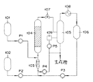
次に、本発明の製造方法に用いられる製造装置について説明する。図1は本発明で用いられる、大部分の未反応のアンモニアを除いた反応生成液の少なくとも一部をリサイクルするアルカノールアミンの製造装置の一例を示す装置説明図である。図1において、液体アンモニアタンク102から液体アンモニアを予熱器103を介して反応器104に、アルキレンオキシドタンク101からアルキレンオキシドを反応器104にそれぞれ供給する。アルキレンオキシドに対するアンモニアの添加量は、特に制限されるものではないが、アルキレンオキシド1モルに対し、通常、アンモニア2〜30モルの範囲である。予熱器103の温度は、原料を反応に先立って熱して反応温度への到達を早めることを目的とするものであり、通常、20℃〜100℃の範囲が好ましい。反応は断熱反応である。なお、各原料ポンプから圧力制御弁107までの圧力は、上記反応圧が維持される。
【0027】
反応器104から出る反応生成物は圧力制御弁107を経てフラッシュドラムなどのアンモニア回収塔105に送る。アンモニア回収塔105には、リボイラー109を取り付けてある。アンモニア回収塔105において、塔頂から冷却器108にアンモニアを導き、液体アンモニアとしてタンク106に回収するとともに、塔底にはボトム液としてアンモニア、アルカノールアミンを混合物として得る。この回収工程で、反応生成物中に含まれるアンモニアの60〜98質量%、好ましくは70〜96質量%、さらに好ましくは80〜95質量%を液体アンモニアとしてタンク106に回収する。通常、冷却器108の冷媒には常温の冷却水を用いるため、アンモニア回収塔105の操作圧は1〜3MPa程度の加圧下で操作する。このためアンモニア回収塔105の塔底から得られるボトム液中には4〜20質量%程度のアンモニアが含まれている。
【0028】
ボトム液または反応生成液の一部を反応器104または予熱器103へ供給する。生成液にはモノアルカノールアミン、ジアルカノールアミン、トリアルカノールアミンおよびアンモニアが含まれている。この混合物を反応器104へリサイクルして再度反応することにより、ジアルカノールアミンの濃度を高めた反応生成物を得ることができる。なお、圧力制御弁107以降予熱器103の手前のポンプまでは、反応に直接関係しないので反応圧よりも低くてよく、通常、2MPa程度である。
【0029】
リサイクルする反応生成液量は、全反応物量の、通常、5〜90容量%、好ましくは10〜80容量%、さらに好ましくは20〜79容量%の範囲が望ましい。リサイクル液量が少なすぎると、アルキレンオキシド濃度を上げることができず、ジアルカノールアミンを多く得ることができないからである。一方、リサイクル量が多すぎると、生産量に対する反応器入口流量が多過ぎて効率が悪くなってしまう。
【0030】
また、反応器で生成した反応生成液の一部を、アルカノールアミンとアンモニアとを完全に分離することなく、反応器へリサイクルさせることが好ましい。アンモニアを完全に分離するには、圧力を常圧〜減圧にする必要があり、コストがかかりすぎるからである。
【0031】
得られた反応生成液の一部を反応器にリサイクルさせる位置は、反応効率の面から、予熱器の入口が好ましい。
【0032】
反応器入口のアルキレンオキシド濃度は、通常、3〜35質量%、好ましくは5〜30質量%、最も好ましくは8〜25質量%の範囲である。アルキレンオキシド濃度が低すぎると、生産性が悪すぎ、ジアルカノールアミンの量が少なくなってしまう。
【0033】
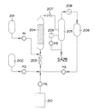
図2は本発明で用いられる、モノアルカノールアミンを反応器へリサイクルする、アルカノールアミンの製造装置の一例を示す装置説明図である。図2において、図1における符号の100の位を2とした符号は特に断りがない限り、図1と同一の部材、器具を示す。この方法では、アルカノールアミンを分離してモノアルカノールアミンを得る必要があるが、リサイクル量を減少させることができるというメリットがある。なお、モノアルカノールアミンは得られたアルカノールアミンから分離され(装置は図示せず)、タンク210に貯蔵されている。
【0034】
本発明の、固体触媒を用いて反応生成液の少なくとも一部をリサイクルする液相反応によってアミン類を製造する方法において、下記式1で表されるXが1.05以上の条件で反応を行なうことを特徴とする:
X=A/B (1)
(ただし、式中、Aは反応器内に充填された触媒量(kg)、Bは反応生成液が接する装置の金属部分の表面積(m2)を示す。)。
【0035】
式1で示されるXは1.05以上であるが、好ましくは1.05〜800の範囲である。Xの値が1.05未満であると、装置の腐食による溶解した金属イオンが触媒に付着し、触媒の活性の劣化を招くからである。本発明では、Xの値を1.05以上とすることにより、腐食による金属イオンの溶解量を抑え、それによって触媒の活性の低下を低減することができる。
【0036】
ここで、触媒量とは実際に反応器内に充填された量(kg)を示す。装置の金属部分の表面積とは、反応生成液が接する部分の表面積である(m2)。反応生成液が接する装置について、生成液の一部をリサイクルする場合と、生成液を精製してモノエタノールアミンをリサイクル場合に分けて説明する。生成液の一部をリサイクルする場合の生成液が接する装置とは、予熱器、反応器、予熱器と反応器とを結ぶ配管、アンモニア回収塔、反応器とアンモニア回収塔とを結ぶ配管、アンモニア回収塔からポンプを介して予熱器とを結ぶ配管、リボイラー、リボイラーとアンモニア回収塔とを結ぶ配管、リボイラーとポンプを介して、アンモニア回収塔からポンプを介して予熱器とを結ぶ配管とを結ぶ配管を挙げることができる。生成液を分離してモノエタノールアミンをリサイクル場合の生成液が接する装置とは、予熱器、反応器、予熱器と反応器とを結ぶ配管、アンモニア回収塔、反応器とアンモニア回収塔とを結ぶ配管、リボイラー、リボイラーとアンモニア回収塔とを結ぶ配管、リボイラーとポンプを介して、アンモニア回収塔からの配管とを結ぶ配管、モノエタノールアミン貯蔵用タンク、ポンプ、モノエタノールアミン貯蔵用タンクとポンプとを結ぶ配管、ポンプと予熱器とを結ぶ配管を挙げることができる。これらの表面積は計算に基づいて算出する。もちろん、必要により、装置を分解して測定してもよい。なお、圧力制御弁、ポンプは無視できる程度であった。
【0037】
反応生成液が接する装置の金属とは、鉄系の金属材料で構成されていることが好ましい。さらに、かかる鉄系の金属材料がステンレス鋼であることがさらに好ましい。なかでも、ステンレス鋼がFe,NiおよびCrを含んでいることが好ましい。加圧下の反応であることからある程度の強度が要求され、鉄系の金属材料を用いると、耐圧性の要求を満たすとともに、装置のコストが大幅に低減できるからである。
【0038】
反応器内には粒状の固体触媒が充填されているが、通液の際に触媒が飛散しないように、通常、触媒層の入口および出口にフィルターまたはその類似品を用い、触媒層を支持する。この材料が金属であると、腐食することから耐腐食性の材料のフィルターを用いることが好ましい。この材料としては、非金属材料が好ましく、耐熱性の観点から非金属の無機材料がより好ましい。非金属の無機材料としては、SiO2,Al2O3,ZrO2などやそれらの複合酸化物・混合物であるセラミックスやガラスなどが例示される。鉄系材料を使用する場合には、耐食性が向上することから、ガラスライニング、ホウロウ加工などを施すことが好ましい。
【0039】
【実施例】
以下、実施例により本発明について具体的に説明するが、本発明はこの実施例に限定されるものではない。
【0040】
(実施例1:生成液のリサイクル)
図1に記載のアルカノールアミンの製造方法に準じて、下記の条件で、エタノールアミンを製造した。
【0041】
触媒量:2.38kg
予熱器103:0.081m2
配管(103−104):0.031m2(内径:5mm、長さ:2m)
反応器104:0.487m2(半径:0.0335m、高さ:2.28m)
配管(104−105):0.063m2(半径:5mm、長さ:2m)
アンモニア回収塔105:0.100m2
配管(105−109):0.083m2(内径:52.7mm、長さ:0.5m)
リボイラー109:0.281m2
配管(109−ポンプP5):0.134m2(内径21.4mm、長さ:2m)
配管(105−ポンプP4):0.171m2(内径:27.2mm、長さ:2m)
配管(ポンプP4−103):0.126m2(内径:5mm、長さ:8m)
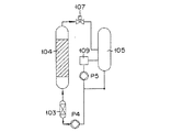
図3は、図1に示される製造装置において、リサイクルに関係する部分を特に取り上げて示す説明図面である。
【0042】
式(1)のXは1.131(2.38kg/2.104m2)であった。
【0043】
なお、装置および配管の材質はステンレス鋼であった。
【0044】
反応器104(ステンレス鋼製)にランタン担持ZSM−5ゼオライトビーズ(Si/Al原子比=28、La担持量:1質量%、ビーズ径0.7〜1.0mm)8Lを充填した。なお、反応器の原料入口側および出口側をガラスビーズで押さえて、触媒が飛散しないようにした。
【0045】
一方、反応器104の上流側に、電気ヒータを設置した管状予熱器103(直径5mmの充填物:材質シリカ)を設け、予熱部を電気ヒータで加熱した。
【0046】
次に、上記予熱器103に、高圧ポンプを用いて、液体アンモニアとエタノールアミン(反応初期は反応器出口想定組成の模擬液、定常状態ではアンモニア回収塔105のボトム液)を一定速度で連続的に送り込んだ。これにより、アンモニア原料タンク102内のアンモニアと、EO(エチレンオキシド)原料タンク101内のEOとを混合・加熱し、反応器104に供給した。反応器104は、保温のため図示しない加熱器(電気ヒータ)でわずかに加熱し、放熱で失われる熱量を供給することで、実質的に断熱状態とした。反応圧を10MPaに制御した。そして、EOとアンモニアとを連続的に反応させた。
【0047】
入口温度は40℃、反応圧は反応器出口の制御弁で10MPaに一定に制御した。反応器出口で触媒層の温度は150℃となっていた。反応器104出口にはアンモニア回収塔105を設け、圧力2MPaで運転し、大部分のアンモニアを分離し、容器106に蓄えた。
【0048】
定常状態の原料流量は、アンモニア回収塔105のボトム液を7.78kg/hrで、リサイクルアンモニアとフレッシュなアンモニアを合計5.32kg/hrで、EOは2.38kg/hrの速度で反応器104へ送り込んだ。生成液のリサイクル比率は50.3%であった。この生成液のエタノールアミン組成は、MEA/DEA/TEAの質量比で41.6/51.7/6.7であった。
【0049】
上記反応条件で6ヶ月間反応を行なったが、触媒の活性の低下は認められなかった。
【0050】
(実施例2:モノエタノールアミンのリサイクル)
実施例1において、生成液の代わりに、生成液を分離して得られたモノエタノールアミンをリサイクルする以外は、実施例1と同様に行なった。
【0051】
触媒量:2.38kg
予熱器203:0.081m2
配管(203−204):0.031m2(内径:5mm、長さ:2m)
反応器204:0.487m2(半径:0.0335m、高さ:2.28m)
配管(204−205):0.063m2(半径:5mm、長さ:4m)
アンモニア回収塔205:0.100m2
配管(205−209):0.083m2(内径:52.7mm、長さ:0.5m)
リボイラー209:0.281m2
配管(209−ポンプP5,配管):0.134m2(内径21.4mm、長さ:2m)
モノエタノールアミンタンク210:0.05m2
配管(210−ポンプP6):0.02m2(内径:5mm、長さ:65cm)
配管(ポンプP6−103):0.03m2(内径:5mm、長さ:95cm)
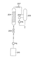
図4は、図2に示される製造装置において、リサイクルに関係する部分を特に取り上げて示す説明図面である。
【0052】
式(1)のXは1.25(2.38kg/1.91m2)であった。
【0053】
上記反応条件で6ヶ月間反応を行なったが、触媒の活性の低下は認められなかった。
【0054】
(実施例3:生成液およびMEAのリサイクル)
図1に記載のアルカノールアミンの製造方法およびMEAのリサイクルについては図2に記載のアルカノールアミンの製造方法に準じて、下記の条件で、エタノールアミンを製造した。
【0055】
触媒量:2.38kg
予熱器103:0.081m2
配管(103−104):0.031m2(内径:5mm、長さ:2m)
反応器104:0.487m2(半径:0.0335m、高さ:2.28m)
配管(104−105):0.063m2(半径:5mm、長さ:2m)
アンモニア回収塔105:0.100m2
配管(105−109):0.083m2(内径:52.7mm、長さ:0.5m)
リボイラー109:0.281m2
配管(109−ポンプ):0.134m2(内径21.4mm、長さ:2m)
配管(105−ポンプ):0.171m2(内径:27.2mm、長さ:2m)
配管(ポンプ−103):0.126m2(内径:5mm、長さ:8m)
モノエタノールアミンタンク110:0.05m2
配管(110−ポンプ):0.02m2(内径:5mm、長さ:65cm)
配管(ポンプ−103):0.03m2(内径:5mm、長さ:95cm)
式(1)のXは1.080(2.38kg/2.204m2)であった。
【0056】
なお、装置および配管の材質はステンレス鋼であった。
【0057】
定常状態の原料流量は、アンモニア回収塔105のボトム液を1.42kg/hr、MEAを0.67kg/hrで、リサイクルアンモニアとフレッシュなアンモニアを合計8.68kg/hrで、EOは2.38kg/hrの速度で反応器104へ送り込んだ。生成液のリサイクル比率は10.5%であった。この生成液のエタノールアミン組成は、MEA/DEA/TEAの質量比で59.2/34.0/6.8であった。
【0058】
上記反応条件で6ヶ月間反応を行なったが、触媒の活性の低下は認められなかった。
【0059】
(比較例1)
実施例1において、触媒層のガス入口側および出口側をガラスビーズで押さえる代わりに、ステンレス鋼製のフィルターで押さえた以外は、実施例1と同様に行なった。
【0060】
反応器入口側ステンレス鋼製のフィルター:0.03m2
反応器出口側ステンレス鋼製のフィルター:0.20m2
このとき、式(1)のXは1.021(2.38kg/2.334m2)であった。
【0061】
反応開始後、1ヶ月で触媒の活性が約30%低下したので、反応を停止した。
【0062】
【発明の効果】
本発明では、式1で表されるXが1.05以上の条件で反応を行なうので、装置から溶け出した金属イオンによる触媒の活性の劣化を抑制することができる。したがって、長期にわたり触媒を使用することができる。
【図面の簡単な説明】
【図1】は、本発明で用いられる、反応生成液の一部をリサイクルするアルカノールアミンの製造装置の一例を示す装置説明図である。
【図2】は、本発明で用いられる、モノアルカノールミンをリサイクルするアルカノールアミンの製造装置の一例を示す装置説明図である。
【図3】は、図1に示される製造装置において、リサイクルに関係する部分を特に取り上げて示す説明図面である。
【図4】は、図2に示される製造装置において、リサイクルに関係する部分を特に取り上げて示す説明図面である。
【符号の説明】
101、201…アルキレンオキシド
102、202…液体アンモニアタンク
103、203…予熱器
104、204…反応器
105、205…アンモニア回収塔
106、206…タンク
108、208…冷却器
109、209…リボイラー
210…タンク
P1〜P6…ポンプ[0001]
TECHNICAL FIELD OF THE INVENTION
The present invention relates to a method for producing amines by a liquid phase reaction in which at least a part of a reaction product liquid is recycled using a solid catalyst. More specifically, the present invention relates to a method for producing amines by a liquid phase reaction in which at least a part of a reaction product liquid is recycled by using a solid catalyst while suppressing elution of metal from a production apparatus.
[0002]
[Prior art]
For the production of amines, methods such as a homogeneous system and a heterogeneous system have been proposed.
[0003]
Particularly, ethanolamines are highly corrosive and have a problem that a part of the device material is dissolved. Conventionally, in a reaction without a catalyst, the dissolved apparatus material did not adversely affect the reaction, but in a reaction using a catalyst, the catalyst may be adversely affected by the dissolved metal.
[0004]
In the fluidized catalytic cracking method, although the activity of the catalyst is reduced due to poisoning by Ni and V, the poisoning phenomenon is avoided by developing a catalyst that is resistant to poisoning. There is also a method that removes sulfur and high-boiling components that cause catalyst poisoning from a raw material in advance (for example, see Patent Document 1).
[0005]
[Patent Document 1]
Patent No. 2724633
[0006]
[Problems to be solved by the invention]
Accordingly, an object of the present invention is to provide a method for producing amines in which catalyst activity deterioration due to adhesion of metal ions dissolved in a reaction product solution is reduced.
[0007]
[Means for Solving the Problems]
The present invention provides a method for producing amines by a liquid phase reaction in which at least a part of a reaction product liquid is recycled using a solid catalyst, wherein the reaction represented by the following formula 1 is performed under the condition that X is 1.05 or more. Method characterized by:
X = A / B (1)
(Where A is the amount of the catalyst packed in the reactor (kg), B is the surface area of the metal part of the device in contact with the reaction product liquid (m2). ).
[0008]
BEST MODE FOR CARRYING OUT THE INVENTION
In the production of alkanolamines using catalysts, no reduction in catalyst activity was observed in long-term reactions in desk experiments, but it was observed in pilot plants that catalyst activity or selectivity deteriorated. . The present inventors analyzed the deteriorated catalyst, and found that the resulting alkanolamine partially dissolved the iron, nickel, and chromium metal materials of the production apparatus, and that the metal ions adhered to the catalyst. Was found. Therefore, the present inventors have devised a method for producing amines with reduced deterioration of the activity or selectivity of the catalyst based on this finding.
[0009]
The production method of the present invention is a method for producing amines by a liquid phase reaction in which at least a part of a reaction product liquid is recycled using a solid catalyst, wherein X represented by the following formula 1 is not less than 1.05. Performing the reaction is characterized by:
X = A / B (1)
(Where A is the amount of the catalyst packed in the reactor (kg), B is the surface area of the metal of the device in contact with the reaction product liquid (m2). ).
[0010]
The amines produced in the present invention include alkanolamines. Here, alkanolamine will be described below as a representative example.
[0011]
The alkanolamine is usually obtained by reacting ammonia with an alkylene oxide.
[0012]
The raw material alkylene oxide used in the present invention has the following chemical formula (1):
[0013]
Embedded image
(However, in the formula, R1, R2, R3And R4Each independently represents a hydrogen atom, a methyl group or an ethyl group. ) Is preferred, and examples thereof include alkylene oxides having 2 to 4 carbon atoms, such as ethylene oxide and propylene oxide. An alkanolamine is obtained corresponding to these raw materials.
[0015]
As a specific example of the alkanolamine, the following chemical formula (2):
[0016]
Embedded image
(However, in the formula, R1, R2, R3And R4Is the same as the chemical formula (1)), a monoalkanolamine represented by the following chemical formula (3):
[0018]
Embedded image
(However, in the formula, R1, R2, R3And R4Is the same as in the chemical formula (1)), dialkanolamines; trialkanolamines and the like.
[0020]
The solid catalyst that can be used in the present invention is not particularly limited as long as an alkanolamine can be produced by reacting liquid ammonia with an alkylene oxide.Ion exchange resin, molecular sieve, silica alumina, acid activated clay, rare earth element Can be exemplified as a catalyst in which is supported on a heat-resistant carrier. More specifically, for example, it is a zeolite-based catalyst, a microporous material having an effective pore diameter of 0.45 nm to 0.8 nm, and preferably the microporous material is subjected to ion exchange and / or surface treatment with a rare earth. It is preferable to use a catalyst. The range of the effective micropore diameter is such that the reaction material does not easily diffuse into the pores and the activity does not decrease.On the other hand, dialkanolamine is not generated in the pores and the dialkanol This is preferable in that the selectivity of the amine does not decrease. As the microporous material, MFI-type aluminosilicate (so-called ZSM-5), MFI-type ferrisilicate, MEL-type aluminosilicate (so-called ZSM-11), BEA and the like are suitable. As the rare earth element to be ion-exchanged, yttrium, lanthanum, cerium, praseodymium, neodymium, samarium, terbium, ytterbium and the like are used. Among them, easily available yttrium, lanthanum, cerium and the like are preferable. X-type and Y-type zeolites having a large cavity inside can generate large molecules in this cavity, and thus rarely exhibit the shape selectivity expected from the pore diameter at the pore entrance. Since the reaction outside the pores cannot be expected to have shape selectivity, it is preferable to treat the outer surface of the primary crystal particles with an outer surface. Examples of the outer surface treatment include a high-temperature steaming treatment, a silicon tetrachloride treatment, and an alkoxysilane treatment.
[0021]
Metallosilicates are usually prepared by dispersing a silica source / metal source and a structure indicator in water and heating in an autoclave, or a so-called hydrothermal synthesis method, or concentrating a silica source / metal source and a structure indicator. The gel can be prepared by a so-called dry gel method in which the dried gel is brought into contact with water vapor in an autoclave. Aluminophosphate (ALPO), metalloaluminophosphate (MAPO), and silicon aluminophosphate (SAPO) can also be prepared by hydrothermal synthesis, except that phosphoric acid is used. Further, since ZSM-5, BEA and the like are commercially available, these may be used. Usually, an alkali metal ion is included as a counter cation in an ion exchange site in a microporous material generated in hydrothermal synthesis. In that state, the activity is often low, so that the alkali metal ion is4 +It can be exchanged into a proton type by ion-exchanging with ions and then firing at a high temperature. In addition, once NH4 +After the ion exchange with the ion, the ion exchange with the polyvalent cation can be performed again. In particular, the exchange with the rare earth element is preferable because both the activity and the selectivity are often improved.
[0022]
For industrial use, it is preferred to shape the catalyst. The shape of the catalyst is not particularly limited, and examples thereof include a sphere, a column, and a hollow column. Microporous materials such as metallosilicates are composed of very fine crystals, and alone have very poor moldability. Therefore, it is preferable to use a molding aid or a binder for molding. In this case, various oxide sols such as silica sol, alumina sol, and zirconia sol, clay minerals, and the like are used as the molding aid and binder. Clay minerals such as smectites and kaolin are preferred from the viewpoint of improving moldability. When a molding aid is used, the amount of the molding aid is not particularly limited as long as the catalyst is molded, but is usually 50 parts by mass or less, more preferably 40 parts by mass, per 100 parts by mass of the microporous material. Parts or less. Further, in a catalyst formed to a certain size by molding, it is preferable to increase the pore volume in order to prevent a decrease in activity and selectivity due to the influence of diffusion inside the catalyst. For this reason, it is preferable to increase the pore volume by adding a pore-forming agent at the time of molding and removing the mixture by a firing operation. Examples of the pore forming agent include various ammonium salts such as ammonium nitrate and ammonium acetate, organic compounds such as oxalic acid and urea, and water-insoluble organic compounds such as various polymers and fibers. A water-insoluble compound can be suitably used from the viewpoints of pore generation efficiency, ease of molding, etc., and as the water-insoluble organic compound, it has a certain degree of hygroscopicity, is a fine powder, and is a few hundred degrees. What is necessary is that it be combustible and removable by high-temperature treatment, and crystalline cellulose is particularly preferable in terms of handleability. As the crystalline cellulose, filter paper, pulverized powder, pulverized powder, or the like is used. When using an organic pore-forming agent such as crystalline cellulose, it cannot be decomposed by simple heat treatment, so it is burned and removed in a gas such as nitrogen containing oxygen, helium, carbon dioxide, etc. (it is convenient to use air). I do.
[0023]
The reaction is carried out using liquid ammonia and alkylene oxide as raw materials in a liquid phase using a pressurized fixed-bed reactor. The amount of ammonia used is usually in the range of 2 to 30 mol per 1 mol of the alkylene oxide. Since the amount of ammonia used is larger than the theoretical amount of the reaction with the alkylene oxide, ammonia is usually separated from the reaction product, recovered, and supplied to the reactor again. The alkanolamine obtained by the reaction is, for example, a mixture of monoethanolamine, diethanolamine, and triethanolamine. When diethanolamine and triethanolamine are selectively obtained, the mixture is recycled to the reactor. Further, when diethanolamine is selectively obtained, only monoethanolamine can be separated and recycled to the reactor. Of course, the mixture to be recycled to the reactor and monoethanolamine may be mixed and used.
[0024]
The reactor is a fixed-bed reactor, usually with the reaction liquid flowing upflow. Further, the reactor is preferably an adiabatic reactor from the viewpoint of reaction efficiency.
[0025]
The reaction temperature is preferably from room temperature to 200 ° C., and the reaction pressure is preferably from 8 to 15 MPa. The amount of liquid flowing in the reactor is usually 5 kg / Hr or more, and preferably in the range of 5 to 60,000 kg / Hr. At this time, the LHSV (liquid hourly space velocity) varies depending on the reaction temperature, the type of the catalyst and the amount used, but is usually 0.5 to 100 hr.-1Range.
[0026]
Next, a manufacturing apparatus used in the manufacturing method of the present invention will be described. FIG. 1 is an explanatory diagram showing an example of an alkanolamine production apparatus used in the present invention for recycling at least a part of a reaction product liquid from which most unreacted ammonia has been removed. In FIG. 1, liquid ammonia is supplied from a
[0027]
The reaction product from the
[0028]
A part of the bottom liquid or the reaction product liquid is supplied to the
[0029]
The amount of the reaction product liquid to be recycled is usually in the range of 5 to 90% by volume, preferably 10 to 80% by volume, more preferably 20 to 79% by volume of the total reactants. If the amount of the recycled liquid is too small, the alkylene oxide concentration cannot be increased, and a large amount of dialkanolamine cannot be obtained. On the other hand, if the recycling amount is too large, the flow rate at the reactor inlet with respect to the production amount is too large, and the efficiency becomes poor.
[0030]
Further, it is preferable that a part of the reaction product liquid generated in the reactor is recycled to the reactor without completely separating alkanolamine and ammonia. This is because in order to completely separate ammonia, the pressure needs to be reduced from normal pressure to reduced pressure, which is too costly.
[0031]
The position where a part of the obtained reaction product liquid is recycled to the reactor is preferably the inlet of the preheater from the viewpoint of reaction efficiency.
[0032]
The alkylene oxide concentration at the reactor inlet usually ranges from 3 to 35% by weight, preferably 5 to 30% by weight, most preferably 8 to 25% by weight. If the alkylene oxide concentration is too low, the productivity will be too low and the amount of dialkanolamine will decrease.
[0033]
FIG. 2 is an explanatory diagram showing an example of an alkanolamine production apparatus for recycling monoalkanolamine to a reactor used in the present invention. In FIG. 2, the same reference numerals as those in FIG. 1 denote the same members and instruments unless otherwise noted, with the reference numeral in FIG. In this method, it is necessary to separate the alkanolamine to obtain a monoalkanolamine, but there is an advantage that the amount of recycling can be reduced. The monoalkanolamine is separated from the obtained alkanolamine (the apparatus is not shown) and stored in the
[0034]
In the method of the present invention for producing amines by a liquid phase reaction in which at least a part of a reaction product liquid is recycled using a solid catalyst, the reaction is performed under the condition that X represented by the following formula 1 is 1.05 or more. Features:
X = A / B (1)
(Where A is the amount of the catalyst packed in the reactor (kg), B is the surface area of the metal part of the device in contact with the reaction product liquid (m2). ).
[0035]
X represented by the formula 1 is 1.05 or more, preferably in the range of 1.05 to 800. This is because if the value of X is less than 1.05, dissolved metal ions due to corrosion of the device adhere to the catalyst, causing deterioration of the activity of the catalyst. In the present invention, by setting the value of X to 1.05 or more, the amount of dissolution of metal ions due to corrosion can be suppressed, thereby reducing the decrease in the activity of the catalyst.
[0036]
Here, the catalyst amount indicates the amount (kg) actually charged in the reactor. The surface area of the metal part of the apparatus is the surface area of the part in contact with the reaction product liquid (m2). The apparatus in contact with the reaction product liquid will be described separately for a case where a part of the product liquid is recycled and a case where the product liquid is purified and monoethanolamine is recycled. When a part of the product solution is recycled, the device that comes into contact with the product solution includes a preheater, a reactor, a pipe connecting the preheater and the reactor, an ammonia recovery tower, a pipe connecting the reactor and the ammonia recovery tower, and ammonia. A pipe that connects the recovery tower to the preheater via a pump, a reboiler, a pipe that connects the reboiler to the ammonia recovery tower, and a pipe that connects the reboiler and the pump that connects the ammonia recovery tower to the preheater via the pump Piping can be mentioned. When the product liquid is separated and monoethanolamine is recycled, the equipment that the product liquid comes into contact with is a preheater, a reactor, a pipe connecting the preheater and the reactor, an ammonia recovery tower, and connecting the reactor and the ammonia recovery tower. Pipe, reboiler, pipe connecting reboiler and ammonia recovery tower, pipe connecting reboiler and pipe from ammonia recovery tower via pump, monoethanolamine storage tank, pump, monoethanolamine storage tank and pump And a pipe connecting the pump and the preheater. These surface areas are calculated based on the calculation. Of course, if necessary, the measurement may be performed by disassembling the device. The pressure control valve and the pump were negligible.
[0037]
The metal of the device in contact with the reaction product liquid is preferably made of an iron-based metal material. Further, it is more preferable that the iron-based metal material is stainless steel. Especially, it is preferable that stainless steel contains Fe, Ni, and Cr. This is because a certain degree of strength is required because the reaction is performed under pressure, and when an iron-based metal material is used, the requirement for pressure resistance can be satisfied and the cost of the apparatus can be significantly reduced.
[0038]
The reactor is filled with a granular solid catalyst, but usually a filter or a similar product is used at the inlet and outlet of the catalyst layer to support the catalyst layer so that the catalyst is not scattered when passing the liquid. . If this material is a metal, it corrodes, so it is preferable to use a filter made of a corrosion-resistant material. As this material, a nonmetallic material is preferable, and a nonmetallic inorganic material is more preferable from the viewpoint of heat resistance. Non-metallic inorganic materials include SiO2, Al2O3, ZrO2And their composite oxides / mixtures, such as ceramics and glass. When an iron-based material is used, it is preferable to perform glass lining, enamelling, or the like, because corrosion resistance is improved.
[0039]
【Example】
Hereinafter, the present invention will be described specifically with reference to Examples, but the present invention is not limited to these Examples.
[0040]
(Example 1: Recycling of product liquid)
Ethanolamine was produced under the following conditions according to the method for producing alkanolamine shown in FIG.
[0041]
Catalyst amount: 2.38 kg
Preheater 103: 0.081m2
Piping (103-104): 0.031m2(Inner diameter: 5mm, length: 2m)
Reactor 104: 0.487m2(Radius: 0.0335m, Height: 2.28m)
Piping (104-105): 0.063m2(Radius: 5mm, length: 2m)
Ammonia recovery tower 105: 0.100 m2
Piping (105-109): 0.083m2(Inner diameter: 52.7mm, length: 0.5m)
Reboiler 109: 0.281m2
Piping (109-pump P5): 0.134m2(Inner diameter 21.4mm, length: 2m)
Piping (105-pump P4): 0.171 m2(Inner diameter: 27.2 mm, length: 2 m)
Piping (pump P4-103): 0.126m2(Inner diameter: 5mm, length: 8m)
FIG. 3 is an explanatory drawing showing, in particular, parts related to recycling in the manufacturing apparatus shown in FIG.
[0042]
X in the formula (1) is 1.131 (2.38 kg / 2.104 m).2)Met.
[0043]
In addition, the material of the apparatus and the piping was stainless steel.
[0044]
The reactor 104 (made of stainless steel) was filled with 8 L of lanthanum-supported ZSM-5 zeolite beads (Si / Al atomic ratio = 28, La supported amount: 1% by mass, bead diameter 0.7 to 1.0 mm). The raw material inlet and outlet sides of the reactor were pressed with glass beads to prevent the catalyst from scattering.
[0045]
On the other hand, a tubular preheater 103 (filler having a diameter of 5 mm: material silica) provided with an electric heater was provided on the upstream side of the
[0046]
Next, using a high-pressure pump, liquid ammonia and ethanolamine (a simulated liquid having a presumed composition at the reactor outlet at the beginning of the reaction, and a bottom liquid of the
[0047]
The inlet temperature was controlled at 40 ° C., and the reaction pressure was kept constant at 10 MPa by a control valve at the outlet of the reactor. At the reactor outlet, the temperature of the catalyst layer was 150 ° C. An
[0048]
The raw material flow rate in the steady state is 7.78 kg / hr for the bottom liquid in the
[0049]
The reaction was carried out for 6 months under the above reaction conditions, but no decrease in the activity of the catalyst was observed.
[0050]
(Example 2: Monoethanolamine recycling)
Example 1 was repeated in the same manner as in Example 1 except that monoethanolamine obtained by separating the product solution was recycled instead of the product solution.
[0051]
Catalyst amount: 2.38 kg
Preheater 203: 0.081m2
Piping (203-204): 0.031m2(Inner diameter: 5mm, length: 2m)
Reactor 204: 0.487m2(Radius: 0.0335m, Height: 2.28m)
Piping (204-205): 0.063m2(Radius: 5mm, length: 4m)
Ammonia recovery tower 205: 0.100 m2
Piping (205-209): 0.083m2(Inner diameter: 52.7mm, length: 0.5m)
Reboiler 209: 0.281m2
Piping (209-pump P5, piping): 0.134m2(Inner diameter 21.4mm, length: 2m)
Monoethanolamine tank 210: 0.05m2
Piping (210-pump P6): 0.02 m2(Inner diameter: 5mm, length: 65cm)
Piping (pump P6-103): 0.03 m2(Inner diameter: 5mm, length: 95cm)
FIG. 4 is an explanatory drawing showing, in particular, parts related to recycling in the manufacturing apparatus shown in FIG.
[0052]
X of the formula (1) is 1.25 (2.38 kg / 1.91 m).2)Met.
[0053]
The reaction was carried out for 6 months under the above reaction conditions, but no decrease in the activity of the catalyst was observed.
[0054]
(Example 3: Recycling of product liquid and MEA)
Regarding the method for producing alkanolamine shown in FIG. 1 and the recycling of MEA, ethanolamine was produced under the following conditions according to the method for producing alkanolamine shown in FIG.
[0055]
Catalyst amount: 2.38 kg
Preheater 103: 0.081m2
Piping (103-104): 0.031m2(Inner diameter: 5mm, length: 2m)
Reactor 104: 0.487m2(Radius: 0.0335m, Height: 2.28m)
Piping (104-105): 0.063m2(Radius: 5mm, length: 2m)
Ammonia recovery tower 105: 0.100 m2
Piping (105-109): 0.083m2(Inner diameter: 52.7mm, length: 0.5m)
Reboiler 109: 0.281m2
Piping (109-pump): 0.134m2(Inner diameter 21.4mm, length: 2m)
Piping (105-pump): 0.171m2(Inner diameter: 27.2 mm, length: 2 m)
Piping (pump-103): 0.126m2(Inner diameter: 5mm, length: 8m)
Monoethanolamine tank 110: 0.05m2
Piping (110-pump): 0.02m2(Inner diameter: 5mm, length: 65cm)
Piping (pump-103): 0.03 m2(Inner diameter: 5mm, length: 95cm)
X in the formula (1) is 1.080 (2.38 kg / 2.204 m).2)Met.
[0056]
In addition, the material of the apparatus and the piping was stainless steel.
[0057]
The raw material flow rate in the steady state is 1.42 kg / hr for the bottom liquid of the
[0058]
The reaction was carried out for 6 months under the above reaction conditions, but no decrease in the activity of the catalyst was observed.
[0059]
(Comparative Example 1)
Example 1 was carried out in the same manner as in Example 1 except that the gas inlet side and the outlet side of the catalyst layer were pressed with a stainless steel filter instead of being pressed with glass beads.
[0060]
Reactor inlet side stainless steel filter: 0.03m2
Reactor outlet side stainless steel filter: 0.20m2
At this time, X in the expression (1) is 1.021 (2.38 kg / 2.334 m2)Met.
[0061]
One month after the start of the reaction, the activity of the catalyst was reduced by about 30%, so the reaction was stopped.
[0062]
【The invention's effect】
In the present invention, since the reaction is performed under the condition that X represented by the formula 1 is 1.05 or more, deterioration of the activity of the catalyst due to metal ions dissolved from the apparatus can be suppressed. Therefore, the catalyst can be used for a long time.
[Brief description of the drawings]
FIG. 1 is an explanatory view showing an example of an alkanolamine production apparatus used in the present invention for recycling a part of a reaction product liquid.
FIG. 2 is an explanatory view showing an example of an apparatus for producing an alkanolamine for recycling monoalkanolamine used in the present invention.
FIG. 3 is an explanatory drawing showing, in particular, parts related to recycling in the manufacturing apparatus shown in FIG.
FIG. 4 is an explanatory drawing showing, in particular, parts related to recycling in the manufacturing apparatus shown in FIG. 2;
[Explanation of symbols]
101, 201 ... alkylene oxide
102, 202 ... Liquid ammonia tank
103, 203… Preheater
104, 204 ... reactor
105, 205 ... ammonia recovery tower
106, 206 ... tank
108, 208 ... cooler
109, 209 ... Reboiler
210 ... Tank
P1 to P6 ... Pump
Claims (4)
X=A/B (1)
(ただし、式中、Aは反応器内に充填された触媒量(kg)、Bは反応生成液が接する装置の金属部分の表面積(m2)を示す。)。In a method for producing amines by a liquid phase reaction in which at least a part of a reaction product liquid is recycled using a solid catalyst, the reaction is performed under the condition that X represented by the following formula 1 is 1.05 or more. how to:
X = A / B (1)
(However, in the formula, A indicates the amount of the catalyst charged in the reactor (kg), and B indicates the surface area (m 2 ) of the metal part of the apparatus in contact with the reaction product liquid.)
Priority Applications (1)
| Application Number | Priority Date | Filing Date | Title |
|---|---|---|---|
| JP2003020090A JP2004231540A (en) | 2003-01-29 | 2003-01-29 | Method for producing amines |
Applications Claiming Priority (1)
| Application Number | Priority Date | Filing Date | Title |
|---|---|---|---|
| JP2003020090A JP2004231540A (en) | 2003-01-29 | 2003-01-29 | Method for producing amines |
Publications (1)
| Publication Number | Publication Date |
|---|---|
| JP2004231540A true JP2004231540A (en) | 2004-08-19 |
Family
ID=32949810
Family Applications (1)
| Application Number | Title | Priority Date | Filing Date |
|---|---|---|---|
| JP2003020090A Pending JP2004231540A (en) | 2003-01-29 | 2003-01-29 | Method for producing amines |
Country Status (1)
| Country | Link |
|---|---|
| JP (1) | JP2004231540A (en) |
Cited By (3)
| Publication number | Priority date | Publication date | Assignee | Title |
|---|---|---|---|---|
| CN103772211A (en) * | 2012-10-25 | 2014-05-07 | 中国石油化工股份有限公司 | Method for producing ethanol amine by using liquid ammonia method |
| CN103936601A (en) * | 2013-01-23 | 2014-07-23 | 中国石油化工股份有限公司 | Ammonia recovery method in ethanolamine production |
| CN105111093A (en) * | 2014-11-04 | 2015-12-02 | 合肥轩明信息科技有限公司 | Production process of ethanolamine |
-
2003
- 2003-01-29 JP JP2003020090A patent/JP2004231540A/en active Pending
Cited By (5)
| Publication number | Priority date | Publication date | Assignee | Title |
|---|---|---|---|---|
| CN103772211A (en) * | 2012-10-25 | 2014-05-07 | 中国石油化工股份有限公司 | Method for producing ethanol amine by using liquid ammonia method |
| CN103772211B (en) * | 2012-10-25 | 2016-04-13 | 中国石油化工股份有限公司 | Liquid ammonia process for caustic soda purification produces the method for thanomin |
| CN103936601A (en) * | 2013-01-23 | 2014-07-23 | 中国石油化工股份有限公司 | Ammonia recovery method in ethanolamine production |
| CN103936601B (en) * | 2013-01-23 | 2016-08-03 | 中国石油化工股份有限公司 | ammonia recovery method in ethanolamine production |
| CN105111093A (en) * | 2014-11-04 | 2015-12-02 | 合肥轩明信息科技有限公司 | Production process of ethanolamine |
Similar Documents
| Publication | Publication Date | Title |
|---|---|---|
| JP5356018B2 (en) | Method for reducing nitrogen oxide concentration in gas | |
| DK2286897T4 (en) | Device for reducing NOx and N2O content in gases | |
| US6169207B1 (en) | Process for producing dialkanolamines | |
| JP3805152B2 (en) | Method for producing alkanolamine and apparatus for producing the same | |
| CN104220147A (en) | Device and method for eliminating nox and n2o | |
| EP1043063B1 (en) | Reaction apparatus for production of alkanolamine and method for production of alkanolamine using the apparatus | |
| US20130336872A1 (en) | Method for Removing N2O and NOx From the Nitric Acid Production Process, and an Installation Suitable for Same | |
| WO2012086582A1 (en) | Process for production of tertiary amine | |
| EP0324267B1 (en) | Process for the production of alkylamines | |
| JP2004231540A (en) | Method for producing amines | |
| US6559342B1 (en) | Method of producing alkanolamines and apparatus for producing same | |
| US6566556B2 (en) | Method for production of alkanolamine and apparatus therefor | |
| EP2907571B1 (en) | Method for producing catalyst for use in production of methylamine compound, and method for producing methylamine compound | |
| JP3830329B2 (en) | Method for regenerating catalyst for alkanolamine production | |
| JP2002249470A (en) | Method and device for producing alkanol-amine | |
| JP2004285005A (en) | Method for producing amine compound | |
| JPH11221468A (en) | Catalyst for reducing nitrogen oxide and reduction of nitrogen oxide | |
| JP5090567B2 (en) | Method for producing tertiary amine | |
| JP2002028492A (en) | Producing method of diakanolamine, catalyst for producing dialkanolamine and producing method thereof | |
| JP4163405B2 (en) | Process for producing alkanolamine | |
| JP3421272B2 (en) | Reaction apparatus and production method for dialkanolamine production | |
| JP2001149796A (en) | Method for regenerating catalyst used for manufacturing alkanolamine | |
| JP2004237139A (en) | Sieving and filling method for catalyst | |
| JP2012144522A (en) | Method for producing tertiary amine | |
| Schwefer et al. | Method and device for reducing the NO X and N 2 O of gases |
Legal Events
| Date | Code | Title | Description |
|---|---|---|---|
| RD04 | Notification of resignation of power of attorney |
Free format text: JAPANESE INTERMEDIATE CODE: A7424 Effective date: 20040701 |
|
| RD04 | Notification of resignation of power of attorney |
Effective date: 20050425 Free format text: JAPANESE INTERMEDIATE CODE: A7424 |
|
| A621 | Written request for application examination |
Free format text: JAPANESE INTERMEDIATE CODE: A621 Effective date: 20050914 |
|
| A977 | Report on retrieval |
Effective date: 20081029 Free format text: JAPANESE INTERMEDIATE CODE: A971007 |
|
| A131 | Notification of reasons for refusal |
Free format text: JAPANESE INTERMEDIATE CODE: A131 Effective date: 20081111 |
|
| A02 | Decision of refusal |
Effective date: 20090310 Free format text: JAPANESE INTERMEDIATE CODE: A02 |