JP2004230134A - Vacuum cleaner - Google Patents
Vacuum cleaner Download PDFInfo
- Publication number
- JP2004230134A JP2004230134A JP2003109528A JP2003109528A JP2004230134A JP 2004230134 A JP2004230134 A JP 2004230134A JP 2003109528 A JP2003109528 A JP 2003109528A JP 2003109528 A JP2003109528 A JP 2003109528A JP 2004230134 A JP2004230134 A JP 2004230134A
- Authority
- JP
- Japan
- Prior art keywords
- vacuum cleaner
- dust
- window
- photocatalyst
- filter
- Prior art date
- Legal status (The legal status is an assumption and is not a legal conclusion. Google has not performed a legal analysis and makes no representation as to the accuracy of the status listed.)
- Granted
Links
Images


Abstract
Description
【0001】
【発明の属する技術分野】
この発明は、掃除機本体に形成された窓に透光性部材が設けられると共に、この窓に対向した位置に光触媒部材が設けられて掃除機本体内の脱臭等を行う電気掃除機に関するものである。
【0002】
【従来の技術】
従来、電気掃除機として、図11に示すようなものが知られている(例えば特許文献1参照)。
【0003】
この電気掃除機は掃除機本体1を備え、この掃除機本体1には、集塵室2が形成されると共に、この集塵室2に吸込負圧を作用させる電動送風機3が内蔵されている。また、集塵室2内の電動送風機3の吸気口3aに対向した位置には、光触媒層が形成された光触媒部材4が配設されている。
【0004】
そして、掃除機本体1の集塵室2を構成する上壁1aには、光触媒部材4の上方に位置する窓5が形成され、この窓5には光を透過させる透光性部材5aが設けられている。この透光性部材5aを透過して入射する光によって光触媒層の酸化還元作用が励起され、臭気成分が分解される。
【0005】
このような電気掃除機では、集塵室2内で発生する臭気成分を、光触媒部材4に形成された光触媒層によって分解して除去することにより、電動送風機3から排出される排気を清潔にしている。
【0006】
また、図12に示すようなものも知られている(例えば特許文献2参照)。
【0007】
図12(a)に示す6は、電気掃除機の掃除機本体に着脱自在に装着される延長管である。そして、この延長管6の内周面には、光触媒物質を含む光触媒部材7が設けられている。
【0008】
また、延長管6の周面には、長手方向に延在されたスリット6aが形成され、このスリット6aには光を透過させる透光性部材8が設けられている。この透光性部材8は両面が円弧状に膨出しており(図12(b)参照)、外方から入射した光を拡散して光触媒部材7に照射することができる。
【0009】
このような延長管6を有する電気掃除機では、延長管6内で発生した臭気成分を、光触媒部材7に含まれた光触媒物質によって分解して除去することにより、排出される排気を清潔にしている。
【0010】
【特許文献1】
特開平9−122049号公報(段落0015〜0017、図1)
【特許文献2】
特開平9−108155号公報(段落0013、段落0015、図2,3)
【0011】
【発明が解決しようとする課題】
ところで、集塵室2内に光触媒部材4が配設された電気掃除機では、電動送風機3の吸気口3aから吸い込まれる空気は、光触媒部材4に設けられたスリットの間を通過していた。そのため、光触媒部材4に塵埃が非常に付着しやすくなっていた。
【0012】
しかしながら、この光触媒部材4を容易に洗浄することができず、付着した塵埃によって光触媒層の酸化還元作用が阻害されることがあった。そのため、長期間に亘って十分な脱臭効果が得られないという問題が生じていた。
【0013】
また、延長管6の内周面に光触媒部材7が設けられた電気掃除機であっても、光触媒部材7に付着した塵埃を除去することが困難になっており、長期間に亘って十分な脱臭効果が得られなくなっていた。
【0014】
この発明は、上記問題に鑑みてなされたもので、光触媒部材に付着した塵埃を容易に除去することができ、十分な脱臭効果を長期間保持することができる電気掃除機を提供することを目的としている。
【0015】
【課題を解決するための手段】
上記課題を解決するために、この発明の電気掃除機は、集塵室が形成されると共に、この集塵室に吸込負圧を作用させる電動送風機が内蔵された掃除機本体を備え、掃除機本体には内部空間に臨む部分に窓が形成され、この窓には光を透過させる透光性部材が設けられ、この透光性部材の内側には光触媒部材が設けられて内部空間の脱臭等を行うものであり、光触媒部材は透光性部材の内側面にほぼ沿って設けられると共に、着脱自在にされていることを特徴としている。
【0016】
このような発明によれば、光触媒部材が透光性部材の内側面にほぼ沿っているので、電動送風機に吸い込まれる空気は光触媒部材を通過することがほとんどなく、塵埃が光触媒部材に付着しにくくなる。
【0017】
また、光触媒部材が着脱自在に設けられているので、この光触媒部材に塵埃が付着した場合であっても、容易に光触媒部材を洗浄することができる。そのため、付着した塵埃によって光触媒部材の酸化還元作用が阻害されることがなくなり、十分な脱臭効果を長期間に亘って保持することができる。
【0018】
【発明の実施の形態1】
以下、図面に基づいてこの発明の実施の形態1を説明する。
【0019】
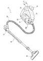
図1において、10は電気掃除機であり、掃除機本体11を備えている。掃除機本体11には、集塵ホース12の一端が着脱自在に接続され、その他端には手元操作管13が設けられている。そして、手元操作管13には着脱自在に接続された延長管14を介して吸込口体15が着脱自在に接続されている。
【0020】
掃除機本体11は、本体ケース20と、この本体ケース20の上部にヒンジ結合されて上下方向に開閉自在にされた蓋体30とを有している。
【0021】
本体ケース20の前部には、上方が開口すると共に、集塵ホース12に連通する接続口21aを有した内部空間である集塵室(集塵部)21が形成されている。また、本体ケース20の後部には、集塵室21に連通すると共に、この集塵室21に吸込負圧を作用させる電動送風機22が内蔵された内部空間である電動機室(図示せず)が形成されている。
【0022】
さらに、本体ケース20の側面には一対の車輪23(他方、図示せず)が設けられ、底面には図示しない旋回輪が設けられている。なお、集塵室21内には図示しない集塵パックが着脱自在に配設されている。
【0023】
蓋体30は、図2(a)に示すように、集塵室21の開口を覆うように設けられ、集塵室21の上側に設けられている。また、この蓋体30には、前方に突出する取っ手30aが設けられている。
【0024】
また、蓋体30には、掃除機本体11に形成された内部空間である集塵室21に臨む部分に窓31が形成されている(図3参照)。この窓31は蓋体30に形成された開口である。
【0025】
そして、この窓31の外方側には、この窓31にほぼ沿って窓カバー33が着脱自在に設けられて、窓31を覆っている。この窓カバー33の前側には、上方に持ち上げて外す際に指を掛ける指掛け部33aが形成されている。なお、この窓カバー33は、窓31の外方側の周縁部に設けられた保持スリット32dに嵌着されている。
【0026】
そして、この窓カバー33は、外部から入射する光を透過することができる透明又は半透明の透光性部材である。なお、この透光性部材は、フッ素系樹脂、アクリル樹脂、ポリカーボネート樹脂等の合成樹脂により構成されている。
【0027】
また、ここでは窓カバー33の全体が透光性部材であるが、窓31に対向する部分のみを二色成形等により透光性部材で構成しても良い。
【0028】
さらに、窓31の集塵室21側の周縁部には、前側に保持突起32aが設けられ、後側に保持リブ32bが設けられている。
【0029】
保持突起32aは窓31から所定距離離れた位置に設けられ、掃除機本体11の左右方向に延在されている。そして、この保持突起32aの先端は、R形状に形成されている(図4(a)参照)。
【0030】
一方、保持リブ32bは掃除機本体11の左右方向に所定間隔をおいて複数設けられており、窓31に向かうにつれて次第に突出すると共に、窓31近傍に保持溝32cが形成されている(図4(b)参照)。
【0031】
そして、保持突起32a及び保持リブ32bに保持されることにより、窓31にほぼ沿った状態で光触媒部材40が着脱自在に設けられている。
【0032】
このように、窓31にほぼ沿った状態で透光性部材である窓カバー33と光触媒部材40とが、それぞれ窓31に沿った状態で着脱自在に設けられている。したがって、光触媒部材40は透光性部材の内側面にほぼ沿って位置することとなる。
【0033】
また、光触媒部材40は、図2(a)に示すように、光触媒フィルタ41と、この光触媒フィルタ41を保持するフレーム体42を備えている。
【0034】
光触媒フィルタ41は、光触媒物質を含む光触媒シート41aと、竹炭物質を含む竹炭シート41bとが、ほぼ交互に重ねられて形成されている。ここで、光触媒シート41aが波形状に屈曲されており、この光触媒フィルタ41はハニカム構造となっている(図2(b)参照)。
【0035】
フレーム体42は、光触媒フィルタ41の周囲を取り囲む周壁部42aと、周壁部42aの一方開口に架け渡された複数の載置フレーム42bとを有している。光触媒フィルタ41は、周壁部42aの両側の開口を連通するように、載置フレーム42b上に載置されている。
【0036】
また、周壁部42aの他方開口の周縁部には、図4(a)、(b)に示すように、外側に向かってほぼ水平に突出した係止突部43が設けられている。この係止突部43は周縁部の全周に亘って設けられている。
【0037】
さらに、この周壁部42aの他方開口の開口端部には緩衝部材44が設けられている。この緩衝部材44により、光触媒部材40を蓋体30に取り付けた際に、窓31の周縁部にフレーム体42が直接当接することを防止する。
【0038】
次にこの電気掃除機10の作用について説明する。
【0039】
掃除機10を使用するには、あらかじめ光触媒部材40を蓋体30に取り付けておく。光触媒部材40を取り付けるには、まず蓋体30を上方に回動させて開く。そして、蓋体30の窓31の周縁部に設けられた保持突起32aに、光触媒部材40のフレーム体42に形成された係止突部43の一部を係合させる。
【0040】
そして、この保持突起32aに係合した係止突部43を回動中心として、光触媒部材40を蓋体30に向かって回動させる。このとき、保持突起32aの先端がR形状に形成されているので、スムーズに回動させることができる。
【0041】
この光触媒部材40のフレーム体42は、保持リブ32bに当接すると、次第にフレーム体42の内側に押されながら回動することとなる。そして、係止突起43と保持溝32cとが対向すると、フレーム体42の弾性力で保持溝32cに係止突起43が嵌着する。
【0042】
これにより、光触媒部材40を蓋体30に設けられている窓カバー33にほぼ沿って設けることができる。
【0043】
また、フレーム体42の周壁部42aの他方開口の開口端部には、緩衝部材44が設けられているので、窓31の周縁部にフレーム体42が直接当接せず、掃除機本体11が移動した場合等に振動が生じても、フレーム体42がガタついて異音が生じたり、外れたりすることを防止できる。
【0044】
そして、蓋体30を下方に回動させて集塵室21の開口を閉じ、手元操作管13に設けられた図示しないスイッチを入れて電動送風機22を駆動させる。
【0045】
電動送風機22が駆動すると吸込負圧が発生し、集塵室21、集塵ホース12、手元操作管13、延長管14を順に介して、吸込口体15にこの吸込負圧が作用する。
【0046】
吸込口体15に作用した吸込負圧によって、被清掃面上の塵埃及び空気が吸い込まれ、吸込口体15から延長管14、手元操作管13、集塵ホース12を順に介して、集塵室21に流れ込む。
【0047】
さらに、塵埃は集塵室21内に配設された集塵パックに捕集され、空気は電動機室内の電動送風機22に吸い込まれた後に、図示しない排気孔から外気に排出される。
【0048】
このとき、集塵室21には塵埃や空気と共に細菌等が流れ込み、アンモニア、アセトアルデヒド等の臭気成分を発散する。この臭気成分は、集塵室21の上側に位置する蓋体30に設けられた光触媒部材40によって分解され、脱臭される。また、細菌自体も光触媒部材40によって殺菌、分解される。
【0049】
なお、この光触媒部材40によって臭気成分等が分解される仕組みは以下のとおりである。
【0050】
光触媒部材40の光触媒シート41aが有する光触媒物質は、例えば二酸化チタン(TIO2)である。
【0051】
この二酸化チタンは、光(紫外線)が当たると、その表面から電子が飛び出して、正孔(ホール)と呼ばれるプラスの電荷を帯びた孔が形成される。この正孔は強い酸化力を持っており、周囲の有機物から電子を奪って電気的に安定になろうとする。
【0052】
この様に二酸化チタンの酸化還元作用によって電子を奪われた有機物は分解され、最終的には二酸化炭素や水等になり大気中に発散することとなる。
【0053】
また、竹炭シート41bは吸着力を有しており、臭気成分を吸着することができる。
【0054】
ここで、この光触媒部材40は、蓋体30に形成された窓31にほぼ沿って設けられているので、窓31から入射する光(紫外線)に十分に当たることができ、高い脱臭効果を得ることができる。
【0055】
さらに、この光触媒部材40の光触媒フィルタ41は、フレーム体42の両側の開口を連通するように設けられているので、光触媒シート41a及び竹炭シート41bの間を臭気成分が通過し、脱臭作用を励起することができる。
【0056】
また、集塵室21内に流れ込んだ空気は、蓋体30の窓31にほぼ沿って設けられた光触媒部材40を通過することがほとんどなくなく、集塵室21内に吸い込まれた塵埃が光触媒部材40に付着しにくくなる。
【0057】
そして、この光触媒部材40は蓋体30に着脱自在に設けられているので、例え光触媒部材40に塵埃が付着した場合であっても、容易に光触媒部材40を外して洗浄することができる。
【0058】
なお、光触媒部材40を外すには、まず、保持リブ32bに嵌着したフレーム体42の係止突部43を、フレーム体42の弾性力に抗してフレーム体42の内側に押し込み、保持溝32cから係止突部43を外す。続いて、係止突起32aからフレーム体42の係止突部43を外し、光触媒部材40を蓋体30から外すことができる。
【0059】
このように光触媒部材40を常に清潔にしておくことができるので、光触媒部材40に付着した塵埃によって分解作用が阻害されることがなくなり、十分な脱臭効果を長期間に亘って保持することができる。
【0060】
また、光触媒部材40が容易に洗浄できるので、光触媒フィルタ42aを集塵室21内に露出させていても、脱臭効果の低下を防止することができる。そして、この光触媒フィルタ42aが露出していることで、高い脱臭効果を得ることができる。
【0061】
一方、光触媒部材40を通過して脱臭される空気に乗って流れた塵埃が、窓カバー33に付着した場合であっても、この窓カバー33は蓋体30に着脱自在に設けられているので、外して容易に洗浄することができる。
【0062】
そのため、透光性部材である窓カバー33に塵埃が付着して、光の透過性が低下することを防止できる。そして、長期間に亘って十分な脱臭効果を保持することができる。
【0063】
なお、この窓カバー33を外すには、指掛け部33aに指先を引っ掛けて、上方に向かって窓カバー33を持ち上げる。
【0064】
また、光触媒部材40は、集塵室21に臨む部分に形成された窓31にほぼ沿って設けられているので、掃除機本体11の内部空間に生じた臭気成分等を効果的に分解、脱臭することができる。
【0065】
以上、この発明にかかる実施の形態の一つを図面により詳述してきたが、具体的な構成は上述の実施の形態に限らない。この発明の要旨を逸脱しない範囲の設計の変更等はこの発明に含まれる。
【0066】
例えば、図5に示すようなものであってもよい。
【0067】
この場合、窓カバー50の透光性部材である透光部51の外方に面した一面51aが凹レンズ形状を呈している。
【0068】
これにより、窓カバー50の透光部51を介して窓31に入射した光は、凹レンズ形状の透光部51によって屈折し、散乱されることとなる。そのため、透光部51の面積が小さくとも、広範囲に亘って光を照射することが可能となる。そして、この透光部51の面積よりも広い範囲の光触媒部材40に十分な光を当てて、高い脱臭効果を得ることができる。
【0069】
さらに、透光性部材の面積を小さくすることができるので、外観品質の向上を図ることもできる。
【0070】
また、図6に示すようなものであってもよい。
【0071】
この場合、窓カバー52は集塵室21に面した一面52aが凸レンズ形状を呈している。
【0072】
これにより、透光性部材である窓カバー52を介して窓31に入射した光は、凸レンズ形状の窓カバー52によって屈折し、集光されることとなる。そして、光が集光されることにより、紫外線の作用を強めることができて光触媒部材40の酸化還元作用をさらに励起することができる。
【0073】
このため、光触媒部材40の範囲が狭くても、高い脱臭効果を得ることができる。
【0074】
また、このように窓カバー52の集塵室21に面した一面52aを凸レンズ形状にした場合では、窓カバー52の外方に面した一面52bは比較的自由な形状にすることができる。そのため、窓カバー52の設計の自由度が阻害されず、外観品質の向上を図ることができる。
【0075】
さらに、図7に示すようなものであってもよい。
【0076】
この場合、窓カバー60の窓31に対向した部分に、透光性部材により形成された透光部61が着脱自在に設けられている。
【0077】
このため、窓カバー60の全体が蓋体30から外れるのではなく、比較的小さな透光部61だけが外れることとなる。これにより、この透光部61を容易に洗浄することができる。
【0078】
また、この透光部61を外すには、透光部61の上面に設けられたツマミ部62を掴んで上方に持ち上げる。したがって、容易に外すことができて手間が掛からない。
【0079】
また、上述の実施の形態では、内部空間が集塵室21となっているが、窓31が設けられる内部空間は集塵室21に限られず、電動機室(図示せず)や風路等であってもよい。
【0080】
【発明の実施の形態2】
以下、図面に基づいて発明の実施の形態2を説明する。なお、上述の実施の形態1と同等部位については同じ符号を用い、詳細な説明は省略する。
【0081】
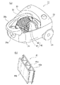
図8において、100は電気掃除機の掃除機本体であり、101は掃除機本体100の内部空間としての本体ケース、102は本体ケース101の前側に配設された内部空間としての集塵容器(集塵部)、103は集塵容器102の上方に配設されたカップ押さえ蓋である。
【0082】
また、104は本体ケース101の後部の送風機室101a内に配設された電動送風機である。この電動送風機104は、集塵容器102に連通する吸気口104aを有しており、この吸気口104aから集塵容器102内の空気を吸い込んで吸込負圧を作用させる。
【0083】
本体ケース101は、後部に送風機室101aを有するセンターケース105と、送風機室101aの下端部から前側に突出するカップ載置部106とを有している。
【0084】
そして、センターケース105の前面は前方に向かって開口し、この開口の内側には格子状壁107が設けられている。この格子状壁107は上部が送風機室101a内に向かって湾曲するように延在されており、送風機室101aの上側に凹所108を形成している(図9参照)。
【0085】
この凹所108の底面108aは格子状壁107によって構成されているので図9に示すように多数の開口が設けられ、送風機室101aと凹所108とが連通している。
【0086】
また、凹所108の上面108bには光を透過させる窓109が形成されている。この窓109はセンターケース105の上面に形成された開口であり、外部から入射する光を透過することができる透明又は半透明の透光性部材により構成された窓カバー110が設けられている。
【0087】
そして、凹所108内には光触媒部材130が着脱自在に配設されている。また、この光触媒部材130は窓カバー110の下方に位置することとなる。
【0088】
光触媒部材130は、図9に示すように、ハニカム構造に形成された光触媒フィルタ131により構成され、側面につまみ132が形成されている。
【0089】
さらに、格子状壁107の前側には、格子状に形成されたフィルタ押さえ111が着脱自在に嵌着されている。なお、111aは、フィルタ押さえ111の格子間に形成される複数の開口(連通口)であり、フィルタ膜が設けられている。
【0090】
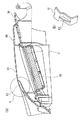
そして、格子状壁107とフィルタ押さえ111との間にはフィルタFが介装され、このフィルタFとフィルタ押さえ111とを取り付けることにより、光触媒部材130は凹所108内に収納される(図10参照)。
【0091】
集塵容器102は、後端に排気開口112が形成され、前部に吸込開口113が形成され、下端に塵埃開口114が形成された中空のカップ本体115を有している。
【0092】
そして、カップ本体115の排出開口112には、後述する2次フィルタとしてのプリーツフィルタ140が嵌着されている。
【0093】
また、カップ本体115の内部は、仕切壁116により上部及び後部側に位置する一連の負圧室117と、下部側に位置する集塵室(粗塵室)118とに区画されている。
【0094】
仕切壁116は、カップ本体115内の上下方向中間部に一体に設けられた天井壁(上壁)116aと、天井壁116aから下方に延在された後壁116bとを有している。
【0095】
そして、天井壁116aには負圧室117の上部と集塵室118とを連通させる上連通口(上排気風路)116cが上連通路として設けられ、後壁116bには負圧室117の後部と集塵室118とを連通させる後連通口(後排気風路)116dが後連通路として設けられている。そして、上連通口116cは粗塵フィルタとしてのネットフィルタ(一次フィルタ)119aで閉成され、後連通口116dは粗塵フィルタとしてのネットフィルタ(一次フィルタ)119bで閉成されている。
【0096】
また、集塵室118の下端に設けられた塵埃開口114は底蓋120で閉成されている。この底蓋120は、後端部がヒンジJで排出開口112の下部に回動可能に取り付けられている。
【0097】
また、負圧室117内には風路形成パイプ121が配設されている。この風路形成パイプ121は、前後に延びる前パイプ部121aと、前パイプ部121aの後端から側方且つ斜め下方に延びる横パイプ部121bとからL字状に形成されている。
【0098】
そして、前パイプ部121aは、前方から後方に向かうに従って徐々に縮径するテーパ状に形成されている。この前パイプ部121aには直進慣性による塵埃分離部122が設けられている。
【0099】
この塵埃分離部122は、この前パイプ部121aに設けられた複数の連通口122aと、複数の連通口122aを閉成する筒状フィルタ(粗塵フィルタである一次フィルタ)122bとを有している。この複数の連通口122aは、前後に延び且つ周方向に間隔をおいて配列されている。また、筒状フィルタ122bには、前パイプ部121aの内周面に固着された筒状のネットフィルタが用いられている。
【0100】
そして、筒状フィルタ122bの内側には、吸込開口113から連続する筒状風路123が形成されている。
【0101】
カップ押さえ蓋103は、後端部がヒンジ124を介して上下回動可能に本体ケース101のセンターケース105の上面に取り付けられている。ここで、ヒンジ124はセンターケース105の上面に形成された窓109よりも後方に設けられており、カップ押さえ蓋103を水平状態に倒したときに、カップ押さえ蓋103によって窓109が覆われることとなる。
【0102】
そして、このカップ押さえ蓋103には、窓109に対向する部分に蓋窓125が開口されている。さらに、この蓋窓125には外部から入射する光を透過することができる透明又は半透明の透光性部材により構成された窓カバー126が設けられている。
【0103】
さらに、集塵容器102の排出開口112に嵌着されたプリーツフィルタ140は、粗塵捕捉用のネットフィルタ(一次フィルタ)119a、119b及び筒状フィルタ(一次フィルタ)122bによって捕捉することができなかった細塵を捕集する二次フィルタ(細塵フィルタ)である。
【0104】
プリーツフィルタ140は、集塵容器102の後端に形成された排出開口112に嵌着されることにより、集塵容器102と電動送風機104の吸気口104aとの間に配設されることとなる。
【0105】
なお、プリーツフィルタ140は、細塵フィルタとしては、細塵を捕捉できればプリーツフィルタ140以外のフィルタ、例えば非常に目の細かいマット状のフィルタや、多層フィルタ等であっても良い。
【0106】
ここでは、プリーツフィルタ140は、枠体の内側に多数の山部と谷部とを有するジャバラ状に形成されたフィルタ膜を設けて形成されている。
【0107】
次に、この電気掃除機の作用について説明する。
【0108】
この電気掃除機を使用するには、まず、凹所108に光触媒部材130を配置する。このとき、凹所108内に形成された一対の縦壁108c、108c間に挿入することで容易に位置決めをすることができる。
【0109】
次に、フィルタFを格子状壁107に沿わせた状態でフィルタ押さえ111をセンターケース105の前面開口に嵌着する。これにより、光触媒部材130が凹所108内に収納された状態で保持される。
【0110】
そして、集塵容器102の排出開口112にプリーツフィルタ140を装着した後に、さらにこの集塵容器102を本体ケース101のカップ載置部106に装着する。集塵容器102を装着したら、カップ押さえ蓋103を水平状態に回動させて、図示しないロック手段により固定する。
【0111】
これにより、集塵容器102の吸込開口113から集塵容器102内を通って、送風機室101a内に設けられた電動送風機104の吸気口104aまでの間に風路が形成される。この風路は掃除機本体100の内部空間である。
【0112】
そして、操作パネル13のスイッチS2又はスイッチS3をON操作する。これにより、電動送風機104が駆動され、集塵容器102内の空気を吸気口104aから吸い込むことで負圧を発生させ、この負圧が本体ケース101の格子状壁107、フィルタF、格子状のフィルタ押さえ111、プリーツフィルタ140等を介して負圧室117に作用する。また、凹所108の底面108aには多数の開口が設けられて送風機室101aと連通しているので、この凹所108内にも負圧が作用する。
【0113】
そして、この負圧によって図示しない吸込口体、集塵ホース等を介して空気(エア)と共に塵埃が吸引され、この空気及び塵埃は上述の風路内に吸い込まれていく。
【0114】
このとき、空気と共に吸い込まれた塵埃のうち所定以上の質量のある塵埃は、前後方向に略直線状に延びる前パイプ部121aに設けられた塵埃分離部122内に吸引されると、塵埃分離部122に流入する際の慣性力により直進した後、横パイプ部121bを介して集塵室118の側方へ導入される。この際、空気の一部も風路形成パイプ121を介して集塵室118内に吸引される。
【0115】
また、前パイプ部121aに設けられた塵埃分離部122に吸引された空気の大半は、複数の連通口122aから筒状フィルタ122bを介して負圧室117内に吸引される。この際、前パイプ部121aに吸い込まれた塵埃のうち比較的軽い綿埃等は筒状フィルタ122bに捕捉される。しかし、細塵は筒状フィルタ122bを透過して空気と共に負圧室117内に流入する。
【0116】
このようにして、塵埃分離部122に吸い込まれる塵埃のうち所定以上の質量のある塵埃は直進慣性力により空気の一部から慣性分離される。
【0117】
さらに、集塵室118内に空気と共に吸引された塵埃は空気から分離されて集塵室118内に底部側から堆積させられる。そして、この塵埃が分離された空気は、ネットフィルタ119a及び上連通口116cを介して負圧室117の上部に吸引される一方、ネットフィルタ119b及び後連通口116dを介して負圧室117の後方側下部内に吸引される。この際、塵埃の一部はネットフィルタ119a、119bに捕捉されるが、細塵は空気と共に負圧室117内に流入する。
【0118】
このようにして負圧室117に吸い込まれた空気は、電動送風機104から作用する負圧によりプリーツフィルタ140を透過する。この際、空気に含まれる細塵は、プリーツフィルタ140に捕捉され、十分に空気中からろ過される。
【0119】
そして、プリーツフィルタ140を透過した空気は、格子状のフィルタ押さえ111、フィルタF、格子状壁107を介して電動送風機104の吸気口104aに吸い込まれた後、大気に排出される。
【0120】
ここで、プリーツフィルタ140を透過した空気は、凹所108内にも流れ込む。この空気には細塵は含まれていないが、塵埃が空気と共に流れこんだ細菌等により発散させられる臭気成分が含まれている。
【0121】
この臭気成分は凹所108内に配置された光触媒部材130によって分解され、脱臭される。また、細菌自体も光触媒部材130によって殺菌、分解される。
【0122】
ここで、この光触媒部材130は、凹所108の上面108bに形成された窓109に対向して配置され、この窓109にはカップ押さえ蓋103に開口した蓋窓125が対向している。
【0123】
そのため、光触媒部材130は、この蓋窓125および窓109から入射する光(紫外線)を十分に当てることができ、高い脱臭効果を得ることができる。
【0124】
一方、この光触媒部材130は、細塵を十分にろ過することができる2次フィルタであるプリーツフィルタ140と電動送風機104の吸気口104aとの間の風路に位置しているので、空気と共に吸い込まれた塵埃が付着することがなくなり、清潔な状態を長期間保持することができる。
【0125】
そして、光触媒部材130の表面に塵埃が付着して光に十分に当たることができなくなることが防止され、高い脱臭効果を保持することが可能となる。
【0126】
さらに、この光触媒部材130は、掃除機本体100の本体ケース101の上面に配置されているので、光により多く当たることが可能となり、より高い脱臭効果を得ることができる。
【0127】
【発明の効果】
この発明によれば、光触媒部材に付着した塵埃を容易に除去することができ、十分な脱臭効果を長期間保持することができる電気掃除機を提供することができる。
【図面の簡単な説明】
【図1】この発明に係る電気掃除機の実施例1の全体を示す斜視図である。
【図2】(a)この発明に係る電気掃除機の掃除機本体の一部を破断した斜視図である。
(b)光触媒フィルタの一部を拡大した斜視図である。
【図3】この発明に係る電気掃除機の蓋体を示す断面図である。
【図4】(a)図3におけるA部の拡大図である。
(b)図3におけるB部の拡大図である。
【図5】この実施例1に係る電気掃除機の蓋体の第1変形例を示す断面図である。
【図6】この実施例1に係る電気掃除機の蓋体の第2変形例を示す断面図である。
【図7】この実施例1に係る電気掃除機の蓋体の第3変形例を示す断面図である。
【図8】この発明に係る電気掃除機の実施例2の掃除機本体を示す斜視図である。
【図9】図8における掃除機本体のカップ押さえ蓋をあけたときの斜視図である。
【図10】図9における状態で光触媒及びフィルタ押さえを装着したときの斜視図である。
【図11】従来の電気掃除機の掃除機本体を示す断面図である。
【図12】(a)従来の電気掃除機の延長管を示す斜視図である。
(b)図12(a)におけるD−D断面図である。
【符号の説明】
10 電気掃除機
11 掃除機本体
21 集塵室
22 電動送風機
31 窓
33 透光性部材(窓カバー)
40 光触媒部材[0001]
BACKGROUND OF THE INVENTION
The present invention relates to a vacuum cleaner in which a light-transmitting member is provided in a window formed in a cleaner body, and a photocatalyst member is provided at a position facing the window to deodorize the cleaner body. is there.
[0002]
[Prior art]
Conventionally, as a vacuum cleaner, what is shown in FIG. 11 is known (for example, refer patent document 1).
[0003]
This vacuum cleaner includes a vacuum cleaner main body 1, and a
[0004]
And the window 5 located above the photocatalyst member 4 is formed in the
[0005]
In such a vacuum cleaner, odor components generated in the
[0006]
Moreover, a thing as shown in FIG. 12 is also known (for example, refer patent document 2).
[0007]
12 shown in FIG. 12A is an extension tube that is detachably attached to the vacuum cleaner body of the electric vacuum cleaner. A
[0008]
Further, a slit 6a extending in the longitudinal direction is formed on the peripheral surface of the
[0009]
In the vacuum cleaner having such an
[0010]
[Patent Document 1]
JP-A-9-1222049 (paragraphs 0015 to 0017, FIG. 1)
[Patent Document 2]
JP-A-9-108155 (paragraph 0013, paragraph 0015, FIGS. 2 and 3)
[0011]
[Problems to be solved by the invention]
By the way, in the vacuum cleaner in which the photocatalyst member 4 is disposed in the
[0012]
However, the photocatalyst member 4 cannot be easily cleaned, and the redox action of the photocatalyst layer may be hindered by the attached dust. Therefore, there has been a problem that a sufficient deodorizing effect cannot be obtained over a long period of time.
[0013]
In addition, even in a vacuum cleaner in which the
[0014]
The present invention has been made in view of the above problems, and an object thereof is to provide a vacuum cleaner that can easily remove dust adhering to a photocatalyst member and can maintain a sufficient deodorizing effect for a long period of time. It is said.
[0015]
[Means for Solving the Problems]
In order to solve the above problems, a vacuum cleaner according to the present invention includes a vacuum cleaner body in which a dust collection chamber is formed and an electric blower that applies a suction negative pressure to the dust collection chamber. A window is formed in a portion facing the internal space in the main body, and a transparent member that transmits light is provided in the window, and a photocatalyst member is provided inside the transparent member to deodorize the internal space, etc. The photocatalyst member is provided substantially along the inner surface of the translucent member and is detachable.
[0016]
According to such an invention, since the photocatalyst member is substantially along the inner surface of the translucent member, the air sucked into the electric blower hardly passes through the photocatalyst member, and dust hardly adheres to the photocatalyst member. Become.
[0017]
Moreover, since the photocatalyst member is detachably provided, the photocatalyst member can be easily washed even when dust is attached to the photocatalyst member. Therefore, the redox action of the photocatalyst member is not hindered by the attached dust, and a sufficient deodorizing effect can be maintained for a long period of time.
[0018]
DESCRIPTION OF THE PREFERRED EMBODIMENTS Embodiment 1
Embodiment 1 of the present invention will be described below with reference to the drawings.
[0019]
In FIG. 1,
[0020]
The vacuum cleaner
[0021]
A dust collection chamber (dust collection portion) 21, which is an internal space having an opening at the top and having a
[0022]
Further, a pair of wheels 23 (the other is not shown) is provided on the side surface of the
[0023]
As shown in FIG. 2A, the
[0024]
Further, the
[0025]
A
[0026]
The
[0027]
Here, the
[0028]
Further, a holding
[0029]
The holding
[0030]
On the other hand, a plurality of holding
[0031]
The
[0032]
As described above, the
[0033]
The
[0034]
The
[0035]
The
[0036]
Further, as shown in FIGS. 4A and 4B, a locking
[0037]
Further, a
[0038]
Next, the operation of the
[0039]
In order to use the cleaner 10, the
[0040]
Then, the
[0041]
When the
[0042]
Thereby, the
[0043]
Further, since the
[0044]
Then, the
[0045]
When the
[0046]
Dust and air on the surface to be cleaned are sucked in by the suction negative pressure acting on the
[0047]
Further, the dust is collected in a dust collection pack disposed in the
[0048]
At this time, bacteria and the like flow into the
[0049]
In addition, the mechanism in which an odor component etc. are decomposed | disassembled by this
[0050]
The photocatalytic substance included in the
[0051]
When this titanium dioxide is exposed to light (ultraviolet rays), electrons are ejected from the surface to form positively charged holes called holes. These holes have a strong oxidizing power and take electrons from the surrounding organic substances to make them electrically stable.
[0052]
In this way, the organic matter from which electrons have been deprived by the oxidation-reduction action of titanium dioxide is decomposed and eventually becomes carbon dioxide, water, etc., and is emitted into the atmosphere.
[0053]
Moreover, the
[0054]
Here, since this
[0055]
Further, since the
[0056]
Further, the air flowing into the
[0057]
Since the
[0058]
In order to remove the
[0059]
Since the
[0060]
Moreover, since the
[0061]
On the other hand, even if dust that has flowed through the
[0062]
Therefore, it is possible to prevent dust from adhering to the
[0063]
In order to remove the
[0064]
Moreover, since the
[0065]
Although one embodiment according to the present invention has been described in detail with reference to the drawings, the specific configuration is not limited to the above-described embodiment. Design changes and the like within the scope not departing from the gist of the present invention are included in the present invention.
[0066]
For example, it may be as shown in FIG.
[0067]
In this case, one
[0068]
As a result, the light incident on the
[0069]
Furthermore, since the area of the translucent member can be reduced, the appearance quality can be improved.
[0070]
Further, it may be as shown in FIG.
[0071]
In this case, one
[0072]
As a result, the light that has entered the
[0073]
For this reason, even if the range of the
[0074]
Further, when the one
[0075]
Furthermore, it may be as shown in FIG.
[0076]
In this case, a
[0077]
For this reason, the
[0078]
In order to remove the
[0079]
In the above-described embodiment, the internal space is the
[0080]
Second Embodiment of the Invention
The second embodiment of the present invention will be described below with reference to the drawings. In addition, the same code | symbol is used about the site | part equivalent to above-mentioned Embodiment 1, and detailed description is abbreviate | omitted.
[0081]
In FIG. 8, 100 is a vacuum cleaner main body of the vacuum cleaner, 101 is a main body case as an internal space of the vacuum cleaner
[0082]
[0083]
The
[0084]
The front surface of the
[0085]
Since the
[0086]
A
[0087]
A
[0088]
As shown in FIG. 9, the
[0089]
Further, a
[0090]
A filter F is interposed between the
[0091]
The
[0092]
A
[0093]
The interior of the
[0094]
The
[0095]
The
[0096]
The
[0097]
An air
[0098]
And the
[0099]
The
[0100]
A
[0101]
The
[0102]
The
[0103]
Furthermore, the
[0104]
The
[0105]
The
[0106]
Here, the
[0107]
Next, the operation of this electric vacuum cleaner will be described.
[0108]
In order to use this electric vacuum cleaner, first, the
[0109]
Next, the
[0110]
Then, after attaching the
[0111]
Thereby, an air path is formed from the
[0112]
Then, the switch S2 or the switch S3 on the
[0113]
The negative pressure sucks dust together with air through a suction port, a dust collecting hose and the like (not shown), and the air and dust are sucked into the above-described air passage.
[0114]
At this time, when dust having a predetermined mass or more out of the dust sucked together with the air is sucked into the
[0115]
Further, most of the air sucked into the
[0116]
In this manner, dust having a predetermined mass or more out of the dust sucked into the
[0117]
Further, the dust sucked into the
[0118]
Thus, the air sucked into the
[0119]
And the air which permeate | transmitted the
[0120]
Here, the air that has passed through the
[0121]
This odor component is decomposed and deodorized by the
[0122]
Here, the
[0123]
Therefore, the
[0124]
On the other hand, the
[0125]
In addition, it is possible to prevent dust from adhering to the surface of the
[0126]
Furthermore, since this
[0127]
【The invention's effect】
According to this invention, the vacuum cleaner which can remove easily the dust adhering to a photocatalyst member, and can hold | maintain sufficient deodorizing effect for a long period can be provided.
[Brief description of the drawings]
FIG. 1 is a perspective view showing the entirety of a first embodiment of a vacuum cleaner according to the present invention.
FIG. 2 (a) is a perspective view in which a part of the vacuum cleaner body of the electric vacuum cleaner according to the present invention is broken.
(B) It is the perspective view which expanded a part of photocatalyst filter.
FIG. 3 is a cross-sectional view showing a lid of the electric vacuum cleaner according to the present invention.
4A is an enlarged view of a part A in FIG. 3;
(B) It is an enlarged view of the B section in FIG.
FIG. 5 is a cross-sectional view showing a first modification of the lid of the electric vacuum cleaner according to the first embodiment.
FIG. 6 is a cross-sectional view illustrating a second modification of the lid of the electric vacuum cleaner according to the first embodiment.
FIG. 7 is a cross-sectional view illustrating a third modification of the lid of the electric vacuum cleaner according to the first embodiment.
FIG. 8 is a perspective view showing a vacuum cleaner body of a second embodiment of the electric vacuum cleaner according to the present invention.
9 is a perspective view when the cup holding lid of the cleaner body in FIG. 8 is opened.
10 is a perspective view when the photocatalyst and the filter retainer are mounted in the state shown in FIG. 9. FIG.
FIG. 11 is a cross-sectional view showing a vacuum cleaner body of a conventional electric vacuum cleaner.
FIG. 12 (a) is a perspective view showing an extension tube of a conventional electric vacuum cleaner.
(B) It is DD sectional drawing in Fig.12 (a).
[Explanation of symbols]
10 vacuum cleaner
11 Vacuum cleaner body
21 Dust collection chamber
22 Electric blower
31 windows
33 Translucent member (window cover)
40 Photocatalyst member
Claims (8)
前記光触媒部材は前記透光性部材の内側面にほぼ沿って位置すると共に、着脱自在に設けられていることを特徴とする電気掃除機。A dust collector is formed, and includes a vacuum cleaner main body with a built-in electric blower that applies suction negative pressure to the dust collector, and a window is formed in a portion facing the internal space in the vacuum cleaner main body, The window is provided with a translucent member that transmits light, and a photocatalyst member is provided inside the translucent member to deodorize the internal space, etc.
The vacuum cleaner, wherein the photocatalyst member is positioned substantially along an inner surface of the translucent member and is detachable.
前記光触媒部材は前記透光性部材の内側面にほぼ沿って位置すると共に、前記透光性部材は着脱自在に設けられていることを特徴とする電気掃除機。A dust collector is formed, and includes a vacuum cleaner main body with a built-in electric blower that applies suction negative pressure to the dust collector, and a window is formed in a portion facing the internal space in the vacuum cleaner main body, The window is provided with a translucent member that transmits light, and a photocatalyst member is provided inside the translucent member to deodorize the internal space, etc.
The vacuum cleaner, wherein the photocatalyst member is positioned substantially along an inner surface of the translucent member, and the translucent member is detachably provided.
Priority Applications (1)
| Application Number | Priority Date | Filing Date | Title |
|---|---|---|---|
| JP2003109528A JP4263013B2 (en) | 2002-12-03 | 2003-04-14 | Electric vacuum cleaner |
Applications Claiming Priority (2)
| Application Number | Priority Date | Filing Date | Title |
|---|---|---|---|
| JP2002350879 | 2002-12-03 | ||
| JP2003109528A JP4263013B2 (en) | 2002-12-03 | 2003-04-14 | Electric vacuum cleaner |
Publications (2)
| Publication Number | Publication Date |
|---|---|
| JP2004230134A true JP2004230134A (en) | 2004-08-19 |
| JP4263013B2 JP4263013B2 (en) | 2009-05-13 |
Family
ID=32964393
Family Applications (1)
| Application Number | Title | Priority Date | Filing Date |
|---|---|---|---|
| JP2003109528A Expired - Fee Related JP4263013B2 (en) | 2002-12-03 | 2003-04-14 | Electric vacuum cleaner |
Country Status (1)
| Country | Link |
|---|---|
| JP (1) | JP4263013B2 (en) |
Cited By (4)
| Publication number | Priority date | Publication date | Assignee | Title |
|---|---|---|---|---|
| CN100339037C (en) * | 2005-01-13 | 2007-09-26 | 松下电器产业株式会社 | Electric dust collector |
| EP1937128A2 (en) * | 2005-09-23 | 2008-07-02 | Royal Appliance MFG. CO. | Vacuum cleaner with ultraviolet light source and ozone |
| IT202000000088A1 (en) * | 2020-01-07 | 2021-07-07 | Materassificio Montalese S P A | METHOD AND CONDITIONING SYSTEM OF USED MATTRESSES |
| WO2021140454A1 (en) * | 2020-01-07 | 2021-07-15 | Materassificio Montalese S.P.A. | Method and system for conditioning used mattresses |
Families Citing this family (1)
| Publication number | Priority date | Publication date | Assignee | Title |
|---|---|---|---|---|
| RU2577732C2 (en) | 2011-12-28 | 2016-03-20 | Кабусики Кайся Тосиба | Electric vacuum cleaner |
-
2003
- 2003-04-14 JP JP2003109528A patent/JP4263013B2/en not_active Expired - Fee Related
Cited By (5)
| Publication number | Priority date | Publication date | Assignee | Title |
|---|---|---|---|---|
| CN100339037C (en) * | 2005-01-13 | 2007-09-26 | 松下电器产业株式会社 | Electric dust collector |
| EP1937128A2 (en) * | 2005-09-23 | 2008-07-02 | Royal Appliance MFG. CO. | Vacuum cleaner with ultraviolet light source and ozone |
| EP1937128A4 (en) * | 2005-09-23 | 2009-12-30 | Royal Appliance Mfg | Vacuum cleaner with ultraviolet light source and ozone |
| IT202000000088A1 (en) * | 2020-01-07 | 2021-07-07 | Materassificio Montalese S P A | METHOD AND CONDITIONING SYSTEM OF USED MATTRESSES |
| WO2021140454A1 (en) * | 2020-01-07 | 2021-07-15 | Materassificio Montalese S.P.A. | Method and system for conditioning used mattresses |
Also Published As
| Publication number | Publication date |
|---|---|
| JP4263013B2 (en) | 2009-05-13 |
Similar Documents
| Publication | Publication Date | Title |
|---|---|---|
| KR100456167B1 (en) | Dust collecting filter for vacuum cleaner and vacuum cleaner having the same | |
| JP3764410B2 (en) | Cyclone dust collector for vacuum cleaner and vacuum cleaner provided with the same | |
| JP3999791B2 (en) | Electric vacuum cleaner | |
| US20070039127A1 (en) | Dust container of upright type vacuum cleaner and supporting structure for cover thereof | |
| KR20040075573A (en) | Dust collecting container for vacuum cleaner | |
| KR20000076540A (en) | A dust collector for using the cleaner and a upright cleaner | |
| JP4946705B2 (en) | Air purification unit | |
| KR20190023212A (en) | Air purifier | |
| CA2419162A1 (en) | Vacuum cleaner | |
| JP2004174206A (en) | Dust collecting filter for vacuum cleaner and vacuum cleaner provided with the same | |
| KR20010108805A (en) | Up-right type vacuum cleaner having cyclone dust-collecting apparatus | |
| JP4263013B2 (en) | Electric vacuum cleaner | |
| JP2002102121A (en) | Electric vacuum cleaner | |
| KR100478635B1 (en) | Filter for vacuum cleaner | |
| JP2008036214A (en) | Vacuum cleaner | |
| JP2001314354A (en) | Electric vacuum cleaner | |
| JP2013027545A (en) | Vacuum cleaner | |
| KR102151548B1 (en) | Air cleaner | |
| JP2004061077A (en) | Air cleaner | |
| JP2009233054A (en) | Vacuum cleaner | |
| JP2006217941A (en) | Vacuum cleaner | |
| JPH07284465A (en) | Vacuum cleaner | |
| CN219572195U (en) | Indoor air purification device | |
| TWI753493B (en) | Vacuum cleaner | |
| JP2006043236A (en) | Dust bag for vacuum cleaner, and vacuum cleaner mount with the dust bag |
Legal Events
| Date | Code | Title | Description |
|---|---|---|---|
| A621 | Written request for application examination |
Free format text: JAPANESE INTERMEDIATE CODE: A621 Effective date: 20050909 |
|
| A711 | Notification of change in applicant |
Free format text: JAPANESE INTERMEDIATE CODE: A711 Effective date: 20070605 |
|
| A977 | Report on retrieval |
Free format text: JAPANESE INTERMEDIATE CODE: A971007 Effective date: 20080218 |
|
| A131 | Notification of reasons for refusal |
Free format text: JAPANESE INTERMEDIATE CODE: A131 Effective date: 20080226 |
|
| A521 | Written amendment |
Free format text: JAPANESE INTERMEDIATE CODE: A523 Effective date: 20080428 |
|
| A131 | Notification of reasons for refusal |
Free format text: JAPANESE INTERMEDIATE CODE: A131 Effective date: 20080902 |
|
| A521 | Written amendment |
Free format text: JAPANESE INTERMEDIATE CODE: A523 Effective date: 20081031 |
|
| TRDD | Decision of grant or rejection written | ||
| A01 | Written decision to grant a patent or to grant a registration (utility model) |
Free format text: JAPANESE INTERMEDIATE CODE: A01 Effective date: 20090203 |
|
| A01 | Written decision to grant a patent or to grant a registration (utility model) |
Free format text: JAPANESE INTERMEDIATE CODE: A01 |
|
| A61 | First payment of annual fees (during grant procedure) |
Free format text: JAPANESE INTERMEDIATE CODE: A61 Effective date: 20090210 |
|
| FPAY | Renewal fee payment (event date is renewal date of database) |
Free format text: PAYMENT UNTIL: 20120220 Year of fee payment: 3 |
|
| R150 | Certificate of patent or registration of utility model |
Ref document number: 4263013 Country of ref document: JP Free format text: JAPANESE INTERMEDIATE CODE: R150 Free format text: JAPANESE INTERMEDIATE CODE: R150 |
|
| FPAY | Renewal fee payment (event date is renewal date of database) |
Free format text: PAYMENT UNTIL: 20130220 Year of fee payment: 4 |
|
| FPAY | Renewal fee payment (event date is renewal date of database) |
Free format text: PAYMENT UNTIL: 20140220 Year of fee payment: 5 |
|
| S111 | Request for change of ownership or part of ownership |
Free format text: JAPANESE INTERMEDIATE CODE: R313115 Free format text: JAPANESE INTERMEDIATE CODE: R313117 |
|
| S531 | Written request for registration of change of domicile |
Free format text: JAPANESE INTERMEDIATE CODE: R313531 |
|
| S533 | Written request for registration of change of name |
Free format text: JAPANESE INTERMEDIATE CODE: R313533 |
|
| R350 | Written notification of registration of transfer |
Free format text: JAPANESE INTERMEDIATE CODE: R350 |
|
| LAPS | Cancellation because of no payment of annual fees |