JP2004230032A - Infusion bag pressurizing apparatus - Google Patents
Infusion bag pressurizing apparatus Download PDFInfo
- Publication number
- JP2004230032A JP2004230032A JP2003024551A JP2003024551A JP2004230032A JP 2004230032 A JP2004230032 A JP 2004230032A JP 2003024551 A JP2003024551 A JP 2003024551A JP 2003024551 A JP2003024551 A JP 2003024551A JP 2004230032 A JP2004230032 A JP 2004230032A
- Authority
- JP
- Japan
- Prior art keywords
- infusion bag
- bag
- infusion
- pressurizing
- pressure
- Prior art date
- Legal status (The legal status is an assumption and is not a legal conclusion. Google has not performed a legal analysis and makes no representation as to the accuracy of the status listed.)
- Pending
Links
Images


Abstract
Description
【0001】
【発明の属する技術分野】
本発明は、点滴や観血的血圧モニタや外科的洗浄等に使用される輸液バッグ加圧装置に関する。
【0002】
【従来の技術】
医療現場においては、水分、電解質、栄養素などを経静脈的または経口的に投与する輸液や、健康人の血液の全部または所定の成分を分離したものを患者の血管内へ注入する輸血が行われる。輸液速度や輸血が遅い場合は、液体の移動は重力によって行われるが、短時間に多量の液体を投与する必要がある場合には、輸液バッグに圧力をかけて積極的に液体を押し出し、輸液(輸血を含む。以下同じ)を投与する速度を速めることが行われている。
【0003】
このような輸液投与には、患者の血管に輸液を注入するいわゆる点滴と呼ばれるものや重症の患者に対して行う観血的血圧モニタと併行して行われるもの等が存在する。観血的モニタとは、血圧をモニタしながら、採血を時折行うものである。
【0004】
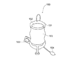
加圧する点滴装置としては、たとえば図19に示されるようなポータブル点滴装置が知られている。この点滴装置100は、空気の注入によって膨張するチャンバ101と、このチャンバ101に固定され、チャンバ101の面との間に輸液バッグ102をはさみ込むバッグ保持部103と、チャンバ101に送入する空気を発生する手動式のゴムフイゴ104と、チャンバ101に取り付けられる圧力計105と、を有している。なお、チャンバ101の輸液バッグ102に当接する側はゴム製とされている。
【0005】
このような手動タイプのポータブル点滴装置は、低価格であり、また操作が容易であることから多くの医療現場で採用されている。しかし、この種の加圧する点滴装置は、輸液バッグ102内の輸液が徐々に無くなっていくと、加圧する圧力が減少していくこととなるが、その圧力減少に気がつかない場合が多く、事故につながる危険性を有している。
【0006】
このため、特許文献1(特開2002−239002)の図5から図7に示されるように、加圧バッグ(チャンバ101に相当)の圧力を検出し自動的に加圧値を一定範囲内にしたり、滴下数をカウントし、その値から加圧バッグの圧力を制御したりすることで、常に一定の滴下数すなわち加圧力を得るようにした技術が開発されている。
【0007】
また、特許文献2(特表2000−507463)には、加圧空間の空間を水のしずくのような形状、すなわち輸液バッグが重力で変形した状態と略同様な形状とすることで、加圧バッグの圧力がシステム上必要とされる圧力値までに到達する時間を短くし、また輸液バッグ中の残液の発生を防止する発明が開示されている。
【0008】
【特許文献1】特開2002−239002号公報(図5〜図7)
【特許文献2】特表2000−507463号公報(要約書)
【0009】
【発明が解決しようとする課題】
従来の手動式の加圧点滴装置100のチャンバ101は、ゴム製とされている。また、特許文献1、2に示される自動の点滴装置の一部にも、チャンバ101に相当する加圧バッグをゴム製としているものが存在する。このようにゴム製の加圧バッグとすると、内包する空気量が大きくなるに従い、加圧バッグの全体形状が変化してしまう。この結果、昇圧速度が小さくなり、所定の圧力まで到達する時間が長くなってしまうと共に、加圧バッグ自体の伸びによって輸液バッグへの加圧が不安定となり易い。
【0010】
なお、特許文献1では、加圧バッグの一方の内部側面に硬質板状部材を固定することで、加圧バッグの形状を安定させ、輸液バッグを均一に加圧するようにしている。しかし、この特許文献1の発明では、加圧バッグの他方の内部側面は柔軟な材質とされているため、加圧バッグの形状は加圧によって変形していく。このため、輸液バッグへの加圧が不安定となる問題は依然として解消されていない。しかも、この特許文献1の発明では、輸液バッグを挿入する際、加圧バッグの上方の開口が不十分で、輸液バッグを設置しづらいという問題も発生する。
【0011】
また、特許文献2記載の発明では、輸液バッグを入れるしずく形の空間を形成するベースとドアが共に容易には変形しない構成とされているため、加圧によっての形状変更が生じず安定した加圧が可能となっている。しかし、この特許文献2記載の発明では、ドアを開いてしずく形の空間に輸液バッグを入れ、その後ドアを閉じ固定するという一連の作業を必要とする。これはスピードが要請される医療現場では好ましいものとは言えない。
【0012】
また、手動式の点滴装置100や特許文献1の自動式の点滴装置や特許文献2の自動式の輸液バッグ加圧装置のいずれにおいても、輸液バッグを加圧する面は一方側に限定されている。このため膨張する部分の伸張度が大きいものとなる。排気をすばやく行うには、収縮度合いを大きくする必要がある。しかし、伸張度が大きくなると、この収縮度はどうしても小さくなってしまう。
【0013】
また、重力を利用した自動落下式の装置の場合は、輸液バッグ中の輸液残量は、その量が減少すると、徐々に輸液上端が下降していくため、一見して判読できる。しかし、加圧式の装置の場合、輸液バッグに常に一定の圧力が加えられているため、輸液が減少しても、その輸液の上端は下がらない。この結果、輸液の残量表示は、滴下数を検知し、その値から残量を推定するという方法によって初めて可能となる。しかし、滴下数の検知機構を付加することは、装置が高価格となると共に、その推定値と実際の値との間の差が大きく変動する(誤差が大きい)という新たな問題が発生する。
【0014】
また、特許文献1、2記載の自動式の加圧装置では、圧力センサが圧力値を検知し、所定以下となると空気ポンプ等の加圧手段を駆動させ、所定以上となると加圧手段を停止させることで、一定範囲内値に加圧力が維持されるようになっている。このため、輸液バッグを他のものに取り換えたいような場合には、一旦、装置全体をオフさせた後、排気させる必要がある。すなわち、装置をオフせずに排気を開始すると、排気によって減圧が生じ、その減圧を圧力センサが検知してしまい、加圧手段を駆動させてしまう。このため、排気しようとしても排気がなされないこととなるためである。
【0015】
この問題を防止するため、特許文献1、2記載のような自動式の加圧装置では装置全体をオフした後で、排気を行うか、圧力センサまたは空気ポンプの駆動を無効化または圧力センサの検知信号を無効化するための排気準備スイッチを別に設ける必要がある。しかし、装置全体をオフする場合、各種の設定した内容が失われてしまったり表示が消滅してしまう。また、排気準備スイッチを別に設ける場合は、排気弁用のスイッチとは別に、さらにスイッチを設ける必要が生ずると共に、制御部のコントロールが複雑となる。
【0016】
また、特許文献1には、加圧バッグ手段の前面に、モニタ部付きの制御ユニットを固定配置する技術が開示されている。しかし、この制御ユニットは、変形可能な前面側に取り付けられており、加圧が均一化されない大きな要因となる。しかも、モニタ部に表示される値は、加圧バッグ内の圧力、輸液の滴下速度、輸液の滴下量、輸液バッグ内の輸液残量及び点滴時間となっており、現在動作中(加圧状態)が非動作中(排気状態)なのかを示す表示はなされない。このため、輸液バッグを取り出して良いのか悪いのかの判断がしづらい。
【0017】
本発明は、上述の問題点を解決するためになされたものであり、輸液バッグを簡単かつスピーディにセットでき、しかも輸液バッグへの加圧の安定化と、排気の高速化を達成できる輸液バッグ加圧装置を提供することを目的とする。また、他の発明は、輸液バッグ中の残量を特別な検知装置を付加することなく、簡単な機構で精度良く検出し、表示できる輸液バッグ加圧装置を提供することを目的とする。
【0018】
さらに、他の発明は、排気準備スイッチなどの特別なスイッチを設けることなく、しかも装置全体をオフすることなく、排気を可能とした輸液バッグ加圧装置を提供することを目的とする。また、他の発明は、輸液バッグを簡単かつスピーディにセットできると共に、排気の高速化を達成できる輸液バッグ加圧装置を提供することを目的とする。加えて、他の発明は、輸液バッグを簡単かつスピーディにセットでき、しかも輸液バッグを取り出しても良いか否かの判断が容易となる輸液バッグ加圧装置を提供することを目的とする。
【0019】
【課題を解決するための手段】
上述の目的を達成するため、本発明の輸液バッグ加圧装置は、上部が開口し断面長方形となる四角柱状の輸液バッグ挿入空間を有し、容易には変形しないホルダと、輸液バッグの挿入を可能とする中央空間を形成するようにホルダの内部側壁に沿って配置されると共に、4つの内部側壁のうち相対向する2つの大面積の内部側壁に沿う部分が気体の注入によって膨張可能な膨張可能部とされている加圧バッグと、加圧バッグの膨張可能部に気体を供給し、輸液バッグを加圧する加圧手段と、加圧手段による加圧力を検出する圧力センサとを有している。
【0020】
本発明の輸液バッグ加圧装置によれば、ホルダと加圧バッグの工夫によって、輸液バッグを簡単かつスピーディにセットでき、しかも輸液バッグへの加圧の安定化と、排気の高速化を達成することができる。
【0021】
他の発明の輸液バッグ加圧装置は、輸液バッグ挿入空間を有し、容易に変形しないホルダと、挿入される輸液バッグに対向可能に輸液バッグ挿入空間内に配置されると共にホルダの内部側壁に沿って配置され、かつ気体の注入によって膨張可能な膨張可能部を備える加圧バッグと、加圧バッグの膨張可能部に気体を供給し、輸液バッグを加圧する加圧手段となる加圧ポンプと、加圧ポンプの回転数または回転時間を検出するポンプ駆動検出手段と、加圧ポンプの駆動開始から輸液バッグ内の輸液が空になるまでの加圧ポンプの回転数または回転時間を予め保存し、その値とポンプ駆動検出手段による検出値とを利用して輸液バッグの残量を計算し、その値を表示部に表示する残量表示手段と、加圧手段による加圧力を検出する圧力センサとを有している。
【0022】
この発明の輸液バッグ加圧装置によると、加圧ポンプの特性を生かすことで、輸液バッグ中の残量を特別な検知装置を付加することなく、簡単な機構で精度良く検出し、表示できるものとなる。
【0023】
さらに、他の発明の輸液バッグ加圧装置は、輸液バッグ挿入空間を有し、容易に変形しないホルダと、挿入される輸液バッグに対向可能に輸液バッグ挿入空間内に配置されると共にホルダの内部側壁に沿って配置され、かつ気体の注入によって膨張可能な膨張可能部を備える加圧バッグと、加圧バッグの膨張可能部に気体を供給し、輸液バッグを加圧する加圧手段と、加圧手段による加圧力を検出する圧力センサと、圧力センサの値が所定値を越えたら加圧手段に停止信号を送出し、圧力センサの値が他の所定値を下回ったら加圧手段に駆動信号を送出すると共に圧力センサの値の減少度合いを検出し一定値を越えていたときには圧力センサの値が他の所定値を下回ったとしても駆動信号を送出しないようにした制御部とを有している。
【0024】
この発明の輸液バッグ加圧装置では、排気の場合の圧力の減少度合いと通常駆動の圧力の減少度合いに大きな差があることを利用して排気検出を行わせているので、排気準備スイッチなどの特別なスイッチを設けることなく、しかも装置全体をオフすることなく、排気を可能とすることができる。
【0025】
また、他の発明の輸液バッグ加圧装置は、上部が開口された輸液バッグ挿入空間を有し、容易に変形しないホルダと、挿入される輸液バッグを囲むように配置されると共にホルダの内部側壁に沿って配置され、気体の注入によって膨張可能な膨張可能部を備え、この膨張可能部の輸液バッグに当接する面の全部又は一部が梨地状とされた加圧バッグと、加圧バッグの膨張可能部に気体を供給し、輸液バッグを加圧する加圧手段と、加圧手段による加圧力を検出する圧力センサとを有している。
【0026】
この発明の輸液バッグ加圧装置によると、ホルダと加圧バッグを工夫することで、輸液バッグを簡単かつスピーディにセットできると共に排気の高速化を達成できるものとなる。
【0027】
加えて、他の発明は、上述の各発明の輸液バッグ加圧装置に加え、輸液バッグに対して圧力が加わり始めた時刻から所望の圧力に到達した時刻までの間のいずれかの時刻を開始時刻として計算した加圧手段による加圧の合計時間を表示する表示部を設けている。
【0028】
このように構成すると、加圧を開始してから実際に輸液バッグに圧力が加わるまでの10数秒間が確実に加圧合計時間に算入されなくなり、加圧合計時間が実状に沿ったものとなる。
【0029】
なお、輸液バッグに対して圧力が加わり始めた時刻を計算開始時刻とすると、点滴等の量がわずかではあるが実際に行われ始めた時刻からの合計時間が計算されるので、正しい加圧合計時間が得られる。一方、輸液バッグに対する圧力が所望の値となった時刻を計算開始時刻とすると、所望の点滴量(輸液量)を維持し続けた合計時間を算出でき、輸液作業の観点で言うと所望の量の輸液注入が確実に実行された合計時間を得ることができる。また、輸液バッグに圧力が加わり始めた時刻と圧力が所望の値となった時刻の、たとえば中間の値を計算開始時刻として採用すると、所望の輸液量に対して、より一層正確に比例する総合計時間を得ることができる。
【0030】
また、他の発明の輸液バッグ加圧装置は、断面長方形となる四角柱状の上部が開口し下部の一部が輸液バッグの口部を挿通可能にするため外部と連通するように形成された輸液バッグ挿入空間を有し、容易に変形しないと共にその前面が透明とされるホルダと、挿入される輸液バッグに対向可能に輸液バッグ挿入空間内に配置されると共にホルダの内部側壁に沿って配置され、かつ気体の注入によって膨張可能な膨張可能部を備え、少なくとも前面部が透明な加圧バッグと、加圧バッグの膨張可能部に気体を供給し、輸液バッグを加圧する加圧手段と、ホルダに固定され、加圧状態か排気状態かを表示する表示部とを有している。
【0031】
この発明の輸液バッグ加圧装置によると、ホルダと表示部の工夫によって、輸液バッグを簡単かつスピーディにセットでき、かつ輸液バッグを取り出しても良いか否かの判断が容易となる。しかも、表示部がリジッドなホルダに固定されているので、加圧時に邪魔にならず、また取り扱い者にとっては取り扱い易く、かつ見易いものとなる。
【0032】
さらに、他の発明は、上述の発明の輸液バッグ加圧装置に加え、表示部を輸液バッグ挿入空間の背後上方であって挿入された輸液バッグによって隠されない位置に設けている。
【0033】
この構成を採用すると、表示部が非常に見易いものとなる。また、この発明では、表示部が輸液バッグの有無の判断や輸液バッグの中味が何であるかの確認の邪魔とならない。
【0034】
加えて、他の発明は、上述の各発明の輸液バッグ加圧装置に加え、輸液バッグ挿入空間の容量から輸液バッグの輸液バッグ挿入空間内の膨張前の容量を差し引いた値をZとし、輸液バッグの初期の容量をWとしたとき、1.2W≦Z≦2Wとしている。
【0035】
このようにホルダの輸液バッグ挿入空間の容量から、輸液バッグの容量の輸液バッグ挿入空間内の膨張前の容量を差し引いた値をZとし、輸液バッグの初期容量をWとしたとき、Zを1.2W以上とすると、輸液バッグ挿入空間に加圧バッグが入れられた後でも輸液バッグを入れるための空間を十分取ることができる。このため、ホルダ内への輸液バッグの挿入がスムーズとなる。また、上述の値Zを、輸液バッグの初期容量をWとしたとき2W以下とすると、挿入後の輸液バッグと加圧バッグとの間の隙間が小さくなり、所定の加圧値に到達するまでに要する加圧時間が大幅に増加することはない。
【0036】
なお、値Zを1.2W≦Z≦2Wとするのではなく、1.4W≦Z≦1.8Wとすると、輸液バッグの挿入の一層のスムーズさを維持しつつ、加圧時間の増加防止をさらに図ることができ、一層好ましいものとなる。
【0037】
【発明の実施の形態】
以下、本発明の実施の形態について図面を参照しながら説明する。なお、まず第1の実施の形態に係る輸液バッグ加圧装置について、図1から図17に基づいて説明する。
【0038】
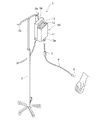
この輸液バッグ加圧装置10は、図1に示すように、点滴を行うための装置である点滴装置1に使用される。点滴装置1は、輸液バッグ加圧装置10と、伸縮自在スタンド2と、輸液バッグ加圧装置10内に挿入される点滴用の輸液が入っている輸液バッグ3と、輸液バッグ3の下端に取り付けられる輸液管4とを有している。なお、輸液管4には、点滴筒5と、輸液針6とが設けられている。また、輸液中に気泡が入るのを防止するために空気抜き手段(図示省略)が設けられている。
【0039】
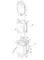
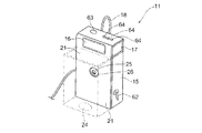
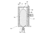
輸液バッグ加圧装置10は、図2に示すように、ホルダ11と、加圧バッグ12から構成されている。ホルダ11は、断面長方形となる四角柱状の上部が開口した輸液バッグ挿入空間13と、この輸液バッグ挿入空間13を形成する箱部14と、後述する加圧ポンプ等が組み込まれている制御部組み込み箱体15と、箱部14の部材と同一部材で形成され表示部16が前面に配置された表示用箱体部17とを備えている。この表示用箱体部17の後方には、伸縮自在スタンド2等に引っ掛けるためのストラップ18(図2では省略)が設置されている。なお、表示部16は、残量表示手段の一部ともなる。
【0040】
輸液バッグ挿入空間13は、この第1の実施の形態では、1,000ml(ミリリットル)としている。これは、輸液バッグ3を500mlのものとしているためである。輸液バッグ3としては、その他に250ml,1,000ml,1,500ml,2,000ml,3,000ml等があり、輸液バッグ挿入空間13の容量をXとし、加圧バッグ12の膨張前の容量をYとし、X−Y=Zとしたとき、輸液バッグ3の初期容量(上述の500ml,250ml等)をWとすると、1.2W≦Z≦2Wとするのが好ましい。この範囲とすると、輸液バッグ3のホルダ11への挿入がスムーズになると共に加圧に要する時間が短くなる。この第1の実施の形態では、X=1,000ml,Y=100ml,W=500mlなので、1.2×500=600≦1,000−100=900≦2×500=1,000となり、好ましいものとなっている。
【0041】
箱部14は、表示用箱体部17の枠も兼ねる平板状の背面体21と、コ字状の前面体22と、箱の底となる底体23とで構成されている。コ字状の前面体22の中央部と背面体21のそれぞれの内側面が、相対向する2つの大面積の内部側壁となり、前面体22の側方の相対向する内側面が、相対向する2つの小面積の内部側壁となる。この第1の実施の形態では、背面体21、前面体22および底体23は、容易には変形しない同一材のアクリル板で構成され、かつ共に茶色系統の透明部材となっている。
【0042】
ここで箱部14を透明部材としたのは、箱部14に挿入された輸液バッグ3の種類を外部から視認できるようにするためであり、茶色系統としたのは、輸液の変質を効果的に防止するためである。なお、背面体21と前面体22とを別体で構成せず一体とし、前面体22となる部分をコ字状に折り曲げ、他端(先端)を背面体21に固定するようにしても良い。
【0043】
底体23は、平板状かつ長方形とされ、図3および図4に示すように、その中央には、輸液バッグ3の口部となる輸液取り出し部3aが貫通する平面楕円状の貫通孔24が設けられている。背面体21には、加圧バッグ12の気体注入部31が嵌合する円形凹部25と、その円形凹部25の中央に配置された挿通孔26とが設けられている。挿通孔26は、加圧バッグ12の気体注入部31の先端が挿通され、制御部組み込み箱体15側にその気体注入部31が飛び出るような貫通穴とされている。
【0044】
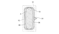
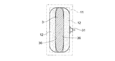
箱部14に挿入される加圧バッグ12は、白色系統の透明材である薄さ0.3mmのポリウレタンフィルムで本体が形成されている。図2、図5および図6に示すように、加圧バッグ12には、気体が注入される入口となる気体注入部31が取り付けられている。また、加圧バッグ12の本体は、加圧バッグ12のホルダ11からの取り出しを容易化するため本体から外方へ突出した指でつかめる把持部32と、輸液バッグ3の挿入を可能とする中央空間33と、その中央空間33を形成するようにホルダ11の4つの内部側壁に沿って配置される2つの大面積部34,34および2つの小面積部35,35と、相対向する2つの大面積の内部側壁に沿って配置され気体の注入によって輸液バッグ12に向かって膨張する膨張可能部36,36(図5の点線で囲まれた部分で大形の長方形となる部分)とを有している。
【0045】
加圧バッグ12は、さらに、大面積部34と小面積部35との間に設けられている1組4つで計8つの切り込み部37と、中央空間33を形成するため両端を接続した接続部38と、その接続部38での接着時のあまり部分となる接続あまり部39と、気体注入部31から一方の膨張可能部36に注入された気体(この実施の形態では空気)を相対向する他方の膨張可能部36に導入する気体案内部40とを有している。また、加圧バッグ12の輸液バッグ3に当接する面であって大面積部34は、梨地面、すなわち、表面に凹凸を設けることで梨地状とされた梨地面(図5の斜線で示す部分)とされている。なお、注入される空気は、図5の矢示で示す方向に拡散していく。
【0046】
気体注入部31は、図4および図6に示すように、大径の平板部41と、先端に向かう程細径となる円錐部42と、先端がわずかに大径となり、加圧ポンプ51(図7参照)からの空気を運んでくる気体注入管43の抜けを防止する先端部44と、気体注入部31の中心を軸方向に貫く注入孔45とを有している。
【0047】
加圧バッグ12は、耐圧60KPa(=438mHg)で、−20℃〜55℃の範囲の温度環境下で使用可能である。また、その最大内部リーク量(漏れ量)は、1.0×10⁻³ml/秒とされている。なお、材料としては、ポリウレタンフィルムの他に塩化ビニールとしても良い。
【0048】
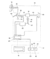
制御部組み込み箱体15は、ABS樹脂材で形成され、図3および図4に示すように、箱部14の後方であって箱部14に固定されるように配置される。この制御部組み込み箱体15は、直方体形状で、その内部には、図7に示すように、加圧手段の一部を構成する加圧ポンプ51と、加圧手段の一部を構成し、加圧ポンプ51を駆動するモータ52と、加圧ポンプ51から加圧バッグ12に供給される気体である空気の圧力(加圧力)を検知する圧力センサとなる半導体圧力センサ53と、加圧ポンプ51からの空気を加圧バッグ12側へ供給すると共に、半導体圧力センサ53へ供給するマニホールド54と、加圧バッグ12へ空気を供給する流路と加圧バッグ12内の空気を排気する流路とを切り替える排気切り替え部55と、モータ52等を制御する制御部となる中央処理制御部(CPU)56と、CPU56やその他の回路素子を載置するメイン基板57とを備えている。なお、CPU56は、加圧手段やポンプ駆動検出手段や残量表示手段の一部ともなる。
【0049】
加圧ポンプ51とマニホールド54の間には、配管チューブとなる気体注入管43の他に、その中間部分にチェック弁58が設けられている。このチェック弁58は、所定の加圧値をオーバーする加圧空気が加圧バッグ12側に流れないようにするものである。また、マニホールド54と半導体圧力センサ53や排気切り替え部55の間にも気体注入管43が配設されている。
【0050】
加圧ポンプ51は、最大吐出量1.5L/分で、最大吐出圧力が26KPaで最大真空到達度が−26KPaとされている。また、定格電圧は直流6Vで、定格電流は0.2Aとされ、設置周囲温度は−20℃〜60℃とされている。モータ52は、100V等の外部交流電源が直流12Vにコンバートされた後、その直流12Vで駆動される。半導体圧力センサ53は、そのハウジングが液晶ポリマで、その圧力レンジが0〜206.8Kpaで、感度は1.46mv/Kpaで、レスポンス時間は1.0msとされている。
【0051】
マニホールド54は、加圧ポンプ51から供給される加圧された空気を加圧バッグ12側に流すと共に、加圧された空気の一部を半導体圧力センサ53へ供給するものである。排気切り替え部55は、その内部に切り替え弁61を有し、加圧スタート兼排気スイッチ62によって加圧バッグ12内の空気を排気口63に排気させたり、マニホールド54からの空気を加圧バッグ12に供給したりする。CPU56は、直流5Vで駆動され、モータ52、半導体圧力センサ53、表示部16等の部品を制御する。なお、加圧スタート兼排気スイッチ62は、図2および図3に示すように、正面から見て右側面下方に設置されている。なお、電源は、外部交流電源とするのではなく、内部に電池を持たせ、その電池を電源とするようにしても良い。
【0052】
表示用箱体部17は、図2、図3および図4に示すように、四角柱を横に倒した形状とされ、材質は箱部14と同一のアクリル板とされている。この表示用箱体部17の前面側と上面側は、先に示した箱部14の背面体21で形成され、全体として逆L字状とされている。そして、表示用箱体部17の前面側中央には表示部16が設けられ、上面側には電源スイッチ63と、複数の切り替えスイッチ64が設けられている。
【0053】
電源スイッチ63や切り替えスイッチ64は、1つのスイッチ用回路基板65に設けられている(図7参照)。図7に示すように、表示部16やスイッチ用回路基板65は、メイン基板57上のCPU56と接続され、CPU56の制御を受ける。なお、表示部16は、液晶からなる表示体で構成されているが、LED(発光ダイオード)、蛍光表示管等他の表示手段を利用しても良い。
【0054】
以上のように構成された輸液バッグ加圧装置10は、次のような性能を有するものとされる。すなわち、最高加圧力は320mmHg(=42.673KPa)、加圧保持最長時間は91時間、装置内最大リーク量は10−3ml/秒とされる。また、加圧値として、最小290mmHgで、最大300mmHgの各値が初期設定値とされている。この最小と最大の各加圧値は、切り替えスイッチ64の中の2つを使用することで変更可能となっている。
【0055】
また、表示部16には、半導体圧力センサ53で検知した加圧力の値、電源のオンオフ(ON−OFF)の表示、加圧中か排気中かの表示、加圧開始からの通算の経過時間(点滴合計時間)の表示、セットした最新の輸液バッグ3を利用開始(加圧開始)してからの経過時間の表示、セットされている輸液バッグ3の種類を示す表示、輸液バッグ3内の輸液の残量表示等がなされる。
【0056】
輸液の残量表示は、次の原理によって測定され、表示される。
【0057】
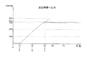
加圧時間と圧力の関係は、図8に示すとおりとなる。すなわち、CPU56からモータ52へ駆動信号が送られることで、加圧ポンプ51が回転し始める。この加圧ポンプ51の回転開始から12秒程度の間は、加圧バッグ12は膨張するものの輸液バッグ3に圧力はかからず、よって加圧値は零状態となる。モータ52の駆動開始後(加圧開始後)12秒経過後に、加圧バッグ12の膨張可能部36は、輸液バッグ3に圧力をかけ始め、駆動開始から50秒程度経過した後に300mmHgとなり、初期設定された最大加圧値となる。半導体圧力センサ53は、加圧バッグ12の圧力を常時検知し、その検知信号をCPU56に送っている。CPU56は、送られてきた信号から最大加圧値となったことを検知すると、モータ52に停止信号を送り、加圧ポンプ51の駆動を停止させる。
【0058】
その状態では、輸液バッグ3が300mmHg程度の圧力で加圧されているため、輸液は所定の速度でゆっくり輸液管4側に流れていく。この流出で輸液バッグ3内の輸液が減少し、輸液バッグ3の大きさが縮むこととなる。この結果、加圧バッグ12内の圧力が徐々に減少していく。そして、初期設定値の最小値である290mmHgとなると、CPU56は、モータ52に駆動信号を送り、加圧ポンプ51は回転し始める。加圧ポンプ51の回転再開は、停止後約30秒程経過してからとなる。すなわち、加圧バッグ12の300mmHgから290mmHgへの圧力減少は、約30秒かけて行われる。
【0059】
加圧ポンプ51が回転を開始すると、数秒後に300mmHgとなる。すると再度、加圧ポンプ51の回転は停止され、加圧値は徐々に減少していく。この繰り返しがなされることで、加圧値は290〜300mmHgの範囲に保たれ安定した点滴がなされる。
【0060】
本発明者による実験によると、加圧ポンプ51の回転開始から輸液バッグ3内の輸液が無くなるまでの加圧ポンプ51の回転数が常に一定であることが確認された。すなわち、加圧ポンプ51の回転開始から輸液が無くなるまでの回転数は、常にN(一定値)であった。また、輸液バッグ3の残量が50%であると、それまでの回転数は0.5Nであり、残量は加圧ポンプ51の回転数に逆比例していた。ただし、これらは温度が一定であることおよび加圧バッグ12のエヤリークが10−3ml/秒以下であることが条件である。このような原理が確認されたことで、本実施の形態では、輸液の残量表示を、この加圧ポンプ51の回転数を検知することで達成している。
【0061】
なお、加圧ポンプ51の回転数は、加圧ポンプ51の駆動時間に比例する。よって、この第1の実施の形態では、加圧ポンプ51の駆動時間をCPU56が算出し、その値から残量を表示している。具体的には、CPU56内またはEEPROMやROM等の記憶手段に、500mlの輸液バッグ3の輸液が無くなるまでの加圧ポンプ51の合計駆動時間であるtN秒を予め保存しておく。そして、その値tN秒と、ポンプ駆動検出手段による検出値であるtX秒、すなわちCPU56によってモータ52の駆動時間が計算されCPU56や所定の記憶手段によって保持されたその合計時間となる積算値tX秒とを利用して、CPU56が残量を算出する。なお、以下では、tNとtXの単位である秒の記載を省略する。
【0062】
たとえば、計算式として〔(tN−tX)÷tN×500ml〕を採用し、絶対的な残量値を表示したり、〔(tN−tX)÷tN〕を採用し、残量の割合を表示したりすることができる。また、加圧ポンプ51の回転数自体を検知し、その検知した回転数と、予め求めておいた輸液が無くなるまでの総回転数とを利用して、残量値を表示したり、残量割合を表示することができる。また、残量の表示の代わりに、使用量の絶対値や使用割合を表示するようにしても良い。
【0063】
合計駆動時間tNや積算値tXを得る際の加圧開始時点としては、図8の0秒(A点)、加圧値が零でなくなり始める時刻である12秒(B点)、設定値の最大値に到達した時刻である50秒(C点)およびB点とC点との間のいずれか1つを採用することができる。この第1の実施の形態では、B点とC点の約中間である30秒(D点)を加圧開始時点として定めている。モータ52の駆動開始後30秒時点を合計駆動時間tNや積算値tXの始点としている。そして、このtNがすべての500mlの輸液バッグ3について常に一定の値となる。
【0064】
なお、輸液バッグ3が500mlのときの合計駆動時間と、輸液バッグ3が1,000mlや2,000ml等他の容量の場合のときの合計駆動時間とは異なる。すなわち加圧ポンプ51の総回転数は輸液バッグ3の容量によって異なる。このため、輸液バッグ加圧装置10を1,000ml用等他の容量用のものにするときには、この合計駆動時間をそれぞれ予め求め、記憶手段に記憶させておくこととなる。この第1の実施の形態の輸液バッグ加圧装置10は、主には500ml用であるが、250mlにも使用できる。このため、250mlのものを使用するときは、切り替えスイッチ64の1つを利用して表示部16に250ml用の輸液バッグ3が入っていることを表示させると共に、合計駆動時間tNは250ml用のものが採用される。
【0065】
図8において一点鎖線で示すものは、組立後のホルダ11の耐圧検査を行う際のもので、この場合は300mmHgを超えて350mmHgまで加圧するが、300mmHgまでとしても良い。この300mmHgは、病人に対して許容される最大加圧値であり、点滴装置1を使用するときは、この300mmHgを超えないようにチェック弁58が機能する。
【0066】
輸液バッグ3を設置し、加圧を開始してからの時間となる点滴時間は、図8のA点(0秒)からの累計時間、すなわち電源スイッチ63をオンし、その後、加圧スタート兼排気スイッチ62を加圧側へ切り替えたときからの経過時間であり、時、分、秒で表示部16に表示される。なお、点滴の合計時間の開始点を、A点ではなく、図8に示すB点やC点としたり、さらにはB点とC点の間のいずれかの時刻としても良い。加圧スタート兼排気スイッチ62を排気側(加圧バッグ12の排気)に切り替えると、切り替えた時点での点滴合計時間をそのまま1分間継続して表示する。
【0067】
この1分間の間に新たな輸液バッグ3を設置し、再度、加圧スタート兼排気スイッチ62を加圧側へ倒すと、先程の表示を継続していた経過時間に加えた通算の累積時間と、今回の新しい輸液バッグ3のみの経過時間の両者を表示部16に表示する。なお、通算の累積時間と最新の輸液バッグ3の点滴時間のいずれか一方のみを表示し、切り替えスイッチ64によってその表示を切り替えることができるようにしても良い。
【0068】
加圧スタート兼排気スイッチ62は、加圧のスタートと加圧バッグ12の排気とを1つのスイッチで行うようにしたものである。図9に示すように、290〜300mmHgとなっている加圧バッグ12内の空気を排気させようとすると、その排気は急激になされる。すなわち、5秒程度で約30mmHgに落ち、その後ゆっくりと圧力がさらに落ちていく。加圧スタート兼排気スイッチ62を排気側に倒すと、急激に排気され、290mmHgとなると、通常ならCPU56はその値を検出し、モータ52に駆動信号を与え、加圧ポンプ51の回転を開始させてしまう。これは輸液バッグ加圧装置10がオン状態であるためである。
【0069】
この輸液バッグ加圧装置10は、装置自体がオン状態で、しかも半導体圧力センサ53が290mmHgを検出しても加圧ポンプ51を回転させないようにしている。これは排気のときの圧力の減少度合い(図9参照)と、点滴を行っている最中の通常の減圧時の圧力の減少度合い(図9参照)に大きな相違があるため、CPU56が両者の違いを区別するようにプログラム化されていることによる。
【0070】
図9に示すように、通常の減圧は、約30秒かけて10mmHg下がる。一方、排気時には、5秒で約270mmHg分、一気に下がる。このため、この実施の形態では、下がり方の中間値となる13〜25mmHg/秒の範囲の中の1つの数値を減少度合いの基準(一定値)として採用する。一方、CPU56は、常時、数m秒〜数10m秒の間の減少度合いを計測し、その値がこの基準(一定値)より大きな値となったことを検知したら、排気であるとCPU56は判断し、加圧値が290mmHgとなっても、CPU56は、モータ52への駆動信号を送出しないようにする。CPU56の計測値が基準(一定値)より小さな値であると、CPU56は通常の減圧であると判断し、290mmHgとなったときに、モータ52へ駆動信号を送出する。
【0071】
この基準(一定値)は、排気の際の減少度合いと通常の減圧の際の減少度合いの間であれば他の値としても良い。ただし、CPU56の判断に誤りを無くすためには、次の値とするのが好ましい。すなわち、排気時の減少度合いをPmmHg/秒とし、通常の減圧時の減少度合いをQmmHg/秒とし、基準値をLとすると、(P−3Q)÷4≦L≦(3P−Q)÷4とするのが好ましい。
【0072】
この第1の実施の形態では、1つの加圧スタート兼排気スイッチ62によって加圧のスタートと加圧バッグ12の排気を実行できる。このため、排気させる以前に、モータ52の駆動や加圧ポンプ51の回転を特別に停止させるように制御させるための排気準備スイッチなどの特別なスイッチを設けることなく、しかも輸液バッグ加圧装置10全体をオフすることなく排気が可能となる。
【0073】
この第1の実施の形態では、加圧スタート兼排気スイッチ62を排気側に切り替えたとき、電源スイッチ63はオンした状態なので、表示部16は表示状態を継続する。しかも、その表示の継続時間を1分間とし、一定時間経過したら表示が消滅するようにしたので、無駄な電力消費が無くなり、液晶の経時的な消耗度合いが無駄に増加しない。一方、1分間の継続表示がなされるので、輸液バッグ3を取り替えるとき、作業者としては、元の輸液バッグ3の残量を確認できたり、最新の加圧値が適切であるかの確認ができたり、点滴合計時間を確認できたりするので、好ましいものとなる。
【0074】
図9において一点鎖線で示すもののうち、ゆっくりした減圧を示すものは、組立後の加圧バッグ12のリーク検査の際のものを示す。また、急激に減圧している一点鎖線は、組立後に行われる耐圧検査後に排気をした場合のときを示す。
【0075】
組立後には、上述したホルダ11の耐圧検査、加圧バッグ12や装置自体のリーク検査、表示部16の表示チェック、操作工程のチェックが行われる。耐圧検査は、300mmHgまたは350mmHgに加圧した際のホルダ11の歪量が5mm以下であることが要請される。また、リーク検査は、300mmHgまたは350mmHgに加圧後のリーク量が10−3ml/秒以下であることが要請される。部品状態での検査後、完成品として再度エアーリークチェックが行われる。完成品としては、さらに電気消費量のチェックや外観チェックが行われる。
【0076】
次に、以上のように構成された輸液バッグ加圧装置10や点滴装置1の動作について、図10から図17までの各図およびその他の図面を参照しながら説明する。
【0077】
まず、輸液バッグ加圧装置10を伸縮自在スタンド2に引っ掛ける。これは、ストラップ18を伸縮自在スタンド2の上端の凹状の引っ掛け部2aに掛けることにより行う。次に、輸液バッグ加圧装置10を電源となる商用交流電源に接続する。
【0078】
次に、電源スイッチ63をオンにする。その後、輸液バッグ3をホルダ11の輸液バッグ挿入空間13に落とし込む。この落とし込みは、加圧バッグ12の中央空間33側の面が梨地とされていることで、スムーズになされる。挿入により、輸液バッグ3は、加圧バッグ12の中央空間33内に入り込むこととなると共に輸液バッグ3の輸液取り出し部(口部)3aが貫通孔24を挿通し、外部に現れる。その状態を図4に示す。
【0079】
次に、輸液管4を輸液取り出し部3aに取り付ける。そして、輸液バッグ3中の空気を抜く。この状態を、側面断面図である図10および平面断面図である図14に示す。この状態では、加圧バッグ12と輸液バッグ3との間には隙間が十分存在している。なお、図4および図10から図17では、輸液バッグ3内の輸液を斜線で示し、加圧バッグ12内の気体となる空気を点々で示すこととする。
【0080】
その後、患者の腕の血管に輸液針6をさす。次に、加圧スタート兼排気スイッチ63を加圧スタート側に倒し、加圧をスタートさせる。この加圧スタートは、そのスイッチ切り換えをCPU56が検知し、モータ52に駆動信号を与えることでなされる。モータ52の駆動開始によって、加圧ポンプ51の回転が開始される。CPU56は、内部のタイマ(時計)によってモータ52の駆動開始時刻を取得し、CPU56はその時刻を記憶手段に記憶させる。また、加圧ポンプ51の回転開始から30秒後の時刻をCPU56は記憶手段に記憶させる。
【0081】
CPU56は、電源スイッチ63がオンされると、表示部16に電源がオンされた旨を表示する「ON」表示を行う。加圧が開始されると、CPU56は、表示部16に加圧中である旨の表示、たとえば「加圧中」を行うと共に、半導体圧力センサ53で検知した圧力を表示させる。また、CPU56は、表示部16にモータ52の駆動開始時刻からの経過時間を表示させると共に1秒経過毎にその表示を1秒加算された表示に切り替えていく。この経過時間が点滴時間となる。
【0082】
CPU56は、さらに表示部16に、使用する輸液バッグ3の種類を示す初期設定値である「500ml」を表示する。なお、上述した各表示および後述する各表示の中のいずれか1つまたは複数を表示しないようにしても良い。
【0083】
加圧が開始されてもしばらくの間は、膨張可能部36は膨張していくが、輸液バッグ3を加圧しないので、圧力値は零のままとなる。約12秒後に膨張可能部36が輸液バッグ3を押し始め、実際の加圧が開始される。そして、圧力値の表示がどんどん大きな値に変化していく。圧力値が300mmHg(=40.0KPa)付近となったときの状態を図11および図15に示す。このとき、加圧バッグ12と輸液バッグ3との隙間はほとんど無い状態となる。
【0084】
この実施の形態では、2つの膨張可能部36,36は、同一容量とされているが、気体注入部31が設けられている側の方が注入側に近いため、早く膨張し大きな容量となる。具体的には、気体注入部32側の膨張可能部3の膨張時の容量を10とすると、もう一方(対向する側)の膨張可能部36の容量は6〜9とされている。しかし、両膨張部36,36の容量を、気体注入部32側を予め大きくし、確実に容量差(10:6〜9)が出るようにしても良い。また、気体の注入差を考慮し、気体注入部32側を予め小さくし、気体注入時の両者の大きさを1:1となるようにしても良い。なお、気体注入時の膨張可能部36,36の大きさを10:6〜9のように、一方を大きくし、他方を小さくすると、小さい側が平板状となり、安定した加圧を得やすいものとなる。
【0085】
CPU56は、半導体圧力センサ53による圧力検知信号を定期的に受け取っている。加圧力が300mmHg(=40.0KPa)になると、CPU56はモータ52に停止信号を送る。CPU56は、モータ52の駆動開始からこの駆動停止までの時間tXを計算し、予め保存しておいて輸液が無くなるまでの合計駆動時間tNとこの時間tXを利用して輸液の残量値または残量割合を表示する。なお、この実施の形態では残量値を表示している。
【0086】
なお、残量表示は、モータ52の駆動開始後、1秒毎等のように短い間隔で残量を計算して表示するようにしても良い。ただし、実際の表示変更は、表示の最小単位が変更される際にその表示を変えることとなる。たとえば、残量表示をmlの単位で表示している場合、「残量490ml」から「残量489ml」への表示変更に当たっては、数回以上の計算を行うこととなっているが、計算された残量が毎回490mlであると、同じ表示となるためその際には表示変更は行わないこととなる。また、tNやtXの単位を秒とせず、分単位として計算するようにしても良い。
【0087】
加圧が停止されると、輸液の減少によって、圧力は減少していく。この圧力減少によって表示部16の圧力値も、「199」「198」「197」「196」のように順次減少していく。CPU56は、その圧力の減少度合いを基準(一定値)である13〜25mmHg/秒の範囲の中の1つの所定値と比較している。輸液の減少による圧力減少度合いは、この基準より小さいので、CPU56は通常の減圧と判断する。このため、圧力が290mmHg(=38.66KPa)になると、CPU56は、モータ52に駆動信号を送信する。これによって加圧ポンプ51の回転が再開され、圧力は上昇する。数秒後には、300mmHgの圧力値となる。
【0088】
CPU56は、圧力(加圧値)が300mmHgとなると、モータ52の再駆動を再度停止させる。CPU56は、モータ52の再駆動から停止までの時間を算出し、先に保存していた累積時間tXにその値を加算し、新たなtXとして再保存する。なお、先に説明したように、時間経過と共にtXを順次更新していくようにしても良い。CPU56は、新たなtXと予め保存しておいたtNとを利用して残量値を求め、表示部16に残量値を表示させる。また、CPU56は、加圧スタート兼排気スイッチ62の加圧側への切り替えからの通算時間(点滴時間)を表示部16に刻々と変化させつつ表示する。
【0089】
以上、このような条件によってモータ52の駆動、停止が繰り返される。すなわち、CPU56は、半導体圧力センサ53からの検知信号を受信し、常時圧力を監視しており、その監視結果に基づいてモータ52へ駆動信号を発信したり、停止信号を発信したりする。これによって加圧バッグ12の圧力は、加圧中、290〜300mmHgの範囲に納められる。
【0090】
図12および図16に、輸液が40%程度利用され、輸液バッグ3内の輸液が略60%程度となった状態を示す。輸液は、加圧バッグ12に押され、輸液バッグ3の上端まで届いている。このため、輸液バッグ加圧装置10を外部から見た場合、輸液バッグ3の残量が100%の場合と変わりない状態として視認することとなる。この状態が維持されるため、外部からの見た目上では残量が確認できない。この点、第1の実施の形態に係る輸液バッグ加圧装置10は、残量表示が簡易かつ確実に行えるため、きわめて有利なものとなる。
【0091】
CPU56の計算に基づいて、輸液バッグ3内の残量が5%または5%以下となると、表示部16にはその際の残量値に加え、残量が無くなったことを示す終了の旨の表示である「終了」または「END」の表示がなされる。このときの状態を図13および図17に示す。作業者は、この表示によって次の輸液バッグ3の準備を開始することができる。なお、終了の旨の表示を、残量値に代えて表示するようにしても良い。
【0092】
作業者は、残量値が「0」となる以前または「0」となったらすぐに加圧スタート兼排気スイッチ62を排気側に切り替える。このスイッチ動作によって、加圧バッグ12内の空気が排出される。CPU56は、その際も圧力の減少度合いを検知し監視している。この急激な排気は、基準値より大きくなるため、CPU56は排気と判断し、圧力値が290mmHgとなった場合にもモータ52を駆動させない。
【0093】
排気の開始後15秒程度たてば、90%以上の排気がなされるので、輸液バッグ3と加圧バッグ12との間に隙間が十分発生し、輸液が5%未満となった輸液バッグ3をホルダ11から容易に取り出すことができる。排気開始から所定の時間、たとえば1分間は表示部16の表示を排気開始時点のままとする。所定時間が経過すると、表示部16の表示は消滅する。新たな輸液バッグ3を使用しないときは、電源スイッチ63をオフにする。
【0094】
同じ患者に対し、点滴を継続させたいときは、電源スイッチ63をオフすることなく、新たな輸液バッグ3をホルダ11にセットする。その後、加圧スタート兼排気スイッチ62を加圧側に切り替えることで加圧がスタートする。その後は、先に示した手順と同様な手順により点滴が行なわれることとなる。
【0095】
電源スイッチ63がオフされることなく、加圧の再開が行われると、CPU56は、その新たな輸液バッグ3の加圧継続時間(点滴時間)を表示すると共に、先程までの輸液バッグ3による点滴時間にこの時間を加えた通算の加圧積算時間(総点滴時間)を表示する。なお、電源スイッチ63をオフさせずに、他の患者に点滴を行う場合は、通算の加圧積算時間は不要となる。このため、そのような場合は、切り替えスイッチ64を利用して、その通算の加圧積算時間を算出しないようにすると共に表示させないようにすることができる。
【0096】
次に、本発明の第2の実施の形態に係る輸液バッグ加圧装置10Aについて、図18を参照しながら説明する。
【0097】
この輸液バッグ加圧装置10Aは、観血的血圧モニタ1Aに使用されるものである。観血的血圧モニタとは、重病の患者に対して行われるもので、動脈にカテーテルを挿入し、血圧をモニタリングするものである。この観血的血圧モニタでは、リアルタイムな血圧が観測されると共に、輸液バッグ加圧装置10Aを使用することで血圧の誤認識をすることなく適切な点滴が可能となる。なお、以下では、第1の実施の形態に係る輸液バッグ加圧装置10と同一部材には同一符号を使用して説明することとする。
【0098】
この観血的血圧モニタ1Aでは、輸液バッグ加圧装置10Aと、輸液管4と、点滴筒5と、トランスデューサ71と、血圧モニタ72と、採血用管材73と、輸液針兼採血針6Aとを有する装置が使用される。この観血的血圧モニタ1Aでは、輸液バッグ加圧装置10A内の加圧バッグ12の加圧力は、290〜300mmHgに設定され、1時間に3mlの割合で患者に輸液を注入する。
【0099】
定常状態では、輸血が動脈内の血液を押しつけながらゆっくり血管内に注入される。この注入に当たって血管内の血液の圧力の変動をトランスデューサ71がとらえ、血圧モニタ72の表示部に血圧波形を表示する。一方、所定時間毎に患者から採血する。
【0100】
採血の際は、採血用管材73を操作し、輸液の血管への注入を阻止すると共に、採血管部73aを介して採血する。輸液の流れが阻止されるため、輸液バッグ3の圧力が減少せず、加圧バッグ12の圧力は維持される。このため、加圧ポンプ51は、駆動されず、停止した状態を維持する。その後、採血を終え、輸液の注入を開始すると、輸液が急激に血管側へ流れていく。このため、輸液バッグ3の輸液が急激に減少し、結果として加圧バッグ12の圧力は急激に減少する。
【0101】
従来の場合、このような圧力の減少に対応しきれなかったが、この圧力減少が生ずると、CPU56は、直ちに加圧ポンプ51の回転を再開し、圧力を上昇させる。このため、血圧を正しく検知できる状態にすみやかに戻ることとなり、医者等の作業者が血圧値を誤認識してしまうという問題が生じなくなる。なお、圧力の減少度合いが排気の場合に比べればかなり小さいものであるため、排気か否かの判断基準となる基準値をそのまま使用することができる。
【0102】
なお、この観血的血圧モニタ1Aの場合、点滴に比べその基準値をより大きめに設定するのが好ましい。すなわち先に示した(P−3Q)÷4≦L≦(3P−Q)÷4となる基準値Lに対して、基準値を10〜30%大きくした値とするのが好ましい。たとえば10%上乗せする場合は、(P−3Q)÷4+(P−Q)÷10≦L≦(3P−Q)÷4+(P−Q)÷10となる。
【0103】
この第2の実施の形態に係る輸液バッグ加圧装置10Aは、輸液バッグ挿入空間13を形成する箱部14が直方体形状で、その前面側を除く周囲三方を平面コ字状のコ字状箱体81が囲むように構成されている。そして、箱部14の前面に表示部16が形成されている。透明な前面を表示部16がさえぎるように構成されているが、その表示部16の面積が小さいので、内部の輸液バッグ3を十分視認することができる。
【0104】
なお、輸液バッグ加圧装置10Aとせず、第1の実施の形態に係る輸液バッグ加圧装置10を用いるようにしても良い。また、表示部16を箱部14ではなく、加圧スタート兼排気スイッチ62が設けられている、コ字状箱体81の前面に設けたり、電源スイッチ63が設けられている面に設けるようにしても良い。
【0105】
以上、本発明の好適な例として各実施の形態を説明したが、本発明の要旨を逸脱しない範囲で種々変更実施可能である。たとえば、本発明の輸液バッグ加圧装置10,10Aは、点滴装置1や観血的血圧モニタ1A以外に輸血、洗浄等、輸液を加圧して送出する必要がある種々の装置に利用することができる。また、輸液としては、水分、電解質、栄養素、血液、血液成分、洗浄液等種々の液体が使用され得る。また、輸液の注入箇所としては、腕以外に足、尻、頭部等種々の人体箇所に使用できる。さらには、人間以外の動物や植物のためにも、本発明の輸液バッグ加圧装置10,10Aを使用することができる。
【0106】
また、輸液バッグ挿入空間13を四角柱状としているが、三角柱状や五角柱状としたり、さらには円柱形状としても良い。円柱形状の輸液バッグ挿入空間13とした場合は、加圧バッグ12は腕に巻くカフ装置のように円筒形状とするのが好ましい。
【0107】
さらに、上述の各実施の形態では、加圧バッグ12の膨張可能部36を相対向する2部分としているが、周囲全体を全て膨張可能部としたり、必要によっては従来のように4つの内部側壁に当接する4つの側面のうち大面積の1つの部分のみに膨張可能部を設けるようにしても良い。また、梨地面を2つの大面積部34,34のみではなく、小面積部35,35の輸液バッグ3の当接面に設けるようにしても良い。また、2つの大面積部34,34のいずれか一方にのみ梨地面を設けるようにしても良い。
【0108】
また、残量表示の工夫や圧力の減少度合いから排気か否かを区別する工夫は、特許文献1、2やその他の従来の自動加圧式の輸液バッグ加圧装置にも適用できる。また、加圧バッグ12の内側面を梨地状とする工夫は、輸液バッグ3を上から落とし込む構造を有する全ての輸液バッグ加圧装置、すなわち手動で加圧する形式の輸液バッグ加圧装置にも適用することができる。さらに、相対向する位置に膨張可能部を設ける工夫は、どのような構造の輸液バッグ加工装置にも適用することができる。
【0109】
また、ホルダ11の箱部14の前面や加圧バッグ12を透明な部材とするのが好ましいが、不透明な部材としても良い。さらに、ホルダ11の材料を容易に変形しない材料としたが、これは、全く変形しないものの他に、わずかに変形するものも採用できることを意味する。上述の各実施の形態では、ホルダ11の材料をアクリル板としたが、ABS樹脂等他の樹脂材としたり、アルミ、ステンレス等の金属材としても良い。
【0110】
さらに、加圧手段としては、モータ52と加圧ポンプ51を採用したが、手動式のゴムフイゴとしても良い。また、加圧バッグ12に注入する気体としては空気の例を示したが、空気以外に、酸素、窒素等他の気体としても良い。また、圧力センサとしては、半導体圧力センサ53を採用したがプルドン管式圧力計やその他の圧力センサを採用しても良い。
【0111】
また、加圧バッグ12としては、製造のしやすさを考慮して、周方向に気体が通り抜けできないように1箇所が完全に遮断された例を示したが、輸液バッグ3を囲む全周に渡って空間が連通する構成としても良い。また、ストラップ18を設けず、代わりに1つまたは複数の引っ掛け部材を輸液バッグ加圧装置10,10Aの背面上部に設けるようにしても良い。さらに、ストラップ18や引っ掛け部材も設けず、載置式や設置式の輸液バッグ加圧装置としても良い。
【0112】
【発明の効果】
本発明の輸液バッグ加圧装置は、輸液バッグを簡単かつスピーディにセットでき、しかも輸液バッグへの加圧の安定化と、排気の高速化を達成できるものとなる。また、他の発明の輸液バッグ加圧装置は、輸液バッグ中の残量を特別な検知装置を付加することなく、簡単な機構で精度良く検出し、表示できるものとなる。
【0113】
さらに、他の発明の輸液バッグ加圧装置は、排気準備スイッチなどの特別なスイッチを設けることなく、しかも装置全体をオフすることなく、排気を可能とすることができる。また、他の発明の輸液バッグ加圧装置は、輸液バッグを簡単かつスピーディにセットできると共に排気の高速化を達成できる。加えて、他の発明の輸液バッグ加圧装置では、輸液バッグを簡単かつスピーディにセットでき、しかも輸液バッグを取り出しても良いか否かの判断が容易となる。
【図面の簡単な説明】
【図1】本発明の第1の実施の形態に係る輸液バッグ加圧装置を使用した点滴装置を示す図である。
【図2】図1の輸液バッグ加圧装置の分解斜視図である。
【図3】図1の輸液バッグ加圧装置の前面側の箱部を取り除いた(一点鎖線で示した)状態の輸液バッグ加圧装置のホルダの斜視図である。
【図4】図1の輸液バッグ加圧装置の要部側面断面図である。
【図5】図1の輸液バッグ加圧装置の加圧バッグの展開図である。
【図6】図1の輸液バッグ加圧装置の加圧バッグを組み立てた状態の図で、(A)は斜視図で、(B)は背面から見た図である。
【図7】図1の輸液バッグ加圧装置の配管および内部回路を示した図である。
【図8】図1の輸液バッグ加圧装置の加圧時間と圧力との関係を示したグラフである。
【図9】図1の輸液バッグ加圧装置の排気時間と圧力との関係を示したグラフである。
【図10】図1の輸液バッグ加圧装置の動作を説明するための図で、加圧開始直前の状態を示す側面断面図である。
【図11】図1の輸液バッグ加圧装置の動作を説明するための図で、加圧の開始後、所定の圧力に到達する直前の状態を示す側面断面図である。
【図12】図1の輸液バッグ加圧装置の動作を説明するための図で、輸液バッグ内の約40%の輸液が使用されたときの状態を示す側面断面図である。
【図13】図1の輸液バッグ加圧装置の動作を説明するための図で、輸液バッグ内の残量が5%となったときの状態を示す側面断面図である。
【図14】図1の輸液バッグ加圧装置の動作を説明するための図で、加圧開始直前の状態を示す平面断面図である。
【図15】図1の輸液バッグ加圧装置の動作を説明するための図で、加圧の開始後、所定の圧力に到達する直前の状態を示す平面断面図である。
【図16】図1の輸液バッグ加圧装置の動作を説明するための図で、輸液バッグ内の約40%の輸液が使用されたときの状態を示す平面断面図である。
【図17】図1の輸液バッグ加圧装置の動作を説明するための図で、輸液バッグ内の残量が5%となったときの状態を示す平面断面図である。
【図18】本発明の第2の実施の形態に係る輸液バッグ加圧装置を使用した観血的血圧モニタを示す図である。
【図19】従来の輸液バッグ加圧装置を示す斜視図である。
【符号の説明】
1 点滴装置
2 伸縮自在スタンド
3 輸液バッグ
4 輸液管
5 点滴筒
6 輸液針
10,10A 輸液バッグ加圧装置
11 ホルダ
12 加圧バッグ
13 輸液バッグ挿入空間
16 表示部(残量表示手段)
18 ストラップ
33 中央空間
36 膨張可能部
51 加圧ポンプ(加圧手段)
52 モータ(加圧手段)
53 半導体圧力センサ(圧力センサ)
56 CPU(制御部、加圧手段、ポンプ駆動検出手段、残量表示手段)
62 加圧スタート兼排気スイッチ
63 電源スイッチ[0001]
TECHNICAL FIELD OF THE INVENTION
The present invention relates to an infusion bag pressurizing device used for infusion, invasive blood pressure monitoring, surgical cleaning, and the like.
[0002]
[Prior art]
In a medical setting, a transfusion in which water, electrolytes, nutrients, and the like are intravenously or orally administered, and a blood transfusion in which all or predetermined components of blood of a healthy person are injected into a patient's blood vessel are performed. . If the infusion rate or blood transfusion is slow, the movement of the liquid is performed by gravity, but if it is necessary to administer a large amount of liquid in a short time, apply pressure to the infusion bag and positively push out the liquid, (Including blood transfusion; the same applies hereinafter) to increase the rate of administration.
[0003]
Such infusion administration includes so-called intravenous infusion for injecting the infusion into a blood vessel of a patient, and infusion in conjunction with an invasive blood pressure monitor for a severely ill patient. The invasive monitor occasionally collects blood while monitoring the blood pressure.
[0004]
As a pressurized infusion device, for example, a portable infusion device as shown in FIG. 19 is known. The
[0005]
Such a manual type portable infusion device is inexpensive and easy to operate, and is therefore used in many medical sites. However, in the case of this type of pressurized infusion device, when the infusion in the
[0006]
For this reason, as shown in FIGS. 5 to 7 of Patent Document 1 (Japanese Patent Application Laid-Open No. 2002-239002), the pressure of the pressurized bag (corresponding to the chamber 101) is detected and the pressurized value is automatically set within a certain range. A technique has been developed in which the number of drops is counted, and the pressure of the pressurized bag is controlled based on the counted value, thereby always obtaining a constant number of drops, that is, a pressing force.
[0007]
Patent Document 2 (Japanese Translation of PCT International Publication No. 2000-507463) discloses that a pressurized space is formed into a shape like water drops, that is, a shape substantially similar to a state in which an infusion bag is deformed by gravity. An invention is disclosed which shortens the time required for the pressure of the bag to reach the pressure value required by the system and prevents the generation of residual liquid in the infusion bag.
[0008]
[Patent Document 1] JP-A-2002-239002 (FIGS. 5 to 7)
[Patent Document 2] Japanese Patent Publication No. 2000-507463 (Abstract)
[0009]
[Problems to be solved by the invention]
The
[0010]
In Patent Literature 1, the shape of the pressure bag is stabilized by fixing a hard plate-shaped member to one inner side surface of the pressure bag, and the infusion bag is uniformly pressed. However, in the invention of Patent Document 1, since the other inner side surface of the pressure bag is made of a flexible material, the shape of the pressure bag is deformed by pressure. For this reason, the problem that the pressure applied to the infusion bag becomes unstable has not been solved yet. Moreover, in the invention of Patent Document 1, when the infusion bag is inserted, there is a problem that the opening above the pressurized bag is insufficient, and it is difficult to install the infusion bag.
[0011]
In addition, in the invention described in
[0012]
Also, in any of the
[0013]
In the case of an automatic dropping type device using gravity, the infusion remaining amount in the infusion bag is readable at a glance because the upper end of the infusion gradually descends as the amount decreases. However, in the case of a pressurized device, since a constant pressure is always applied to the infusion bag, even if the infusion is reduced, the upper end of the infusion does not drop. As a result, the remaining amount of the infusion can be displayed for the first time by detecting the number of drops and estimating the remaining amount from the value. However, the addition of a mechanism for detecting the number of drops causes a new problem that the price of the apparatus becomes high and the difference between the estimated value and the actual value fluctuates greatly (error is large).
[0014]
Further, in the automatic pressurizing devices described in
[0015]
In order to prevent this problem, in an automatic pressurizing apparatus as described in
[0016]
Further, Patent Literature 1 discloses a technique in which a control unit with a monitor is fixedly arranged on the front surface of a pressure bag means. However, this control unit is mounted on the deformable front side, which is a major factor in that the pressurization is not uniform. In addition, the values displayed on the monitor unit are the pressure in the pressurized bag, the dropping rate of the infusion, the dropping amount of the infusion, the remaining amount of the infusion in the infusion bag, and the infusion time. ) Is not operating (exhaust state) is not displayed. For this reason, it is difficult to determine whether it is good or bad to take out the infusion bag.
[0017]
The present invention has been made in order to solve the above-mentioned problems, and an infusion bag that can easily and speedily set an infusion bag, and that can stabilize the pressure applied to the infusion bag and achieve high-speed exhaustion. It is an object to provide a pressurizing device. Another object of the present invention is to provide an infusion bag pressurizing device capable of accurately detecting and displaying the remaining amount in an infusion bag with a simple mechanism without adding a special detection device.
[0018]
Still another object of the present invention is to provide an infusion bag pressurizing device capable of exhausting without providing a special switch such as an exhaust preparation switch, and without turning off the entire device. Another object of the present invention is to provide an infusion bag pressurizing device capable of setting an infusion bag easily and speedily and achieving high-speed exhaust. In addition, another object of the present invention is to provide an infusion bag pressurizing device that can easily and speedily set an infusion bag and easily determine whether or not to take out an infusion bag.
[0019]
[Means for Solving the Problems]
In order to achieve the above object, the infusion bag pressurizing device of the present invention has a rectangular column-shaped infusion bag insertion space having an open upper portion and a rectangular cross section, and a holder that is not easily deformed, and an infusion bag insertion. An inflation that is arranged along the inner side wall of the holder so as to form a central space that allows it, and a portion along two opposing large-area inner side walls of the four inner side walls is inflatable by gas injection. A pressurizing bag that is a possible portion, a pressurizing unit that supplies gas to the inflatable portion of the pressurizing bag and pressurizes the infusion bag, and a pressure sensor that detects a pressing force by the pressurizing unit. I have.
[0020]
ADVANTAGE OF THE INVENTION According to the infusion bag pressurizing apparatus of this invention, the infusion bag can be set easily and speedily by the device of a holder and a pressurization bag, moreover, the stabilization of the pressure to an infusion bag and the high-speed exhaust are achieved. be able to.
[0021]
An infusion bag pressurizing device of another invention has an infusion bag insertion space, a holder that is not easily deformed, and an infusion bag insertion space that is disposed in the infusion bag insertion space so as to be able to face the inserted infusion bag, and is provided on an inner side wall of the holder. A pressurized bag that is disposed along and has an inflatable portion that can be inflated by gas injection, and a pressurizing pump that serves as pressurizing means for supplying gas to the inflatable portion of the pressurized bag and pressurizing the infusion bag. Pump drive detecting means for detecting the number of rotations or the rotation time of the pressurizing pump, and storing in advance the number of rotations or the time of rotation of the pressurizing pump from the start of the driving of the pressurizing pump until the infusion in the infusion bag becomes empty. The remaining amount of the infusion bag is calculated using the value and the value detected by the pump drive detecting means, the remaining amount is displayed on a display unit, and the pressure sensor detects the pressing force by the pressurizing means. And It is.
[0022]
ADVANTAGE OF THE INVENTION According to the infusion bag pressurizing device of this invention, the remaining amount in an infusion bag can be accurately detected and displayed by a simple mechanism without adding a special detection device by utilizing the characteristics of the pressurizing pump. It becomes.
[0023]
Further, the infusion bag pressurizing device according to another invention has an infusion bag insertion space, a holder that is not easily deformed, and a holder that is disposed in the infusion bag insertion space so as to be able to face the inserted infusion bag and has an interior inside the holder. A pressurization bag disposed along the side wall and having an inflatable portion that can be inflated by injecting a gas, pressurizing means for supplying gas to the inflatable portion of the pressurized bag, and pressurizing the infusion bag; A pressure sensor for detecting the pressing force by the means, and a stop signal is sent to the pressurizing means when the value of the pressure sensor exceeds a predetermined value, and a drive signal is sent to the pressurizing means when the value of the pressure sensor falls below another predetermined value. And a control unit for detecting the degree of decrease in the value of the pressure sensor and transmitting a drive signal when the value of the pressure sensor falls below another predetermined value when the value exceeds a predetermined value. .
[0024]
In the infusion bag pressurizing device of the present invention, exhaust detection is performed by utilizing the fact that there is a large difference between the degree of pressure decrease in the case of exhaust and the degree of decrease in normal drive pressure. The exhaust can be performed without providing a special switch and without turning off the entire apparatus.
[0025]
An infusion bag pressurizing device according to another invention has an infusion bag insertion space with an open upper part, a holder that is not easily deformed, and an inner side wall of the holder that is arranged so as to surround the inserted infusion bag. A pressurized bag which is disposed along the inflatable portion and which is inflatable by injecting a gas, and in which all or a part of a surface of the inflatable portion which comes into contact with the infusion bag is matted, It has a pressurizing means for supplying gas to the inflatable portion and pressurizing the infusion bag, and a pressure sensor for detecting a pressing force by the pressurizing means.
[0026]
ADVANTAGE OF THE INVENTION According to the infusion bag pressurizing apparatus of this invention, by devising a holder and a pressurization bag, an infusion bag can be set simply and speedily, and high-speed exhaust can be achieved.
[0027]
In addition, in addition to the infusion bag pressurizing device of each of the above-mentioned inventions, another invention starts any time between the time when pressure starts to be applied to the infusion bag and the time when the desired pressure is reached. A display unit is provided for displaying the total time of pressurization by the pressurizing means calculated as time.
[0028]
With this configuration, 10 seconds from the start of pressurization until the pressure is actually applied to the infusion bag is not reliably included in the total pressurization time, and the total pressurization time is in line with the actual condition. .
[0029]
If the time when pressure starts to be applied to the infusion bag is set as the calculation start time, the total time from the time when the amount of drip or the like actually starts to be calculated is small, but the correct pressurization total time is calculated. Time is gained. On the other hand, if the time at which the pressure on the infusion bag reaches a desired value is set as the calculation start time, the total time during which the desired infusion volume (infusion volume) is maintained can be calculated. The total time during which the infusion of the infusion was reliably performed can be obtained. In addition, if an intermediate value between the time when the pressure starts to be applied to the infusion bag and the time when the pressure reaches a desired value, for example, is used as the calculation start time, the total infusion ratio that is more accurately proportional to the desired infusion amount is increased. You can get the total time.
[0030]
In addition, the infusion bag pressurizing device of another invention has an infusion formed such that a rectangular column having a rectangular cross section has an open upper part and a part of the lower part communicates with the outside so as to allow the mouth of the infusion bag to be inserted therethrough. A holder that has a bag insertion space, is not easily deformed, and has a transparent front surface; and a holder that is disposed in the infusion bag insertion space so as to be able to face the infusion bag to be inserted and is disposed along the inner side wall of the holder. A pressurizing bag having an inflatable portion that can be inflated by gas injection, at least a front surface portion of which is transparent, a pressurizing unit that supplies gas to the inflatable portion of the pressurizing bag and pressurizes the infusion bag, and a holder. And a display unit for displaying whether the state is a pressurized state or an exhausted state.
[0031]
ADVANTAGE OF THE INVENTION According to the infusion bag pressurizing apparatus of this invention, an infusion bag can be set simply and speedily by the ingenuity of a holder and a display part, and it becomes easy to determine whether it is OK to take out an infusion bag. In addition, since the display unit is fixed to the rigid holder, the display unit is not obstructed at the time of pressurization, and is easy to handle and easy for the operator to handle.
[0032]
Further, in another invention, in addition to the infusion bag pressurizing device of the above-mentioned invention, a display portion is provided above the back of the infusion bag insertion space and at a position which is not hidden by the inserted infusion bag.
[0033]
When this configuration is adopted, the display unit becomes very easy to see. Further, in the present invention, the display unit does not hinder the determination of the presence or absence of the infusion bag or the confirmation of the contents of the infusion bag.
[0034]
In addition, in addition to the infusion bag pressurizing device of each of the above-mentioned inventions, Z is a value obtained by subtracting the capacity of the infusion bag before inflation in the infusion bag insertion space from the capacity of the infusion bag insertion space as Z, Assuming that the initial capacity of the bag is W, 1.2W ≦ Z ≦ 2W.
[0035]
When the value obtained by subtracting the capacity of the infusion bag before inflation in the infusion bag insertion space from the capacity of the infusion bag insertion space from the capacity of the infusion bag insertion space of the holder is Z, and when the initial volume of the infusion bag is W, Z is 1 When the pressure is set to 0.2 W or more, a sufficient space for inserting the infusion bag can be obtained even after the pressurized bag is inserted into the infusion bag insertion space. For this reason, the insertion of the infusion bag into the holder becomes smooth. Further, when the above-mentioned value Z is set to 2 W or less when the initial volume of the infusion bag is W, the gap between the infusion bag and the pressurized bag after insertion becomes small, and until the predetermined pressurized value is reached. The time required for pressurization does not significantly increase.
[0036]
When the value Z is not set to 1.2 W ≦ Z ≦ 2 W, but set to 1.4 W ≦ Z ≦ 1.8 W, it is possible to prevent an increase in pressurization time while maintaining the smoothness of insertion of the infusion bag. Can be further achieved, which is more preferable.
[0037]
BEST MODE FOR CARRYING OUT THE INVENTION
Hereinafter, embodiments of the present invention will be described with reference to the drawings. First, an infusion bag pressurizing device according to the first embodiment will be described with reference to FIGS.
[0038]
As shown in FIG. 1, the infusion
[0039]
The infusion
[0040]
The infusion
[0041]
The
[0042]
Here, the
[0043]
The
[0044]
The main body of the
[0045]
The
[0046]
As shown in FIGS. 4 and 6, the
[0047]
The
[0048]
The control unit built-in
[0049]
A
[0050]
The
[0051]
The manifold 54 allows the pressurized air supplied from the pressurizing
[0052]
As shown in FIGS. 2, 3 and 4, the
[0053]
The
[0054]
The infusion
[0055]
In addition, the
[0056]
The indication of the remaining amount of infusion is measured and displayed according to the following principle.
[0057]
The relationship between the pressurizing time and the pressure is as shown in FIG. That is, when a drive signal is sent from the
[0058]
In this state, the
[0059]
When the pressurizing
[0060]
According to an experiment by the inventor, it was confirmed that the number of rotations of the pressurizing
[0061]
The rotation speed of the
[0062]
For example, [(tN−tX) ÷ tN × 500 ml] is used as a calculation formula to display an absolute remaining amount, or [(tN−tX) ÷ tN] is used to display the ratio of the remaining amount. Or you can. In addition, the number of rotations of the pressurizing
[0063]
The pressurization start time when obtaining the total drive time tN and the integrated value tX is 0 seconds (point A) in FIG. 8, 12 seconds (point B) at which the pressurization value starts to become non-zero, and the set value. Either 50 seconds (point C), which is the time when the maximum value is reached, or any one between point B and point C can be adopted. In the first embodiment, 30 seconds (point D), which is about halfway between the points B and C, is determined as the pressurization start time. 30 seconds after the start of driving of the motor 52 is set as the starting point of the total driving time tN and the integrated value tX. This tN is always a constant value for all the 500
[0064]
The total drive time when the
[0065]
In FIG. 8, what is indicated by a one-dot chain line is when a pressure resistance test is performed on the
[0066]
The infusion time, which is the time from the installation of the
[0067]
When a
[0068]
The pressurization start /
[0069]
The infusion
[0070]
As shown in FIG. 9, the normal reduced pressure drops by 10 mmHg in about 30 seconds. On the other hand, at the time of exhaustion, the pressure drops at a stretch of about 270 mmHg in 5 seconds. For this reason, in this embodiment, one numerical value in the range of 13 to 25 mmHg / sec, which is an intermediate value in the descending direction, is adopted as a reference (constant value) of the degree of decrease. On the other hand, the
[0071]
This reference (constant value) may be another value as long as it is between the degree of decrease during exhaust and the degree of decrease during normal depressurization. However, in order to eliminate an error in the judgment of the
[0072]
In the first embodiment, the start of pressurization and the evacuation of the
[0073]
In the first embodiment, when the pressurization start /
[0074]
In FIG. 9, one indicated by a dashed line and one indicating a slow decompression is the one at the time of a leak test of the
[0075]
After assembling, the above-described pressure test of the
[0076]
Next, the operation of the infusion
[0077]
First, the infusion
[0078]
Next, the
[0079]
Next, the
[0080]
Thereafter, the infusion needle 6 is pointed at the blood vessel of the patient's arm. Next, the pressurization start /
[0081]
When the
[0082]
The
[0083]
Even if the pressurization is started, the
[0084]
In this embodiment, the two
[0085]
The
[0086]
It should be noted that the remaining amount display may calculate and display the remaining amount at short intervals, such as once every second, after the driving of the motor 52 is started. However, the actual display change changes the display when the minimum unit of the display is changed. For example, when the remaining amount is displayed in the unit of ml, when the display is changed from “490 ml” to “489 ml”, the calculation is performed several times or more. If the remaining amount is 490 ml each time, the display is the same, so that the display is not changed at that time. Further, the unit of tN or tX may be calculated in minutes instead of seconds.
[0087]
When the pressurization is stopped, the pressure decreases due to the decrease in infusion. Due to this pressure decrease, the pressure value of the
[0088]
When the pressure (pressurized value) reaches 300 mmHg, the
[0089]
As described above, the driving and stopping of the motor 52 are repeated under such conditions. That is, the
[0090]
FIGS. 12 and 16 show a state in which about 40% of the infusion is used and about 60% of the infusion in the
[0091]
Based on the calculation by the
[0092]
The operator switches the pressurization start /
[0093]
About 15 seconds after the start of the evacuation, 90% or more of the evacuation is performed. Therefore, a sufficient gap is generated between the
[0094]
When it is desired to continue the infusion for the same patient, a
[0095]
When the pressurization is restarted without turning off the
[0096]
Next, an infusion
[0097]
This infusion
[0098]
In the invasive
[0099]
In the steady state, the transfusion is slowly infused into the blood vessel, pressing on the blood in the artery. During this injection, a change in the pressure of the blood in the blood vessel is detected by the
[0100]
At the time of blood collection, the
[0101]
In the conventional case, such a decrease in the pressure could not be coped with. However, when the decrease in the pressure occurs, the
[0102]
In the case of the invasive
[0103]
In a transfusion
[0104]
The infusion
[0105]
Although the embodiments have been described as preferred examples of the present invention, various modifications can be made without departing from the scope of the present invention. For example, the infusion
[0106]
In addition, although the infusion
[0107]
Further, in each of the above-described embodiments, the
[0108]
In addition, the device for displaying the remaining amount and the device for discriminating whether or not the gas is exhausted from the degree of decrease in the pressure can be applied to
[0109]
Further, the front surface of the
[0110]
Further, the motor 52 and the pressurizing
[0111]
In addition, as for the
[0112]
【The invention's effect】
ADVANTAGE OF THE INVENTION The infusion bag pressurizing apparatus of this invention can set an infusion bag easily and speedily, and also can achieve the stabilization of the pressure to an infusion bag, and the high-speed exhaust. In addition, the infusion bag pressurizing device of another invention can accurately detect and display the remaining amount in the infusion bag with a simple mechanism without adding a special detection device.
[0113]
Further, the infusion bag pressurizing device according to another invention can be evacuated without providing a special switch such as an exhaust preparation switch and without turning off the entire device. Further, the infusion bag pressurizing device of another invention can set the infusion bag simply and speedily and can achieve high-speed exhaust. In addition, in the infusion bag pressurizing device of another invention, the infusion bag can be set easily and quickly, and it is easy to determine whether or not the infusion bag can be taken out.
[Brief description of the drawings]
FIG. 1 is a diagram showing an infusion device using an infusion bag pressurizing device according to a first embodiment of the present invention.
FIG. 2 is an exploded perspective view of the infusion bag pressurizing device of FIG.
FIG. 3 is a perspective view of a holder of the infusion bag pressurizing device in a state where a box on the front side of the infusion bag pressurizing device of FIG. 1 is removed (indicated by a dashed line).
FIG. 4 is a side sectional view of a main part of the infusion bag pressurizing device of FIG. 1;
FIG. 5 is a development view of a pressure bag of the infusion bag pressure device of FIG. 1;
FIGS. 6A and 6B are views showing a state in which the pressurizing bag of the infusion bag pressurizing device of FIG. 1 is assembled, wherein FIG. 6A is a perspective view and FIG.
FIG. 7 is a diagram showing a pipe and an internal circuit of the infusion bag pressurizing device of FIG. 1;
8 is a graph showing the relationship between the pressurizing time and the pressure of the infusion bag pressurizing device of FIG.
9 is a graph showing the relationship between the evacuation time and the pressure of the infusion bag pressurizing device of FIG.
FIG. 10 is a side sectional view showing a state immediately before the start of pressurization, for explaining the operation of the infusion bag pressurizing device in FIG. 1;
11 is a view for explaining the operation of the infusion bag pressurizing device in FIG. 1, and is a side sectional view showing a state immediately after the start of pressurization and reaching a predetermined pressure.
12 is a view for explaining the operation of the infusion bag pressurizing device in FIG. 1, and is a side sectional view showing a state when about 40% of the infusion in the infusion bag is used.
13 is a view for explaining the operation of the infusion bag pressurizing device in FIG. 1, and is a side sectional view showing a state when the remaining amount in the infusion bag becomes 5%.
14 is a view for explaining the operation of the infusion bag pressurizing device of FIG. 1, and is a plan sectional view showing a state immediately before the start of pressurization.
15 is a view for explaining the operation of the infusion bag pressurizing device of FIG. 1, and is a plan sectional view showing a state immediately after the start of pressurization and reaching a predetermined pressure.
16 is a view for explaining the operation of the infusion bag pressurizing device in FIG. 1, and is a plan sectional view showing a state when about 40% of the infusion in the infusion bag is used.
17 is a view for explaining the operation of the infusion bag pressurizing device in FIG. 1, and is a plan sectional view showing a state when the remaining amount in the infusion bag becomes 5%.
FIG. 18 is a view showing an invasive blood pressure monitor using the infusion bag pressurizing device according to the second embodiment of the present invention.
FIG. 19 is a perspective view showing a conventional infusion bag pressurizing device.
[Explanation of symbols]
1 Infusion device
2 Telescopic stand
3 infusion bag
4 Infusion tube
5 drip tube
6 Infusion needle
10,10A Infusion bag pressurizing device
11 Holder
12 Pressure bag
13 Infusion bag insertion space
16 display part (remaining amount display means)
18 Strap
33 Central Space
36 Expandable part
51 Pressurizing pump (pressurizing means)
52 motor (pressurizing means)
53 Semiconductor pressure sensor (pressure sensor)
56 CPU (control unit, pressurizing means, pump drive detecting means, remaining amount displaying means)
62 Pressurization start and exhaust switch
63 Power switch
Claims (8)
輸液バッグの挿入を可能とする中央空間を形成するように上記ホルダの内部側壁に沿って配置されると共に、4つの内部側壁のうち相対向する2つの大面積の内部側壁に沿う部分が気体の注入によって膨張可能な膨張可能部とされている加圧バッグと、
上記加圧バッグの上記膨張可能部に気体を供給し、上記輸液バッグを加圧する加圧手段と、
上記加圧手段による加圧力を検出する圧力センサと、
を有することを特徴とする輸液バッグ加圧装置。A holder that has a square column-shaped infusion bag insertion space with an upper opening and a rectangular cross section, and that is not easily deformed,
It is arranged along the inner side wall of the holder so as to form a central space that allows insertion of the infusion bag, and a portion along two opposing large-area inner side walls of the four inner side walls is formed of gas. A pressurized bag that is an inflatable portion that can be inflated by injection,
Pressurizing means for supplying gas to the inflatable portion of the pressurizing bag and pressurizing the infusion bag,
A pressure sensor for detecting the pressing force by the pressurizing means,
An infusion bag pressurizing device comprising:
挿入される輸液バッグに対向可能に上記輸液バッグ挿入空間内に配置されると共に上記ホルダの内部側壁に沿って配置され、かつ気体の注入によって膨張可能な膨張可能部を備える加圧バッグと、
上記加圧バッグの上記膨張可能部に気体を供給し、上記輸液バッグを加圧する加圧手段となる加圧ポンプと、
上記加圧ポンプの回転数または回転時間を検出するポンプ駆動検出手段と、
上記加圧ポンプの駆動開始から上記輸液バッグ内の輸液が空になるまでの上記加圧ポンプの回転数または回転時間を予め保存し、その値と上記ポンプ駆動検出手段による検出値とを利用して上記輸液バッグの残量を計算し、その値を表示部に表示する残量表示手段と、
上記加圧手段による加圧力を検出する圧力センサと、
を有することを特徴とする輸液バッグ加圧装置。A holder that has an infusion bag insertion space and does not easily deform,
A pressurized bag that is disposed in the infusion bag insertion space so as to face the infusion bag to be inserted and that is arranged along the inner side wall of the holder, and that has an inflatable portion that can be inflated by gas injection.
A pressure pump that supplies gas to the inflatable portion of the pressure bag and serves as pressure means for pressurizing the infusion bag,
Pump drive detecting means for detecting the number of rotations or the rotation time of the pressurizing pump,
The rotation number or rotation time of the pressure pump from the start of driving the pressure pump to the time when the infusion in the infusion bag becomes empty is stored in advance, and the value and the detection value of the pump drive detection unit are used. Calculating the remaining amount of the infusion bag, and displaying the value on a display unit;
A pressure sensor for detecting the pressing force by the pressurizing means,
An infusion bag pressurizing device comprising:
挿入される輸液バッグに対向可能に上記輸液バッグ挿入空間内に配置されると共に上記ホルダの内部側壁に沿って配置され、かつ気体の注入によって膨張可能な膨張可能部を備える加圧バッグと、
上記加圧バッグの上記膨張可能部に気体を供給し、上記輸液バッグを加圧する加圧手段と、
上記加圧手段による加圧力を検出する圧力センサと、
上記圧力センサの値が所定値を越えたら上記加圧手段に停止信号を送出し、上記圧力センサの値が他の所定値を下回ったら上記加圧手段に駆動信号を送出すると共に上記圧力センサの値の減少度合いを検出し一定値を越えていたときには上記圧力センサの値が他の所定値を下回ったとしても上記駆動信号を送出しないようにした制御部と、
を有することを特徴とする輸液バッグ加圧装置。A holder that has an infusion bag insertion space and does not easily deform,
A pressurized bag that is disposed in the infusion bag insertion space so as to face the infusion bag to be inserted and that is arranged along the inner side wall of the holder, and that has an inflatable portion that can be inflated by gas injection.
Pressurizing means for supplying gas to the inflatable portion of the pressurizing bag and pressurizing the infusion bag,
A pressure sensor for detecting the pressing force by the pressurizing means,
When the value of the pressure sensor exceeds a predetermined value, a stop signal is sent to the pressurizing means, and when the value of the pressure sensor falls below another predetermined value, a drive signal is sent to the pressurizing means, and A control unit configured to not transmit the drive signal even when the value of the pressure sensor falls below another predetermined value when the degree of decrease of the value is detected and exceeds a certain value;
An infusion bag pressurizing device comprising:
挿入される輸液バッグを囲むように配置されると共に上記ホルダの内部側壁に沿って配置され、気体の注入によって膨張可能な膨張可能部を備え、この膨張可能部の上記輸液バッグに当接する面の全部又は一部が梨地状とされた加圧バッグと、
上記加圧バッグの上記膨張可能部に気体を供給し、上記輸液バッグを加圧する加圧手段と、
上記加圧手段による加圧力を検出する圧力センサと、
を有することを特徴とする輸液バッグ加圧装置。A holder that has an infusion bag insertion space with an open top and is not easily deformed;
An inflatable portion is provided so as to surround the infusion bag to be inserted and is arranged along the inner side wall of the holder, and is provided with an inflatable portion which can be inflated by gas injection. A pressurized bag in which all or a part has a satin shape,
Pressurizing means for supplying gas to the inflatable portion of the pressurizing bag and pressurizing the infusion bag,
A pressure sensor for detecting the pressing force by the pressurizing means,
An infusion bag pressurizing device comprising:
上記加圧バッグの上記膨張可能部に気体を供給し、上記輸液バッグを加圧する加圧手段と、
上記ホルダに固定され、加圧状態か排気状態かを表示する表示部と、
を有することを特徴とする輸液バッグ加圧装置。A rectangular column-shaped upper part having a rectangular cross section is opened, and a part of the lower part has an infusion bag insertion space formed so as to communicate with the outside so that the mouth of the infusion bag can be inserted, and it is not easily deformed. A holder having a transparent front surface, and an inflation disposed in the infusion bag insertion space so as to be opposed to the infusion bag to be inserted, along the inner side wall of the holder, and inflatable by gas injection. A pressurized bag including a possible portion, at least a front portion of which is transparent,
Pressurizing means for supplying gas to the inflatable portion of the pressurizing bag and pressurizing the infusion bag,
A display unit fixed to the holder, for displaying whether the pressure state or the exhaust state,
An infusion bag pressurizing device comprising:
Priority Applications (1)
| Application Number | Priority Date | Filing Date | Title |
|---|---|---|---|
| JP2003024551A JP2004230032A (en) | 2003-01-31 | 2003-01-31 | Infusion bag pressurizing apparatus |
Applications Claiming Priority (1)
| Application Number | Priority Date | Filing Date | Title |
|---|---|---|---|
| JP2003024551A JP2004230032A (en) | 2003-01-31 | 2003-01-31 | Infusion bag pressurizing apparatus |
Publications (1)
| Publication Number | Publication Date |
|---|---|
| JP2004230032A true JP2004230032A (en) | 2004-08-19 |
Family
ID=32953055
Family Applications (1)
| Application Number | Title | Priority Date | Filing Date |
|---|---|---|---|
| JP2003024551A Pending JP2004230032A (en) | 2003-01-31 | 2003-01-31 | Infusion bag pressurizing apparatus |
Country Status (1)
| Country | Link |
|---|---|
| JP (1) | JP2004230032A (en) |
Cited By (14)
| Publication number | Priority date | Publication date | Assignee | Title |
|---|---|---|---|---|
| JPS6358515A (en) * | 1986-08-29 | 1988-03-14 | Canon Inc | Power supply device |
| JP2010005075A (en) * | 2008-06-26 | 2010-01-14 | Pacific Hospital Supply Co Ltd | Apparatus for pressing infusion automatically |
| JP2011024817A (en) * | 2009-07-27 | 2011-02-10 | Nipro Corp | Tube nutrition injecting device |
| JP2013504381A (en) * | 2009-09-09 | 2013-02-07 | アビオメド インコーポレイテッド | Method for simultaneously delivering fluid to a dual lumen catheter with a single fluid source |
| CN104014031A (en) * | 2014-05-28 | 2014-09-03 | 苏州瓦屋物联网科技有限公司 | Time-prompt drip monitoring device based on pressure detection |
| CN104014055A (en) * | 2014-05-28 | 2014-09-03 | 苏州瓦屋物联网科技有限公司 | Pressure-detection-based drip control system with flow rate indication |
| JP2014236925A (en) * | 2013-06-10 | 2014-12-18 | 独立行政法人国立循環器病研究センター | Multi-purpose pressurizing bag |
| CN109200392A (en) * | 2018-10-31 | 2019-01-15 | 北京工商大学 | Liquid residue and the device being automatically turned off in a kind of automatic detection infusion bag |
| JP2020526239A (en) * | 2017-05-26 | 2020-08-31 | アンジオドロイド エス.アール.エル. | Methods for preparing and supplying doses of gas contrast agents for angiography and devices that implement such methods. |
| CN112439104A (en) * | 2020-11-24 | 2021-03-05 | 重庆市机电设计研究院 | Emergency treatment method for gravity-free infusion |
| KR20210132261A (en) * | 2020-04-24 | 2021-11-04 | 성균관대학교산학협력단 | Detachable liquid level sensing device for infusion solution pack and casing device for the infusion solution pack using the device |
| JP6980359B1 (en) * | 2021-03-10 | 2021-12-15 | 入江工研株式会社 | Pressurized container |
| CN114425112A (en) * | 2020-10-29 | 2022-05-03 | 安徽省立医院(中国科学技术大学附属第一医院) | Continuous slow-release administration indwelling tube with puncture sheath and controller |
| WO2022163115A1 (en) * | 2021-02-01 | 2022-08-04 | 株式会社村田製作所 | Pressurization device |
-
2003
- 2003-01-31 JP JP2003024551A patent/JP2004230032A/en active Pending
Cited By (19)
| Publication number | Priority date | Publication date | Assignee | Title |
|---|---|---|---|---|
| JPS6358515A (en) * | 1986-08-29 | 1988-03-14 | Canon Inc | Power supply device |
| JP2010005075A (en) * | 2008-06-26 | 2010-01-14 | Pacific Hospital Supply Co Ltd | Apparatus for pressing infusion automatically |
| JP2011024817A (en) * | 2009-07-27 | 2011-02-10 | Nipro Corp | Tube nutrition injecting device |
| JP2013504381A (en) * | 2009-09-09 | 2013-02-07 | アビオメド インコーポレイテッド | Method for simultaneously delivering fluid to a dual lumen catheter with a single fluid source |
| US9278189B2 (en) | 2009-09-09 | 2016-03-08 | Abiomed, Inc. | Apparatus for simultaneously delivering fluid to a dual lumen catheter with a single fluid source |
| JP2014236925A (en) * | 2013-06-10 | 2014-12-18 | 独立行政法人国立循環器病研究センター | Multi-purpose pressurizing bag |
| CN104014031A (en) * | 2014-05-28 | 2014-09-03 | 苏州瓦屋物联网科技有限公司 | Time-prompt drip monitoring device based on pressure detection |
| CN104014055A (en) * | 2014-05-28 | 2014-09-03 | 苏州瓦屋物联网科技有限公司 | Pressure-detection-based drip control system with flow rate indication |
| JP7140404B2 (en) | 2017-05-26 | 2022-09-21 | アンジオドロイド エス.アール.エル. | Computer program for causing a computer to execute a method for preparing and delivering a dose of gaseous contrast agent for angiography and a device for implementing such method |
| JP2020526239A (en) * | 2017-05-26 | 2020-08-31 | アンジオドロイド エス.アール.エル. | Methods for preparing and supplying doses of gas contrast agents for angiography and devices that implement such methods. |
| CN109200392A (en) * | 2018-10-31 | 2019-01-15 | 北京工商大学 | Liquid residue and the device being automatically turned off in a kind of automatic detection infusion bag |
| KR20210132261A (en) * | 2020-04-24 | 2021-11-04 | 성균관대학교산학협력단 | Detachable liquid level sensing device for infusion solution pack and casing device for the infusion solution pack using the device |
| KR102353719B1 (en) * | 2020-04-24 | 2022-01-21 | 성균관대학교산학협력단 | Detachable liquid level sensing device for infusion solution pack and casing device for the infusion solution pack using the device |
| CN114425112A (en) * | 2020-10-29 | 2022-05-03 | 安徽省立医院(中国科学技术大学附属第一医院) | Continuous slow-release administration indwelling tube with puncture sheath and controller |
| CN112439104A (en) * | 2020-11-24 | 2021-03-05 | 重庆市机电设计研究院 | Emergency treatment method for gravity-free infusion |
| WO2022163115A1 (en) * | 2021-02-01 | 2022-08-04 | 株式会社村田製作所 | Pressurization device |
| JP7439961B2 (en) | 2021-02-01 | 2024-02-28 | 株式会社村田製作所 | Pressure device |
| JP6980359B1 (en) * | 2021-03-10 | 2021-12-15 | 入江工研株式会社 | Pressurized container |
| WO2022190260A1 (en) * | 2021-03-10 | 2022-09-15 | 入江工研株式会社 | Pressure container |
Similar Documents
| Publication | Publication Date | Title |
|---|---|---|
| JP2004230032A (en) | Infusion bag pressurizing apparatus | |
| US9782115B2 (en) | System and method for monitoring bladder and abdominal pressures, and bladder function recovery system | |
| US8734354B2 (en) | Sphygmomanometer | |
| US9486574B2 (en) | Modular skin-adherable system for medical fluid delivery | |
| CN109640902B (en) | Systems and methods for controlling operation of a reduced pressure treatment system to detect leaks | |
| US6358237B1 (en) | Methods and apparatus for delivering fluids to a patient | |
| JP5208753B2 (en) | INJECTION SYSTEM, METHOD, AND COMPUTER-READABLE RECORDING MEDIUM FOR CONTROLLING EXPANSION MEDIUM SUPPLY TO ENDOSCOPE DEVICE | |
| US8425426B2 (en) | Tourniquet apparatus for measuring limb occlusion pressure | |
| JP4823443B2 (en) | Implantable artificial pancreas device | |
| US20030048185A1 (en) | Apparatus and process for infusion monitoring | |
| AU740070B2 (en) | External blood pressure sensor apparatus and method | |
| JP2824063B2 (en) | Retrograde perfusion and retrograde infusion control device, system and method | |
| JP2008511378A (en) | Portable infusion device | |
| US20240000668A1 (en) | Disposable Tubing Set for an Enteral Feeding System | |
| CN108310597A (en) | A kind of balloon expandable system | |
| WO2006054720A1 (en) | Automatic peritoneal dialyzer and method of drainage control therefor | |
| WO2020167737A1 (en) | System and method for monitoring filling status of a vaporizer reservoir in an anesthetic vaporizer system | |
| JP2006026270A (en) | Medical liquid injector | |
| JP5608346B2 (en) | Tube feeding device | |
| IL120693A (en) | Flow indicators for ambulatory infusion | |
| WO2021150999A1 (en) | Devices and methods for managing chest or wound drainage | |
| JPH0647006A (en) | Pressure cuff device | |
| JP3194471U (en) | Medical tube feeding device | |
| JP2023528279A (en) | Mobile Negative Pressure Wound Therapy Device | |
| KR200368270Y1 (en) | Portable infusion pump |