JP2004226509A - Electronic flash device and camera - Google Patents
Electronic flash device and camera Download PDFInfo
- Publication number
- JP2004226509A JP2004226509A JP2003011752A JP2003011752A JP2004226509A JP 2004226509 A JP2004226509 A JP 2004226509A JP 2003011752 A JP2003011752 A JP 2003011752A JP 2003011752 A JP2003011752 A JP 2003011752A JP 2004226509 A JP2004226509 A JP 2004226509A
- Authority
- JP
- Japan
- Prior art keywords
- light
- led
- strobe device
- light source
- lens
- Prior art date
- Legal status (The legal status is an assumption and is not a legal conclusion. Google has not performed a legal analysis and makes no representation as to the accuracy of the status listed.)
- Pending
Links
Images


Abstract
Description
【0001】
【発明の属する技術分野】
本発明はストロボ装置及びカメラに係り、特にストロボ光源に発光ダイオード(LED)を用いたストロボ装置及びカメラに関する。
【0002】
【従来の技術】
一般にカメラのストロボ装置は、光源としてキセノン管を利用している。しかし、光源にキセノン管を用いたストロボ装置は、数ミリ秒程度の瞬間光しか発光できないため、スローシャッタでのストロボ撮影ができないという欠点があった。また、キセノン管は昼光色に近い分光特性をもっているため、朝方や夕方に逆光補正を目的としたストロボ撮影を行うと、不自然な色合いの写真となるという欠点があった。
【0003】
そこで、このようなキセノン管を光源に用いたストロボ装置の欠点を解消すべく、光源にLEDを用いたストロボ装置が提案されている(たとえば、特許文献1)。
【0004】
【特許文献1】
特開2002−116481号公報
【0005】
【発明が解決しようとする課題】
しかしながら、LEDは点光源であるため、キセノン管のストロボ装置に比べて発光面積が小さく、狭い範囲しか光を照射できないという欠点がある。
【0006】
本発明はこのような事情に鑑みてなされたもので、光源にLEDを用いて広範囲に光を照射することができるストロボ装置及びカメラを提供することを目的とする。
【0007】
【課題を解決するための手段】
請求項1に係る発明は、前記目的を達成するために、発光ダイオードにより照明光を放出するLED光源と、該LED光源から放出された光を前方に向けて反射するリフレクタとを有する発光部と、前記発光部の前方に配置され、該発光部から放出される光を前方に拡大投光するレンズと、を備えたことを特徴とするストロボ装置を提供する。
【0008】
本発明によれば、発光部の前方に光を拡大するレンズを配置することにより、点光源として発光される発光ダイオードからの光を拡大して照射することができる。これにより、点光源で指向性の強い発光ダイオードを光源に用いた場合であっても、広範囲に光を当てることができる。
【0009】
また、請求項2に係る発明は、前記目的を達成するために、前記LED光源と前記レンズの間に前記LED光源から放出する光を拡散させる光学部材を配置したことを特徴とする請求項1に記載のストロボ装置を提供する。
【0010】
本発明によれば、LED光源から放出された光を光学部材で拡散することにより、発光部の発光面積を拡げることができる。
【0011】
また、請求項3に係る発明は、前記目的を達成するために、前記光学部材は、前記LED光源から放出する光を拡散させるとともに、所定の色温度に変換することを特徴とする請求項2に記載のストロボ装置を提供する。
【0012】
また、本発明によれば、LED光源から放出される光を光学部材によって所定の色温度に整えることができる。
【0013】
また、請求項4に係る発明は、前記目的を達成するために、前記発光部と前記レンズとを光軸方向に相対移動させる移動手段を備え、該移動手段で前記発光部と前記レンズとを光軸方向に相対移動させることにより、前記レンズから出射される光の照射角を変化させることを特徴とする請求項1、2又は3に記載のストロボ装置を提供する。
【0014】
本発明によれば、移動手段で発光部とレンズとを光軸方向に相対移動させることにより、レンズから出射される光の照射角を変化させることができる。
【0015】
また、請求項5に係る発明は、前記目的を達成するために、請求項1、2、3又は4に記載のストロボ装置をカメラ本体に内蔵したことを特徴とするカメラを提供する。
【0016】
【発明の実施の形態】
以下、添付図面に従って本発明に係るストロボ装置及びカメラの好ましい実施の形態について詳説する。
【0017】
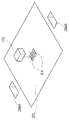
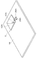
図1は、本発明に係るストロボ装置が組み込まれたカメラの一実施形態を示す正面斜視図である。
【0018】
このカメラ1は、CCDを用いて被写体の光学像をデジタル信号に変換し、記録メディアに記録するデジタルカメラであり、そのカメラボディ(カメラ本体)2の正面には、撮影レンズ3、ファインダ窓4、ストロボ装置5、ストロボ調光窓6等が設けられており、上面にはレリーズボタン7、電源スイッチ8等が設けられている。また、図示はしていないが、カメラボディ2の背面には、ファインダ接眼部、液晶モニタ、各種操作ボタン類などが設けられている。
【0019】
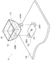
図2は、図1に示すカメラ1のカメラボディ2に内蔵されたストロボ装置5の構成を示す斜視図である。
【0020】
同図に示すように、ストロボ装置5は、チップ(型)LED10、リフレクタ12及び拡散板14からなる発光部9と、その発光部9からの光を前方に向けて拡大投光する凹レンズ16とで構成され、回路基板18(たとえば、プリント基板)に取り付けられている。
【0021】
回路基板18には、回路部品(たとえば、ストロボ装置5のチップLED10を発光制御するためのストロボ回路等)が実装されている。この回路基板18には、金メッキが付着された実装ランド20が設けられており、ストロボ装置5は、この実装ランド20に取り付けられている。
【0022】
光源であるチップLED10は、表面実装が可能であって、高輝度で白色発光する。このチップLED10には、2つの電極パッド(図示せず)が設けられており、それらの電極パットが、図3に示すように、回路基板18の実装ランド20に設けられたパッド24、24に半田ペースト等の導電性接着剤で接合されている。これにより、チップLED10が実装ランド20に固着されるとともに、回路基板18に実装されたストロボ回路に電気的に接続される。なお、実装ランド20のパッド24、24は、金メッキとは絶縁されている。また、チップLED10を回路基板18に実装する方法は上述の場合に限らない。
【0023】
リフレクタ12は、先端部に向かって拡大する矩形の筒状に形成されており、実装ランド20に固着されたチップLED10の周囲を囲むようにして回路基板18に取り付けられることにより、チップLED10から放出された光を前方に向けて反射する。このリフレクタ12の基端部外周には、図4に示すように、一対の爪26A、26Bが設けられており、この爪26A、26Bを回路基板18に形成された取付孔28A、28Bに嵌めこむことにより、リフレクタ12が回路基板18に固定される。
【0024】
拡散板14は、リフレクタ12内に取り付けられており、チップLED10から放出される光を拡散するとともに、所定の色温度に変換する。この拡散板14は、リフレクタ12の断面形状に合致して形成されており、リフレクタ12の内壁面に密着して固定されている。したがって、チップLED10から放出される光は、すべて拡散板14を透過する。
【0025】
凹レンズ16は、リフレクタ12の先端部に取り付けられており、拡散板14を介して放出されるチップLED10からの光を前方に向けて拡大投光する。この凹レンズ16は、リフレクタ12の先端開口部の形状に合致して形成されており、リフレクタ12の先端開口部を塞ぐようにして取り付けられている。
【0026】
前記のごとく構成された本実施の形態のストロボ装置5の作用は次のとおりである。
【0027】
図5に示すように、光源としてのチップLED10のLED(チップ)から放出された光は、まず、拡散板14を透過することで、拡散されるとともに所定の色温度に変換される。そして、この拡散板14を透過した光が、凹レンズ16を透過することで、前方に向けて放射状に拡大投光される。これにより、点光源として発光し、指向性の強いLEDからの光を広範囲に照射することができる。
【0028】
また、本実施の形態のストロボ装置5によれば、チップLED10から側面方向に放出された光が、リフレクタ12によって前方に反射されるとともに、チップLED10から背面方向に放出された光が、実装ランド20に付着された金メッキによって前方に向けて反射される。これにより、チップLED10から側面方向及び背面方向に放出された光も前方への照明光として有効に利用することができる。
【0029】
また、チップLED10等を回路基板18に実装することにより、部品点数を削減でき、製造コストの低減を図ることができる。
【0030】
なお、本実施の形態では、1つの白色発光のチップLED10をストロボ装置5の光源として使用したが、1つだけでなく複数の白色発光のチップLEDを回路基板18の実装ランド20に実装して光源として使用してもよい。
【0031】
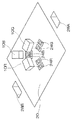
また、ストロボ装置5の光源として白色発光のチップLED10を用いるのではなく、異なる発光色のチップLED、たとえば赤色発光、緑色発光、青色発光のチップLEDを使用し、これらの光を混ぜ合わせて白色の照明光を放射するようにしてもよい。この場合、図6に示すように、赤色発光、緑色発光、青色発光の各チップLED10R、10G、10Bを回路基板18の実装ランド20に放射状に配置することが好ましい。すなわち、図2に示した一対のパッド24と同様の3対のパッド24R、24G、24Bを回路基板18の実装ランド20に放射状に設け、各対のパッド24R、24G、24Bにそれぞれ赤色発光のチップLED10R、緑色発光のチップLED10G、青色発光のチップLED10Bを固着する。これにより、各チップLED10R、10G、10Bから放出する光を効率よく混ぜることができる。
【0032】
また、本実施の形態では、白色の照明光を放射する場合について説明したが、白色以外の色の照明光を放射させるようにしてもよく、その場合にはその色に応じた発光色のチップLEDを用いればよい。
【0033】
さらに、本実施の形態では、実装ランド20の表面に金メッキを付着させ、チップLED10から背面方向に放出された光を前方に反射させるようにしたが、実装ランド20の表面は光を反射させる効果があれば金メッキ以外の材料で形成してもよい。
【0034】
また、本実施の形態では、ストロボ装置5の光源として表面実装型のチップLED10を使用したが、光源として使用するLEDの形態はこれに限らず、図7に示すように、リード端子が設けられているLEDランプ10Aを使用することもできる。この場合、リフレクタ12Aには、前面のみが開口しているものを使用することができる。
【0035】
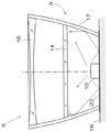
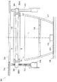
図8は本発明に係るストロボ装置の第2の実施の形態の構成を示す縦断面図である。
【0036】
同図に示すように、本実施の形態のストロボ装置30は、上述した第1の実施の形態のストロボ装置5において、光源の前方に配置された凹レンズ16を光軸に沿って前後移動自在に保持したもので、これにより、ストロボ装置から照射される光の照射角度を可変する。なお、上述した実施の形態のストロボ装置5と同じ構成部材には、同一符号を付して、その説明は省略する。
【0037】
図8に示すように、チップLED10、リフレクタ12及び拡散板14からなる発光部9の前方には、レンズ枠32に保持された凹レンズ16が配置されており、その前方には透明なカバーガラス34が配置されている。カバーガラス34は、カメラボディの外装2Aに嵌めこまれている。
【0038】
凹レンズ16を保持するレンズ枠32は、その外周部にガイド部36とナット部38が一体成形されている。
【0039】
ガイド部36には凹レンズ16の光軸Lに沿ってガイド穴36Aが形成されており、このガイド穴36Aには、光軸Lに沿って配設されたガイド棒40が挿通されている。ガイド棒40は、カメラボディ内に配設された図示しないフレームに固定されており、このガイド棒40に沿ってガイド部36が摺動することにより、凹レンズ16が光軸Lに沿って発光部9の前方を前後移動する。
【0040】
一方、ナット部38には凹レンズ16の光軸Lに沿ってネジ穴38Aが形成されており、このネジ穴38Aには、光軸Lに沿って配設されたネジ棒42が螺合されている。ネジ棒42は、カメラボディ内に配設されたモータ44の出力軸に連結されており、このモータ44を駆動することにより回転する。そして、このネジ棒42が回転することにより、ナット部38がネジ棒42に沿って移動し、これにより、凹レンズ16が光軸Lに沿って前後移動する。
【0041】
なお、このネジ棒42を回転駆動するモータ44は、デジタルカメラ1を統括・制御する制御部(CPU)によって駆動が制御されており、撮影レンズ3のズーミングに連動して駆動される。すなわち、凹レンズ16を介して照射される光の照射角が、撮影レンズ3の画角に応じて変化するように駆動が制御される。
【0042】
以上のように構成された本実施の形態のストロボ装置30によれば、発光部9の前方に配置された凹レンズ16を光軸Lに沿って前後移動させることにより、凹レンズ16を介して照射される光の照射角度を撮影レンズ3の画角に合わせて変えることができる。これにより、光源としてのチップLED10から照射される光を効率よく利用することができる。
【0043】
なお、本実施の形態では、発光部9を固定し、この固定された発光部9に対して凹レンズ16を前後移動させているが、逆でもよい。すなわち、凹レンズ16を固定し、この固定された凹レンズ16に対して発光部9を凹レンズ16の光軸Lに対して前後移動させてもよい。
【0044】
また、上述した第1及び第2の実施の形態では、本発明にかかるストロボ装置をデジタルカメラに組み込んだ例で説明したが、フィルムを用いた銀塩カメラに用いることもできる。
【0045】
また、本実施の形態では、本発明に係るストロボ装置をカメラ本体に組み込んだ場合を例に説明したが、独立して構成してもよい(いわゆる、外付けタイプのストロボ装置)。
【0046】
【発明の効果】
以上説明したように、本発明によれば、発光部の前方に光を拡大するレンズを配置することにより、点光源として発光される発光ダイオードからの光を拡大して照射することができる。これにより、点光源で指向性の強い発光ダイオードを光源に用いた場合であっても、広範囲に光を当てることができる。
【図面の簡単な説明】
【図1】本発明に係るストロボ装置が組み込まれたカメラの一実施形態を示す正面斜視図
【図2】第1の実施の形態のストロボ装置の構成を示す斜視図
【図3】チップLEDの回路基板への取付構造を示す斜視図
【図4】リフレクタの回路基板への取付構造を示す斜視図
【図5】第1の実施の形態のストロボ装置の構成を示す縦断面図
【図6】RGB3色のチップLEDの回路基板への取付構造を示す斜視図
【図7】LEDランプの回路基板への取付構造を示す斜視図
【図8】第2の実施の形態のストロボ装置の縦断面図
【符号の説明】
1…カメラ、2…カメラボディ、3…撮影レンズ、4…ファインダ窓、5…ストロボ装置、6…ストロボ調光窓、7…レリーズボタン、8…電源スイッチ、9…発光部、10、10R、10G、10B…チップLED、10A…ランプLED、12、12A…リフレクタ、14…拡散板、16…凹レンズ、18…回路基板、20…実装ランド、24、24R、24G、24B…パッド、26A、26B…爪、28A、28B…取付穴、30…ストロボ装置、32…レンズ枠、34…カバーガラス、36…ガイド部、36A…ガイド穴、38…ナット部、38A…ネジ穴、40…ガイド棒、42…ネジ棒、44…モータ[0001]
BACKGROUND OF THE INVENTION
The present invention relates to a strobe device and a camera, and more particularly to a strobe device and a camera using a light emitting diode (LED) as a strobe light source.
[0002]
[Prior art]
Generally, a camera strobe device uses a xenon tube as a light source. However, a strobe device using a xenon tube as a light source can emit only instantaneous light of about several milliseconds, and thus has a drawback that it cannot perform strobe photography with a slow shutter. Also, since the xenon tube has a spectral characteristic close to daylight color, there is a drawback in that if the flash photography is performed in the morning or evening for the purpose of correcting backlighting, the photograph has an unnatural color.
[0003]
Therefore, a strobe device using an LED as a light source has been proposed in order to eliminate the disadvantages of the strobe device using such a xenon tube as a light source (for example, Patent Document 1).
[0004]
[Patent Document 1]
Japanese Patent Laid-Open No. 2002-116481
[Problems to be solved by the invention]
However, since the LED is a point light source, it has a drawback that it has a light emitting area smaller than that of a xenon tube strobe device and can irradiate light only in a narrow range.
[0006]
The present invention has been made in view of such circumstances, and an object thereof is to provide a strobe device and a camera capable of irradiating light over a wide range using an LED as a light source.
[0007]
[Means for Solving the Problems]
In order to achieve the above object, the invention according to claim 1 includes: a light emitting unit including an LED light source that emits illumination light by a light emitting diode; and a reflector that reflects light emitted from the LED light source forward. A strobe device comprising: a lens disposed in front of the light emitting unit and enlarging and projecting light emitted from the light emitting unit forward.
[0008]
According to the present invention, it is possible to magnify and irradiate light from a light emitting diode that emits light as a point light source by disposing a lens that expands light in front of the light emitting unit. Thereby, even if it is a case where a light emitting diode with strong directivity with a point light source is used for a light source, light can be irradiated in a wide range.
[0009]
The invention according to
[0010]
ADVANTAGE OF THE INVENTION According to this invention, the light emission area of a light emission part can be expanded by diffusing the light discharge | released from the LED light source with an optical member.
[0011]
According to a third aspect of the present invention, in order to achieve the object, the optical member diffuses light emitted from the LED light source and converts the light into a predetermined color temperature. The strobe device described in 1. is provided.
[0012]
Further, according to the present invention, the light emitted from the LED light source can be adjusted to a predetermined color temperature by the optical member.
[0013]
According to a fourth aspect of the present invention, in order to achieve the object, the light emitting unit and the lens are provided with moving means for moving the light emitting unit and the lens in the optical axis direction, and the light emitting unit and the lens are moved by the moving means. The strobe device according to claim 1, wherein the irradiation angle of the light emitted from the lens is changed by relative movement in the optical axis direction.
[0014]
According to the present invention, the irradiation angle of the light emitted from the lens can be changed by relatively moving the light emitting unit and the lens in the optical axis direction by the moving means.
[0015]
According to a fifth aspect of the present invention, there is provided a camera characterized in that the strobe device according to the first, second, third or fourth aspect is incorporated in a camera body in order to achieve the object.
[0016]
DETAILED DESCRIPTION OF THE INVENTION
Hereinafter, preferred embodiments of a strobe device and a camera according to the present invention will be described in detail with reference to the accompanying drawings.
[0017]
FIG. 1 is a front perspective view showing an embodiment of a camera incorporating a strobe device according to the present invention.
[0018]
The camera 1 is a digital camera that converts an optical image of a subject into a digital signal using a CCD and records the digital signal on a recording medium. A photographing
[0019]
FIG. 2 is a perspective view showing a configuration of the
[0020]
As shown in the figure, the
[0021]
Circuit parts (for example, a strobe circuit for controlling light emission of the
[0022]
The
[0023]
The
[0024]
The
[0025]
The
[0026]
The operation of the
[0027]
As shown in FIG. 5, the light emitted from the LED (chip) of the
[0028]
Further, according to the
[0029]
Further, by mounting the
[0030]
In this embodiment, one white light emitting
[0031]
Further, instead of using the white light emitting
[0032]
In the present embodiment, the case where white illumination light is emitted has been described. However, illumination light of a color other than white may be emitted, and in that case, a chip of an emission color corresponding to that color. An LED may be used.
[0033]
Further, in the present embodiment, gold plating is attached to the surface of the mounting
[0034]
Further, in the present embodiment, the surface-mounted
[0035]
FIG. 8 is a longitudinal sectional view showing the configuration of the second embodiment of the strobe device according to the present invention.
[0036]
As shown in the figure, the
[0037]
As shown in FIG. 8, a
[0038]
The
[0039]
A
[0040]
On the other hand, a
[0041]
The
[0042]
According to the
[0043]
In the present embodiment, the
[0044]
In the first and second embodiments described above, an example in which the strobe device according to the present invention is incorporated in a digital camera has been described, but it can also be used in a silver salt camera using a film.
[0045]
In this embodiment, the case where the strobe device according to the present invention is incorporated in the camera body has been described as an example. However, the strobe device may be configured independently (a so-called external strobe device).
[0046]
【The invention's effect】
As described above, according to the present invention, it is possible to magnify and irradiate light from a light emitting diode that emits light as a point light source by disposing a lens that expands light in front of the light emitting unit. Thereby, even if it is a case where the light emitting diode with strong directivity with a point light source is used for a light source, light can be irradiated in a wide range.
[Brief description of the drawings]
FIG. 1 is a front perspective view showing an embodiment of a camera incorporating a strobe device according to the present invention. FIG. 2 is a perspective view showing a configuration of a strobe device according to a first embodiment. FIG. 4 is a perspective view showing a structure for attaching a reflector to a circuit board. FIG. 5 is a longitudinal sectional view showing a structure of a strobe device according to the first embodiment. FIG. 7 is a perspective view showing a structure for mounting an LED lamp of RGB three colors on a circuit board. FIG. 7 is a perspective view showing a structure for mounting an LED lamp on a circuit board. FIG. 8 is a longitudinal sectional view of a strobe device according to a second embodiment. [Explanation of symbols]
DESCRIPTION OF SYMBOLS 1 ... Camera, 2 ... Camera body, 3 ... Shooting lens, 4 ... Finder window, 5 ... Strobe device, 6 ... Strobe dimming window, 7 ... Release button, 8 ... Power switch, 9 ... Light emission part, 10, 10R, 10G, 10B ... Chip LED, 10A ... Lamp LED, 12, 12A ... Reflector, 14 ... Diffuser, 16 ... Concave lens, 18 ... Circuit board, 20 ... Mounting land, 24, 24R, 24G, 24B ... Pad, 26A, 26B ... Claw, 28A, 28B ... Mounting hole, 30 ... Strobe device, 32 ... Lens frame, 34 ... Cover glass, 36 ... Guide portion, 36A ... Guide hole, 38 ... Nut portion, 38A ... Screw hole, 40 ... Guide rod, 42 ... Screw rod, 44 ... Motor
Claims (5)
前記発光部の前方に配置され、該発光部から放出される光を前方に拡大投光するレンズと、
を備えたことを特徴とするストロボ装置。A light emitting unit including an LED light source that emits illumination light by a light emitting diode, and a reflector that reflects light emitted from the LED light source forward;
A lens that is disposed in front of the light-emitting unit and that projects the light emitted from the light-emitting unit to the front,
A strobe device characterized by comprising:
Priority Applications (3)
| Application Number | Priority Date | Filing Date | Title |
|---|---|---|---|
| JP2003011752A JP2004226509A (en) | 2003-01-21 | 2003-01-21 | Electronic flash device and camera |
| US10/759,421 US7734168B2 (en) | 2003-01-21 | 2004-01-20 | Lighting apparatus, electronic flash apparatus and camera |
| US11/227,256 US7224894B2 (en) | 2003-01-21 | 2005-09-16 | Lighting apparatus, electronic flash apparatus and camera |
Applications Claiming Priority (1)
| Application Number | Priority Date | Filing Date | Title |
|---|---|---|---|
| JP2003011752A JP2004226509A (en) | 2003-01-21 | 2003-01-21 | Electronic flash device and camera |
Publications (1)
| Publication Number | Publication Date |
|---|---|
| JP2004226509A true JP2004226509A (en) | 2004-08-12 |
Family
ID=32900559
Family Applications (1)
| Application Number | Title | Priority Date | Filing Date |
|---|---|---|---|
| JP2003011752A Pending JP2004226509A (en) | 2003-01-21 | 2003-01-21 | Electronic flash device and camera |
Country Status (1)
| Country | Link |
|---|---|
| JP (1) | JP2004226509A (en) |
Cited By (3)
| Publication number | Priority date | Publication date | Assignee | Title |
|---|---|---|---|---|
| WO2006049104A1 (en) * | 2004-11-01 | 2006-05-11 | Nikon Corporation | Light emitting device |
| JP2007140114A (en) * | 2005-11-18 | 2007-06-07 | Kyocera Corp | Portable electronic equipment |
| KR101061097B1 (en) * | 2009-11-27 | 2011-08-31 | 주식회사 세코닉스 | Light condensing lens for LED with bead layer |
-
2003
- 2003-01-21 JP JP2003011752A patent/JP2004226509A/en active Pending
Cited By (4)
| Publication number | Priority date | Publication date | Assignee | Title |
|---|---|---|---|---|
| WO2006049104A1 (en) * | 2004-11-01 | 2006-05-11 | Nikon Corporation | Light emitting device |
| US7588339B2 (en) | 2004-11-01 | 2009-09-15 | Nikon Corporation | Light emitting device |
| JP2007140114A (en) * | 2005-11-18 | 2007-06-07 | Kyocera Corp | Portable electronic equipment |
| KR101061097B1 (en) * | 2009-11-27 | 2011-08-31 | 주식회사 세코닉스 | Light condensing lens for LED with bead layer |
Similar Documents
| Publication | Publication Date | Title |
|---|---|---|
| US7224894B2 (en) | Lighting apparatus, electronic flash apparatus and camera | |
| CN101645442B (en) | Light-emitting diode devices | |
| US7551848B2 (en) | Photographic light system, imaging device and method for providing different types of photographic light using a single multifunctional light module | |
| JP2006114911A (en) | Electronic flash for forming flashlight having wavelength spectrum in the visible range and the infrared range using fluorescent substance, apparatus and method of imaging | |
| KR101138327B1 (en) | Lighting device | |
| JP4168617B2 (en) | Flash device for imaging device, imaging device with flash device, and imaging method | |
| JP2005210723A (en) | Composite illuminating device of led and strobe | |
| JP2004349628A (en) | Semiconductor light emitting device and lighting device for photographing using it | |
| JP2005114924A (en) | Illuminator for photography | |
| JP2006278889A (en) | Semiconductor lamp and electronic apparatus | |
| JP2008084600A (en) | Light emitting device, and cellular phone with camera equipped with same | |
| JP2010015700A (en) | Lighting system, and image capturing apparatus | |
| JP5061572B2 (en) | Illumination device and imaging device | |
| JP2007017986A (en) | Device and method for producing output light having a wavelength spectrum in the infrared wavelength range and the visible wavelength range | |
| JP2004226509A (en) | Electronic flash device and camera | |
| JP2003337372A (en) | Illuminator for underwater photography with digital camera | |
| JPH10274799A (en) | Ring light stroboscope provided with rotary light shielding plate for light balance and light quantity control | |
| JP2006010745A (en) | Illuminator | |
| JP2006004632A (en) | Lighting device | |
| JP4623951B2 (en) | Lighting equipment | |
| JP2006162717A (en) | Camera equipped with illuminator | |
| JP2003121905A (en) | Photographic device with red-eye effect reducing function | |
| JP2005294193A (en) | Lighting apparatus for photography | |
| JP2005091582A (en) | Illuminating device | |
| KR100996729B1 (en) | Ring light |
Legal Events
| Date | Code | Title | Description |
|---|---|---|---|
| A621 | Written request for application examination |
Free format text: JAPANESE INTERMEDIATE CODE: A621 Effective date: 20050329 |
|
| A977 | Report on retrieval |
Free format text: JAPANESE INTERMEDIATE CODE: A971007 Effective date: 20060726 |
|
| A131 | Notification of reasons for refusal |
Free format text: JAPANESE INTERMEDIATE CODE: A131 Effective date: 20060731 |
|
| A521 | Written amendment |
Free format text: JAPANESE INTERMEDIATE CODE: A523 Effective date: 20060927 |
|
| A711 | Notification of change in applicant |
Free format text: JAPANESE INTERMEDIATE CODE: A712 Effective date: 20061211 |
|
| A131 | Notification of reasons for refusal |
Free format text: JAPANESE INTERMEDIATE CODE: A131 Effective date: 20070302 |
|
| A521 | Written amendment |
Free format text: JAPANESE INTERMEDIATE CODE: A523 Effective date: 20070427 |
|
| A02 | Decision of refusal |
Free format text: JAPANESE INTERMEDIATE CODE: A02 Effective date: 20080715 |
|
| A521 | Written amendment |
Free format text: JAPANESE INTERMEDIATE CODE: A523 Effective date: 20080826 |
|
| A911 | Transfer of reconsideration by examiner before appeal (zenchi) |
Free format text: JAPANESE INTERMEDIATE CODE: A911 Effective date: 20081016 |
|
| A912 | Removal of reconsideration by examiner before appeal (zenchi) |
Free format text: JAPANESE INTERMEDIATE CODE: A912 Effective date: 20081219 |