JP2004225084A - Automobile knuckle - Google Patents
Automobile knuckle Download PDFInfo
- Publication number
- JP2004225084A JP2004225084A JP2003012414A JP2003012414A JP2004225084A JP 2004225084 A JP2004225084 A JP 2004225084A JP 2003012414 A JP2003012414 A JP 2003012414A JP 2003012414 A JP2003012414 A JP 2003012414A JP 2004225084 A JP2004225084 A JP 2004225084A
- Authority
- JP
- Japan
- Prior art keywords
- knuckle
- carbon
- automobile
- metal
- aluminum
- Prior art date
- Legal status (The legal status is an assumption and is not a legal conclusion. Google has not performed a legal analysis and makes no representation as to the accuracy of the status listed.)
- Pending
Links
Images


Classifications
-
- B—PERFORMING OPERATIONS; TRANSPORTING
- B82—NANOTECHNOLOGY
- B82Y—SPECIFIC USES OR APPLICATIONS OF NANOSTRUCTURES; MEASUREMENT OR ANALYSIS OF NANOSTRUCTURES; MANUFACTURE OR TREATMENT OF NANOSTRUCTURES
- B82Y30/00—Nanotechnology for materials or surface science, e.g. nanocomposites
Abstract
Description
【0001】
【発明の属する技術分野】
本発明は、自動車用ナックルに関するものである。
【0002】
【背景技術】
自動車用ナックルは、いわゆる車輪軸受部材であり、一般的な材質として鋳鉄が用いられている。自動車部品の軽量化が求められる中、アルミニウム製の自動車用ナックルがある(特許文献1)。
【0003】
【特許文献1】
特開平8−324450号公報(第1−4頁、図1)
【0004】
【発明が解決しようとする課題】
しかしながら、従来の軽量化したアルミニウム製のナックルにおいては、アルミニウム自体が鉄に比べて剛性、特に靭性が低く、そのため補強のためのリブ構造や肉盛りなどが必要であった。これらリブ構造や肉盛りなどは、自動車用ナックルの設計上の困難性だけでなく、材質による軽量化の効果がその分だけ低減することになる。
【0005】
本発明は、剛性を向上させ、また剛性を維持しつつ軽量化が可能なすることのできる自動車用ナックルを提供することを目的とする。
【0006】
【課題を解決するための手段】
上記課題を解決するため、本発明の第一の態様に係る自動車用ナックルは、炭素繊維及び球殻状炭素であるフラーレンの少なくとも一方を含有する金属によって形成される。
【0007】
本発明の第一の態様によれば、炭素繊維及びフラーレンの少なくとも一方を含有する金属によって形成することで、剛性、特に破壊靭性を向上させることができ、また剛性を維持しつつ自動車用ナックルを軽量化することができる。
【0008】
ここで、本発明の第一の態様に係る自動車用ナックルにおいては、
前記炭素繊維は、平均直径が0.7〜500nmであって平均長さが0.01〜1000μmであるカーボンナノファイバーとすることができる。
【0009】
このような構成とすることで、自動車用ナックルの剛性、特に靭性を向上させることができる。
【0010】
ここで、本発明の第一の態様に係る自動車用ナックルにおいては、
前記金属は、アルミニウムまたはアルミニウム合金とすることができる。
【0011】
このような構成とすることで、剛性を向上させ、また剛性を維持しつつ軽量化することができる。これによって、自動車の車体軽量化に貢献することができる。
【0012】
ここで、本発明の第一の態様に係る自動車用ナックルにおいては、
前記金属は、マグネシウムまたはマグネシウム合金とすることができる。
【0013】
このような構成とすることで、剛性を向上させ、また剛性を維持しつつ軽量化することができる。これによって、自動車の車体軽量化に貢献することができる。
【0014】
ここで、本発明の第一の態様に係る自動車用ナックルにおいては、
前記金属は、チタンまたはチタン合金とすることができる。
【0015】
このような構成とすることで、剛性を向上させ、また剛性を維持しつつ軽量化することができる。これによって、自動車の車体軽量化に貢献することができる。
【0016】
ここで、本発明の第一の態様に係る自動車用ナックルにおいては、
前記カーボンナノファイバーは、イオン注入処理されていることができる。
【0017】
このような構成とすることで、イオン注入されたカーボンナノファイバーは、少なくともその表面の化学的な組成が変ることで、ナックルを構成する金属(アルミニウム、マグネシウム、チタンなど)とカーボンナノファイバーの接着性やヌレ性が改善され、自動車用ナックルの剛性、特に靭性をさらに向上させることができるとともに、カーボンナノファイバーの金属中における分散性が向上することで、全体に均質な性能を有することができる。
【0018】
ここで、本発明の第一の態様に係る自動車用ナックルにおいては、
前記カーボンナノファイバーは、スパッタエッチング処理されていることができる。
【0019】
このような構成とすることで、スパッタエッチング処理されたカーボンナノファイバーは、その表面に微細な凹凸を形成されるため、ナックルを構成する金属(アルミニウム、マグネシウム、チタンなど)とカーボンナノファイバーの接着性やヌレ性が改善され、自動車用ナックルの剛性、特に靭性をさらに向上させることができるとともに、カーボンナノファイバーの金属中における分散性が向上することで、全体に均質な性能を有することができる。
【0020】
ここで、本発明の第一の態様に係る自動車用ナックルにおいては、
前記カーボンナノファイバーは、プラズマ処理されていることができる。
【0021】
このような構成とすることで、プラズマ処理されたカーボンナノファイバーは、その表面に微細な凹凸を形成する等の表面改質されるため、自動車用ナックルを構成する金属(アルミニウム、マグネシウム、チタンなど)とカーボンナノファイバーの接着性やヌレ性が改善され、自動車用ナックルの剛性、特に靭性をさらに向上させることができるとともに、カーボンナノファイバーの金属中における分散性が向上することで、全体に均質な性能を有することができる。
【0022】
ここで、本発明の第一の態様に係る自動車用ナックルにおいては、
前記フラーレンは、カーボン60とカーボン70とを含み、
前記カーボン70より前記カーボン60が多く含有されていることができる。
【0023】
このような構成とすることで、フラーレンの合成過程において、カーボン70より多く合成されるカーボン60を有効に利用することができる。特にフラーレンは、金属中における分散性が高いため、自動車用ナックル全体で均質な特性を得ることができることができる。
【0024】
ここで、本発明の第一の態様に係る自動車用ナックルにおいては、
前記金属は、前記カーボンナノファイバー及び前記フラーレンの少なくとも一方の合成過程において得られる炭素及び炭素化合物を含有することができる。
【0025】
このような構成とすることで、カーボンナノファイバー及びもしくはフラーレンの合成過程において、合成される不純物である炭素及び炭素化合物を有効に利用することができる。
【0026】
【発明の実施の形態】
以下、本発明の実施の形態について、図面を参照して詳細に説明する。
【0027】
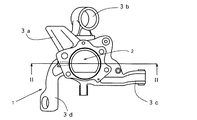
図1は、本発明の一実施の形態に係る自動車用ナックルの正面図である。図2は、図1のII−II断面図である。図3は、全方位型イオン注入装置の概略構成図であり、図4は、その回転テーブルの他の実施態様を示す一部断面図である。
【0028】
本発明の一実施の形態に係る自動車用ナックル1(以下、ナックル1という)は、図1に示すように、例えば従動輪側に用いるもので、図示しないボールベアリングを装着する嵌合孔2がその中央に形成されている。また、ナックル1は、アッパーサスペンションなどの取り付け用の複数のアーム3a〜3fを延設している。これら複数のアーム3a〜3fは、自動車組み付け時にそれぞれ図示しない各種取付ロッドやサスペンションに連結される。本実施の形態において、ナックル1は、製造の容易さなどからアルミニウムを用いているが、金属製であれば鋳鉄やステンレス製であってもよく、特に軽量化に貢献するために、アルミニウム、アルミニウム合金、マグネシウム、マグネシウム合金、チタン、チタン合金などのいわゆる軽金属の中から適宜選択することができる。
【0029】
本発明のナックル1の成形方法としては、特に限定されないが、鍛造、鋳造、粉末冶金、メタルインジェクションモールディング(MIM)などで製造することができる。本実施の形態においては、重力鋳造法によって製造され、まず金属溶湯(アルミニウム溶湯)にカーボンナノファイバー及びフラーレンの少なくとも一方を混入し、金型によって形成されたキャビティ内に金属溶湯(アルミニウム溶湯)を充填し、加圧する。溶湯が固化した後、ナックル1をキャビティから取りだし、所望の切削加工を施して最終製品であるナックル1を得る。
【0030】
ナックル1において、炭素繊維およびフラーレンを合わせて0.01〜50重量%含むことが好ましい。炭素繊維およびフラーレンの割合が50重量%を超えると成形性の点で好ましくなく、0.01重量%未満であると、靭性を十分向上することができない場合がある。なお、上記重量割合は、炭素繊維およびフラーレンをそれぞれ単独で含有する場合は、炭素繊維およびフラーレン単独の重量%である。
【0031】
また、金属例えばアルミニウムに混入させるカーボンナノファイバーは、平均直径が0.7nm〜500nmであって、平均長さが0.01〜1000μmのカーボンナノファイバーを用いることが好ましい。また、カーボンナノファイバーの配合量は、成形時の流動性、得られるナックルの剛性、特に靭性などの観点から、ナックル1の金属例えばアルミニウム中に0.01〜50重量%の範囲で含まれていることが好ましい。このようなカーボンナノファイバーは、炭素六角網面のグラフェンシートが円筒状に閉じた単層構造あるいはこれらの円筒構造が入れ子状に配置された多層構造をしたいわゆるカーボンナノチューブなどである。カーボンナノチューブは、単層構造のみから構成されていても多層構造のみから構成されていても良く、単層構造と多層構造が混在していてもかまわない。また、部分的にカーボンナノチューブの構造を有している炭素材料も使用することができる。なお、カーボンナノチューブという名称の他にグラファイトフィブリルナノチューブといった名称で称されることもある。
【0032】
単層カーボンナノチューブもしくは多層カーボンナノチューブは、アーク放電法、レーザーアブレーション法、気相成長法などによって望ましいサイズに製造される。
【0033】
アーク放電法は、大気圧よりもやや低い圧力のアルゴンや水素雰囲気下で、炭素棒でできた電極材料の間にアーク放電を行うことで、陰極に堆積した多層カーボンナノチューブを得るものである。また、単層カーボンナノチューブは、前記炭素棒中にニッケル/コバルトなどの触媒を混ぜてアーク放電を行い、処理容器の内側面に付着するすすから得られる。
【0034】
レーザーアブレーション法は、希ガス(例えばアルゴン)中で、ターゲットであるニッケル/コバルトなどの触媒を混ぜた炭素表面にYAGレーザーの強いパルスレーザー光を照射することによって炭素表面が溶融・蒸発し、単層カーボンナノチューブを得るものである。
【0035】
気相成長法は、ベンゼンやトルエン等の炭化水素を気相で熱分解し、カーボンナノチューブを合成するもので、流動触媒法やゼオライト担持触媒法などがある。
【0036】
カーボンナノファイバーは、金属例えばアルミニウムに混入する前に、あらかじめ表面処理例えば、イオン注入処理、スパッタエッチング処理、プラズマ処理などを行うことによって、アルミニウムとの接着性やぬれ性を改善することができる。
【0037】
(イオン注入処理)
イオン注入処理(ion implantation)は、イオン源によってイオン化された元素例えば酸素などに加速器によって必要なエネルギーを与え、真空ポンプによって高真空状態に保たれた真空チャンバにあるカーボンナノファイバーの表面内にイオンを打ちこむものである。
【0038】
本発明の一実施の形態のイオン注入処理について、図3に示す全方位型イオン注入装置の概略構成図を用いて説明する。全方位型イオン注入装置50は、真空ポンプ57に接続された例えばステンレス製の真空チャンバー51内にイオン注入処理を施す試料(例えばカーボンナノファイバー52)を置く回転テーブル53が回転自在に配置されている。回転テーブル53は、パルスバイアス電源54に接続され、真空チャンバー51との間は絶縁体55によって絶縁されている。真空チャンバー51は、プロセスガス供給装置58と、高周波電源59に接続されたコイル60と、アーク式蒸発源61と、真空チャンバー51内温度を測定する赤外線放射温度計62と接続されている。
【0039】
イオン注入処理は、真空ポンプ57によって適当な真空状態とされた真空チャンバー51内に、プロセスガス供給装置58からガスが供給され、高周波電源59によってコイル60の周りにプラズマを発生させる。これによってイオン化されたガスが、パルスバイアス電源54の負極に接続されている試料例えばカーボンナノファイバー52に引き込まれ、注入される。また、真空チャンバー51に接続されたアーク式蒸発源61によって、金属イオンを試料例えばカーボンナノファイバー52に注入させることができる。この場合、アーク式蒸発源61内の金属蒸発源は、図示せぬ直流アーク電源に接続され、アーク放電によって蒸発させられる。このとき、回転テーブル53及び試料例えばカーボンナノファイバー52は、スイッチ63によって切りかえられた負の直流バイアス電源56により印加されているので、金属イオンが試料例えばカーボンナノファイバー52に注入される。
【0040】
また、全方位型イオン注入装置50の回転テーブル53を図4に示すような攪拌羽53a及び容器53bを有する構造としてもよい。容器53bは、広口の開口部を上方に有し、容器53b中には試料例えばカーボンナノファイバー52を配置できる。イオン注入処理の間、カーボンナノファイバー52のような粉体の試料は、攪拌羽53aの回転によって攪拌されることで、全体にまんべんなくイオン注入処理を受けることができる。攪拌翼53aの回転速度は、カーボンナノファイバー52の量や、イオン注入処理時間などによって適宜調整することができる。
【0041】
イオン注入処理されたカーボンナノファイバーは、その表面が化学的に改質され、ナックル1の金属例えばアルミニウムに対するぬれ性や接着性などが改善され、ナックル1の剛性、特に破壊靭性の向上が得られる。
【0042】
イオン注入処理に用いられる元素は、例えば、酸素(O)、窒素(N)、塩素(Cl)、クロム(Cr)、炭素(C)、ホウ素(B)、チタン(Ti)、モリブデン(Mo)、リン(P)、アルミニウム(Al)等、ナックル1の金属例えばアルミニウムとの相性によって適宜選択することができる。
【0043】
(スパッタエッチング処理)
ドライエッチング方式のスパッタエッチング処理は、真空ポンプによって高真空状態に保たれた真空チャンバ内にエッチングガス、極低圧不活性ガス雰囲気例えばアルゴン(Ar)中で、交流を印加してグロー放電を行わせ、かつグロー放電によって生じたプラズマ中に露出される電極と接触したカーボンナノファイバーの表面にイオンを衝突させることで、エッチングするものである。
【0044】
スパッタエッチング処理されたカーボンナノファイバーの表面は、物理的にエッチングされることで、微細(ナノサイズ)な凹凸が形成される。このカーボンナノファイバーの表面の凹凸が、ナックル1の金属例えばアルミニウムとの接触面積を増大させることとなり、アルミニウムとカーボンナノファイバーとの接着強度を向上させることができる。アルミニウムにカーボンナノファイバーを混入させ製造したナックル1における剛性、特に破壊靭性の向上が得られる。
【0045】
(プラズマ処理)
プラズマ処理は、プラズマをカーボンナノファイバーに照射することによって表面を改質させるものである。プラズマ処理は、一般的なグロー放電処理やコロナ放電処理などを採用することができる。
【0046】
例えばプラズマは、相対向する放電極と対向電極との間に、パルス生成回路によって生成された高電圧・高頻度のパルス電圧を印加し、両電極間にコロナ放電を惹起して空気中にプラズマを発生させるようにしている。そして、被処理物は、両電極間に静止状態又は移動状態で配置され、その表面にプラズマ処理が施される。
【0047】
プラズマの作り方には、2枚の平行平板電極に数百から数千ボルトの電圧をかけて放電する二極放電タイプ、熱陰極から発した大量の電子が陽極に入るまでに気体分子と衝突しプラズマを作る熱電子放電タイプ、磁場を使って高真空で放電するマグネトロン放電タイプ、高周波電磁誘導によりプラズマを発生させる無電極放電タイプ、磁場のある共振室へマイクロ波を送りこみ電子を共振させるECR(Electron Cyclotron Resonance)放電タイプなどがあり、適宜選択することができる。
【0048】
このようにプラズマ処理されたカーボンナノファイバーの表面は、ナックル1の金属例えばアルミニウムとの接着性やぬれ性が改善し、アルミニウムにカーボンナノファイバーを混入させて製造したナックル1における剛性、特に破壊靭性の向上が得られる。
【0049】
本実施の形態に用いられるフラーレンは、球殻状炭素例えばカーボン60(以下C60とする)、C70、C74、C76、C78、C82、C84、C720、C860などのフラーレン類などが挙げられるが、C60を主成分とすることが好ましい。また、C60を主成分として、C70がC60よりも少量含まれるフラーレンを用いることが好ましい。さらに、C60を主成分として、他のフラーレン類を含んでもよいし、フラーレン以外のフラーレン生成時に同時に生成された他の炭素及び炭素化合物を含んでもよい。フラーレン類の形態は、例えば、サッカーボール状、バッキーボール状などであってもよい。
【0050】
また、フラーレン類は置換基の導入などにより修飾されていてもよい。修飾方法は、特に限定されず、例えば、フラーレン類の反応性に富む炭素5員環部を化学的に修飾できる。置換基の種類は、特に限定されず、例えば、アルキル基、アリール基、アラルキル基、ジオキソラン単位、ハロゲン又は酸素原子などが例示でき、液晶ポリマー、色素類、ポリエチレンオキシドなどの導入により修飾してもよい。フラーレン類の修飾により、選択された金属例えばアルミニウムとの親和性の改善、フラーレン類の分散を可能にする。
【0051】
C60フラーレンは、黒鉛電極を用い、ヘリウム雰囲気でアーク放電し、得られたススをベンゼンで抽出し、得られたC60混合物を、塩基性活性アルミナを担体とし、ヘキサンを展開溶媒として、カラム分離精製することにより調製した。フラーレンを得る方法は、このアーク放電法に限らず、他の手法でもよい。
【0052】
このようにナックル1の金属例えばアルミニウムにフラーレンを混入させて製造したナックル1における剛性、特に破壊靭性の向上が得られる。
【0053】
なお、本発明は、本実施の形態に限定されるものではなく、本発明の要旨の範囲内において種々の形態に変形可能である。
【0054】
例えば、ナックル1を構成するアルミニウムまたはアルミニウム合金に、マグネシウムまたはマグネシウム合金を数パーセント混入させた複合材料とするなど、例えばアルミニウム、マグネシウム、チタンを主成分とする金属に、他の金属を混入させてもよい。
【0055】
また、上記実施の形態では、従動輪側のナックル1について説明したが、駆動輪側のナックルであってもよい。
【図面の簡単な説明】
【図1】本発明の一実施の形態に係る自動車用ナックルの正面図である。
【図2】本発明の一実施の形態に係る自動車用ナックルのII−II断面図である。
【図3】本発明の一実施の形態に用いられる全方位型イオン注入装置の概略説明図である。
【図4】全方位型イオン注入装置の回転テーブルの他の実施態様を示す一部断面図である。
【符号の説明】
1 ナックル
2 嵌合孔
3a〜3f アーム
50 全方位型イオン注入装置
53 回転テーブル
53a 攪拌羽
53b 容器[0001]
TECHNICAL FIELD OF THE INVENTION
The present invention relates to a knuckle for an automobile.
[0002]
[Background Art]
An automobile knuckle is a so-called wheel bearing member, and cast iron is used as a general material. While the weight of automobile parts is required to be reduced, there is a knuckle for automobiles made of aluminum (Patent Document 1).
[0003]
[Patent Document 1]
JP-A-8-324450 (pages 1-4, FIG. 1)
[0004]
[Problems to be solved by the invention]
However, in the conventional lightweight aluminum knuckle, aluminum itself has lower rigidity, particularly toughness, than iron, and therefore requires a rib structure or a buildup for reinforcement. These rib structures and overlays reduce not only the difficulty in designing a knuckle for an automobile but also the effect of reducing the weight of the material by that much.
[0005]
SUMMARY OF THE INVENTION It is an object of the present invention to provide a knuckle for an automobile that can improve rigidity and can be reduced in weight while maintaining rigidity.
[0006]
[Means for Solving the Problems]
In order to solve the above problems, a knuckle for an automobile according to a first aspect of the present invention is formed of a metal containing at least one of carbon fiber and fullerene which is spherical shell carbon.
[0007]
According to the first aspect of the present invention, by forming a metal containing at least one of carbon fiber and fullerene, rigidity, particularly fracture toughness can be improved, and a knuckle for an automobile while maintaining the rigidity can be obtained. The weight can be reduced.
[0008]
Here, in the automobile knuckle according to the first aspect of the present invention,
The carbon fibers may be carbon nanofibers having an average diameter of 0.7 to 500 nm and an average length of 0.01 to 1000 μm.
[0009]
With such a configuration, the stiffness, particularly toughness, of the knuckle for an automobile can be improved.
[0010]
Here, in the automobile knuckle according to the first aspect of the present invention,
The metal can be aluminum or an aluminum alloy.
[0011]
With such a configuration, the rigidity can be improved, and the weight can be reduced while maintaining the rigidity. This can contribute to a reduction in the weight of the body of the automobile.
[0012]
Here, in the automobile knuckle according to the first aspect of the present invention,
The metal can be magnesium or a magnesium alloy.
[0013]
With such a configuration, the rigidity can be improved, and the weight can be reduced while maintaining the rigidity. This can contribute to a reduction in the weight of the body of the automobile.
[0014]
Here, in the automobile knuckle according to the first aspect of the present invention,
The metal can be titanium or a titanium alloy.
[0015]
With such a configuration, the rigidity can be improved, and the weight can be reduced while maintaining the rigidity. This can contribute to a reduction in the weight of the body of the automobile.
[0016]
Here, in the automobile knuckle according to the first aspect of the present invention,
The carbon nanofiber may be subjected to an ion implantation process.
[0017]
With this configuration, the ion-implanted carbon nanofiber is bonded to the metal (aluminum, magnesium, titanium, etc.) constituting the knuckle and the carbon nanofiber at least by changing the chemical composition of its surface. The stiffness and especially the toughness of the knuckle for automobiles can be further improved, and the dispersibility of the carbon nanofiber in the metal can be improved, so that the overall performance can be uniform. .
[0018]
Here, in the automobile knuckle according to the first aspect of the present invention,
The carbon nanofiber may be subjected to a sputter etching process.
[0019]
With such a configuration, the carbon nanofibers subjected to the sputter etching process have fine irregularities on the surface thereof, so that the metal (aluminum, magnesium, titanium, etc.) constituting the knuckle is bonded to the carbon nanofibers. The stiffness and especially the toughness of the knuckle for automobiles can be further improved, and the dispersibility of the carbon nanofiber in the metal can be improved, so that the overall performance can be uniform. .
[0020]
Here, in the automobile knuckle according to the first aspect of the present invention,
The carbon nanofiber can be plasma-treated.
[0021]
With such a configuration, the carbon nanofibers subjected to the plasma treatment are subjected to surface modification such as forming fine irregularities on the surface thereof, and thus the metal (aluminum, magnesium, titanium, etc.) constituting the knuckle for an automobile is formed. ) And carbon nanofiber are improved in adhesiveness and wetting, and the stiffness, especially toughness, of the knuckle for automobiles can be further improved. Performance.
[0022]
Here, in the automobile knuckle according to the first aspect of the present invention,
The fullerene includes carbon 60 and carbon 70,
The carbon 60 may be contained more than the carbon 70.
[0023]
With such a configuration, in the process of synthesizing fullerene, carbon 60 synthesized more than carbon 70 can be effectively used. In particular, since fullerene has high dispersibility in metal, uniform characteristics can be obtained in the entire knuckle for an automobile.
[0024]
Here, in the automobile knuckle according to the first aspect of the present invention,
The metal may contain carbon and a carbon compound obtained in a synthesis process of at least one of the carbon nanofiber and the fullerene.
[0025]
With such a configuration, carbon and carbon compounds, which are impurities synthesized, can be effectively used in the process of synthesizing carbon nanofibers and / or fullerenes.
[0026]
BEST MODE FOR CARRYING OUT THE INVENTION
Hereinafter, embodiments of the present invention will be described in detail with reference to the drawings.
[0027]
FIG. 1 is a front view of a knuckle for a vehicle according to one embodiment of the present invention. FIG. 2 is a sectional view taken along line II-II of FIG. FIG. 3 is a schematic configuration diagram of an omnidirectional ion implantation apparatus, and FIG. 4 is a partial cross-sectional view showing another embodiment of the turntable.
[0028]
A knuckle 1 (hereinafter, referred to as a knuckle 1) for an automobile according to an embodiment of the present invention is used, for example, on a driven wheel side as shown in FIG. 1 and has a
[0029]
The method of forming the
[0030]
The
[0031]
The carbon nanofiber to be mixed with a metal such as aluminum is preferably a carbon nanofiber having an average diameter of 0.7 nm to 500 nm and an average length of 0.01 to 1000 μm. The amount of the carbon nanofibers contained in the metal of the
[0032]
The single-walled carbon nanotube or the multi-walled carbon nanotube is manufactured to a desired size by an arc discharge method, a laser ablation method, a vapor phase growth method, or the like.
[0033]
The arc discharge method is to obtain multi-walled carbon nanotubes deposited on a cathode by performing arc discharge between electrode materials made of carbon rods in an atmosphere of argon or hydrogen at a pressure slightly lower than atmospheric pressure. Further, the single-walled carbon nanotube is obtained by mixing a catalyst such as nickel / cobalt into the carbon rod, performing arc discharge, and soot adhering to the inner surface of the processing container.
[0034]
In the laser ablation method, a carbon surface mixed with a catalyst such as nickel / cobalt as a target is irradiated with a strong pulsed laser beam of a YAG laser in a rare gas (eg, argon) to melt and evaporate the carbon surface. This is to obtain a single-walled carbon nanotube.
[0035]
The vapor phase growth method is a method in which hydrocarbons such as benzene and toluene are thermally decomposed in a gas phase to synthesize carbon nanotubes, and examples thereof include a fluidized catalyst method and a zeolite supported catalyst method.
[0036]
Before the carbon nanofiber is mixed with a metal such as aluminum, a surface treatment such as an ion implantation treatment, a sputter etching treatment, and a plasma treatment can be performed in advance to improve the adhesiveness and wettability with aluminum.
[0037]
(Ion implantation processing)
Ion implantation is a process in which necessary energy is given to an element ionized by an ion source, such as oxygen, by an accelerator, and ions are implanted in the surface of a carbon nanofiber in a vacuum chamber maintained in a high vacuum state by a vacuum pump. It is something to drive.
[0038]
The ion implantation processing according to one embodiment of the present invention will be described with reference to the schematic configuration diagram of the omnidirectional ion implantation apparatus shown in FIG. In the omnidirectional
[0039]
In the ion implantation process, a gas is supplied from a process
[0040]
Further, the rotary table 53 of the
[0041]
The surface of the ion-implanted carbon nanofiber is chemically modified, the wettability and adhesion of the
[0042]
Elements used for the ion implantation treatment include, for example, oxygen (O), nitrogen (N), chlorine (Cl), chromium (Cr), carbon (C), boron (B), titanium (Ti), and molybdenum (Mo). , Phosphorus (P), aluminum (Al), etc., can be appropriately selected depending on the compatibility with the metal of the
[0043]
(Sputter etching treatment)
In the dry etching sputter etching process, glow discharge is performed by applying an alternating current in an etching gas or an ultra-low pressure inert gas atmosphere such as argon (Ar) in a vacuum chamber maintained in a high vacuum state by a vacuum pump. In addition, etching is performed by colliding ions with the surface of the carbon nanofiber in contact with the electrode exposed in the plasma generated by the glow discharge.
[0044]
The surface of the carbon nanofiber that has been subjected to the sputter etching treatment is physically etched to form fine (nano-sized) irregularities. The irregularities on the surface of the carbon nanofibers increase the contact area of the
[0045]
(Plasma treatment)
The plasma treatment modifies the surface by irradiating the carbon nanofibers with plasma. As the plasma processing, general glow discharge processing, corona discharge processing, or the like can be employed.
[0046]
For example, a plasma applies a high-voltage / high-frequency pulse voltage generated by a pulse generation circuit between a discharge electrode and a counter electrode facing each other, causing a corona discharge between the two electrodes and causing a plasma in the air. Is caused to occur. The object to be processed is arranged in a stationary state or a moving state between the two electrodes, and its surface is subjected to plasma processing.
[0047]
The method of plasma generation is a bipolar discharge type in which a voltage of several hundred to several thousand volts is applied to two parallel flat electrodes to discharge them. A large amount of electrons emitted from a hot cathode collide with gas molecules before entering the anode. Thermionic discharge type that generates plasma, magnetron discharge type that discharges in a high vacuum using a magnetic field, electrodeless discharge type that generates plasma by high-frequency electromagnetic induction, ECR that sends microwaves to a resonance chamber with a magnetic field to resonate electrons (Electron Cyclotron Resonance) discharge type and the like can be selected as appropriate.
[0048]
The surface of the carbon nanofiber thus plasma-treated has improved adhesion and wettability with the metal of the
[0049]
The fullerene used in the present embodiment includes spherical shell carbon such as fullerenes such as carbon 60 (hereinafter referred to as C60), C70, C74, C76, C78, C82, C84, C720, and C860. Is preferably a main component. Further, it is preferable to use fullerene containing C60 as a main component and containing C70 in a smaller amount than C60. Further, C60 may be the main component, and may include other fullerenes, or may include other carbon and carbon compounds simultaneously generated when fullerene other than fullerene is generated. The form of the fullerenes may be, for example, a soccer ball shape, a bucky ball shape, or the like.
[0050]
Further, the fullerenes may be modified by introducing a substituent or the like. The modification method is not particularly limited, and for example, a 5-membered carbon ring portion of a fullerene having high reactivity can be chemically modified. The type of the substituent is not particularly limited, and examples thereof include an alkyl group, an aryl group, an aralkyl group, a dioxolane unit, a halogen or an oxygen atom, and the like, and the modification may be performed by introducing a liquid crystal polymer, a dye, polyethylene oxide, or the like. Good. Modification of fullerenes allows for improved affinity with selected metals, such as aluminum, and dispersion of fullerenes.
[0051]
C60 fullerene was subjected to arc discharge in a helium atmosphere using a graphite electrode, the resulting soot was extracted with benzene, and the resulting C60 mixture was purified by column separation using basic activated alumina as a carrier and hexane as a developing solvent. Prepared. The method for obtaining fullerene is not limited to the arc discharge method, but may be another method.
[0052]
As described above, the rigidity, particularly the fracture toughness, of the
[0053]
It should be noted that the present invention is not limited to the present embodiment, and can be modified into various forms within the scope of the present invention.
[0054]
For example, a composite material in which magnesium or a magnesium alloy is mixed with aluminum or an aluminum alloy constituting the
[0055]
Further, in the above-described embodiment, the
[Brief description of the drawings]
FIG. 1 is a front view of a knuckle for an automobile according to an embodiment of the present invention.
FIG. 2 is a cross-sectional view of the knuckle for a vehicle according to the embodiment of the present invention, taken along line II-II.
FIG. 3 is a schematic explanatory view of an omnidirectional ion implantation apparatus used in one embodiment of the present invention.
FIG. 4 is a partial sectional view showing another embodiment of the rotary table of the omnidirectional ion implantation apparatus.
[Explanation of symbols]
Claims (10)
炭素繊維及び球殻状炭素であるフラーレンの少なくとも一方を含有する金属によって形成される、自動車用ナックル。In knuckles for automobiles,
An automobile knuckle formed of a metal containing at least one of carbon fiber and fullerene which is spherical shell carbon.
前記炭素繊維は、平均直径が0.7〜500nmであって平均長さが0.01〜1000μmであるカーボンナノファイバーである、自動車用ナックル。The knuckle for an automobile according to claim 1,
The knuckle for an automobile, wherein the carbon fiber is a carbon nanofiber having an average diameter of 0.7 to 500 nm and an average length of 0.01 to 1000 μm.
前記金属は、アルミニウムまたはアルミニウム合金である、自動車用ナックル。The knuckle for an automobile according to claim 1 or 2,
The knuckle for a vehicle, wherein the metal is aluminum or an aluminum alloy.
前記金属は、マグネシウムまたはマグネシウム合金である、自動車用ナックル。The knuckle for an automobile according to claim 1 or 2,
The knuckle for an automobile, wherein the metal is magnesium or a magnesium alloy.
前記金属は、チタンまたはチタン合金である、自動車用ナックル。The knuckle for an automobile according to claim 1 or 2,
The knuckle for a vehicle, wherein the metal is titanium or a titanium alloy.
前記カーボンナノファイバーは、イオン注入処理されている、自動車用ナックル。In any one of the knuckles for a vehicle according to claim 2,
A knuckle for an automobile, wherein the carbon nanofiber has been subjected to ion implantation.
前記カーボンナノファイバーは、スパッタエッチング処理されている、自動車用ナックル。In any of the knuckles for automobiles according to claim 1,
A knuckle for an automobile, wherein the carbon nanofiber has been subjected to sputter etching.
前記カーボンナノファイバーは、プラズマ処理されている、自動車用ナックル。In any of the knuckles for automobiles according to claim 1,
An automobile knuckle, wherein the carbon nanofiber is plasma-treated.
前記フラーレンは、カーボン60とカーボン70とを含み、
前記カーボン70より前記カーボン60が多く含有されている、自動車用ナックル。In any of the knuckles for automobiles according to claim 1,
The fullerene includes carbon 60 and carbon 70,
A knuckle for an automobile, wherein the knuckle contains more carbon 60 than carbon 70.
前記金属は、前記カーボンナノファイバー及び前記フラーレンの少なくとも一方の合成過程において得られる炭素及び炭素化合物を含有する、自動車用ナックル。In any of the knuckles for automobiles according to claims 1 to 9,
A knuckle for an automobile, wherein the metal contains carbon and a carbon compound obtained in a synthesis process of at least one of the carbon nanofiber and the fullerene.
Priority Applications (1)
| Application Number | Priority Date | Filing Date | Title |
|---|---|---|---|
| JP2003012414A JP2004225084A (en) | 2003-01-21 | 2003-01-21 | Automobile knuckle |
Applications Claiming Priority (1)
| Application Number | Priority Date | Filing Date | Title |
|---|---|---|---|
| JP2003012414A JP2004225084A (en) | 2003-01-21 | 2003-01-21 | Automobile knuckle |
Publications (1)
| Publication Number | Publication Date |
|---|---|
| JP2004225084A true JP2004225084A (en) | 2004-08-12 |
Family
ID=32901031
Family Applications (1)
| Application Number | Title | Priority Date | Filing Date |
|---|---|---|---|
| JP2003012414A Pending JP2004225084A (en) | 2003-01-21 | 2003-01-21 | Automobile knuckle |
Country Status (1)
| Country | Link |
|---|---|
| JP (1) | JP2004225084A (en) |
Cited By (46)
| Publication number | Priority date | Publication date | Assignee | Title |
|---|---|---|---|---|
| JP2005194346A (en) * | 2004-01-05 | 2005-07-21 | Nissin Kogyo Co Ltd | Carbon fiber composite material and its manufacturing method, carbon fiber composite molding and its manufacturing method, carbon fiber composite metallic material and its manufacturing method, and carbon fiber composite metallic molding and its manufacturing method |
| US7892653B2 (en) | 2005-09-07 | 2011-02-22 | E & F Corporation | Titanium alloy composite material, titanium clad material using the titanium alloy composite material, and method of producing the titanium clad material |
| US8297364B2 (en) | 2009-12-08 | 2012-10-30 | Baker Hughes Incorporated | Telescopic unit with dissolvable barrier |
| US8327931B2 (en) | 2009-12-08 | 2012-12-11 | Baker Hughes Incorporated | Multi-component disappearing tripping ball and method for making the same |
| US8403037B2 (en) | 2009-12-08 | 2013-03-26 | Baker Hughes Incorporated | Dissolvable tool and method |
| US8424610B2 (en) | 2010-03-05 | 2013-04-23 | Baker Hughes Incorporated | Flow control arrangement and method |
| US8425651B2 (en) | 2010-07-30 | 2013-04-23 | Baker Hughes Incorporated | Nanomatrix metal composite |
| US8528633B2 (en) | 2009-12-08 | 2013-09-10 | Baker Hughes Incorporated | Dissolvable tool and method |
| US8573295B2 (en) | 2010-11-16 | 2013-11-05 | Baker Hughes Incorporated | Plug and method of unplugging a seat |
| KR101345031B1 (en) * | 2012-02-20 | 2013-12-26 | 명화공업주식회사 | Manufacturing method of magnesium knuckle using gravity casting and pressure moulding and the magnesium knuckle thereof |
| US8631876B2 (en) | 2011-04-28 | 2014-01-21 | Baker Hughes Incorporated | Method of making and using a functionally gradient composite tool |
| US8776884B2 (en) | 2010-08-09 | 2014-07-15 | Baker Hughes Incorporated | Formation treatment system and method |
| US9068428B2 (en) | 2012-02-13 | 2015-06-30 | Baker Hughes Incorporated | Selectively corrodible downhole article and method of use |
| US9080098B2 (en) | 2011-04-28 | 2015-07-14 | Baker Hughes Incorporated | Functionally gradient composite article |
| US9079246B2 (en) | 2009-12-08 | 2015-07-14 | Baker Hughes Incorporated | Method of making a nanomatrix powder metal compact |
| US9090955B2 (en) | 2010-10-27 | 2015-07-28 | Baker Hughes Incorporated | Nanomatrix powder metal composite |
| US9090956B2 (en) | 2011-08-30 | 2015-07-28 | Baker Hughes Incorporated | Aluminum alloy powder metal compact |
| US9101978B2 (en) | 2002-12-08 | 2015-08-11 | Baker Hughes Incorporated | Nanomatrix powder metal compact |
| US9109269B2 (en) | 2011-08-30 | 2015-08-18 | Baker Hughes Incorporated | Magnesium alloy powder metal compact |
| US9109429B2 (en) | 2002-12-08 | 2015-08-18 | Baker Hughes Incorporated | Engineered powder compact composite material |
| US9127515B2 (en) | 2010-10-27 | 2015-09-08 | Baker Hughes Incorporated | Nanomatrix carbon composite |
| US9133695B2 (en) | 2011-09-03 | 2015-09-15 | Baker Hughes Incorporated | Degradable shaped charge and perforating gun system |
| US9187990B2 (en) | 2011-09-03 | 2015-11-17 | Baker Hughes Incorporated | Method of using a degradable shaped charge and perforating gun system |
| US9227243B2 (en) | 2009-12-08 | 2016-01-05 | Baker Hughes Incorporated | Method of making a powder metal compact |
| US9243475B2 (en) | 2009-12-08 | 2016-01-26 | Baker Hughes Incorporated | Extruded powder metal compact |
| US9284812B2 (en) | 2011-11-21 | 2016-03-15 | Baker Hughes Incorporated | System for increasing swelling efficiency |
| US9347119B2 (en) | 2011-09-03 | 2016-05-24 | Baker Hughes Incorporated | Degradable high shock impedance material |
| US9605508B2 (en) | 2012-05-08 | 2017-03-28 | Baker Hughes Incorporated | Disintegrable and conformable metallic seal, and method of making the same |
| US9643144B2 (en) | 2011-09-02 | 2017-05-09 | Baker Hughes Incorporated | Method to generate and disperse nanostructures in a composite material |
| US9682425B2 (en) | 2009-12-08 | 2017-06-20 | Baker Hughes Incorporated | Coated metallic powder and method of making the same |
| US9707739B2 (en) | 2011-07-22 | 2017-07-18 | Baker Hughes Incorporated | Intermetallic metallic composite, method of manufacture thereof and articles comprising the same |
| US9816339B2 (en) | 2013-09-03 | 2017-11-14 | Baker Hughes, A Ge Company, Llc | Plug reception assembly and method of reducing restriction in a borehole |
| US9833838B2 (en) | 2011-07-29 | 2017-12-05 | Baker Hughes, A Ge Company, Llc | Method of controlling the corrosion rate of alloy particles, alloy particle with controlled corrosion rate, and articles comprising the particle |
| US9856547B2 (en) | 2011-08-30 | 2018-01-02 | Bakers Hughes, A Ge Company, Llc | Nanostructured powder metal compact |
| US9910026B2 (en) | 2015-01-21 | 2018-03-06 | Baker Hughes, A Ge Company, Llc | High temperature tracers for downhole detection of produced water |
| US9926766B2 (en) | 2012-01-25 | 2018-03-27 | Baker Hughes, A Ge Company, Llc | Seat for a tubular treating system |
| US9926763B2 (en) | 2011-06-17 | 2018-03-27 | Baker Hughes, A Ge Company, Llc | Corrodible downhole article and method of removing the article from downhole environment |
| US10016810B2 (en) | 2015-12-14 | 2018-07-10 | Baker Hughes, A Ge Company, Llc | Methods of manufacturing degradable tools using a galvanic carrier and tools manufactured thereof |
| US10092953B2 (en) | 2011-07-29 | 2018-10-09 | Baker Hughes, A Ge Company, Llc | Method of controlling the corrosion rate of alloy particles, alloy particle with controlled corrosion rate, and articles comprising the particle |
| US10221637B2 (en) | 2015-08-11 | 2019-03-05 | Baker Hughes, A Ge Company, Llc | Methods of manufacturing dissolvable tools via liquid-solid state molding |
| US10240419B2 (en) | 2009-12-08 | 2019-03-26 | Baker Hughes, A Ge Company, Llc | Downhole flow inhibition tool and method of unplugging a seat |
| US10301909B2 (en) | 2011-08-17 | 2019-05-28 | Baker Hughes, A Ge Company, Llc | Selectively degradable passage restriction |
| US10378303B2 (en) | 2015-03-05 | 2019-08-13 | Baker Hughes, A Ge Company, Llc | Downhole tool and method of forming the same |
| US11167343B2 (en) | 2014-02-21 | 2021-11-09 | Terves, Llc | Galvanically-active in situ formed particles for controlled rate dissolving tools |
| US11365164B2 (en) | 2014-02-21 | 2022-06-21 | Terves, Llc | Fluid activated disintegrating metal system |
| US11649526B2 (en) | 2017-07-27 | 2023-05-16 | Terves, Llc | Degradable metal matrix composite |
-
2003
- 2003-01-21 JP JP2003012414A patent/JP2004225084A/en active Pending
Cited By (59)
| Publication number | Priority date | Publication date | Assignee | Title |
|---|---|---|---|---|
| US9101978B2 (en) | 2002-12-08 | 2015-08-11 | Baker Hughes Incorporated | Nanomatrix powder metal compact |
| US9109429B2 (en) | 2002-12-08 | 2015-08-18 | Baker Hughes Incorporated | Engineered powder compact composite material |
| JP2005194346A (en) * | 2004-01-05 | 2005-07-21 | Nissin Kogyo Co Ltd | Carbon fiber composite material and its manufacturing method, carbon fiber composite molding and its manufacturing method, carbon fiber composite metallic material and its manufacturing method, and carbon fiber composite metallic molding and its manufacturing method |
| US7892653B2 (en) | 2005-09-07 | 2011-02-22 | E & F Corporation | Titanium alloy composite material, titanium clad material using the titanium alloy composite material, and method of producing the titanium clad material |
| US8528633B2 (en) | 2009-12-08 | 2013-09-10 | Baker Hughes Incorporated | Dissolvable tool and method |
| US8297364B2 (en) | 2009-12-08 | 2012-10-30 | Baker Hughes Incorporated | Telescopic unit with dissolvable barrier |
| US9682425B2 (en) | 2009-12-08 | 2017-06-20 | Baker Hughes Incorporated | Coated metallic powder and method of making the same |
| US9243475B2 (en) | 2009-12-08 | 2016-01-26 | Baker Hughes Incorporated | Extruded powder metal compact |
| US9227243B2 (en) | 2009-12-08 | 2016-01-05 | Baker Hughes Incorporated | Method of making a powder metal compact |
| US8327931B2 (en) | 2009-12-08 | 2012-12-11 | Baker Hughes Incorporated | Multi-component disappearing tripping ball and method for making the same |
| US10240419B2 (en) | 2009-12-08 | 2019-03-26 | Baker Hughes, A Ge Company, Llc | Downhole flow inhibition tool and method of unplugging a seat |
| US8714268B2 (en) | 2009-12-08 | 2014-05-06 | Baker Hughes Incorporated | Method of making and using multi-component disappearing tripping ball |
| US8403037B2 (en) | 2009-12-08 | 2013-03-26 | Baker Hughes Incorporated | Dissolvable tool and method |
| US9022107B2 (en) | 2009-12-08 | 2015-05-05 | Baker Hughes Incorporated | Dissolvable tool |
| US10669797B2 (en) | 2009-12-08 | 2020-06-02 | Baker Hughes, A Ge Company, Llc | Tool configured to dissolve in a selected subsurface environment |
| US9079246B2 (en) | 2009-12-08 | 2015-07-14 | Baker Hughes Incorporated | Method of making a nanomatrix powder metal compact |
| US8424610B2 (en) | 2010-03-05 | 2013-04-23 | Baker Hughes Incorporated | Flow control arrangement and method |
| US8425651B2 (en) | 2010-07-30 | 2013-04-23 | Baker Hughes Incorporated | Nanomatrix metal composite |
| US8776884B2 (en) | 2010-08-09 | 2014-07-15 | Baker Hughes Incorporated | Formation treatment system and method |
| US9127515B2 (en) | 2010-10-27 | 2015-09-08 | Baker Hughes Incorporated | Nanomatrix carbon composite |
| US9090955B2 (en) | 2010-10-27 | 2015-07-28 | Baker Hughes Incorporated | Nanomatrix powder metal composite |
| US8573295B2 (en) | 2010-11-16 | 2013-11-05 | Baker Hughes Incorporated | Plug and method of unplugging a seat |
| US8631876B2 (en) | 2011-04-28 | 2014-01-21 | Baker Hughes Incorporated | Method of making and using a functionally gradient composite tool |
| US9080098B2 (en) | 2011-04-28 | 2015-07-14 | Baker Hughes Incorporated | Functionally gradient composite article |
| US10335858B2 (en) | 2011-04-28 | 2019-07-02 | Baker Hughes, A Ge Company, Llc | Method of making and using a functionally gradient composite tool |
| US9631138B2 (en) | 2011-04-28 | 2017-04-25 | Baker Hughes Incorporated | Functionally gradient composite article |
| US9926763B2 (en) | 2011-06-17 | 2018-03-27 | Baker Hughes, A Ge Company, Llc | Corrodible downhole article and method of removing the article from downhole environment |
| US10697266B2 (en) | 2011-07-22 | 2020-06-30 | Baker Hughes, A Ge Company, Llc | Intermetallic metallic composite, method of manufacture thereof and articles comprising the same |
| US9707739B2 (en) | 2011-07-22 | 2017-07-18 | Baker Hughes Incorporated | Intermetallic metallic composite, method of manufacture thereof and articles comprising the same |
| US10092953B2 (en) | 2011-07-29 | 2018-10-09 | Baker Hughes, A Ge Company, Llc | Method of controlling the corrosion rate of alloy particles, alloy particle with controlled corrosion rate, and articles comprising the particle |
| US9833838B2 (en) | 2011-07-29 | 2017-12-05 | Baker Hughes, A Ge Company, Llc | Method of controlling the corrosion rate of alloy particles, alloy particle with controlled corrosion rate, and articles comprising the particle |
| US10301909B2 (en) | 2011-08-17 | 2019-05-28 | Baker Hughes, A Ge Company, Llc | Selectively degradable passage restriction |
| US10737321B2 (en) | 2011-08-30 | 2020-08-11 | Baker Hughes, A Ge Company, Llc | Magnesium alloy powder metal compact |
| US9090956B2 (en) | 2011-08-30 | 2015-07-28 | Baker Hughes Incorporated | Aluminum alloy powder metal compact |
| US9802250B2 (en) | 2011-08-30 | 2017-10-31 | Baker Hughes | Magnesium alloy powder metal compact |
| US11090719B2 (en) | 2011-08-30 | 2021-08-17 | Baker Hughes, A Ge Company, Llc | Aluminum alloy powder metal compact |
| US9856547B2 (en) | 2011-08-30 | 2018-01-02 | Bakers Hughes, A Ge Company, Llc | Nanostructured powder metal compact |
| US9925589B2 (en) | 2011-08-30 | 2018-03-27 | Baker Hughes, A Ge Company, Llc | Aluminum alloy powder metal compact |
| US9109269B2 (en) | 2011-08-30 | 2015-08-18 | Baker Hughes Incorporated | Magnesium alloy powder metal compact |
| US9643144B2 (en) | 2011-09-02 | 2017-05-09 | Baker Hughes Incorporated | Method to generate and disperse nanostructures in a composite material |
| US9347119B2 (en) | 2011-09-03 | 2016-05-24 | Baker Hughes Incorporated | Degradable high shock impedance material |
| US9187990B2 (en) | 2011-09-03 | 2015-11-17 | Baker Hughes Incorporated | Method of using a degradable shaped charge and perforating gun system |
| US9133695B2 (en) | 2011-09-03 | 2015-09-15 | Baker Hughes Incorporated | Degradable shaped charge and perforating gun system |
| US9284812B2 (en) | 2011-11-21 | 2016-03-15 | Baker Hughes Incorporated | System for increasing swelling efficiency |
| US9926766B2 (en) | 2012-01-25 | 2018-03-27 | Baker Hughes, A Ge Company, Llc | Seat for a tubular treating system |
| US9068428B2 (en) | 2012-02-13 | 2015-06-30 | Baker Hughes Incorporated | Selectively corrodible downhole article and method of use |
| KR101345031B1 (en) * | 2012-02-20 | 2013-12-26 | 명화공업주식회사 | Manufacturing method of magnesium knuckle using gravity casting and pressure moulding and the magnesium knuckle thereof |
| US10612659B2 (en) | 2012-05-08 | 2020-04-07 | Baker Hughes Oilfield Operations, Llc | Disintegrable and conformable metallic seal, and method of making the same |
| US9605508B2 (en) | 2012-05-08 | 2017-03-28 | Baker Hughes Incorporated | Disintegrable and conformable metallic seal, and method of making the same |
| US9816339B2 (en) | 2013-09-03 | 2017-11-14 | Baker Hughes, A Ge Company, Llc | Plug reception assembly and method of reducing restriction in a borehole |
| US11167343B2 (en) | 2014-02-21 | 2021-11-09 | Terves, Llc | Galvanically-active in situ formed particles for controlled rate dissolving tools |
| US11365164B2 (en) | 2014-02-21 | 2022-06-21 | Terves, Llc | Fluid activated disintegrating metal system |
| US11613952B2 (en) | 2014-02-21 | 2023-03-28 | Terves, Llc | Fluid activated disintegrating metal system |
| US9910026B2 (en) | 2015-01-21 | 2018-03-06 | Baker Hughes, A Ge Company, Llc | High temperature tracers for downhole detection of produced water |
| US10378303B2 (en) | 2015-03-05 | 2019-08-13 | Baker Hughes, A Ge Company, Llc | Downhole tool and method of forming the same |
| US10221637B2 (en) | 2015-08-11 | 2019-03-05 | Baker Hughes, A Ge Company, Llc | Methods of manufacturing dissolvable tools via liquid-solid state molding |
| US10016810B2 (en) | 2015-12-14 | 2018-07-10 | Baker Hughes, A Ge Company, Llc | Methods of manufacturing degradable tools using a galvanic carrier and tools manufactured thereof |
| US11649526B2 (en) | 2017-07-27 | 2023-05-16 | Terves, Llc | Degradable metal matrix composite |
| US11898223B2 (en) | 2017-07-27 | 2024-02-13 | Terves, Llc | Degradable metal matrix composite |
Similar Documents
| Publication | Publication Date | Title |
|---|---|---|
| JP2004225084A (en) | Automobile knuckle | |
| JP2004225765A (en) | Disc rotor for disc brake for vehicle | |
| US7056479B2 (en) | Process for preparing carbon nanotubes | |
| JP3544237B2 (en) | Production method of giant fullerene | |
| JP2001064004A (en) | Single layer carbon nano-horn structure and its production | |
| JP2005243646A (en) | Composition for forming electron emission source of electron emission element, and electron emission source using same | |
| JP3910150B2 (en) | Subframe for vehicle | |
| Devi et al. | Carbon-based nanomaterials: carbon nanotube, fullerene, and carbon dots | |
| Wang et al. | Low temperature solvothermal synthesis of multiwall carbon nanotubes | |
| JP3946156B2 (en) | Suspension arm | |
| JP2004308837A (en) | Seal member | |
| JP2004225764A (en) | Caliper body for disc brake | |
| Takikawa et al. | Carbon nanotubes in cathodic vacuum arc discharge | |
| JP2004285400A (en) | Mounting member for vehicle | |
| JP4177210B2 (en) | Method for producing carbon fiber composite metal material | |
| JP3885719B2 (en) | Carbon nanotube manufacturing method and manufacturing apparatus in which part or all of tip end of graphene sheet cylinder is torn | |
| JP2004308777A (en) | Disk rotor of disk brake for vehicle | |
| JP2007077482A (en) | Porous material and its production method, and composite metallic material and its production method | |
| JP2004232786A (en) | Piston seal and disk brake | |
| JPH1192124A (en) | Multinuclear fullerene and multinuclear fullerene structural body | |
| JP2005171358A (en) | Porous composite metallic material and method for manufacturing the same | |
| JP2004308836A (en) | Seal member | |
| JP4177202B2 (en) | Method for producing carbon fiber composite metal material | |
| Raza et al. | Study the electron field emission properties of silver nanoparticles decorated carbon nanotubes-based cold-cathode field emitters via post-plasma treatment | |
| JP2005263523A (en) | Meso-size fine particles and method for manufacturing the same |
Legal Events
| Date | Code | Title | Description |
|---|---|---|---|
| A621 | Written request for application examination |
Free format text: JAPANESE INTERMEDIATE CODE: A621 Effective date: 20040601 |
|
| RD04 | Notification of resignation of power of attorney |
Free format text: JAPANESE INTERMEDIATE CODE: A7424 Effective date: 20051213 |
|
| A131 | Notification of reasons for refusal |
Free format text: JAPANESE INTERMEDIATE CODE: A131 Effective date: 20060201 |
|
| A521 | Written amendment |
Free format text: JAPANESE INTERMEDIATE CODE: A523 Effective date: 20060324 |
|
| A02 | Decision of refusal |
Free format text: JAPANESE INTERMEDIATE CODE: A02 Effective date: 20070404 |