JP2004222013A - Internet protocol telephony sistem - Google Patents
Internet protocol telephony sistem Download PDFInfo
- Publication number
- JP2004222013A JP2004222013A JP2003007746A JP2003007746A JP2004222013A JP 2004222013 A JP2004222013 A JP 2004222013A JP 2003007746 A JP2003007746 A JP 2003007746A JP 2003007746 A JP2003007746 A JP 2003007746A JP 2004222013 A JP2004222013 A JP 2004222013A
- Authority
- JP
- Japan
- Prior art keywords
- network
- telephone
- internet protocol
- existing telephone
- terminal
- Prior art date
- Legal status (The legal status is an assumption and is not a legal conclusion. Google has not performed a legal analysis and makes no representation as to the accuracy of the status listed.)
- Pending
Links
Images


Landscapes
- Telephonic Communication Services (AREA)
- Data Exchanges In Wide-Area Networks (AREA)
Abstract
Description
【0001】
【発明の属する技術分野】
本発明は、インターネットやイントラネットなどのIP(インターネットプロトコルの略称)ネットワークに音声を通すためのVoIP(Voice over IP:インターネットプロトコルで音声を通すことの略称)制御端末を介して、発信側の既存電話端末と受信側の既存電話網を直接又はIP網(デジタル専用線、フレームリレー、インターネット)を介して接続するIP電話システムに関する。
【0002】
【従来の技術】
IPネットワークを介したIP加入電話システムは、ネットワークの網域を効率的に使用することにより通信費の抑制が可能となる。そのため、このシステムを使うIP加入電話サービスは、網内では距離に応じて課金されることのないIP網を介しているので、従来の電話交換網の距離に応じて課金される電話サービスと比較し、低コスト、従来にはない付加サービスの提供が可能であり、今後急速な発展が見込まれている。
【0003】
図4は従来の電話交換網とインターネットプロトコル網を結合した通信網接続装置(例えば、特許文献1を参照)を示す図である。
【0004】
図4で、送信側の電話端末74が着信側の電話端末79にダイアルすると、交換機70はダイアル番号を分析し、チャイルド音声ゲートウエイ64への方路を決定し、チャイルド音声ゲートウエイ64に起動をかけ、ダイアル数字を送出する。チャイルド音声ゲートウエイ64はダイアル数字を受信すると、申告先表に存在するペアレント音声ゲートウエイ60に対して宛先問い合わせメッセージを送信する。ペアレント音声ゲートウエイ60は方路選択表を参照して、宛先数字に相当するトランスポートアドレスを探す。しかし、方路選択表に存在しないとき、ペアレント音声ゲートウエイ60は、宛先問い合わせヘッダのみからなる、宛先問い合わせ失敗メッセージを、宛先問い合わせ失敗メッセージの送信元であるチャイルド音声ゲートウエイ64に送信する。チャイルド音声ゲートウエイ64は宛先問い合わせ失敗メッセージを受信すると、電話交換網10に対してあらためて呼設定を開始する。
【0005】
このIP電話のIP網は、IPアドレスを用いるためにH.323に基づくTCP/IPプロトコルでサポートされている。一方、公衆電話回線GSTNと接続するVoIP端末(チャイルド音声ゲートウエイ64およびペアレント音声ゲートウエイ60)は、GSTN側の呼接続やルーテイング(経路制御)のためのアウトバンド・シグナリングであるSS7とつながなければならないので、完全にアウトバンド・シグナリング・プロトコルを変換しなければならない。しかし、H.323でサポートされているプロトコルは複雑なため、装置の開発が容易ではなく、新たなアプリケーションの開発も容易ではなかった。
【0006】
このアプリケーション開発を容易にするプロトコルとしてSIP(セッション開始プロトコル)がある。
【0007】
このSIPプロトコルは、IETF(Internet Engineering Task Force)の機関で、RFC3261と規定されているプロトコルである。
【0008】
以下、このSIPプロトコルの特性について説明する。
【0009】
電話サービスを実現するためには、通話に必要な動作パラメータが、音声の伝送に先立ってIP電話機に設定される必要がある。必要な動作パラメータとは、(a)音声信号の符号化方法、(b)送信に用いるトランスポート・アドレス(IPアドレスとポート番号)、(c)必要なネットワーク帯域、(d)通話開始、受付の許可、(e)着信相手の居場所などの情報である。
【0010】
これらの情報を、IP電話機間(インターネット電話機間)、およびIP電話機とネットワーク中のサービス提供サーバとの間でやりとりする仕組み(シグナリング)として、SIPが使われる。
【0011】
ただし、SIPの標準の中に、これらすべてのことが規定されているわけではないので、既存のプロトコル、および電子メール型のアドレス表現やHTTP(ハイパーテキスト転送プロトコル)のコードが利用される。
【0012】
SIPは、セッションの開始や終結を行うが、セッションの内容については関知しない。すなわち、SIPは、セッション情報を規定するSDP(セッション記述プロトコル)を用いる仕組みをもっているので、プロトコルの内部にはセッションに関する情報を含まない。これによって、サーバ機能の実装や、サービスを提供するクライアント数を増やすことが容易になる。言い換えれば、セッション情報をもたず、必要に応じてSDPを利用することによって、それぞれのクラィアントの処理に必要なサーバのメモリ量が削減されるので、より多くのクライアントにサービスを提供することができる。
【0013】
SIPに基づく端末のプロトコル構成において、音声やビデオ信号のRTP(リアルタイム伝送プロトコル)パケットは、それぞれUDP(ユーザー・データグラム・プロトコル)/IPによって伝送される。TCPのサポートはオプションである。H.323端末のプロトコルがTCPのサポートが必須であるのと大きく異なる。
【0014】
SlPの通信手順、特に、端末同士の直接通信手順を説明する。
▲1▼まず、発呼側が受話器を持ち上げて、電話番号をダイヤルする。すると、着呼側へ向かって「INVITE」リクエスト(セッション参加要求)が送られる。
▲2▼着呼側に「INVITE」リクエストが届くと、着呼側から発呼側へ向かって、「100Trying」レスポンスが送られる。
▲3▼次いで、着呼側から発呼側に向かって「180Ringing」レスポンスが送られる。そして、着呼側で受話器を取り上げたとき、「2000K」レスポンスが送られる。
▲4▼発呼側からACK(確認応答)が送られることによって、通信のためのポートが開かれて通話ができるようになる。
▲5▼通話を終了するときは、「BYE」メッセージを送る。「BYE」メッセージは、発呼側・着呼側のいずれからでも出すことができる。
「INVITE」リクエストは、セッションヘの参加要求であり、▲1▼着呼側のアドレス、▲2▼発呼側のアドレス、▲3▼通話に使うメディアの定義が含まれている。
【0015】
発呼側、着呼側のアドレスには、電話番号の代わりに電子メール・アドレス型の宛先指示子を用いる。また、100Tryingや180Ringingなどの先頭の3桁は、HTTPで使う3桁のレスポンス・コードの体系に準拠したものを用いる。
【0016】
SIPサーバを利用して通信するときは、ユーザー端末は自分の所在地をREGISTER(登録)リクエストでSIPサーバに登録する。また、ユーザ端末は、登録情報を変更することで、移動先へメッセージの宛先を変更(リダイレクト)する。このSIPサーバを、プロキシー・サーバやリダイレクト・サーバとすることができる。
【0017】
(SIPのメッセージ・フォーマット)
SIPでは、通話の発呼側や着呼側のアドレスを指定するのにURL(Uniform Resource Locator)を用いており、SIP−URLと言う。URLは、インターネットに分散しているリソース(コンピュータ資源)のアドレスを指定し、アクセスするための書式となっている。SIPのURLは、WWWのページのアドレスを指定するURLと同じ規定に従っている。
【0018】
SIP−URLを示すURLは、「sip:」で始まる。その次のフィールドは、ユーザーの識別子である。識別子としては、ユーザー名だけでなく、電話番号を用いることもできる。@の後には、SIPサービスを提供する端末やサーバのホスト名として、ドメイン名あるいはIPアドレスを使うことができる。
【0019】
(SIPのメッセージ書式)
SIPのメッセージは、リクエスト(要求)とレスポンス(応答)に分けられる。リクエストは、電話(IP電話)をかける側のユーザー・エージェント・クライアント(UAC)から、SIPサーバヘ向けて送り出されるメッセージである。これに対してレスポンスは、ユーザー・エージェント・サーバ(UAS)やSIPサーバから、UACへ返される応答メッセージである。
【0020】
(リクエスト)
リクエストのスタート・ラインには、INVITEやACKなどが含まれ、必要に応じてSIP−URLも含まれる。このSIP−URLは、知り得た限りのホスト名までフルに含んだアドレス指定になる。一方、メッセージ・ヘッダには、発呼側のユーザ情報、着呼側のユーザー情報や呼に固有な番号が含まれている。メッセージ・ボディには、SDP(セッション記述プロトコル)に基づいたセッション情報が収納される。セッション情報としては、例えばサポートしている音声コーデックの種類や通話に用いるビット・レートが含まれている。
【0021】
SIPのメッセージ・ヘッダは電子メール・ヘッダと同じルールに従って構成されている。メッセージの「〈〉」の中はメール・アドレスに相当する。
【0022】
(レスポンス)
レスポンスのスタートラインには、3桁の状態コードとその簡単な説明が入る。メッセージ・ヘッダおよびメッセージ・ボデイに関してはリクエストの場合と同じである。
【0023】
(SIPの特徴)
SIPは、テキスト表現のプロトコルで軽く、実装も容易といわれている。一般にSIPは、既存のインターネット技術を応用しているので、WWWとの相性も良い。また、SIPは、SIPサーバを状態の記憶をゼロにできる、即ち、通信状態が移り変わっていく経緯をサーバが記憶しておかなくてもよくなり、例えばH.245の状態遷移型のプロトコルと比べて、拡張性に優れている。
【0024】
PSTN(一般の公衆電話回線)との接続についてみると、VoIP端末は、PSTN側の呼接続、ルーテイング(経路制御)のためのアウトバンド・シグナリングであるSS7とつながる必要がある。アウトバンド・シグナリングとは、呼制御用の信号と、音声通話信号を分けてやりとりする方式である。SIPは、SS7のISUP(音声通話回線をつなぐための情報を送るプロトコル)との親和性を考慮して設計されている。
【0025】
また、プロトコルの表現では、SIPの場合テキスト表現をとり、キャラクタ変換した結果をメッセージそのものとして読むことができる。このため、デバッグやエラー発生時の保守がし易くなり、実装が容易になる。
【0026】
(現状)
現在、IP電話のプロトコルとしてSIPを用いたシステムは見当たらない。本発明はこのこの点にも着目した発明である。
【0027】
【特許文献1】特開2001−298491号公報
【0028】
【発明が解決しようとする課題】
従来の電話サービスと同等の利便性を確保するために、接続できない番号やサービスについては従来の電話網を使って発信し、IP電話として提供可能な番号やサービスに対してはIP網に対して発信するというしくみが必要となる。
【0029】
その際、IP網を使って発信した場合と、既存電話網を使って発信した場合では通話料金が異なることから、ユーザに対して呼毎にどちらを使って発信しているのかを明確に通知することが、ユーザ側の一つの二一ズと考えられる。即ち、低コストのIP電話と考えて長電話したら、実は既存の電話網経由で通話していたため、従来の距離に応じて課金される電話料金を請求されるといった問題を解消する必要が認識されていた。
【0030】
また、IP電話における公衆電話網をサポートするためにより都合の良いプロトコルの採用が必要とされている。
【0031】
そこで、本発明の目的は、前記問題点に鑑み、インターネットプロトコル網が接続可能な番号や提供可能なサービスであるか否かを判断し、インターネットプロトコル網を使って発信できない場合、接続不能信号を戻すインターネットプロトコル電話システムを提供することにある。
【0032】
また、本発明の他の目的は、インターネットプロトコル網が接続可能な番号や提供可能なサービスであるか否かを判断し、インターネットプロトコル網を使って発信した場合と、公衆交換電話網からなる既存電話網を使って発信した場合とを、ユーザに対して明確に通知するインターネットプロトコル電話システムを提供することにある。
【0033】
また、本発明の他の目的は、最適なプロトコルを採用し、インターネットプロトコル網で接続できない番号と判明したとき公衆交換電話網からなる既存電話網を使って接続することを可能とするインターネットプロトコル電話システムを提供することにある。
【0034】
【課題を解決するための手段】
本発明は、前記各目的を達成するために以下の解決手段を採用する。
(1)インターネットプロトコル電話システムにおいて、既存電話端末がVoIP制御端末を介した後、直接およびインターネットプロトコル網を介して既存電話網に接続されるインターネットプロトコル電話システムであって、前記VoIP制御端末に対して、SIPプロトコルによりサポートされているインターネットプロトコル網として提供可能な番号並びにサービスおよび提供不可能な番号を前記インターネットプロトコル網が通知することを特徴とする。
(2)インターネットプロトコル電話システムにおいて、既存電話端末がVoIP制御端末を介した後、ADSL網、ISP、およびインターネットプロトコル網の順に介して既存電話網に接続されると共に、前記VoIP制御端末を介した後直接前記既存電話網に接続されるインターネットプロトコル電話システムであって、前記VoIP制御端末に対して、前記インターネットプロトコル網として提供可能な番号並びにサービスおよび提供不可能な番号を前記インターネットプロトコル網が通知することを特徴とする。
(3)前記(1)又は(2)記載のインターネットプロトコル電話システムにおいて、前記既存電話端末が前記インターネットプロトコル網を介して前記既存電話網に発信しているとき、前記インターネットプロトコル網が発信側の前記既存電話端末を介してその発信状態をユーザに通知することを特徴とする。
【0035】
【発明の実施の形態】
以下、本発明の実施の形態を図に基づいて詳細に説明する。
【0036】
(第1実施例)
図1は本発明のインターネット電話システムの第1実施例を示す図である。主な構成要素を説明する。
【0037】
(VoIP制御端末)
本発明の制御動作を行うVoIP制御端末3は、既存電話端末2とIP網5または既存電話網6へ接続され、従ってIP網5および既存電話網6への接続インタフェースを有し、既存電話端末2の呼に応じてIP網5または既存電話網6のいずれかに発信することを可能とする装置である。ただしVoIP制御端末3自身が既存電話端末2の電話機機能を持つことも可能である。
【0038】
(IP電話制御装置)
IP網5側にあって、VoIP制御端末3からの接続要求を処理し、相手先既存電話端末7に対して接続を行う。またIP網5経由で接続できない番号やサービスヘの接続要求を受信した場合には、VoIP制御端末3に対して既存電話網6を使って発信するよう指示する機能を有する。
【0039】
IP網5として接続可能な(電話)番号や提供可能なサービスであるか否かを判断する方式としては、IP網5側で行う方式(方式1)と既存電話端末2側で行う方式(方式2)の2つが考えられる。これら方式の、接続可能な番号や提供可能なサービスは将来変わり得るため、将来の変更に柔軟に対応できる方式が望ましい。即ち、数干、数万の既存電話端末2個々の設定を変更する必要のある方式2よりも、1ないし数台のIP網5側のIP電話制御装置4の変更により対応可能な方式1のほうが柔軟性の高い方式といえる。
【0040】
そのため、本発明は、前記方式1に基づいて、IP網5が加入電話端末に対してIP網5として接続可能な番号や提供可能なサービスおよび接続不可能な番号を通知する方式をとることを特徴とする。
【0041】
図1のシステム1では、各家庭等の送信側の既存電話端末2はVoIP制御端末3を介して2つの異なるルートで受信側の既存電話端末7に接続可能に構成されている。前記ルートの一方は、VoIP制御端末3からIP網5および既存電話網6を介して既存電話端末7に接続するルートであり、他方のルートは既存電話網6を介して既存電話端末7に接続するルートとなっている。
【0042】
前記VoIP制御端末3は、IP網5および既存電話網6への接続インタフェースを有し、既存の電話端末を収容してIP網および既存電話網の双方に発信することを可能とする装置である。なお、VoIP制御端末3はそれ自体で既存電話端末2の機能を含んだ電話機機能を備えることも可能である。
【0043】
前記IP網5はIP電話制御装置4を有する。前記IP電話制御装置4は、IP網5側にあって、VoIP制御端末3からの接続要求を処理し、相手先既存電話端末7に対して接続を行い、また、IP網5経由で接続できない番号およびサービスへの接続要求を受信した場合には、VoIP制御端末3に対して既存電話網6を使って発信するように指示する。
【0044】
(自動PSTN〔公衆交換電話網〈加入電話網〉〕迂回機能)
VoIP制御端末3側は、既存電話網6等からなるPSTNに発信する番号(将来的に変更がない番号)をテーブルで持ち、その番号をユーザが既存電話端末2で回した場合は、PSTNに発信する。
【0045】
既存電話端末2から前記VoIP制御端末3側のテーブルに無い番号をユーザが回した場合、まずIP網5側で発信する。IP網5側で発信した番号が、まだIP網5側で対応していない場合は、IP網5からVoIP制御端末3に、「404 NotFound」というSIP(セッション開始手順)信号を返送する。前記「セッション」とは、さまざまな通信サービスにおける通信それ自体を指す。例えば、IP電話では、「セッション」は、ある音声通話の始まりから終わりまでを指す。
【0046】
前記信号「404 NotFound」を受信したVoIP制御端末3は、そのままの番号で既存電話網6等からなるPSTNに発信する。
【0047】
以上の動作を保障するために、VoIP制御端末3は、既存電話網6等のPSTNへ発信する番号以外は、まずIP網5側に発信し、IP網5側から前記「404 NotFound」のエラー信号が返送された場合だけ、再度同じ番号で既存電話網6等からなるPSTNに発信する機能を備える。
【0048】
IP網5側で前記信号「404 NotFound」を返送することの意味は、現在のIP網5ではその先のPSTNに接続されていないので発信できないが、将来的に、IP網5側でその先のPSTNへ接続が可能になる番号について設定しておき、IP網5側での接続処理が可能になったときに、前記信号「404NotFound」を返送させないようにする機能を有効にするためである。
【0049】
(VoIP発信明示機能)
VoIP発信明示機能は、VoIP制御端末3がIP網5を介して既存電話網6に発信していることを既存電話端末2のユーザに表示、例えば聴覚で認識させる機能を意味する。
【0050】
VoIP制御端末3は、VoIP発信明示機能によってVoIP発信している場合、RBT(呼び出し中の音(表音「ルルル」))の前にVoIP発信可聴音(表音「プププ」)を鳴らす。
【0051】
前記「VoIP発信している場合」とは、VoIP制御端末3が、IP網5の先に接続される既存電話網6内の相手を呼び出している状態をいう。前記状態のとき、VoIP制御端末3は、SIP信号の180Ringing信号を受信したのを契機にVoIP発信可聴音(表音「プププ」)を既存電話端末2で通話中のユーザに聞かせるように機能する。
【0052】
前記VoIP発信可聴音は、400Hzの音を150msec鳴らして、150msec無音を繰り返す音からなる。
【0053】
(接続処理)
図1に基づいて、本発明の受信側の既存電話端末7に対する接続処理を説明する。
【0054】
−接続処理開始−
▲1▼−送信側の既存電話端末2から相手先番号をVoIP制御端末3にダイヤルする(ステップS1)。
▲2▼−VoIP制御端末3からダイヤルされた既存電話網6(電話機、PHS、携帯電話機等を含む)内の相手先への接続要求信号をIP網5に送信する(ステップ2)。
▲3▼−IP電話制御装置4では、少なくとも接続できる既存電話番号のリストをトランスレーターテーブル等に保持し、接続要求があったとき、受信相手先がIP網5経由で接続できるかどうかを前記テーブル等により判断し(ステップS3)、
接続できる番号や提供できるサービスの場合には、受信相手先の既存電話端末7に接続要求信号を送信する(ステップS4)。
▲3▼`−一方、IP電話制御装置4において、受信相手先の既存電話端末7がIP網経由で接続できるかどうかを前記テーブル等により判断し(ステップS3)、
接続できない番号やサービスと判断した場合には、その旨を前記SIP信号によりVoIP制御端末3に通知する(ステップS5)。
▲4▼VoIP制御端末3は上記通知受信時、既存電話網に接続要求を送信する(ステップS6)。
【0055】
−接続処理終了−
(第1実施例の効果)
IP網5のIP電話制御装置4が、IP網5側にあって、VoIP制御端末3からの接続要求を処理し、相手先の既存電話端末7に対して接続を行い、また、IP網5経由で接続できない番号および実施できないサービスへの接続要求を受信したときに、VoIP制御端末3に対して既存電話網6を介して発信するように指示するので、方路変更または迂回路変更が容易に行うことができる。
【0056】
また、SIPプロトコルにサポートされているので、処理手順が容易になる。
【0057】
(第2実施例)
図1により、接続状態がIP網を介しているか否かを送話者に通知する接続処理手順を概略的に説明する。
【0058】
−接続処理開始−
▲1▼−既存電話端末2から既存電話端末7の相手先番号をVoIP制御端末3にダイヤルする(ステップS1)。
▲2▼−VoIP制御端末3からダイヤルされた既存電話網6(電話機、PHS、携帯電話機等を含む)内の既存電話端末7の相手先番号への接続要求信号をIP網5に送信する(ステップ2)。
▲3▼−IP網5内のIP電話制御装置4では、少なくとも接続できる既存電話番号のリストをトランスレーターテーブル等に保持し、接続要求があったとき、既存電話端末7の受信相手先がIP網5経由で接続できるかどうかを前記テーブル等により判断し(ステップS3)、
接続できる番号や提供できるサービスの場合には、既存電話端末7の受信相手先に接続要求信号を送信する(ステップS4)。
【0059】
−受信相手先が呼び出し中になったとき(即ち、IP網5の先に接続される既存電話網6内の既存電話端末7の相手を呼び出している状態のとき)、IP電話制御装置4はSIP信号の180Ringing信号をVoIP制御端末3に返信する(ステップS5)。
【0060】
−VoIP制御端末3は、前記SIP信号を受信したのを契機にVoIP発信可聴音(表音「プププ」)を既存電話端末2で通話中のユーザに聞かせるように3回「プ」、「プ」、「プ」と返信する(ステップS6)。
【0061】
−VoIP制御端末3は、前記VoIP発信可聴音を返信した後、既存電話端末2で通話中のユーザにRBT(呼び出し中の音(表音「ルルル」))を返信する(ステップS7)。
▲3▼`−一方、IP電話制御装置4において、受信相手先がIP網5経由で接続できるかどうかを前記テーブル等により判断し(ステップS3)、
接続できない番号や提供できないサービスと判断した場合には、その旨を前記SIP信号によりVoIP制御端末3に通知する(ステップS8)。
▲4▼−VoIP制御端末3は上記通知受信時、既存電話網6に接続要求を送信する(ステップS9)。
【0062】
−前記接続要求に応じて既存電話網6内の既存電話端末7の受信相手先からVoIP制御端末3にRBTを返信する(ステップS10)。
【0063】
−さらに、VoIP制御端末3から既存電話端末2の送信先にRBTを返信する(ステップS11)。
【0064】
−接続処理終了−
以上の動作は、
(a)電話回線をIP網経由で接続した場合(図の▲1▼→▲2▼→▲3▼の経路)
呼び出し音の前に呼び出し音とは異なる可聴音を送出し、IP網経由での接続であることをユーザが認識可能となる。
(b)既存電話網経由で接続した場合(図の▲1▼→▲2▼→▲3▼`→▲4▼の経路)
既存の電話の場合と同様、相手呼び出し時には呼び出し音のみ送信され、既存電話網経由で接続されていることをユーザが認識可能となる。
【0065】
(第2実施例の効果)
IP網5の先に接続される既存電話網6内の既存電話端末7の相手を呼び出している状態のとき、IP電話制御装置4はSIP信号の180Ringing信号をVoIP制御端末3に返信し、VoIP制御端末3は、前記SIP信号を受信したのを契機にVoIP発信可聴音(表音「プププ」)を既存電話端末2で通話中のユーザに聞かせるので、接続状態がIP網を介しているか否かを送話者に明確に通知することができる。
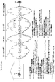
(第3実施例)
図2は本発明のインターネット電話システムにおける第1実施例に示した網以外の網を接続した図である。
【0066】
図2のシステム10では、各家庭等の送信側の既存電話端末11はVoIP制御端末12を介して2つの異なるルートで受信側の既存電話端末22に接続可能に構成されている。前記ルートの一方は、VoIP制御端末12から、レイヤー2のプロトコルによってサポートされているADSL網23、ISP(インターネット・サービス提供事業者:通称「プロバイダ」という)24、レイヤー3のプロトコルによってサポートされているIP網25、および既存電話網26を介して既存電話端末22に接続するルートであり、他方のルートは既存電話網26を介して既存電話端末22に接続するルートとなっている。
【0067】
VoIP制御端末12は、図示しない経路振り分け用のテーブルを有する。前記テーブルには、特番、例えば警察の110番、消防署の119番等が記憶されていて、これら特番を指定すると、直接既存電話網26の既存電話網の加入者交換機21に接続する経路を選択するように関係づけられている。
【0068】
前記ADSL網23は、順に、ADSL加入者終端装置(DSLAM)13、ADSL終端装置(BAS)14、ルータ(IPパケット転送装置)15を接続した配線構造を有する。
【0069】
前記ISPは、入力および出力ともルータ15(IPパケット転送装置)からなり、これら両ルータ15(IPパケット転送装置)を接続した配線構造を有する。
【0070】
IP網25は、加入者の認証と、IP電話の接続を制御する装置であるIP加入電話用制御装置17即ちSIP−プロキシ(Proxy)と、IP中継電話用制御装置18とをIP網25全体を制御するために備え、順に、ルータ(IPパケット転送装置)15、VoIP専用IPアクセス制御装置16、VoIPゲートウエイ19を接続した配線構造を有する。前記VoIPゲートウエイ19は、トランキングゲートウエイ(TG)とも云われ、ソフトスイッチで交換機機能を実現した構成を有する。
【0071】
前記VoIP専用IPアクセス制御装置16は、実際の通話している呼に関する音声パケット(RTP)だけを通す機能を持つ特殊な装置であり、IP網25の内部の装置17、18およびゲートウエイ19を他の網からアクセスできないようにする機能を持つ。
【0072】
IP加入電話用制御装置17は、加入者の認証と、IP電話の接続を制御する装置であり、SIPプロキシからなる。IP加入電話用制御装置17は、SIPサーバを構成するプロキシ(代理)サーバとロケーション・サーバを有し、IP電話がかけられると、以下のように動作する。
例えば、tokkyo.co.jpドメインの端末abcにいる氏名ABCが、patent.comドメインの端末xyzにいるXYZに電話をかけるとき、まず、ABCの端末abcから、patent.comドメインのSIPサーバであるsip.patent.comへ、XYZ@patent.com宛のINVITE(セッション参加要求)リクエストを送ると、プロキシー(代理)・サーバはXYZ@patent.comの本当のアドレスを調べるためにロケーション・サーバに照会し、それがXYZ@xyz.patent.comであることがわかると、プロキシー・サーバは、端末xyzに対してINVITEリクエストを送る。端末xyzで電話が鳴るので、xyzが電話に出ると、200 OKレスポンスがプロキシーサーバ経由でabcまで届き、これに対して端末abcからACK(確認応答)がプロキシー・サーバ経由でxyzまで届いて、通常のポートが開かれる。以下会話が続くが省略する。
【0073】
IP中継電話用制御装置18は、IP中継用電話サービス用の接続先を制御(トランスレータ)する機能を有する。
【0074】
VoIPゲートウエイ19は、既存電話網26の交換機と接続し、音声パケットを再生して、既存電話網26の交換機に流す機能を持つ。
【0075】
既存電話網26は、既存電話網の中継交換機20と既存電話網の加入者交換機21を接続する配線構造を有する。
【0076】
既存電話網26の中継交換機20は、他事業者と相互接続する交換機である。
【0077】
既存電話網26の加入者交換機21は、既存電話網26の加入者を直接収容する交換機である。
【0078】
この結果、送信側の既存電話端末11から受信側の既存電話端末22に発信するときの経路は次の2経路になる。
経路1:
送信側の既存電話端末11→VoIP制御端末12→ADSL加入者終端装置(DSLAM)13→ADSL終端装置(BAS)14→ルータ(IPパケット転送装置)15→ルータ(IPパケット転送装置)15→ルータ(IPパケット転送装置)15→ルータ(IPパケット転送装置)15→VoIP専用IPアクセス制御装置16→VoIPゲートウエイ19→既存電話網26の中継交換機20と既存電話網26の加入者交換機21→受信側の既存電話端末22の経路をとる。
パケットは、VoIP制御端末12で形成され、途中そのままで伝送され、VoIPゲートウエイ19で既存電話網の音声信号に変換される。
経路2:
送信側の既存電話端末11→VoIP制御端末12→既存電話網の加入者交換機21→受信側の既存電話端末22の経路をとる。
【0079】
(発信方路制御方法)
図3は第3実施例の場合の発信方路制御方法を示すシーケンス図である。
【0080】
図3では、VoIP制御端末が既存電話網に発信するか、VoIP側に発信するかを決定する方法を選択論理1〜3の3態様に分けて示す。
(1)選択論理1:
VoIP制御端末12には、予め、警察の110番、消防署の119番等および将来もIP電話で接続できない番号等の特番をテーブルに記憶してある。
アナログ電話機11が発信(090〜)すると、VoIP制御端末12はその発信を受け、宛先番号が前記特番であると判断したとき、既存電話網26の加入者交換機21へ発信(090〜)する。
(2)選択論理2:
IP加入電話用制御装置17には、IP電話サービス当初はサービスしていないが将来的にIP電話で接続可能になる番号、例えば、携帯電話番号(090〜、080〜、070〜)、フリーダイヤル番号(0120〜、0800〜)、国際電話番号(010〜)等、のテーブルを予め設けておく。
【0081】
IP加入電話用制御装置17は、かけられた番号が、IP電話でつなぐことが可能な番号か否かチェックし、将来的にIP電話でつなぐことが可能な番号だが、現在はつながっていない番号に対して、規制する機能を持つ。この規制する番号の場合には、「404 Not Found」というSIP信号を返す機能を持つ。
【0082】
VoIP制御端末12は、「404 Not Found」というSIP信号が返送されると、公衆電話回線からなる既存電話網26に対して再度発信する機能を持つ。前記「404 Not Found」以外のエラー信号では、既存電話網26に発信しないで、ビジートーンをアナログ電話機11側に聞かせる機能を持つ。
【0083】
アナログ電話機11がVoIP制御端末12へ、例えば携帯電話で発信(090〜)すると、VoIP制御端末12はADSL網23およびISP24を介してIP網25のIP加入電話用制御装置17にINVITEリクエスト(セッション参加要求)(090〜)信号を発信する。
【0084】
IP加入電話用制御装置17は、SIPプロトコルでサポートされ、前記INVITEリクエストを受け付けると、VoIP制御端末12へ認証要求(SIP信号407)を返送する。
【0085】
VoIP制御端末12は、認証要求(SIP信号407)に応じて、ID:パスワード等を含むINVITE(090〜)信号をIP加入電話用制御装置17へ発信する。
【0086】
IP加入電話用制御装置17は、かけられた番号が、IP電話でつなぐことが可能な番号か否かチェックし、将来的にIP電話でつなぐことが可能な番号だが、現在はつながっていない番号に対して、規制するために、接続不可、既存電話網への発信指示を伴う「404 Not Found」というSIP信号をVoIP制御端末12へ返す。
【0087】
VoIP制御端末12は、「404 Not Found」というSIP信号を受信すると、方路変更して、公衆電話回線からなる既存電話網26の加入者交換機21へ発信する。
(3)選択論理3:
アナログ電話機11がVoIP制御端末12へ、例えば携帯電話で発信(090〜)すると、VoIP制御端末12はADSL網23およびISP24を介してIP網25のIP加入電話用制御装置17にINVITEリクエスト(セッション参加要求)(090〜)信号を発信する。
【0088】
IP加入電話用制御装置17は、SIPプロトコルでサポートされ、前記INVITEリクエストを受け付けると、VoIP制御端末12へ認証要求(SIP信号407)を返送する。
【0089】
VoIP制御端末12は、認証要求(SIP信号407)に応じて、ID:パスワード等を含むINVITE(090〜)信号をIP加入電話用制御装置17へ発信する。
【0090】
IP加入電話用制御装置17は、かけられた番号が、IP電話でつなぐことが可能な番号か否か前記テーブルでチェックし、IP電話でつなぐことが可能な番号のとき、既存電話網26の加入者交換機21に発信(090〜)する。
【0091】
第3実施例の場合にも、IP加入電話用制御装置17が、IP網25を介して受信側のアナログ電話機22に呼び出しをかけるとき、送信側のアナログ電話機11に呼び出し音の前に呼び出し音とは異なる可聴音を送出し、IP網25経由での接続であることをユーザーに認識可能に表示することも可能である。
【0092】
(第3実施例の効果)
第3実施例は、IP網および既存電話網以外の網を介した接続であっても迂回に伴う方路変更がIP網側からの変更指示により行うことができ、その際、SIPプロトコルによりサポートするので、ユーザーにとって使い勝手のよいシステムになると共に、公衆電話回線からなる既存電話網との信号処理が良好になる。
【0093】
【発明の効果】
本発明は、少なくともSIPプロトコルによりサポートされたIP網を介して既存電話網に接続する構成としたので、迂回に伴う方路変更がIP網側からの変更指示により行うことが可能となる。その際、SIPプロトコルによりサポートするので、ユーザーにとって使い勝手のよいシステムになると共に、公衆電話回線からなる既存電話網との信号処理が良好になる。
【0094】
ユーザ宅に置かれたVoIP制御端末は、電話番号をどこに発信するかという展開データを変更する必要がなくなり、データを変更するための手間や、事業者側のコストを削減することが可能になる。
【0095】
また、IP網および既存電話網以外の網を介した接続構成であっても、迂回に伴う方路変更がIP網側からの変更指示により行うことが可能となる。
【0096】
また、IP加入電話用制御装置が、IP網を介して受信側のアナログ電話機に呼び出しをかけるとき、送信側のアナログ電話機に呼び出し音の前に呼び出し音とは異なる可聴音を送出し、IP網経由での接続であることをユーザーに認識可能に表示することも可能となる。
【図面の簡単な説明】
【図1】本発明の第1実施例のネットワーク構成図である。
【図2】本発明の第2実施例のネットワーク構成図である。
【図3】本発明のネットワークの接続シーケンスを示す図である。
【図4】従来の電話交換網とインターネットプロトコル網を結合した通信網接続装置を示す図である。
【符号の説明】
1 システム
2、7 既存電話端末
3、12 VoIP制御端末
4 IP電話制御装置
5 IP網
6 既存電話網
11、22 アナログ電話機(既存電話端末)
13 ADSL加入者終端装置
14 ADSL加入者終端装置
15 ルータ
16 VoIP専用IPアクセス制御装置
17 IP加入電話用制御装置
18 IP中継電話用制御装置
19 VoIPゲートウエイ
20 既存電話網中継交換機
21 既存電話網加入者交換機
23 ADSL網
24 ISP
25 IP網
26 既存電話網[0001]
TECHNICAL FIELD OF THE INVENTION
The present invention relates to an existing telephone on a calling side through a VoIP (Voice over IP: abbreviation for passing voice by Internet protocol) control terminal for passing voice through an IP (Internet protocol) network such as the Internet or an intranet. The present invention relates to an IP telephone system for connecting a terminal and an existing telephone network on a receiving side directly or via an IP network (digital leased line, frame relay, the Internet).
[0002]
[Prior art]
An IP subscriber telephone system via an IP network can reduce communication costs by efficiently using the network area of the network. Therefore, since the IP subscriber telephone service using this system is via the IP network which is not charged according to the distance in the network, it is compared with the telephone service which is charged according to the distance of the conventional telephone switching network. However, low-cost, unprecedented additional services can be provided, and rapid development is expected in the future.
[0003]
FIG. 4 is a diagram showing a conventional communication network connection device (for example, see Patent Document 1) in which a telephone exchange network and an Internet protocol network are connected.
[0004]
In FIG. 4, when the transmitting telephone terminal 74 dials the receiving telephone terminal 79, the exchange 70 analyzes the dial number, determines a route to the child voice gateway 64, and activates the child voice gateway 64. , Send the dialed digits. When the child voice gateway 64 receives the dialed digit, it transmits a destination inquiry message to the
[0005]
The IP network of this IP telephone uses H.264 to use an IP address. H.323 is supported by the TCP / IP protocol. On the other hand, VoIP terminals (child voice gateway 64 and parent voice gateway 60) connected to the public telephone line GSTN must be connected to SS7 which is out-band signaling for call connection and routing (path control) on the GSTN side. So the outband signaling protocol must be completely converted. However, H. Since the protocol supported by H.323 is complicated, it is not easy to develop a device and a new application.
[0006]
SIP (Session Initiation Protocol) is a protocol that facilitates application development.
[0007]
This SIP protocol is a protocol specified by RFC3261 by an IETF (Internet Engineering Task Force) organization.
[0008]
Hereinafter, characteristics of the SIP protocol will be described.
[0009]
In order to realize a telephone service, it is necessary to set operating parameters required for a telephone call to an IP telephone before transmitting voice. The necessary operation parameters include (a) a coding method of a voice signal, (b) a transport address (IP address and port number) used for transmission, (c) a necessary network bandwidth, and (d) start and accept a call. , And (e) information such as the location of the called party.
[0010]
SIP is used as a mechanism (signaling) for exchanging such information between IP telephones (between Internet telephones) and between an IP telephone and a service providing server in a network.
[0011]
However, since not all of these are defined in the SIP standard, an existing protocol, an address expression of an e-mail type, and a code of HTTP (hypertext transfer protocol) are used.
[0012]
SIP starts and ends a session, but does not care about the contents of the session. That is, since SIP has a mechanism that uses SDP (Session Description Protocol) that defines session information, the protocol does not include information about the session. This makes it easy to implement a server function and increase the number of clients that provide services. In other words, by using SDP as needed without having session information, the amount of server memory required for processing each client is reduced, so that services can be provided to more clients. it can.
[0013]
In a terminal protocol configuration based on SIP, RTP (Real Time Transmission Protocol) packets of audio and video signals are transmitted by UDP (User Datagram Protocol) / IP. TCP support is optional. H. The protocol of the H.323 terminal is significantly different from the necessity of supporting TCP.
[0014]
A communication procedure of the SIP, particularly, a direct communication procedure between terminals will be described.
(1) First, the calling side picks up the receiver and dials the telephone number. Then, an “INVITE” request (a session participation request) is sent to the called side.
(2) When the "INVITE" request arrives at the called side, a "100 Trying" response is sent from the called side to the calling side.
(3) Next, a "180 Ringing" response is sent from the called side to the calling side. When the receiver picks up the receiver, a "2000K" response is sent.
(4) When an ACK (acknowledgement) is sent from the calling side, a port for communication is opened and a call can be made.
(5) To end the call, send a “BYE” message. The "BYE" message can be issued from either the calling side or the called side.
The "INVITE" request is a request to participate in a session, and includes (1) the address of the called side, (2) the address of the calling side, and (3) the definition of the media used for the call.
[0015]
Instead of a telephone number, an e-mail address type destination indicator is used for the calling and called party addresses. For the first three digits such as 100Trying and 180Ringing, those conforming to a three-digit response code system used in HTTP are used.
[0016]
When performing communication using the SIP server, the user terminal registers its location in the SIP server by a REGISTER (registration) request. Further, the user terminal changes (redirects) the destination of the message to the destination by changing the registration information. This SIP server can be a proxy server or a redirect server.
[0017]
(SIP message format)
In SIP, a URL (Uniform Resource Locator) is used to specify the address of the calling side or called side of a call, and is referred to as SIP-URL. The URL has a format for specifying and accessing addresses of resources (computer resources) distributed on the Internet. The SIP URL follows the same rules as the URL that specifies the address of a WWW page.
[0018]
The URL indicating the SIP-URL starts with “sip:”. The next field is the user's identifier. As the identifier, not only the user name but also a telephone number can be used. After @, a domain name or an IP address can be used as a host name of a terminal or a server that provides a SIP service.
[0019]
(SIP message format)
SIP messages are divided into requests (requests) and responses (responses). The request is a message sent from a user agent client (UAC) that makes a telephone call (IP telephone) to a SIP server. On the other hand, the response is a response message returned from the user agent server (UAS) or the SIP server to the UAC.
[0020]
(request)
The start line of the request includes INVITE, ACK, and the like, and includes a SIP-URL as necessary. This SIP-URL is an address specification that includes the host name as far as it can be known. On the other hand, the message header contains user information on the calling side, user information on the called side, and a number unique to the call. The message body contains session information based on SDP (session description protocol). The session information includes, for example, a type of a supported voice codec and a bit rate used for a call.
[0021]
SIP message headers are configured according to the same rules as email headers. "<>" In the message corresponds to a mail address.
[0022]
(response)
The start line of the response contains a three digit status code and a brief description. The message header and the message body are the same as in the request.
[0023]
(Features of SIP)
It is said that SIP is a light text protocol and easy to implement. In general, SIP uses existing Internet technology, and therefore has good compatibility with WWW. In the SIP, the storage of the state of the SIP server can be made zero, that is, the server does not have to store the history of the change of the communication state. It is superior in extensibility as compared with the H.245 state transition type protocol.
[0024]
Regarding the connection with the PSTN (general public telephone line), the VoIP terminal needs to be connected to SS7 which is out-band signaling for call connection and routing (path control) on the PSTN side. Out-band signaling is a method of separately exchanging a call control signal and a voice call signal. SIP is designed in consideration of compatibility with SS7's ISUP (protocol for transmitting information for connecting a voice communication line).
[0025]
In the protocol expression, in the case of SIP, a text expression is taken, and the result of character conversion can be read as a message itself. For this reason, debugging and maintenance when an error occurs are facilitated, and mounting is facilitated.
[0026]
(Current status)
At present, there is no system using SIP as an IP telephone protocol. The present invention focuses on this point.
[0027]
[Patent Document 1] Japanese Patent Application Laid-Open No. 2001-298481
[0028]
[Problems to be solved by the invention]
In order to ensure the same convenience as conventional telephone services, numbers and services that cannot be connected are transmitted using the conventional telephone network, and numbers and services that can be provided as IP telephones are transmitted to the IP network. We need a mechanism to transmit.
[0029]
At that time, since the call charge is different between the case where the call is made using the IP network and the case where the call is made using the existing telephone network, the user is clearly notified which call is used for each call. Is considered to be one of the needs of the user. In other words, it has been recognized that it is necessary to solve the problem that a long telephone call made to be a low-cost IP telephone is actually made via the existing telephone network, so that a conventional telephone fee charged according to the distance is charged. I was
[0030]
There is also a need to employ more convenient protocols to support the public telephone network in IP telephony.
[0031]
In view of the above problems, it is an object of the present invention to determine whether or not the Internet protocol network can be connected and whether or not the service can be provided. The object of the present invention is to provide an internet protocol telephone system.
[0032]
Another object of the present invention is to determine whether the Internet protocol network can be connected or whether the service is a service that can be provided, and make a call using the Internet protocol network. It is an object of the present invention to provide an Internet protocol telephone system for clearly notifying a user that a call has been made using a telephone network.
[0033]
Another object of the present invention is to provide an Internet protocol telephone which employs an optimal protocol and which can be connected using an existing telephone network comprising a public switched telephone network when it is determined that the number cannot be connected in the Internet protocol network. It is to provide a system.
[0034]
[Means for Solving the Problems]
The present invention employs the following solutions in order to achieve the above objects.
(1) An Internet protocol telephone system in which an existing telephone terminal is connected to an existing telephone network directly and via an Internet protocol network after passing through a VoIP control terminal. The Internet protocol network notifies a number that can be provided as an Internet protocol network supported by the SIP protocol and a service and a number that cannot be provided.
(2) In the Internet protocol telephone system, the existing telephone terminal is connected to the existing telephone network via the VoIP control terminal, then through the ADSL network, the ISP, and the Internet protocol network, and is connected via the VoIP control terminal. An Internet protocol telephone system directly connected to the existing telephone network, wherein the Internet protocol network notifies the VoIP control terminal of a number that can be provided as the Internet protocol network and a service and a number that cannot be provided. It is characterized by doing.
(3) In the Internet protocol telephone system according to the above (1) or (2), when the existing telephone terminal is making a call to the existing telephone network via the Internet protocol network, the Internet protocol network is on the originating side. The transmission state is notified to the user via the existing telephone terminal.
[0035]
BEST MODE FOR CARRYING OUT THE INVENTION
Hereinafter, embodiments of the present invention will be described in detail with reference to the drawings.
[0036]
(First embodiment)
FIG. 1 is a diagram showing a first embodiment of the Internet telephone system of the present invention. Main components will be described.
[0037]
(VoIP control terminal)
The VoIP control terminal 3 that performs the control operation of the present invention is connected to the existing
[0038]
(IP telephone controller)
On the side of the
[0039]
As a method of determining (telephone) numbers connectable as the
[0040]
Therefore, the present invention adopts a method in which the
[0041]
In the system 1 of FIG. 1, the existing
[0042]
The VoIP control terminal 3 has a connection interface to the
[0043]
The
[0044]
(Automatic PSTN [Public switching telephone network <subscriber telephone network>] detour function)
The VoIP control terminal 3 has, in a table, numbers to be transmitted to the PSTN composed of the existing telephone network 6 and the like (numbers that will not be changed in the future). send.
[0045]
When the user turns a number not present in the table on the VoIP control terminal 3 side from the existing
[0046]
The VoIP control terminal 3 that has received the signal “404 NotFound” transmits the same number to the PSTN composed of the existing telephone network 6 and the like.
[0047]
In order to guarantee the above operation, the VoIP control terminal 3 first transmits to the
[0048]
Returning the signal "404 NotFound" on the
[0049]
(VoIP outgoing call explicit function)
The VoIP outgoing call explicit function means a function of displaying to the user of the existing
[0050]
The VoIP control terminal 3 emits an audible VoIP transmission sound (phonetic “pupup”) before an RBT (ringing sound (phonetic “Rururu”)) when VoIP is transmitted by the VoIP calling explicit function.
[0051]
The above-mentioned “when a VoIP call is made” refers to a state in which the VoIP control terminal 3 is calling another party in the existing telephone network 6 connected beyond the
[0052]
The VoIP outgoing audible tone is a tone in which a 400 Hz sound is emitted for 150 msec and silence is repeated for 150 msec.
[0053]
(Connection process)
With reference to FIG. 1, a connection process to the existing telephone terminal 7 on the receiving side of the present invention will be described.
[0054]
-Connection process start-
{Circle around (1)} Dial the destination number from the existing
{Circle around (2)} — The VoIP control terminal 3 transmits a connection request signal to the other party in the existing telephone network 6 (including a telephone, a PHS, a mobile telephone, etc.) to the IP network 5 (step 2).
{Circle around (3)} The IP telephone control device 4 holds at least a list of existing telephone numbers to which connection can be made in a translator table or the like, and when a connection request is made, determines whether or not the destination can be connected via the
In the case of a connectable number or a service that can be provided, a connection request signal is transmitted to the existing telephone terminal 7 of the receiving party (step S4).
{Circle around (3)} − On the other hand, the IP telephone control device 4 determines whether or not the existing telephone terminal 7 of the receiving party can be connected via the IP network by using the table or the like (step S3).
If it is determined that the number or service cannot be connected, the fact is notified to the VoIP control terminal 3 by the SIP signal (step S5).
(4) Upon receiving the notification, the VoIP control terminal 3 transmits a connection request to the existing telephone network (step S6).
[0055]
−End of connection process−
(Effect of the first embodiment)
The IP telephone control device 4 of the
[0056]
In addition, since it is supported by the SIP protocol, the processing procedure is simplified.
[0057]
(Second embodiment)
Referring to FIG. 1, a connection processing procedure for notifying a transmitter of whether or not the connection state is via the IP network will be schematically described.
[0058]
-Connection process start-
{Circle around (1)} Dial the destination number of the existing telephone terminal 7 from the existing
(2)-A connection request signal to the destination number of the existing telephone terminal 7 in the existing telephone network 6 (including a telephone, a PHS, a mobile telephone, etc.) dialed from the VoIP control terminal 3 is transmitted to the IP network 5 ( Step 2).
{Circle around (3)} The IP telephone control device 4 in the
In the case of a connectable number or a service that can be provided, a connection request signal is transmitted to the destination of the existing telephone terminal 7 (step S4).
[0059]
-When the called party is ringing (that is, when the called party of the existing telephone terminal 7 in the existing telephone network 6 connected to the end of the
[0060]
The VoIP control terminal 3 performs “P” and “P” three times so that the user who is talking on the existing
[0061]
After the VoIP control terminal 3 returns the VoIP calling audible sound, the VoIP control terminal 3 returns an RBT (ringing sound (sounding “Rururu”)) to the user who is talking on the existing telephone terminal 2 (step S7).
{Circle around (3)} — On the other hand, the IP telephone control device 4 determines whether or not the receiving party can be connected via the
If it is determined that the connection cannot be provided or the service cannot be provided, this is notified to the VoIP control terminal 3 by the SIP signal (step S8).
{Circle around (4)} Upon receiving the notification, the VoIP control terminal 3 transmits a connection request to the existing telephone network 6 (step S9).
[0062]
In response to the connection request, the destination of the existing telephone terminal 7 in the existing telephone network 6 returns an RBT to the VoIP control terminal 3 (step S10).
[0063]
-Further, the VoIP control terminal 3 returns an RBT to the transmission destination of the existing telephone terminal 2 (step S11).
[0064]
−End of connection process−
The above operation is
(A) When the telephone line is connected via the IP network (routes (1) → (2) → (3) in the figure)
An audible tone different from the ringing tone is transmitted before the ringing tone, and the user can recognize that the connection is via the IP network.
(B) When connecting via the existing telephone network (routes (1) → (2) → (3) ` → (4) in the figure)
As in the case of the existing telephone, only the ringing tone is transmitted at the time of calling the other party, and the user can recognize that the connection is established via the existing telephone network.
[0065]
(Effect of Second Embodiment)
When calling the other party of the existing telephone terminal 7 in the existing telephone network 6 connected to the end of the
(Third embodiment)
FIG. 2 is a diagram in which networks other than those shown in the first embodiment in the Internet telephone system of the present invention are connected.
[0066]
In the
[0067]
The
[0068]
The ADSL network 23 has a wiring structure in which an ADSL subscriber terminating device (DSLAM) 13, an ADSL terminating device (BAS) 14, and a router (IP packet transfer device) 15 are connected in this order.
[0069]
The ISP comprises a router 15 (IP packet transfer device) for both input and output, and has a wiring structure connecting both routers 15 (IP packet transfer device).
[0070]
The
[0071]
The VoIP dedicated IP
[0072]
The IP subscriber
For example, tokkyo. co. The name ABC at the terminal abc of the jp domain is a patent. When making a call to XYZ at the terminal xyz of the com domain, first, the ABC. com domain SIP server sip. patent. com, XYZ @ patent. com sends an INVITE (session join request) request to the proxy server (XYZ@patent.com). com queries the location server to find out the real address of XYZ@xyz.com. patent. com, the proxy server sends an INVITE request to terminal xyz. Since the phone rings at terminal xyz, when xyz answers the phone, a 200 OK response arrives at abc via the proxy server, whereas an ACK (acknowledgment) from terminal abc arrives at xyz via the proxy server, Normal ports are opened. The conversation continues below, but is omitted.
[0073]
The IP relay
[0074]
The
[0075]
The existing telephone network 26 has a wiring structure for connecting the
[0076]
The
[0077]
The
[0078]
As a result, the following two routes are used when transmitting from the existing
Route 1:
Existing
The packet is formed by the
Route 2:
The route is established from the existing
[0079]
(Transmission route control method)
FIG. 3 is a sequence diagram showing a transmission route control method in the case of the third embodiment.
[0080]
FIG. 3 shows a method of determining whether the VoIP control terminal transmits to the existing telephone network or transmits to the VoIP side in three modes of selection logics 1 to 3.
(1) Selection logic 1:
The
When the
(2) Selection logic 2:
The IP subscriber
[0081]
The IP subscriber
[0082]
When the SIP signal “404 Not Found” is returned, the
[0083]
When the
[0084]
The IP subscriber
[0085]
In response to the authentication request (SIP signal 407), the
[0086]
The IP subscriber
[0087]
Upon receiving the SIP signal “404 Not Found”, the
(3) Selection logic 3:
When the
[0088]
The IP subscriber
[0089]
In response to the authentication request (SIP signal 407), the
[0090]
The IP subscriber
[0091]
Also in the case of the third embodiment, when the IP subscriber
[0092]
(Effect of Third Embodiment)
In the third embodiment, even if the connection is made via a network other than the IP network and the existing telephone network, the route change accompanying the detour can be performed by a change instruction from the IP network side. Therefore, the system is easy to use for the user, and the signal processing with the existing telephone network including the public telephone line is improved.
[0093]
【The invention's effect】
Since the present invention is configured to connect to the existing telephone network via at least the IP network supported by the SIP protocol, it is possible to perform a route change accompanying the detour by a change instruction from the IP network side. At this time, since the system is supported by the SIP protocol, the system is easy to use for the user, and the signal processing with the existing telephone network including the public telephone line is improved.
[0094]
The VoIP control terminal placed at the user's home does not need to change the development data indicating where to send the telephone number, and can reduce the trouble of changing the data and the cost of the business operator. .
[0095]
Further, even in a connection configuration via a network other than the IP network and the existing telephone network, it is possible to perform a route change accompanying the detour by a change instruction from the IP network side.
[0096]
Further, when the control device for the IP subscriber telephone calls the analog telephone on the receiving side via the IP network, it sends an audible tone different from the ringing tone to the analog telephone on the transmitting side before the ringing tone. It is also possible to display to the user that the connection is made via the Internet.
[Brief description of the drawings]
FIG. 1 is a network configuration diagram of a first embodiment of the present invention.
FIG. 2 is a diagram illustrating a network configuration according to a second embodiment of the present invention;
FIG. 3 is a diagram showing a connection sequence of a network according to the present invention.
FIG. 4 is a diagram showing a conventional communication network connection device that combines a telephone exchange network and an Internet protocol network.
[Explanation of symbols]
1 system
2, 7 Existing telephone terminals
3,12 VoIP control terminal
4 IP telephone controller
5 IP network
6 Existing telephone network
11,22 Analog telephone (existing telephone terminal)
13 ADSL subscriber termination equipment
14 ADSL subscriber termination equipment
15 Router
16 VoIP Dedicated IP Access Controller
17 IP telephone control system
18 Control device for IP relay telephone
19 VoIP Gateway
20 Existing telephone network relay exchange
21 Existing telephone network subscriber exchange
23 ADSL network
24 ISP
25 IP network
26 Existing Telephone Network
Claims (3)
Priority Applications (1)
| Application Number | Priority Date | Filing Date | Title |
|---|---|---|---|
| JP2003007746A JP2004222013A (en) | 2003-01-16 | 2003-01-16 | Internet protocol telephony sistem |
Applications Claiming Priority (1)
| Application Number | Priority Date | Filing Date | Title |
|---|---|---|---|
| JP2003007746A JP2004222013A (en) | 2003-01-16 | 2003-01-16 | Internet protocol telephony sistem |
Publications (1)
| Publication Number | Publication Date |
|---|---|
| JP2004222013A true JP2004222013A (en) | 2004-08-05 |
Family
ID=32897750
Family Applications (1)
| Application Number | Title | Priority Date | Filing Date |
|---|---|---|---|
| JP2003007746A Pending JP2004222013A (en) | 2003-01-16 | 2003-01-16 | Internet protocol telephony sistem |
Country Status (1)
| Country | Link |
|---|---|
| JP (1) | JP2004222013A (en) |
Cited By (3)
| Publication number | Priority date | Publication date | Assignee | Title |
|---|---|---|---|---|
| AU2004200255B2 (en) * | 2003-01-27 | 2005-09-22 | Nec Platforms, Ltd. | Internet Telephone System, Call Connection Controller, Terminal Association Method Used Therein and Its Program |
| WO2005096609A1 (en) * | 2004-03-30 | 2005-10-13 | Softbank Bb Corp. | Communication network system, access gateway, and control method thereof |
| JP2008205874A (en) * | 2007-02-21 | 2008-09-04 | Hitachi Communication Technologies Ltd | Gateway device and call relaying method |
-
2003
- 2003-01-16 JP JP2003007746A patent/JP2004222013A/en active Pending
Cited By (3)
| Publication number | Priority date | Publication date | Assignee | Title |
|---|---|---|---|---|
| AU2004200255B2 (en) * | 2003-01-27 | 2005-09-22 | Nec Platforms, Ltd. | Internet Telephone System, Call Connection Controller, Terminal Association Method Used Therein and Its Program |
| WO2005096609A1 (en) * | 2004-03-30 | 2005-10-13 | Softbank Bb Corp. | Communication network system, access gateway, and control method thereof |
| JP2008205874A (en) * | 2007-02-21 | 2008-09-04 | Hitachi Communication Technologies Ltd | Gateway device and call relaying method |
Similar Documents
| Publication | Publication Date | Title |
|---|---|---|
| AU774880B2 (en) | Method of and system for providing intelligent network control services in IP telephony | |
| US8130923B2 (en) | Method and apparatus for providing emergency calls to a disabled endpoint device | |
| EP2012516B1 (en) | Customised playback telephony services | |
| US20090285204A1 (en) | Recursive query for communications network data | |
| US20080240375A1 (en) | Method Of Processing Multiple Ring Back Tone In Voice Service Application Based On Sip Fork | |
| JP3873048B2 (en) | Ringback tone transmission method, terminal, ringback tone generation method, and system for generating ringback tone | |
| TW200304296A (en) | Apparatus and method for computer telephone integration in parkcet switched telephone networks | |
| JP2009500990A (en) | Use of PSTN to communicate IP addresses for point-to-point text, voice, video or data communications | |
| KR100602638B1 (en) | The method for VoIP-UMS system access | |
| JP2004524755A (en) | VoIP system | |
| CA2469213C (en) | System and method for integrating multimedia services with traditional telephony via different networks | |
| US7738445B2 (en) | Combined H.450.2 and SIP call transfer | |
| WO2004032471A1 (en) | Multimedia pickup service | |
| CA2544154A1 (en) | Method and apparatus for enabling dynamic protocol interworking resolution with diverse endpoints | |
| KR100969458B1 (en) | System and its method for multimedia ring back service using session initiation protocol | |
| US7860224B1 (en) | Method and apparatus for providing a voicemail notification | |
| JP4564881B2 (en) | Voice communication system | |
| Cisco | Session Initiation Protocol (SIP) for VoIP | |
| JP2004222013A (en) | Internet protocol telephony sistem | |
| US7539177B2 (en) | Call hold/terminal portability in H.323/ISUP-BICC-SIP networks | |
| KR100809398B1 (en) | Method and system for transmitting SMS for VoIP service supproting Multi-protocol | |
| JP2005269165A (en) | Ip phone | |
| JP2006005501A (en) | VoIP NETWORK, MEDIA PROXY SERVER, AND EXTRA SERVICE PROVIDING METHOD FOR USE THEREIN | |
| JP2004147137A (en) | Communication system | |
| US7965700B1 (en) | Method and apparatus for enabling service indicators in a call control element |
Legal Events
| Date | Code | Title | Description |
|---|---|---|---|
| RD04 | Notification of resignation of power of attorney |
Free format text: JAPANESE INTERMEDIATE CODE: A7424 Effective date: 20050728 |
|
| A521 | Written amendment |
Free format text: JAPANESE INTERMEDIATE CODE: A523 Effective date: 20050928 |
|
| A521 | Written amendment |
Free format text: JAPANESE INTERMEDIATE CODE: A523 Effective date: 20051025 |
|
| A521 | Written amendment |
Free format text: JAPANESE INTERMEDIATE CODE: A821 Effective date: 20051026 |
|
| RD02 | Notification of acceptance of power of attorney |
Free format text: JAPANESE INTERMEDIATE CODE: A7422 Effective date: 20051026 |
|
| A621 | Written request for application examination |
Free format text: JAPANESE INTERMEDIATE CODE: A621 Effective date: 20060106 |
|
| A977 | Report on retrieval |
Free format text: JAPANESE INTERMEDIATE CODE: A971007 Effective date: 20071025 |
|
| A131 | Notification of reasons for refusal |
Free format text: JAPANESE INTERMEDIATE CODE: A131 Effective date: 20071121 |
|
| A02 | Decision of refusal |
Free format text: JAPANESE INTERMEDIATE CODE: A02 Effective date: 20080311 |