JP2004220679A - Reproducing device - Google Patents
Reproducing device Download PDFInfo
- Publication number
- JP2004220679A JP2004220679A JP2003005851A JP2003005851A JP2004220679A JP 2004220679 A JP2004220679 A JP 2004220679A JP 2003005851 A JP2003005851 A JP 2003005851A JP 2003005851 A JP2003005851 A JP 2003005851A JP 2004220679 A JP2004220679 A JP 2004220679A
- Authority
- JP
- Japan
- Prior art keywords
- image signal
- screen
- moving image
- reproduction
- instruction
- Prior art date
- Legal status (The legal status is an assumption and is not a legal conclusion. Google has not performed a legal analysis and makes no representation as to the accuracy of the status listed.)
- Pending
Links
Images


Abstract
Description
【0001】
【発明の属する技術分野】
本発明は再生装置に関し、特に動画像の再生動作の制御に関する。
【0002】
【従来の技術】
従来、VTRなどで再生した動画像の中の一画面を選択して印刷するビデオプリンタが知られている。
【0003】
この様なビデオプリンタを用いてプリントを行う場合、ユーザは、VTRを操作して動画像を再生し、再生された動画像を確認しながら所望の画面が再生された時点で動画像の再生を一時停止して、静止画像信号をケーブルなどを介してプリンタに送信し、印刷する。
【0004】
この種のビデオプリンタシステムが、特開平6−245179号公報に開示されている。
【0005】
【特許文献1】
特開平6−245179号公報
【0006】
【発明が解決しようとする課題】
しかし、前述の様に動画像を確認しながら所望の画面にて一時停止することは困難であり、通常は、巻き戻しや早送り、再生、一時停止などの操作を繰り返して所望の画面を探し、選択しなければならない。
【0007】
この様な操作は、機械操作に不慣れなユーザにとっては非常に困難な作業であり、また、所望の画面を選択するために非常に時間がかかってしまう。
【0008】
本発明はこの様な問題を解決することを目的とする。
【0009】
本発明の他の目的は、動画像を再生しながら、簡単な操作で容易に所望の画面を選択可能とする処にある。
【0010】
【課題を解決するための手段】
前述の如き課題を解決するため、本発明においては、記録媒体から動画像信号を再生する再生手段と、指示手段と、前記動画像信号の再生中の前記指示手段による指示に応じて、前記指示に対応した第1の画面の所定期間前の第2の画面より通常再生速度よりも遅い速度で前記動画像信号を再生するよう前記再生手段を制御する制御手段とを備える構成とした。
【0011】
【発明の実施の形態】
以下、本発明の実施形態を説明する。
【0012】
本形態では、ビデオカメラとビデオプリンタとをケーブルなどで接続して所望の画面を印刷するシステムに対して本発明を適用した場合について説明する。
【0013】
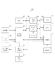
図1は本発明が適用されるビデオカメラ100の構成を示す図である。
【0014】
図1において、101は撮像部、102はマイクユニットであり、それぞれ動画像信号と音声信号を出力する。103は符号化処理部であり、撮影モードでは撮像部101からの動画像信号とマイク102からの音声信号とを符号化し、再生モードでは再生された画像信号と音声信号を復号する。104は表示制御部であり、表示パネル105に対して画像信号を出力する。105は表示パネルであり、本形態では液晶表示デバイスを用いる。
【0015】
106はデータバス、107はRAMであり、符号化処理部103による符号化、復号化処理などにおいて用いられる。107はディスクI/Fであり、ディスクDに対して画像データと音声データを記録再生する。また、本形態ではディスクDとして、DVDなどの光磁気ディスクを用いる。108は外部I/Fであり、本形態では接続された機器に対して画像データのほか、各種のデジタルデータを送受信する。本形態では、IEEE1394フォーマットにてデータの送受信を行い、後述の様に、ケーブルを介してビデオプリンタと接続する。
【0016】
109は制御バス、110はROM、111はRAMである。ROM110は制御部112内のマイクロコンピュータにて用いる制御プログラムなど、各種のデータを記憶している。111は制御部112の処理に用いられる。112は制御部であり、操作スイッチ113からの指示に従ってビデオカメラ100の各部の動作を制御する。113は操作部であり、動画撮影の開始、停止トリガ、再生や早送り、巻き戻しキー、撮影モードと再生モードとを切り替えるためのモードスイッチなど、各種のスイッチを有する。114はテレビ信号処理部であり、外部のテレビモニタなどの外部機器に対して符号化処理部から出力される画像、音声信号を出力すると共に、外部のビデオカメラなどから画像、音声信号を入力する。
【0017】
次に、図1のビデオカメラ100を用いたプリントシステムについて説明する。
【0018】
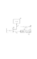
図2は本発明が適用されるプリントシステムの構成を示す図である。図2では、ビデオカメラ100のテレビ信号処理部114とモニタMとをケーブルC1で接続し、ビデオカメラ100のデジタルI/F108とプリンタ200のデジタルI/F201とをケーブルC2で接続している。
【0019】
そして、ディスクDから再生された動画像信号をモニタMに出力して表示すると共に、再生された動画像信号中の一画面を静止画像信号としてプリンタ200に出力する。
【0020】
プリンタ200は周知のプリント機能を持ち、ビデオカメラ100から送られた画像信号に応じた画像をプリントする。また、プリンタ200は、ビデオカメラ100のデジタルI/F114と同様の機能を持つデジタルI/F201を有し、後述の様に、ダイレクトプリントキー203の操作に応じた制御信号をビデオカメラ100に出力すると共に、ビデオカメラ100から出力された画像信号を入力する。202は操作スイッチであり、ダイレクトプリントキー203の他、電源スイッチなど各種のスイッチを有する。
【0021】
次に、図2のシステムにおいて、ディスクDから再生された動画像信号中の所望の画面を選択し、プリントするダイレクトプリント機能の動作について説明する。
【0022】
ダイレクトプリントを行う場合、ユーザはまず、図1の操作部114を操作して、ディスクDからの動画像信号の再生を指示する。制御部112はこの再生指示に従ってディスクI/F107を制御し、ディスクDに記録されている動画像信号を再生する。符号化処理部103は制御部112からの再生開始の指示に応じて、ディスクI/F107により再生された動画像信号を復号し、テレビ信号処理部114を介してモニタMに出力する。
【0023】
ユーザはこの状態でモニタMに表示されている再生画像を見ながら、所望の画面の再生タイミングにおいてプリンタ200のダイレクトプリントキー203を操作する。ダイレクトプリントキー203が操作されると、デジタルI/F201からダイレクトプリント要求を示すコマンドをビデオカメラ100のデジタルI/F108に対して出力する。
【0024】
ビデオカメラ100のデジタルI/F109はこのダイレクトプリント要求を受けると、制御バス110を介して制御部113に出力する。制御部113は動画像信号の再生中にこのダイレクトプリント要求を受けると、現在の動画像信号の再生位置をRAM111に格納すると共に、現在の再生位置から所定期間(フレーム数)、例えば本形態では10秒程度前の位置より、通常再生速度よりも遅い速度にて動画像信号を再生するようディスクI/F107を制御する。
【0025】
なお、本形態では、再生された動画像信号に付加されているタイムコードを検出し、このタイムコードを再生位置情報として用いる。
【0026】
ディスクI/F107は制御部112からの制御信号に応じて、現在の再生位置から所定期間前の位置より、通常再生速度よりも遅い速度にて動画像信号を再生する。符号化処理部103はこの様に低速で再生された動画像信号を復号し、テレビ信号処理部114を介してモニタMに出力する。この結果、モニタMには、ユーザがダイレクトプリントキー203を操作した時点から所定期間前の画面より、スロー再生された動画像信号が表示される。
【0027】
この様にスロー再生された動画像を確認しながら、ユーザが再びダイレクトプリントキー203を操作すると、デジタルI/F201はフレーム確定コマンドを出力する。
【0028】
ビデオカメラ100のデジタルI/F114はこのフレーム確定コマンドを入力し、制御部112に出力する。制御部112はスロー再生中にフレーム確定コマンドを入力すると、フレーム確定コマンドが入力された時点で再生されている画面の画像信号をプリント候補の静止画像信号としてRAM107に記憶するようディスクI/F108を制御する。ディスクI/Fは制御部112からの指示に従い、指定された画面の画像信号をディスクDから再生し、RAM107に記憶する。そして、デジタルI/F110は、このRAM107に記憶された一画面の画像信号をプリント候補の静止画像信号としてプリンタ200に出力する。
【0029】
また、符号化処理部103は、デジタルI/F110よりプリント候補の静止画像信号の送信が完了するまで、RAM107に記憶された画面の画像信号をテレビ信号処理部115から繰り返し出力することで、再生一時停止状態とする。
【0030】
なお、本形態では、動画像信号をMPEG方式に従い符号化して記録している。MPEG方式では、フレーム内符号化処理とフレーム間符号化処理とを組み合わせて画像信号を符号化しており、フレーム間符号化処理は参照フレームの画像信号と自身のフレームとの差分データを符号化しているため、単独では復号できない。そのため、本形態では、プリント候補として指定された画面がフレーム間符号化された画面である場合には、この画面に最も近いフレーム内符号化された画面の画像信号をプリント候補の画像信号として選択、再生している。
【0031】
プリンタ200では、以上の操作の結果ビデオカメラ100から送信されたプリント候補の静止画像信号を入力し、この静止画像信号を復号した後プリントする。
【0032】
以上の様子を図3を用いて説明する。
【0033】
図3はダイレクトプリント処理において再生される画像の様子を示す図である。
【0034】
301はディスクDから再生される動画像の様子を示しており、矢印302の方向に再生される。動画像301の再生中に、303のタイミングでダイレクトプリントキー203が操作され、ダイレクトプリント要求を受けると、303に対応した位置から所定期間Fだけ前の位置304から、通常再生速度よりも遅い速度にて動画像を再生する。
【0035】
そして、305〜309で示す様に、この期間Fの各フレームがスロー再生される。
【0036】
ここで、スロー再生期間中にダイレクトプリントキー203が操作されずに303に対応した位置まで再生し終えた場合、制御部112は再び304の位置からスロー再生を繰り返すようディスクI/F108を制御する。
【0037】
以上の様なプリンタ200とビデオカメラ100の動作タイミングの様子を図42示す。
【0038】
ビデオカメラ100による動画像の再生中に、401においてプリンタ200のダイレクトプリントキー203が操作されると、ダイレクトプリント要求402がビデオカメラ100に対して出力される。ビデオカメラ100ではこのダイレクトプリント要求402に対する応答403をプリンタ200に対して出力した後、ダイレクトプリント要求があった時点から所定期間前の位置よりスロー再生404を開始する。その後、405においてダイレクトプリントキー203が操作されると、フレーム選択要求406がビデオカメラ100に対して出力される。ビデオカメラ100ではこのフレーム選択要求406を受けた時点で再生していた画面の画像信号408をデジタルI/F110よりプリンタ200に送信すると共に、409の期間再生画面を一時停止する。そして、プリンタ200より静止画像信号の受信完了の返答410を受けると処理を終了する。
【0039】
この様に、本形態によれば、動画再生中にダイレクトプリント要求を受けると、ビデオカメラにおいて自動的に要求のあった時点から所定期間前の画面よりスロー再生を行うので、ユーザは複雑な操作をすることなく動画像の中から所望の画面を選択することが可能となる。
【0040】
また、この場合、ダイレクトプリントキーの操作だけというきわめて簡単な操作のみで所望の画面を選択できるので、ビデオカメラの操作になれていないユーザにとっても容易にダイレクトプリント機能を活用することができる。
【0041】
次に、本発明の第2の実施形態について説明する。
【0042】
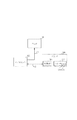
本形態においても、ビデオカメラの構成は図1に示した構成と同様である。また、ビデオカメラ100を用いたプリントシステムは図5に示す構成となる。
【0043】
図5のプリントシステムは図2のシステムとほぼ同様であるが、プリンタ200に対し、決定キー204を追加している点が異なる。
【0044】
第1の実施形態では、ダイレクトプリントキーの操作に応じて指定された位置より所定期間前の画面からスロー再生を行ったが、この様に再生された動画像を確認しながら所望の画面を選択するためには、かなり遅い速度で再生しなければならず、数秒前の画面から再生を開始したとしてもかなりの時間がかかってしまうことも考えられる。
【0045】
そこで、本形態では、指定された位置より所定期間前の画面からスロー再生を開始する構成は同様であるが、この所定期間前の画面からのスロー再生を繰り返し行うと共に、再生速度を段階的に遅くしつつ、戻る期間を段階的に短くする構成とした。
【0046】
本形態では、図1のROM111には図6に示すテーブルが記憶されている。
【0047】
図6において、601はダイレクトプリントキー203により指定された位置より前の画面に戻った後、スロー再生を行う際の再生速度を示しており、602は指定された位置より戻るべき期間(フレーム数)を示している。再生速度Sは、S1が最も速く、S2、S3の順に徐々に遅くなり、Smaxが最も遅い速度となる。また、再生範囲Fは、F1の値が最も大きい。つまり、指定された画面から戻る期間が最も長く、F2、F3の順に徐々に短くなり、Fmaxが最も短い。
【0048】
次に、図5のシステムによるダイレクトプリント処理について説明する。
【0049】
ダイレクトプリントを行う場合、ユーザはまず、図1の操作部114を操作して、ディスクDからの動画像信号の再生を指示する。制御部113はこの再生指示に従ってディスクI/F108を制御し、ディスクDに記録されている動画像信号を再生する。符号化処理部103は制御部113からの再生開始の指示に応じて、ディスクI/F108により再生された動画像信号を復号し、テレビ信号処理部115を介してモニタMに出力する。
【0050】
ユーザはこの状態でモニタMに表示されている再生画像を見ながら、所望の画面の再生タイミングにおいてプリンタ200のダイレクトプリントキー203を操作する。ダイレクトプリントキー203が操作されると、デジタルI/F201からダイレクトプリント要求を示すコマンドをビデオカメラ100のデジタルI/F109に対して出力する。
【0051】
ダイレクトプリントキー203によるダイレクトプリント要求に応じた制御部115の制御動作を図7のフローチャートを用いて説明する。
【0052】
ダイレクトプリント要求を受けると、まず、内部の変数iを0にリセットし(ステップS701)、図6に示したテーブルより、ダイレクトプリント要求のあった画面より戻るべきフレーム数Fi、ここではF0とその位置よりスロー再生を行う際の再生速度Si、ここではS0の値を検出してROM111より読み出す(ステップS702)。
【0053】
そして、ダイレクトプリント要求のあった画面からフレーム数Fiだけ前の画面より再生速度Siで再生を開始するようディスクI/F108を制御する(ステップS703)。スロー再生を開始した後、プリンタ200のダイレクトプリントキー203の操作があると、プリンタ200より再検索要求が出力され、ここでこの再検索要求があったか否かを検出する(ステップS704)。
【0054】
再検索要求がない場合、プリンタ204の操作による決定要求があったか否かを判別する(ステップS705)。ここで、フレーム決定要求があった場合、このフレーム決定要求の時点での再生画面を静止画像信号としてデジタルI/F107よりプリンタ200に送る。
【0055】
また、ステップS704で、スロー再生中に再検索要求があった場合、iを1だけ増加する(ステップS707)。そして、iの値が図6のテーブルの最大値maxを超えたか否かを検出し、超えていない場合、ステップS702に戻り、図6のテーブルで現在のSi、Fiの次の値を読み出してスロー再生を繰り返す(ステップS708)。また、iの値がmaxを超えていた場合、図6のテーブルで一番下に記載された再生速度Smax、再生範囲Fmaxとなるまで繰り返し再生してしまったと判断し、ステップS701に戻ってiを0にリセットする。
【0056】
また、ステップS705でスロー再生中にフレーム決定コマンドが入力されない場合、再生画像がダイレクトプリント要求を受けた画面となり、検索範囲の最後まで再生してしまったか否かを判別し、検索範囲が終了していない場合にはステップS704に戻る(ステップS709)。また、検索範囲が終了した場合、ステップS702に戻り、現在と同じSi、Fiにて処理を繰り返す。
【0057】
プリンタ200は、この様にダイレクトプリントキー203の操作後、決定キー204の操作に応じてビデオカメラ100から送信された画像信号に基づき、プリント処理を行う。
【0058】
この様に、本形態によれば、ダイレクトプリント要求があった場合、このダイレクトプリント要求があった時点での再生画面から所定期間前の画面まで戻り、スロー再生を行う場合に、スロー再生中におけるダイレクトプリントキーの操作に応じて、徐々に再生速度を遅くして繰り返しスロー再生を行うので、再生速度がユーザにより再生画面を認識可能な速度となった時点で所望の画面を決定することができ、短い時間で確実に所望の画面を選択することが可能となる。
【0059】
また、繰り返しスロー再生を行う際に、ダイレクトプリント要求のあった時点から戻る期間を徐々に短くしているので、短い時間で所望の画面を選択することが可能となる。
【0060】
なお、本形態では、図7のフローに示す様に、決定キーの操作があるまでスロー再生を繰り返すことになるが、例えば、ステップS708においてiの値がmaxを超えてしまった場合には自動的に処理を終了することも可能であり、また、所定の回数だけiの値がmaxになるまでの処理を繰り返した時点で処理を終了してもよい。また、同じ再生速度で所定回数繰り返した場合には処理を終了する構成でもよい。
【0061】
また、第1、第2の実施形態では、プリンタ200からのダイレクトプリント要求、フレーム決定要求に応じて処理を行ったが、ビデオカメラ100においてこの様なダイレクトプリント要求操作、フレーム決定操作を行う構成でもよい。
【0062】
次に、第3の実施形態について説明する。
【0063】
図8は本発明が適用されるビデオカメラ800の構成を示す図である。
【0064】
図8において、801は撮像部、802はマイクユニットであり、それぞれ動画像信号と音声信号を出力する。803は符号化処理部であり、撮影モードでは撮像部801からの動画像信号とマイク802からの音声信号とを符号化し、再生モードでは再生された画像信号と音声信号を復号する。本形態では、符号化処理部803は民生用デジタルVTRのフォーマットである、DVフォーマットに従って符号化、復号化処理を行う。804は表示制御部であり、表示パネル805に対して画像信号を出力する。805は表示パネルであり、本形態では液晶表示デバイスを用いる。
【0065】
806はデータバス、807はRAMであり、符号化処理部803による符号化、復号化処理などにおいて用いられる。808は記録再生部であり、符号化された画像、音声信号を回転ヘッドを用いて磁気テープTに対して記録再生する。809は外部I/Fであり、本形態では接続された機器に対して画像データのほか、各種のデジタルデータを送受信する。本形態では、IEEE1394フォーマットにてデータの送受信を行い、後述の様に、ケーブルを介してビデオプリンタと接続する。
【0066】
810は制御バス、811はROM、812はRAMである。ROM811は制御部813内のマイクロコンピュータにて用いる制御プログラムなど、各種のデータを記憶している。812は制御部113の処理に用いられる。813は制御部であり、操作部814からの指示に従ってビデオカメラ800の各部の動作を制御する。814は操作部であり、動画撮影の開始、停止トリガ、再生や早送り、巻き戻しキー、撮影モードと再生モードとを切り替えるためのモードスイッチ、更に、後述の様にテープTから再生された動画像から、所望の画面を選択して静止画像としてメモリカードMに記憶するための決定キーなど、各種のスイッチを有する。815はテレビ信号処理部であり、外部のテレビモニタなどの外部機器に対して符号化処理部から出力される画像、音声信号を出力すると共に、外部のビデオカメラなどから画像、音声信号を入力する。
【0067】
816はメモリカードI/Fであり、メモリカードMに対し、静止画像信号を記録再生する。本形態では、メモリカードI/F816はJPEG規格で静止画像信号を符号化、復号化する機能を持つ。
【0068】
この様なビデオカメラ800において、まず、動画撮影及び動画再生処理について説明する。
【0069】
操作部814のモードスイッチにより撮影モードが選択され、動画記録開始の指示があると、符号化処理部803は撮像部801からの動画像信号とマイク802からの音声信号を夫々符号化し、バス806を介して記録再生部808に出力する。記録再生部808は符号化された動画像信号と音声信号を記録に適した形態に変換し、磁気テープTに記録する。
【0070】
また、操作部814のモードスイッチにより再生モードが選択され、再生開始の指示があると、制御部813は記録再生部808を制御してテープTから動画像信号と音声信号とを再生する。符号化処理部803は再生された動画像信号と音声信号を復号し、復号した動画像信号を表示制御部804に出力し、動画像信号と音声信号をテレビ信号処理部815より出力する。表示制御部804は再生された動画像を表示パネル805に表示する。
【0071】
次に、メモリカードMに対する静止画撮影、及び静止画再生の処理について説明する。
【0072】
操作部814のモードスイッチによりメモリカードMへの静止画撮影モードが設定されると、符号化処理部803は撮像部801からの動画像信号を表示制御部804に出力し、表示制御部804は撮像部801からの動画像を表示パネル805に表示する。その後、静止画撮影のトリガ操作があると、制御部813はその時点で符号化処理部803に入力されていた一画面の画像信号をRAM807に記憶する。そして、メモリカードI/F816を制御し、このRAM807に記憶された一画面の画像信号をJPEGに従い符号化してメモリカードMに記録する。
【0073】
また、モードスイッチによりメモリカードMからの再生モードが設定されると、制御部813はメモリカードI/F816を制御して、メモリカードMに記録されている静止画像信号のうちの一つを選択して再生し、復号した後RAM807に書き込む。そして、制御部813は符号化処理部803を制御してRAM087に記録された静止画像信号を読み出し、表示制御部804に出力する。表示制御部804はこの静止画像を表示パネル805に表示する。
【0074】
次に、テープTに記録されている動画像信号のうちの一画面を静止画像信号としてメモリカードMに記録する場合の動作について説明する。
【0075】
本形態のビデオカメラ800は、テープTに記録されている動画像のうちの一画面を静止画像としてメモリカードMに記録する機能を持つ。
【0076】
この場合、まず、ユーザは操作部814により動画再生モードを設定し、動画像の再生を指示する。動画再生の指示により、前述の様にテープTから動画像信号が再生され、再生された動画像が表示パネル805に表示される。
【0077】
この様な状態で、ユーザは、表示パネル805に表示された再生動画像を確認しながら、所望の画面が再生された時点で操作部814のトリガキーを操作する。このトリガキーは動画撮影モードにおいて動画記録開始、及び停止の指示のために用いるキーと同じである。
【0078】
制御部813は動画像信号の再生中にトリガキーの操作入力を受けると、現在の動画像信号の再生位置をRAM812に格納すると共に、現在の再生位置から所定期間(フレーム数)、例えば本形態では10秒程度前の位置より、通常再生速度よりも遅い速度にて動画像信号を再生するよう記録再生部808を制御する。
【0079】
記録再生部808は制御部813からの制御信号に応じて、現在の再生位置から所定期間前の位置までテープTを巻き戻し、通常再生速度よりも遅い速度にて動画像信号を再生する。符号化処理部803はこの様に低速で再生された動画像信号を復号し、表示制御部804に出力する。表示制御部804は復号された動画像を表示パネル805に表示する。この結果、表示パネル805には、ユーザがトリガキーを操作した時点から所定期間前の画面より、スロー再生された動画像信号が表示される。
【0080】
この様にスロー再生された動画像を確認しながら、ユーザが再びトリガキーを操作すると、制御部813は記録再生部808を制御して再生動作を一時停止し、この時点で再生されている一画面の画像信号をRAM807に記憶する。そして、制御部813はメモリカードI/F816を制御し、RAM807に記憶された一画面の画像信号を符号化して静止画像信号としてメモリカードMに記憶する。
【0081】
そして、トリガキーが操作されてからメモリカードMに対して静止画の記憶が終了までの間、制御部113は、RAM807に記憶された画面を一時停止の画面として表示するよう、表示制御部804と符号化処理部803を制御する。
【0082】
メモリカードMに対する静止画像信号の記憶が終了すると、制御部813は記録再生部808を制御して、再び動画像の再生を開始する。
【0083】
また、スロー再生期間中にトリガキーが操作されずに、最初にトリガキーで指定した位置まで再生し終えた場合、制御部813は再びスロー再生を繰り返すよう記録再生部808を制御する。
【0084】
この様に、本形態では、テープに記録された動画像信号の中から所望の画面を静止画像としてメモリカードに記録する際、動画像信号の再生中にトリガキーを操作すると自動的に所定期間前の画面よりスロー再生を開始するので、ユーザは簡単な操作にて動画像の中から所望の画面を選択してメモリカードに記録することができる。
【0085】
なお、本形態では、動画再生中のトリガキー操作によって巻き戻し、スロー再生開始、及び画面の選択を指示したが、トリガキーをスチルカメラにて一般に用いられている二段スイッチの構成とし、動画再生中にトリガキーを半押しすることで巻き戻し、スロー再生に移行し、スロー再生中にトリガキーを全押しすることで画面を選択する構成としてもよい。
【0086】
また、スロー再生中にトリガキーが操作されず、所望の画面が選択されないまま最初にトリガキーで指定した画面まで再生し終えた場合、スロー再生を繰り返していたが、所定回数この処理を繰り返した場合、自動的に再生を停止するよう構成してもよい。
【0087】
また、前述の第1、第2の実施形態では、ビデオカメラにて再生された動画像から所望の画面を選択してプリントするシステム、第3の実施形態ではテープに記録された動画像から所望の画面を選択してメモリカードに記録する処理について本発明を適用した場合について説明したが、これ以外にも、動画像の中から所望の画面を選択する機能を実現する場合にも同様に本発明を適用可能となる。
【0088】
【発明の効果】
以上説明した様に、本発明によれば、動画像の再生中に指示された位置より所定期間前から自動的にスロー再生を行うことができ、指示された位置の直前の動画像の様子を詳細に確認することが可能となる。
【図面の簡単な説明】
【図1】本発明が適用されるビデオカメラの構成を示す図である。
【図2】本発明が適用されるプリントシステムの構成を示す図である。
【図3】本発明の実施形態により再生される画像の様子を示す図である。
【図4】本発明のプリントシステムの動作制御の様子を示す図である。
【図5】本発明が適用されるプリントシステムの他の構成を示す図である。
【図6】再生速度と再生開始位置とを示すテーブルを示す図である。
【図7】本発明の実施形態の動作を示すフローチャートである。
【図8】本発明が適用されるビデオカメラの他の構成を示す図である。[0001]
TECHNICAL FIELD OF THE INVENTION
The present invention relates to a playback apparatus, and more particularly, to control of a moving image playback operation.
[0002]
[Prior art]
2. Description of the Related Art Conventionally, a video printer that selects and prints one screen from a moving image reproduced by a VTR or the like is known.
[0003]
When printing is performed using such a video printer, the user operates the VTR to reproduce a moving image, and confirms the reproduced moving image and reproduces the moving image when a desired screen is reproduced. It pauses and sends a still image signal to the printer via a cable or the like to print.
[0004]
A video printer system of this type is disclosed in Japanese Patent Application Laid-Open No. 6-245179.
[0005]
[Patent Document 1]
JP-A-6-245179
[0006]
[Problems to be solved by the invention]
However, as described above, it is difficult to pause on a desired screen while checking a moving image, and usually, operations such as rewinding, fast-forwarding, playing, and pausing are repeated to search for a desired screen. Must choose.
[0007]
Such an operation is a very difficult operation for a user unfamiliar with the machine operation, and it takes a very long time to select a desired screen.
[0008]
An object of the present invention is to solve such a problem.
[0009]
Another object of the present invention is to make it possible to easily select a desired screen by a simple operation while reproducing a moving image.
[0010]
[Means for Solving the Problems]
In order to solve the above-described problems, in the present invention, a reproducing unit for reproducing a moving image signal from a recording medium, an instruction unit, and the instruction unit according to the instruction by the instruction unit during reproduction of the moving image signal. And control means for controlling the reproducing means so as to reproduce the moving image signal at a speed lower than the normal reproduction speed than the second screen before a predetermined period of the first screen corresponding to the first screen.
[0011]
BEST MODE FOR CARRYING OUT THE INVENTION
Hereinafter, embodiments of the present invention will be described.
[0012]
In the present embodiment, a case will be described in which the present invention is applied to a system for printing a desired screen by connecting a video camera and a video printer with a cable or the like.
[0013]
FIG. 1 is a diagram showing a configuration of a
[0014]
In FIG. 1,
[0015]
[0016]
109 is a control bus, 110 is a ROM, and 111 is a RAM. The
[0017]
Next, a printing system using the
[0018]
FIG. 2 is a diagram showing a configuration of a printing system to which the present invention is applied. In FIG. 2, the television
[0019]
Then, the moving image signal reproduced from the disk D is output to the monitor M for display, and one screen in the reproduced moving image signal is output to the
[0020]
The
[0021]
Next, the operation of the direct print function for selecting and printing a desired screen in a moving image signal reproduced from the disk D in the system of FIG. 2 will be described.
[0022]
When performing direct printing, the user first operates the
[0023]
In this state, the user operates the
[0024]
Upon receiving the direct print request, the digital I /
[0025]
In the present embodiment, a time code added to the reproduced moving image signal is detected, and this time code is used as reproduction position information.
[0026]
In response to a control signal from the
[0027]
When the user operates the
[0028]
The digital I /
[0029]
The
[0030]
In this embodiment, the moving image signal is encoded and recorded according to the MPEG system. In the MPEG system, an image signal is encoded by combining intra-frame encoding processing and inter-frame encoding processing. The inter-frame encoding processing encodes difference data between the image signal of the reference frame and its own frame. Therefore, it cannot be decrypted by itself. Therefore, in this embodiment, when the screen designated as a print candidate is an inter-frame coded screen, the image signal of the intra-frame coded screen closest to this screen is selected as a print candidate image signal. Is playing.
[0031]
The
[0032]
The above situation will be described with reference to FIG.
[0033]
FIG. 3 is a diagram showing a state of an image reproduced in the direct print processing.
[0034]
[0035]
Then, as indicated by
[0036]
Here, when the
[0037]
FIG. 42 shows the operation timing of the
[0038]
When the
[0039]
As described above, according to the present embodiment, when a direct print request is received during the playback of a moving image, the video camera automatically performs slow playback from the screen a predetermined period before the time of the request, so that the user can perform complicated operations. It is possible to select a desired screen from a moving image without performing the above operation.
[0040]
Further, in this case, a desired screen can be selected only by a very simple operation such as operation of the direct print key, so that even a user who is not operated by the video camera can easily utilize the direct print function.
[0041]
Next, a second embodiment of the present invention will be described.
[0042]
Also in this embodiment, the configuration of the video camera is the same as the configuration shown in FIG. A print system using the
[0043]
The printing system of FIG. 5 is almost the same as the system of FIG. 2, except that an
[0044]
In the first embodiment, slow playback is performed from a screen that is a predetermined period before the position designated according to the operation of the direct print key, but a desired screen is selected while confirming the reproduced moving image. In order to do so, playback must be performed at a very slow speed, and even if playback is started from a screen several seconds before, it may take a considerable amount of time.
[0045]
Thus, in the present embodiment, the slow reproduction is started from the screen before a predetermined period from the designated position in the same manner, but the slow reproduction from the screen before the predetermined period is repeatedly performed, and the reproduction speed is gradually increased. The structure is such that the return period is gradually shortened while being delayed.
[0046]
In this embodiment, the table shown in FIG. 6 is stored in the ROM 111 of FIG.
[0047]
In FIG. 6,
[0048]
Next, the direct print processing by the system of FIG. 5 will be described.
[0049]
When performing direct printing, the user first operates the
[0050]
In this state, the user operates the
[0051]
The control operation of the control unit 115 in response to a direct print request by the
[0052]
Upon receiving the direct print request, first, the internal variable i is reset to 0 (step S701), and from the table shown in FIG. 6, the number Fi of frames to be returned from the screen where the direct print request was made, here F0 and its The reproduction speed Si for performing slow reproduction from the position, here, the value of S0 is detected and read from the ROM 111 (step S702).
[0053]
Then, the disk I /
[0054]
If there is no re-search request, it is determined whether or not there is a determination request by operating the printer 204 (step S705). Here, when there is a frame determination request, the reproduction screen at the time of the frame determination request is sent to the
[0055]
If there is a re-search request during slow playback in step S704, i is increased by 1 (step S707). Then, it is detected whether or not the value of i exceeds the maximum value max in the table of FIG. 6, and if not, the process returns to step S702 to read the next value of the current Si and Fi in the table of FIG. The slow reproduction is repeated (step S708). If the value of i exceeds max, it is determined that the reproduction has been repeatedly performed until the reproduction speed Smax and the reproduction range Fmax described at the bottom of the table in FIG. 6 are reached, and the process returns to step S701 and returns to i. Is reset to 0.
[0056]
If the frame determination command is not input during the slow playback in step S705, the playback image becomes a screen for which a direct print request has been received, and it is determined whether or not playback has been completed to the end of the search range, and the search range ends. If not, the process returns to step S704 (step S709). When the search range ends, the process returns to step S702, and the process is repeated with the same Si and Fi as the current one.
[0057]
After operating the
[0058]
As described above, according to the present embodiment, when there is a direct print request, the display returns from the playback screen at the time of the direct print request to the screen before a predetermined period, and performs slow playback. In response to the operation of the direct print key, the playback speed is gradually reduced and the slow playback is repeatedly performed, so that the desired screen can be determined when the playback speed reaches a speed at which the user can recognize the playback screen. Thus, it is possible to reliably select a desired screen in a short time.
[0059]
In addition, when performing slow playback repeatedly, the period for returning from the time of the direct print request is gradually shortened, so that a desired screen can be selected in a short time.
[0060]
In this embodiment, as shown in the flow of FIG. 7, the slow playback is repeated until the enter key is operated. For example, if the value of i exceeds max in step S708, the automatic playback is performed. It is also possible to end the processing in a targeted manner, or the processing may be ended when the processing until the value of i becomes max a predetermined number of times is repeated. Further, the processing may be terminated when the processing is repeated a predetermined number of times at the same reproduction speed.
[0061]
In the first and second embodiments, processing is performed in response to a direct print request and a frame determination request from the
[0062]
Next, a third embodiment will be described.
[0063]
FIG. 8 is a diagram showing a configuration of a
[0064]
In FIG. 8,
[0065]
Reference numeral 806 denotes a data bus, and 807 denotes a RAM, which are used in encoding and decoding processing by the
[0066]
810 is a control bus, 811 is a ROM, and 812 is a RAM. The
[0067]
A memory card I / F 816 records and reproduces a still image signal on the memory card M. In this embodiment, the memory card I / F 816 has a function of encoding and decoding a still image signal according to the JPEG standard.
[0068]
In such a
[0069]
When a shooting mode is selected by a mode switch of the operation unit 814 and an instruction to start moving image recording is given, the
[0070]
When a reproduction mode is selected by a mode switch of the operation unit 814 and an instruction to start reproduction is issued, the
[0071]
Next, still image shooting and still image reproduction processing for the memory card M will be described.
[0072]
When the still image shooting mode for the memory card M is set by the mode switch of the operation unit 814, the
[0073]
When the playback mode from the memory card M is set by the mode switch, the
[0074]
Next, an operation in the case where one screen of the moving image signals recorded on the tape T is recorded on the memory card M as a still image signal will be described.
[0075]
The
[0076]
In this case, first, the user sets the moving image reproduction mode using the operation unit 814 and instructs reproduction of a moving image. In response to an instruction to reproduce a moving image, a moving image signal is reproduced from the tape T as described above, and the reproduced moving image is displayed on the
[0077]
In such a state, the user operates the trigger key of the operation unit 814 when a desired screen is reproduced, while checking the reproduced moving image displayed on the
[0078]
When the
[0079]
The recording / reproducing
[0080]
When the user operates the trigger key again while checking the slow-moving moving image, the
[0081]
Then, during a period from the operation of the trigger key to the end of storage of the still image in the memory card M, the
[0082]
When the storage of the still image signal in the memory card M ends, the
[0083]
When the trigger key is not operated during the slow playback period and the playback is first completed to the position specified by the trigger key, the
[0084]
As described above, in the present embodiment, when a desired screen is recorded as a still image from a moving image signal recorded on a tape as a still image, when a trigger key is operated during reproduction of the moving image signal, a predetermined period is automatically obtained. Since the slow reproduction is started from the screen, the user can select a desired screen from the moving images and record it on the memory card by a simple operation.
[0085]
In the present embodiment, the rewind, the slow playback start, and the screen selection are instructed by the trigger key operation during the moving image playback. Alternatively, the screen may be selected by pressing the trigger key halfway, rewinding, shifting to slow playback, and pressing the trigger key fully during slow playback.
[0086]
Also, if the trigger key is not operated during slow playback and the desired screen is not selected and the playback is first completed to the screen specified by the trigger key, the slow playback is repeated. You may be comprised so that reproduction | regeneration may be stopped automatically.
[0087]
In the first and second embodiments described above, a system for selecting and printing a desired screen from a moving image reproduced by a video camera is used. In the third embodiment, a desired image is selected from a moving image recorded on a tape. The case where the present invention is applied to the process of selecting a screen and recording it on a memory card has been described. However, the present invention is also applicable to a case where a function of selecting a desired screen from a moving image is realized. The invention can be applied.
[0088]
【The invention's effect】
As described above, according to the present invention, slow playback can be automatically performed from a position instructed during reproduction of a moving image for a predetermined period before, and the state of the moving image immediately before the instructed position can be displayed. It is possible to check in detail.
[Brief description of the drawings]
FIG. 1 is a diagram showing a configuration of a video camera to which the present invention is applied.
FIG. 2 is a diagram illustrating a configuration of a print system to which the present invention is applied.
FIG. 3 is a diagram showing a state of an image reproduced according to the embodiment of the present invention.
FIG. 4 is a diagram showing a state of operation control of the print system of the present invention.
FIG. 5 is a diagram illustrating another configuration of a print system to which the present invention is applied.
FIG. 6 is a diagram showing a table indicating a reproduction speed and a reproduction start position.
FIG. 7 is a flowchart showing the operation of the embodiment of the present invention.
FIG. 8 is a diagram showing another configuration of a video camera to which the present invention is applied.
Claims (24)
指示手段と、
前記動画像信号の再生中の前記指示手段による指示に応じて、前記指示に対応した第1の画面の所定期間前の第2の画面より通常再生速度よりも遅い速度で前記動画像信号を再生するよう前記再生手段を制御する制御手段とを備える再生装置。Reproducing means for reproducing a moving image signal from a recording medium;
Indicating means;
In response to an instruction from the instruction means during reproduction of the moving image signal, the moving image signal is reproduced at a speed lower than a normal reproduction speed than a second screen before a predetermined period of the first screen corresponding to the instruction. And a control means for controlling the reproduction means to perform the reproduction.
前記制御手段は、前記遅い速度での動画像信号の再生中に前記指定手段により指定された画面の画像信号を静止画像信号として抽出することを特徴とする請求項1記載の再生装置。A designating means for designating a desired screen from the moving image signal,
2. The reproducing apparatus according to claim 1, wherein the control unit extracts the image signal of the screen specified by the specifying unit as a still image signal during reproduction of the moving image signal at the low speed.
前記再生装置は、前記動画像信号の再生中における第1の指示に応じて、この第1の指示に対応した画面の所定期間前の画面から通常再生速度よりも遅い速度にて前記動画像信号を再生すると共に、前記遅い速度での動画像信号の再生中における第2の指示に応じて動画像信号中の一画面の画像信号を選択し、前記静止画像信号として前記印刷装置に送信することを特徴とする画像処理システム。A system in which one screen in a moving image signal reproduced by a reproduction apparatus is transmitted to a printing apparatus as a still image signal, and the printing apparatus prints a still image indicated by the one-screen still image signal,
In response to a first instruction during the reproduction of the moving image signal, the reproducing device starts the moving image signal at a speed lower than a normal reproducing speed from a screen that is a predetermined period before a screen corresponding to the first instruction. And selecting an image signal of one screen in the moving image signal according to a second instruction during the reproduction of the moving image signal at the slow speed, and transmitting the selected image signal as the still image signal to the printing apparatus. An image processing system characterized by the following.
前記動画像信号の再生中における第1の指示に応じて、この第1の指示に対応した画面の所定期間前の画面から通常再生速度よりも遅い速度にて前記動画像信号を再生すると共に、前記遅い速度での動画像信号の再生中における第2の指示に応じて動画像信号中の一画面の画像信号を選択し、前記静止画像信号として前記記憶デバイスに記憶することを特徴とする画像処理装置。An apparatus that extracts one screen in a moving image signal reproduced from a recording medium as a still image signal and stores the extracted still image signal in a storage device,
In response to a first instruction during reproduction of the moving image signal, the moving image signal is reproduced at a speed lower than a normal reproduction speed from a screen that is a predetermined period before a screen corresponding to the first instruction, An image characterized by selecting an image signal of one screen in a moving image signal according to a second instruction during reproduction of the moving image signal at the slow speed, and storing the selected image signal in the storage device as the still image signal. Processing equipment.
前記動画像信号の再生中の指示手段による指示に応じて、前記指示に対応した第1の画面の所定期間前の第2の画面より通常再生速度よりも遅い速度で前記動画像信号を再生するよう前記再生ステップを制御する制御ステップとを有する再生方法。A reproducing step of reproducing a moving image signal from a recording medium;
The moving image signal is reproduced at a speed lower than a normal reproduction speed from a second screen before a predetermined period of the first screen corresponding to the instruction in response to an instruction from the instruction means during reproduction of the moving image signal. And a control step of controlling the reproduction step.
前記動画像信号の再生中における第1の指示に応じて、この第1の指示に対応した画面の所定期間前の画面から通常再生速度よりも遅い速度にて前記動画像信号を再生すると共に、前記遅い速度での動画像信号の再生中における第2の指示に応じて動画像信号中の一画面の画像信号を選択し、前記静止画像信号として前記記憶デバイスに記憶することを特徴とする画像処理方法。A method of extracting one screen in a moving image signal reproduced from a recording medium as a still image signal and storing the same in a storage device,
In response to a first instruction during reproduction of the moving image signal, the moving image signal is reproduced at a speed lower than a normal reproduction speed from a screen that is a predetermined period before a screen corresponding to the first instruction, An image characterized by selecting an image signal of one screen in a moving image signal according to a second instruction during reproduction of the moving image signal at the slow speed, and storing the selected image signal in the storage device as the still image signal. Processing method.
Priority Applications (1)
| Application Number | Priority Date | Filing Date | Title |
|---|---|---|---|
| JP2003005851A JP2004220679A (en) | 2003-01-14 | 2003-01-14 | Reproducing device |
Applications Claiming Priority (1)
| Application Number | Priority Date | Filing Date | Title |
|---|---|---|---|
| JP2003005851A JP2004220679A (en) | 2003-01-14 | 2003-01-14 | Reproducing device |
Publications (2)
| Publication Number | Publication Date |
|---|---|
| JP2004220679A true JP2004220679A (en) | 2004-08-05 |
| JP2004220679A5 JP2004220679A5 (en) | 2006-03-02 |
Family
ID=32896405
Family Applications (1)
| Application Number | Title | Priority Date | Filing Date |
|---|---|---|---|
| JP2003005851A Pending JP2004220679A (en) | 2003-01-14 | 2003-01-14 | Reproducing device |
Country Status (1)
| Country | Link |
|---|---|
| JP (1) | JP2004220679A (en) |
Cited By (6)
| Publication number | Priority date | Publication date | Assignee | Title |
|---|---|---|---|---|
| JP2008085689A (en) * | 2006-09-28 | 2008-04-10 | Casio Comput Co Ltd | Image pickup device, image pickup control program and image pickup control method |
| JP2008124896A (en) * | 2006-11-14 | 2008-05-29 | Casio Comput Co Ltd | Imaging apparatus and program therefor |
| EP2067350A1 (en) * | 2006-09-28 | 2009-06-10 | Casio Computer Co., Ltd. | Imaging apparatus and control method for capturing and recording a still image from a video |
| JP2009159094A (en) * | 2007-12-25 | 2009-07-16 | Canon Inc | Imaging apparatus |
| JP2009177507A (en) * | 2008-01-24 | 2009-08-06 | Canon Inc | Device and method for reproducing dynamic image, program and storage medium |
| US7948526B2 (en) | 2006-11-14 | 2011-05-24 | Casio Computer Co., Ltd. | Imaging apparatus, imaging method and program thereof |
-
2003
- 2003-01-14 JP JP2003005851A patent/JP2004220679A/en active Pending
Cited By (10)
| Publication number | Priority date | Publication date | Assignee | Title |
|---|---|---|---|---|
| JP2008085689A (en) * | 2006-09-28 | 2008-04-10 | Casio Comput Co Ltd | Image pickup device, image pickup control program and image pickup control method |
| EP2067350A1 (en) * | 2006-09-28 | 2009-06-10 | Casio Computer Co., Ltd. | Imaging apparatus and control method for capturing and recording a still image from a video |
| TWI394437B (en) * | 2006-09-28 | 2013-04-21 | Casio Computer Co Ltd | Imaging apparatus, recording medium for recording a computer program, and imaging control method |
| US8488043B2 (en) | 2006-09-28 | 2013-07-16 | Casio Computer Co., Ltd. | Imaging apparatus, recording medium for recording a computer program, and imaging control method |
| JP2008124896A (en) * | 2006-11-14 | 2008-05-29 | Casio Comput Co Ltd | Imaging apparatus and program therefor |
| JP4501927B2 (en) * | 2006-11-14 | 2010-07-14 | カシオ計算機株式会社 | Imaging apparatus and program thereof |
| US7948526B2 (en) | 2006-11-14 | 2011-05-24 | Casio Computer Co., Ltd. | Imaging apparatus, imaging method and program thereof |
| US8817133B2 (en) | 2006-11-14 | 2014-08-26 | Casio Computer Co., Ltd. | Imaging apparatus, imaging method and program thereof |
| JP2009159094A (en) * | 2007-12-25 | 2009-07-16 | Canon Inc | Imaging apparatus |
| JP2009177507A (en) * | 2008-01-24 | 2009-08-06 | Canon Inc | Device and method for reproducing dynamic image, program and storage medium |
Similar Documents
| Publication | Publication Date | Title |
|---|---|---|
| JP3246602B2 (en) | Information processing apparatus, information processing method, and program storage medium | |
| JP2001111963A (en) | Recording and reproducing method for video camera utilizing optical disk | |
| US8577161B2 (en) | Reproduction apparatus | |
| JP4621571B2 (en) | Playback device | |
| JPWO2009072276A1 (en) | Image encoding apparatus, video camera, integrated circuit, and image encoding method | |
| JP2006261953A (en) | Recording and reproducing device, its controlling method, and imaging apparatus | |
| JP5284074B2 (en) | Image processing apparatus and image processing method | |
| JP2004220679A (en) | Reproducing device | |
| JP2006279262A (en) | Coded video conversion apparatus, conversion method and program therefor | |
| JP3591443B2 (en) | Program signal recording and playback device | |
| KR100883119B1 (en) | Method for editing of moving picture file list | |
| US9025931B2 (en) | Recording apparatus, recording method, and program | |
| JP2010283689A (en) | Imaging and recording apparatus, control method thereof, and program | |
| JP4272753B2 (en) | REPRODUCTION DEVICE, ITS CONTROL METHOD, AND COMPUTER-READABLE STORAGE MEDIUM | |
| JP6112852B2 (en) | Recording apparatus, recording method, and program | |
| JP5685075B2 (en) | Recording apparatus, recording method, and program | |
| JP4498207B2 (en) | Video processing apparatus and video processing method | |
| JP2007006025A (en) | Apparatus and method for reproducing video | |
| KR20070003843A (en) | Video signal playback unit and video signal playback method | |
| JP3867737B2 (en) | Data processing apparatus and method | |
| JP4033839B2 (en) | Image recording / reproducing apparatus and image recording / reproducing method | |
| JP2013005054A (en) | Reproduction device and reproduction method | |
| JP2004201341A (en) | Recording and reproducing apparatus | |
| JP5597978B2 (en) | Dubbing equipment | |
| JP2008099081A (en) | Recording reproduction device |
Legal Events
| Date | Code | Title | Description |
|---|---|---|---|
| A521 | Written amendment |
Free format text: JAPANESE INTERMEDIATE CODE: A523 Effective date: 20060106 |
|
| A621 | Written request for application examination |
Free format text: JAPANESE INTERMEDIATE CODE: A621 Effective date: 20060106 |
|
| A977 | Report on retrieval |
Free format text: JAPANESE INTERMEDIATE CODE: A971007 Effective date: 20060825 |
|
| A131 | Notification of reasons for refusal |
Free format text: JAPANESE INTERMEDIATE CODE: A131 Effective date: 20060905 |
|
| A521 | Written amendment |
Free format text: JAPANESE INTERMEDIATE CODE: A523 Effective date: 20061027 |
|
| A02 | Decision of refusal |
Free format text: JAPANESE INTERMEDIATE CODE: A02 Effective date: 20061128 |