JP2004218427A - Opening/closing structure of folding door and self-traveling system of wheeled chair - Google Patents
Opening/closing structure of folding door and self-traveling system of wheeled chair Download PDFInfo
- Publication number
- JP2004218427A JP2004218427A JP2004090845A JP2004090845A JP2004218427A JP 2004218427 A JP2004218427 A JP 2004218427A JP 2004090845 A JP2004090845 A JP 2004090845A JP 2004090845 A JP2004090845 A JP 2004090845A JP 2004218427 A JP2004218427 A JP 2004218427A
- Authority
- JP
- Japan
- Prior art keywords
- folding door
- door
- traveling body
- folding
- opening
- Prior art date
- Legal status (The legal status is an assumption and is not a legal conclusion. Google has not performed a legal analysis and makes no representation as to the accuracy of the status listed.)
- Withdrawn
Links
Images


Abstract
Description
本発明は、折戸の開閉構造及び折戸を備えた建築構造物内における車椅子の自動走行システムに関するものである。 The present invention relates to an open / close structure for a folding door and an automatic traveling system for a wheelchair in a building structure including the folding door.
従来、折戸は、電話ボックス等に広く使用されているが、一般住宅用としてはユニットバス等の扉に使用される他はその使用範囲は限られていた。ところが、折戸は、開き戸に比べてその旋回範囲が小さいので、車椅子を利用する者にとって非常に便利なものである。
一般に折戸は、幅寸法を異にする鋼板などの金属製の小扉と大扉とを備え、小扉が扉枠の縦桟にヒンジを介して回動可能に取り付けられている。大扉は、小扉にヒンジを介して回動可能に連結されており、全体として大扉と小扉が折り畳み自在に連結されている。
Conventionally, folding doors have been widely used in telephone boxes and the like, but their use range is limited except that they are used for doors of unit baths and the like for ordinary houses. However, folding doors are very convenient for those who use wheelchairs because they have a smaller turning range than hinged doors.
In general, a folding door includes a small door made of metal such as a steel plate having a different width dimension and a large door, and the small door is rotatably attached to a vertical rail of a door frame via a hinge. The large door is rotatably connected to the small door via a hinge, and the large door and the small door are foldably connected as a whole.
一方、従来のように構成された折戸では、以下のような問題点を有していた。
先ず、折戸を自動開閉しようとすると、機構が複雑となると共に、非常に高価であった。
On the other hand, the conventional folding door has the following problems.
First, when trying to automatically open and close the folding door, the mechanism becomes complicated and very expensive.
この発明は、このような事情を考慮してなされたもので、その目的は、自動開閉を簡易に実現することができる折戸の開閉構造及び折戸を使用した車椅子の自動走行システムを提供することにある。 The present invention has been made in view of such circumstances, and an object of the present invention is to provide a folding door opening / closing structure capable of easily realizing automatic opening / closing and a wheelchair automatic traveling system using the folding door. is there.
上記の目的を達成するために、この発明は以下の手段を提供している。
請求項1に係る発明は、戸枠の一端にヒンジ結合された第1の折戸構成体と、上端が上桟内に敷設されたレール上を走行する走行体に吊下された複数の折戸構成体とを有する折戸であって、前記走行体を前進及び後退方向に駆動する駆動機構と前記走行体の下端に突出した旋回軸と、前記旋回軸の遊嵌されたカム溝を有するカム部材とから成る開閉機構を備え、前記カム部材は、前記走行体が前記第1の折戸構成体方向に移動する際に前記折戸構成体を開成する方向に案内するカム溝を有することを特徴とするものである。
In order to achieve the above object, the present invention provides the following means.
The invention according to
この発明に係る折戸の開閉構造においては、駆動機構により走行体を駆動することにより折戸構成体を開成することができる。 In the folding door opening and closing structure according to the present invention, the folding door structure can be opened by driving the traveling body by the drive mechanism.
請求項2に係る発明は、請求項1記載の折戸の開閉構造において、前記カム部材は前記走行体が前記第1の折戸構成体から離間する方向に移動する際に前記折戸構成体を閉成する方向に案内するカム溝を有することを特徴とするものである。 According to a second aspect of the present invention, in the folding door opening / closing structure according to the first aspect, the cam member closes the folding door structure when the traveling body moves in a direction away from the first folding door structure. It has a cam groove which guides in the direction to do.
この発明に係る折戸の開閉構造においては、駆動機構によって走行体を駆動することにより、折戸構成体を閉成することができる。 In the folding door opening and closing structure according to the present invention, the folding door structure can be closed by driving the traveling body by the drive mechanism.
請求項3に係る発明は、請求項1または2に記載の折戸の開閉構造において、戸枠の一端にヒンジ結合された第1の折戸構成体と、前記第1の折戸構成体とヒンジ結合されると共に上端が上桟内に敷設されたレール上を走行する走行体に吊下された第2の折戸構成体とを有する折戸であって、前記戸枠と第1の折戸構成体を連結するヒンジ軸の軸心と前記第2の折戸構成体を吊り下げ支持する旋回軸の軸心を結ぶ直線より、前記第1の折戸構成体と第2の折戸構成体を連結するヒンジ軸の軸心が折戸の突出方向に位置することを特徴とするものである。 According to a third aspect of the present invention, there is provided the folding door opening / closing structure according to the first or second aspect, wherein the first folding door structure is hinged to one end of the door frame and is hinged to the first folding door structure. And a second folding door structure suspended from a traveling body traveling on a rail whose upper end is laid in the upper rail, and connecting the door frame and the first folding door structure The axis of the hinge shaft that connects the first folding door component and the second folding door from a straight line that connects the axis of the hinge shaft and the axis of the pivot that supports the second folding door component in a suspended manner. Is located in the protruding direction of the folding door.
この発明に係る折戸においては、第1の折戸構成体と第2の折戸構成体を連結するヒンジ軸の軸心が、戸枠と第1の折戸構成体を連結するヒンジ軸の軸心と第2の折戸構成体を吊り下げ支持する旋回軸の軸心を結ぶ直線より折戸の突出方向に位置しているので、走行体を直線的に駆動するのみ、折戸構成体を開成することができる。 In the folding door according to the present invention, the axial center of the hinge shaft that connects the first folding door structure and the second folding door structure is the axis of the hinge shaft that connects the door frame and the first folding door structure. Since the folding door structure is located in the protruding direction of the folding door from the straight line connecting the axes of the pivots that suspend and support the folding door structure, the folding door structure can be opened only by driving the traveling body linearly.
請求項4に係る発明は、複数の部屋と各部屋を仕切る仕切部に設けられた1以上の請求項1〜3の何れかに記載の折戸を備えた建築構造物において、車椅子に搭載可能、または保持可能であり前記折戸の駆動機構を制御する指令制御装置と、前記車椅子を前記建築構造物内を移動案内する手段とを備えてなることを特徴とする。
The invention according to
この発明に係る車椅子の自動走行システムにおいては、車椅子に乗ったまま建築構造物内を自由に移動できると共に、各部屋の折戸を自由に開閉することができる。 In the automatic traveling system for a wheelchair according to the present invention, it is possible to freely move within the building structure while riding on the wheelchair, and to freely open and close the folding doors in each room.
請求項1に係る発明によれば、戸枠の一端にヒンジ結合された第1の折戸構成体と、上端が上桟内に敷設されたレール上を走行する走行体に吊下された複数の折戸構成体とを有する折戸であって、前記走行体を前進及び後退方向に駆動する駆動機構と前記走行体の下端に突出した旋回軸と、前記旋回軸の遊嵌されたカム溝を有するカム部材とから成る開閉機構を備え、前記カム部材は、前記走行体が前記第1の折戸構成体方向に移動する際に前記折戸構成体を開成する方向に案内する案内溝を有するので、走行体を駆動するのみで折戸を自動的に開成することができる。 According to the first aspect of the present invention, a first folding door structure that is hinged to one end of the door frame, and a plurality of suspensions that are suspended from a traveling body that travels on a rail that is laid in the upper rail. A folding door having a folding door structure, a cam having a drive mechanism for driving the traveling body in the forward and backward directions, a pivot shaft protruding from a lower end of the traveling body, and a cam groove in which the pivot shaft is loosely fitted. And the cam member has a guide groove that guides in a direction to open the folding door component when the traveling member moves in the direction of the first folding door component. The folding door can be opened automatically only by driving the.
また、請求項2に係る発明によれば、請求項1記載の折戸の開閉構造において、前記カム部材は前記走行体が前記第1の折戸構成体から離間する方向に移動する際に前記折戸構成体を閉成する方向に案内する案内溝を有するので、走行体を駆動するのみで折戸を自動的に閉成することができる。 According to a second aspect of the present invention, in the folding door opening / closing structure according to the first aspect, the cam member moves when the traveling body moves in a direction away from the first folding door structure. Since the guide groove for guiding the body in the closing direction is provided, the folding door can be automatically closed only by driving the traveling body.
また、請求項3に係る発明によれば、請求項1または2に記載の折戸の開閉構造において、前記戸枠の一端にヒンジ結合された第1の折戸構成体と、前記第1の折戸構成体とヒンジ結合されると共に上端が上桟内に敷設されたレール上を走行する走行体に吊下された第2の折戸構成体とを有する折戸であって、前記戸枠と第1の折戸構成体を連結するヒンジ軸の軸心と前記第2の折戸構成体を吊り下げ支持する旋回軸の軸心を結ぶ直線より、前記第1の折戸構成体と第2の折戸構成体を連結するヒンジ軸の軸心が折戸の突出方向に位置するので、走行体をレールに沿って駆動するのみで容易に第2の折戸構成体が旋回して、開成することができる。
Moreover, according to the invention which concerns on
また、請求項4に係る発明によれば、複数の部屋と各部屋を仕切る仕切部に設けられた1以上の請求項1〜3の何れかに記載の折戸を備えた建築構造物において、車椅子に搭載可能、または保持可能であり前記折戸の駆動機構を制御する指令制御装置と、前記車椅子を前記建築構造物内を移動案内するシステムとを備えたので、車椅子に乗ったまま指令制御装置によって折戸の開閉を行うことができる。
Moreover, according to the invention which concerns on
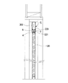
以下、図面を参照し、この発明に係る折戸の開閉構造の一実施の形態について説明する。図1は本発明に係る開閉構造を有する折戸を室内側から見た正面図、図2は本発明に係る折戸の背面図、図3は本発明に係る折戸の縦断面図である。 Hereinafter, an embodiment of a folding door opening and closing structure according to the present invention will be described with reference to the drawings. FIG. 1 is a front view of a folding door having an opening / closing structure according to the present invention as viewed from the indoor side, FIG. 2 is a rear view of the folding door according to the present invention, and FIG. 3 is a longitudinal sectional view of the folding door according to the present invention.
折戸100は、幅寸法を異にする鋼板等の金属製の小扉110と大扉(第1の折戸構成体)120とを備え、この実施の形態では、折戸構成体である小扉110と大扉120の幅寸法は概ね1:2に設定されている。
小扉110は戸枠200の縦桟210にヒンジ1を介して回動可能に取り付けられている。大扉120は、この小扉110において縦桟210とは反対側にヒンジ2を介して回動可能に連結されており、これにより小扉110と大扉120が折り畳み自在に連結されている。
The folding
The
また、大扉120は、その幅方向の中央に旋回軸3を有し、この旋回軸3は、戸枠200の上桟220に設けられたレール221を走行するローラー4を含む車台(走行体)5に連結されていて、大扉120はレール221に吊り下げ支持されると共に、旋回軸3を回転中心として回転自在に支持されている。
大扉120は、室外側表面に引き手6が設けられており、室内側表面に引き手7が設けられている。
The
The
また、この折戸100は、電気駆動による開閉機構Kを有している。動開閉機構Kは、戸枠200の上桟220内にリニアモータ(駆動機構)300が固定された構成を有しており、大扉120を吊り下げ支持している台車5を前記戸枠200の上桟220内に設けられたレール221に沿って駆動する。
The folding
また、図4、図5に示すように、大扉120の上端には、第1、第2の案内溝310,320を有するカム部材330が取り付けられている。第1、第2の案内溝310,320は、それぞれ台車5の移動方向に対して所定の角度を有して形成されている。大扉120を吊り下げ支持している旋回軸3は、この案内溝内に遊嵌されている。
As shown in FIGS. 4 and 5, a
図4は、大扉120とカム部材330と台車5との関係を示しており、図5はカム部材330の詳細を示している。カム部材330は、断面ほぼコ字状をしており、中央に第1の案内溝310と第2の案内溝320が所定の角度を有して形成されている。また、第1、第2の案内溝310、320の下には凹部350が形成されると共に、側面に旋回軸3挿入用の開口340が形成されており、旋回軸3を前記案内溝内に挿入後、この開口340を閉鎖部材351で閉じる。閉鎖部材351は、カム部材330の側面にビス10で固着される。
以上の様に構成すると、旋回軸3の先端に形成された円盤部3bが凹部350に遊嵌されて、旋回軸3が抜けることなく、大扉120を吊り下げることができる。また、第1の案内溝310と第2の案内溝320は、連通しているので、旋回軸3が自由に移動することができる。
FIG. 4 shows the relationship between the
If comprised as mentioned above, the
図6は、本発明の折戸の開閉状態を説明する平面図である。ここで、折戸は縦桟210の一端にヒンジ1で結合された小扉110と、この小扉110にヒンジ2で連結された大扉120とから構成される。また、大扉120には引き手7が取り付けられている。ヒンジ2は、所謂隠し蝶番と呼ばれるもので、折戸構成体を閉成した際に外部からヒンジ部が見えない。ヒンジ1は、小扉110の側面に配置されている。大扉120を吊り下げ支持する旋回軸3は、大扉120の略幅方向の中心に位置している。また、ヒンジ2の軸心は、小扉110或いは大扉120の幅方向の中心に位置している。したがって、ヒンジ1の軸心とヒンジ2の軸心と旋回軸3の軸心とは、三角形をなしている。このため、旋回軸3が台車5によって直線的に移動するのみで、大扉120が旋回軸3を中心に旋回して折戸が開成する。
FIG. 6 is a plan view illustrating the open / closed state of the folding door of the present invention. Here, the folding door includes a
図7は、本発明に係る折戸の開動作を示す説明図である。図7における(A)〜(D)は、図6における旋回軸3が(A)〜(D)の位置にある場合に対応している。この状態で大扉120と小扉110は、一直線状に配置されており、折戸は閉成されている。ここで台車5が図外の駆動機構によって矢印L方向に駆動されると、旋回軸3は、第1の案内溝310の第1面310aに沿って移動しようとする。この時、第1の案内溝310は、旋回軸3の移動方向と所定角度を有しており、移動することができない。更に、旋回軸3が駆動機構により駆動されると、(B)に示すように、大扉120が旋回軸3を中心に反時計方向に回動する。大扉120が回動すると、旋回軸3は第1の案内溝310の先端まで進み、その後は大扉120と共に矢印L方向に移動する。ヒンジ2は、大扉120の旋回動作によって、折れ曲がるきっかけができたので、その後、大扉120は矢印L方向に移動するのみで、折れ曲がる(図(C)参照)。(D)の位置では、大扉120と小扉110とは完全に折り重なり、折戸が開成される。
FIG. 7 is an explanatory view showing the opening operation of the folding door according to the present invention. (A)-(D) in FIG. 7 respond | corresponds when the turning axis |
図8は、本発明に係る折戸の閉動作を示す説明図である。図8における(A)〜(D)は、図6における旋回軸3が(A)〜(D)の位置にある場合に対応している。(D)の位置では、大扉120と小扉110とは完全に折り重なており、旋回軸3が矢印R方向に移動すると、大扉120は旋回軸3を中心に時計方向に回動しつつ矢印R方向へ移動する。旋回軸3が矢印R方向に移動すると、(C)、(D)に示すように大扉120は、旋回しつつ移動する。小扉110も大扉120に追随してヒンジ1を中心に回動する。更に、(D)の位置では、旋回軸3が第2の案内溝320に進入しようとする。この時、第2の案内溝320は、旋回軸3の進行方向に対して所定の角度を有しているので、大扉120が矢印X方向の旋回力を受けることとなる。この旋回力によって、小扉110と大扉120とを連結するヒンジ部が、完全に平坦状態となり、折戸が閉成される。
FIG. 8 is an explanatory view showing the folding operation of the folding door according to the present invention. (A) to (D) in FIG. 8 correspond to the case where the turning
次に、以上のように構成された本発明の折戸の開閉構造によれば、直線運動しかできない駆動機構(リニアモータ)によって折戸を確実に開閉することができる。
なお、上記の実施の形態においては、駆動機構としてリニアモータを使用したが、リニアモータに限られることなく、他の駆動機構を用いてもよい。
Next, according to the folding door opening / closing structure of the present invention configured as described above, the folding door can be reliably opened and closed by a drive mechanism (linear motor) capable of only linear motion.
In the above embodiment, the linear motor is used as the drive mechanism. However, the drive mechanism is not limited to the linear motor, and other drive mechanisms may be used.
図9は、本発明の車椅子の自動走行システムを示す説明図、図10は本発明の車椅子の自動走行システムに使用する車椅子を示す説明図である。図9に示す車椅子の自動走行システムにおいて、家屋内に車椅子の走行経路50として磁気テープが敷設されている。また、家屋内の各部屋を仕切る部位には、本発明の開閉構造を有した折戸100が配置されている。
FIG. 9 is an explanatory view showing an automatic traveling system for a wheelchair according to the present invention, and FIG. 10 is an explanatory view showing a wheelchair used for the automatic traveling system for a wheelchair according to the present invention. In the wheelchair automatic traveling system shown in FIG. 9, a magnetic tape is laid in the house as a traveling
図10に示す車椅子51は、前述した折戸の駆動機構300を制御する指令制御装置52が搭載されている。また、車椅子51のアームレスト部51aには、指令制御装置52を操作するための操作スイッチ53が配設されている。更に、指令制御装置52は、走行経路50として敷設された磁気テープの存在、不存在を検出して、車椅子51が正規の走行経路50に位置するか否かを知らせる。走行経路50、この走行経路50に敷設された磁気テープ等は、車椅子51を建築構造物内において移動案内する手段を構成している。
The
以上のように構成した車椅子の自動走行システムによれば、家屋内外の走行経路50に沿って車椅子51を安全に走行させることができる。また、走行経路50上に存在する折戸100は、車椅子51に搭載した指令制御装置52によって、遠隔操作により開閉することができる。
According to the wheelchair automatic travel system configured as described above, the
尚、本発明は以上の実施例に限ることなく本発明の技術思想に基づいて種々の設計変更が可能である。 The present invention is not limited to the above embodiments, and various design changes can be made based on the technical idea of the present invention.
3 旋回軸
5 台車(走行体)
100 折戸
110 小扉
120 大扉
200 戸枠
210 縦桟
220 上桟
221 レール
300 リニアモータ(駆動機構)
310 第1の案内溝
320 第2の案内溝
330 カム部材
K 開閉機構
3 Rotating
100
310
Claims (4)
前記走行体を前進及び後退方向に駆動する駆動機構と前記走行体の下端に突出した旋回軸と、前記旋回軸の遊嵌されたカム溝を有するカム部材とから成る開閉機構を備え、前記カム部材は、前記走行体が前記第1の折戸構成体方向に移動する際に前記折戸構成体を開成する方向に案内する案内溝を有することを特徴とする折戸の開閉構造。 A folding door having a first folding door structure hinged to one end of a door frame, and a folding door structure suspended from a traveling body whose upper end runs on a rail laid in an upper rail,
An opening / closing mechanism comprising: a drive mechanism that drives the traveling body in a forward and backward direction; a turning shaft that projects from a lower end of the traveling body; and a cam member that has a cam groove in which the turning shaft is loosely fitted. The member has a guide groove that guides in a direction to open the folding door component when the traveling body moves in the direction of the first folding door component.
前記カム部材は前記走行体が前記第1の折戸構成体から離間する方向に移動する際に前記折戸構成体を閉成する方向に案内する案内溝を有することを特徴とする折戸の開閉構造。 In the folding door opening and closing structure according to claim 1,
A folding door opening and closing structure, wherein the cam member has a guide groove for guiding the traveling body in a direction to close the folding door structure when the traveling body moves in a direction away from the first folding door structure.
前記戸枠と第1の折戸構成体を連結するヒンジ軸の軸心と前記第2の折戸構成体を吊り下げ支持する旋回軸の軸心を結ぶ直線より、前記第1の折戸構成体と第2の折戸構成体を連結するヒンジ軸の軸心が折戸の突出方向に位置することを特徴とする請求項1または2に記載の折戸の開閉構造。 A first folding door structure that is hinged to one end of the door frame and a traveling body that is hinged to the first folding door structure and that travels on a rail that is laid in the upper rail. A folding door having a second folding door structure,
From the straight line connecting the axis of the hinge shaft that connects the door frame and the first folding door component and the axis of the pivot that supports the second folding door component, the first folding door component and the first folding door component. The folding door opening and closing structure according to claim 1 or 2, wherein an axis of a hinge shaft that connects the two folding door components is located in a protruding direction of the folding door.
車椅子に搭載可能、または保持可能であり前記折戸の駆動機構を制御する指令制御装置と、前記車椅子を前記建築構造物内を移動案内する手段とを備えてなることを特徴とする車椅子の自動走行システム。
In the building structure provided with the folding door according to any one of claims 1 to 3 provided in a partition part that partitions a plurality of rooms and each room,
An automatic traveling of a wheelchair comprising: a command control device that can be mounted on or held in a wheelchair and controls a drive mechanism of the folding door; and a means for guiding the wheelchair to move in the building structure. system.
Priority Applications (1)
| Application Number | Priority Date | Filing Date | Title |
|---|---|---|---|
| JP2004090845A JP2004218427A (en) | 2004-03-26 | 2004-03-26 | Opening/closing structure of folding door and self-traveling system of wheeled chair |
Applications Claiming Priority (1)
| Application Number | Priority Date | Filing Date | Title |
|---|---|---|---|
| JP2004090845A JP2004218427A (en) | 2004-03-26 | 2004-03-26 | Opening/closing structure of folding door and self-traveling system of wheeled chair |
Related Parent Applications (1)
| Application Number | Title | Priority Date | Filing Date |
|---|---|---|---|
| JP2001254716A Division JP3559008B2 (en) | 2001-08-24 | 2001-08-24 | Oridoor opening and closing structure |
Publications (1)
| Publication Number | Publication Date |
|---|---|
| JP2004218427A true JP2004218427A (en) | 2004-08-05 |
Family
ID=32906282
Family Applications (1)
| Application Number | Title | Priority Date | Filing Date |
|---|---|---|---|
| JP2004090845A Withdrawn JP2004218427A (en) | 2004-03-26 | 2004-03-26 | Opening/closing structure of folding door and self-traveling system of wheeled chair |
Country Status (1)
| Country | Link |
|---|---|
| JP (1) | JP2004218427A (en) |
Cited By (1)
| Publication number | Priority date | Publication date | Assignee | Title |
|---|---|---|---|---|
| ES2347030A1 (en) * | 2007-11-07 | 2010-10-22 | Puertas Castalla, S.L. | Folding folding door. (Machine-translation by Google Translate, not legally binding) |
-
2004
- 2004-03-26 JP JP2004090845A patent/JP2004218427A/en not_active Withdrawn
Cited By (1)
| Publication number | Priority date | Publication date | Assignee | Title |
|---|---|---|---|---|
| ES2347030A1 (en) * | 2007-11-07 | 2010-10-22 | Puertas Castalla, S.L. | Folding folding door. (Machine-translation by Google Translate, not legally binding) |
Similar Documents
| Publication | Publication Date | Title |
|---|---|---|
| JP2004218427A (en) | Opening/closing structure of folding door and self-traveling system of wheeled chair | |
| JP2007303240A (en) | Flat sliding door device | |
| JP3559008B2 (en) | Oridoor opening and closing structure | |
| JP2004108007A (en) | Interlocking type overhang door device | |
| JP3364705B2 (en) | Curved traveling partition and its branching device | |
| JP3146317B2 (en) | Automatic partition opening and closing device | |
| JP2005171482A (en) | Sliding door device for partitioning for indoor use | |
| JPH09144421A (en) | Sliding-swinging door device | |
| JP3594240B2 (en) | Sliding door device | |
| JP4995680B2 (en) | Door equipment | |
| JPH0421424Y2 (en) | ||
| JP2006002419A (en) | Motor-driven partition device | |
| JP2004278026A (en) | Opening/closing device | |
| JP3768897B2 (en) | Folding door opening / closing structure | |
| JP2001090432A (en) | Wall storage type sliding door device | |
| JP2006063514A (en) | Slidable opening-closing door device | |
| JPH10184172A (en) | Top-railed sliding door device and free arm structure | |
| JP2003064935A (en) | Foldable panel device | |
| JPH05340158A (en) | Guide roller device combining rotation support | |
| JPH1150732A (en) | Sliding hinged door device | |
| JPH112063A (en) | Door opening/closing mechanism | |
| JPH08184248A (en) | Curve running type movable partition wall and branching device therefor | |
| JPH0536942Y2 (en) | ||
| JPS5927518Y2 (en) | Revolving door steady rest device | |
| JP2020197063A (en) | Partition |
Legal Events
| Date | Code | Title | Description |
|---|---|---|---|
| A300 | Application deemed to be withdrawn because no request for examination was validly filed |
Free format text: JAPANESE INTERMEDIATE CODE: A300 Effective date: 20081104 |