JP2004213667A - Method and apparatus for multi-sided input device - Google Patents
Method and apparatus for multi-sided input device Download PDFInfo
- Publication number
- JP2004213667A JP2004213667A JP2004000120A JP2004000120A JP2004213667A JP 2004213667 A JP2004213667 A JP 2004213667A JP 2004000120 A JP2004000120 A JP 2004000120A JP 2004000120 A JP2004000120 A JP 2004000120A JP 2004213667 A JP2004213667 A JP 2004213667A
- Authority
- JP
- Japan
- Prior art keywords
- controls
- facing
- control
- user
- orientation
- Prior art date
- Legal status (The legal status is an assumption and is not a legal conclusion. Google has not performed a legal analysis and makes no representation as to the accuracy of the status listed.)
- Pending
Links
Images


Classifications
-
- H—ELECTRICITY
- H01—ELECTRIC ELEMENTS
- H01H—ELECTRIC SWITCHES; RELAYS; SELECTORS; EMERGENCY PROTECTIVE DEVICES
- H01H9/00—Details of switching devices, not covered by groups H01H1/00 - H01H7/00
- H01H9/02—Bases, casings, or covers
- H01H9/0214—Hand-held casings
- H01H9/0235—Hand-held casings specially adapted for remote control, e.g. of audio or video apparatus
- H01H2009/0257—Multisided remote control, comprising control or display elements on at least two sides, e.g. front and back surface
Abstract
Description
本発明は入力装置に関し、詳細には、1つよりも多い面上に制御部を有する入力装置に関する。 The present invention relates to input devices, and in particular, to input devices having controls on more than one surface.
デバイスである電子装置の制御は、通常、なんらかのタイプの入力装置を用いて行われる。いくつかのタイプの電子装置については、1つよりも多い入力装置があるかもしれない。例えば、コンピュータは、キーボードとマウスの両方を有する。大部分のテレビは、テレビ前面の制御部だけでなく、リモコン(遠隔制御、remote control)入力装置も有する。1つよりも多い電子装置を制御することができる入力装置もある。例えば、ユニバーサルリモコンは、テレビ、VCR、衛星放送用パラボラアンテナ、さらにはサラウンドサウンドを制御することができる。都合の悪いことに、このように多くの装置を制御することには欠点がある。このように多くの装置を制御することができるようにするには、入力装置上に多くの互いに異なる制御部すなわちキーがなければならない。いくつかの制御部すなわちキー、例えばオン/オフ制御部は、さまざまな電子装置のうちの多くに共通している。いくつかの制御部は、電子装置のうちの1つのみに適用される。例えば、巻戻しキーは、VCRのみに適用することができる。制御部の数が多いために、ユーザが制御したい装置についてユーザが用いたいキーを見つけるのが困難な場合がある。自分が制御している装置についての制御部のみが見えるようにするには、ユーザは、制御したいそれぞれの電子装置について1つずつ、多数の入力装置を有さなければならない。都合の悪いことに、それでは、異なる電子装置を制御したい場合には、多数の入力装置の状況を常に把握し、入力装置を切り換えなければならない、ということになってしまう。 Control of an electronic device, which is a device, is usually performed using some type of input device. For some types of electronic devices, there may be more than one input device. For example, a computer has both a keyboard and a mouse. Most televisions have a remote control input as well as a control on the front of the television. Some input devices can control more than one electronic device. For example, a universal remote control can control televisions, VCRs, satellite dish, and even surround sound. Unfortunately, controlling such a large number of devices has disadvantages. In order to be able to control so many devices, there must be many different controls or keys on the input device. Some controls or keys, for example, on / off controls, are common to many of the various electronic devices. Some controls apply to only one of the electronic devices. For example, the rewind key can be applied only to a VCR. Due to the large number of control units, it may be difficult for the user to find the key he wants to use for the device he wants to control. In order for only the controls for the device that they control to be visible, the user must have a number of input devices, one for each electronic device that he wants to control. Unfortunately, if one wants to control different electronic devices, one must always keep track of the status of many input devices and switch between them.
いくつかの電子装置については、熟練ユーザは、初心者ユーザが利用できるものとは異なる組の制御部を望むかもしれない。例えば、プリント取扱店の熟練ユーザは、画像の階調度を調整するのに利用できる制御部を望むかもしれない。初心者ユーザであれば、高度な制御部には単に混乱するだけであろう。初心者ユーザが望むのは、プリントのサイズおよび数を選択する基本制御部だけかもしれない。 For some electronic devices, an experienced user may want a different set of controls than those available to a novice user. For example, a skilled user at a print shop may want a control that can be used to adjust the gradient of the image. A novice user would simply be confused by the advanced controls. A novice user may want only basic controls to select the size and number of prints.
ユーザに適切な制御部を提供することができる入力装置が必要とされている。 There is a need for an input device that can provide a user with appropriate controls.
1つよりも多い面上に制御部を有する入力装置が開示される。ユーザは、用いる制御部が所定の向きになるように、入力装置を向ける。センサが、どの制御部が所定の向きになっているかを検知し、そのような制御部を使用可能にする。 An input device having a control on more than one surface is disclosed. The user turns the input device so that the control unit used is in a predetermined direction. Sensors detect which controls are in a predetermined orientation and enable such controls.
本発明の他の態様および利点は、例として本発明の原理を説明する以下の詳細な説明を添付図面とともに読めば、明白となろう。 Other aspects and advantages of the present invention will become apparent from the following detailed description, taken in conjunction with the accompanying drawings, illustrating by way of example the principles of the invention.
通常の入力装置は、制御部が配列された表面(face)すなわち面を有する。例えば、キーボードは、キーが配置された上面を有する。この表面すなわち面は、平らな平面であってもよく、表面は曲がっていてもよい。キーボードは通常、ある表面(surface)上に支えられている間キーボードを支持するよう構成された、底面すなわち底表面を有する。本願において、制御部という用語とキーという用語とは、同義に用いて、ユーザコントロール(ユーザ制御装置、user control)を示す。ユーザコントロールとは、ユーザが装置内に制御情報を入力できるようにする、キー、スイッチ、または装置である。 A typical input device has a face or surface on which the controls are arranged. For example, a keyboard has a top surface on which keys are located. This surface or surface may be a flat plane, or the surface may be curved. Keyboards typically have a bottom or bottom surface configured to support the keyboard while supported on a surface. In the present application, the terms “control unit” and “key” are used synonymously to indicate a user control (user control). A user control is a key, switch, or device that allows a user to enter control information into the device.
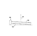
本発明の例示的な一実施形態において、入力装置は、2つの面すなわち表面上に制御部を有する(図1を参照されたい)。この2つの面は、互いに向かい合っている。一方の面102が上に面する向きのときには、他方の面104は下に面する向きである。入力装置は、どちらの面が上に面するかを検知することができるセンサ106を含む。入力装置は、上に面する向きの制御部のみを使用可能にする。装置をひっくり返すと、他方の組の制御部がアクティブ(作動中)になり、第1の組の制御部はイナクティブ(非作動中)になる。面の向きは、それが面する方向として表すことができる。面の面する方向は、一般的に、制御部を含む平面と垂直であり、装置から外向きに延びている。ベクトル110は、面102についての面する方向である。
In one exemplary embodiment of the invention, the input device has controls on two sides or surfaces (see FIG. 1). The two faces face each other. When one
例示的な一実施形態において、センサ106は、装置の一方の面上に搭載された圧力スイッチである。センサ面が下に面する向きである場合には、このスイッチが押し下げられ、対応する組の制御部をイナクティブにするべきであるということを示す。センサ面が上に面する向きである場合には、このスイッチは押し下げられず、対応する組の制御部をアクティブにするべきであるということを示す。他の例示的な実施形態において、スイッチは、重力によって作動するスイッチ(図示せず)、例えば、水銀スイッチや固体(ソリッドステート、solid-state)加速度計である。重力によって作動するスイッチは、1つの表面が略下に面する向きであるときに「オン」になり、その表面が略上に面する向きであるときに「オフ」になる。他の実施形態において、センサは磁気センサ(図示せず)であってもよい。磁気センサは、地球の磁場を用いて、装置の向きを検知する。
In one exemplary embodiment,
本発明の例示的な一実施形態において、装置は、ある表面上に支えられた状態で動作するよう構成されている。例えば、制御部が下に面する向きである場合には、キーすなわち制御部は引っ込み、装置がそのような制御部上に支えられないようになっている。他の例示的な実施形態において、装置は、下に面する向きの制御部のうちのいくつかまたはすべての上に支えられるよう、構成されている。 In one exemplary embodiment of the invention, the device is configured to operate supported on a surface. For example, if the controls are in a downward-facing orientation, the keys or controls will retract so that the device will not be supported on such controls. In other exemplary embodiments, the device is configured to be supported on some or all of the down-facing controls.
例示的な一実施形態において、入力装置が有する制御部は、一方の面上のほうが他方の面上よりも多い。例えば、第1の面は、完全な1組の制御部を含み、制御されている装置のすべての機能にアクセスすることができる。第2の表面上にある1組の制御部は、限定されており、装置の基本機能にアクセスすることができる。 In one exemplary embodiment, the input device has more controls on one surface than on the other surface. For example, the first side includes a complete set of controls and can access all functions of the device being controlled. A set of controls on the second surface is limited and has access to the basic functions of the device.
本発明の例示的な一実施形態において、装置は、手持ち式(ハンドヘルド、hand held)装置、例えばリモコンとして動作するよう構成されている。本実施形態において、1つの表面上の制御部は、第1の装置の制御用である。第2の表面上の制御部は、第2の装置の制御用である。例えば、1つの表面上の制御部はテレビ用であり、他の表面上の制御部は、VCRの制御用である。この例示的な実施形態において、制御部は、2つよりも多い面(あるいは表面)上にあってもよい。図2Aは、装置の3つの面210、212、214上に制御部を有する、長方形の装置を示す。装置におけるセンサは、3つの面のうちのどれが所定の向きであるか、例えば、どの面が上に面しているかを検知する。上に面する制御部が使用可能になる。上に面していない面上の制御部は、使用不可能になる。ユーザが軸204に沿って装置を回転させると、新しい組の制御部が、上に面する制御部になり、この新しく向いた制御部がアクティブになる。この例示的な実施形態において、装置の形状は長方形以外であってもよい。例えば、制御部を有する6つの表面に加えて前端部と後端部があってもよい(図3を参照されたい)。本発明の例示的な一実施形態において、それぞれの表面上に、インジケータ、例えばライト、を配置してもよい。表面上の制御部がアクティブのときには、インジケータが信号で知らせる。例えば、表面上の制御部がアクティブのときには、その表面上のライトが点灯する。他の表面上のライトは点灯しない。これは、それぞれの表面すなわち面上の制御部がアクティブになるときをユーザが確認するのに役立つ。
In one exemplary embodiment of the invention, the device is configured to operate as a handheld device, for example, a remote control. In this embodiment, the controller on one surface is for controlling the first device. The control on the second surface is for controlling the second device. For example, the controls on one surface are for a television and the controls on the other surface are for controlling a VCR. In this exemplary embodiment, the controls may be on more than two surfaces (or surfaces). FIG. 2A shows a rectangular device with controls on the three
この手持ち式の構成において、センサは、1つの軸において他の軸よりも回転に対する感度が高いよう構成されていてもよい。例えば、ユーザが装置を軸204に沿って回転すると、どの表面が上向きであるかの判定は、45度回転した後に行われるようにしてもよい。ユーザがこの装置を直交する軸206を中心として回転すると、装置は、90度回転するまでアクティブな表面が切り換わらないようにしてもよい。これによってユーザは自由に、アクティブな制御部に影響を与えることなく、入力装置を部屋においてさまざまな高さで指す(point)ことができる。本願において、軸204はy軸として規定し、軸206はx軸として規定する。軸204は、制御部を含む各面と略平行な軸である。
In this hand-held configuration, the sensor may be configured to be more sensitive to rotation in one axis than in the other. For example, when the user rotates the device along
本発明の前述の説明は、例示および説明の目的で行った。これは、網羅的であることあるいは本発明を開示した厳密な形式に限定することを意図するものではなく、他の変更および変形が、上記教示に鑑みて可能であるかもしれない。実施形態は、本発明の原理およびその実際の用途を最良に説明し、それによって、他の当業者が本発明をさまざまな実施形態および意図する特定の使用に適合するさまざまな変更形態において最良に利用することができるようにするために、選択し説明した。添付の特許請求の範囲は、従来技術によって限定される範囲を除き、本発明の他の代替の実施形態を含むよう解釈される、ということが意図される。 The foregoing description of the present invention has been presented for purposes of illustration and description. This is not intended to be exhaustive or to limit the invention to the precise form disclosed, and other modifications and variations may be possible in light of the above teachings. The embodiments best describe the principles of the invention and its practical applications, whereby other persons skilled in the art can best understand the invention in various embodiments and various modifications that are adapted to the particular intended use. Selected and described to be available. It is intended that the appended claims be construed to include other alternative embodiments of the invention except insofar as limited by the prior art.
102、104 面
106 センサ
110 面する方向
204,206 軸
210、212、214 面
102, 104
Claims (10)
前記少なくとも2つの面のそれぞれの上に配置されている、少なくとも2つの組の制御部と、
所定の面する方向を向いている前記面を検知するよう構成され、前記所定の面する方向の前記組の制御部が使用可能になるセンサと
を備えることを特徴とする装置。 At least two faces, each having a facing direction, wherein the facing directions for the two faces are different from each other;
At least two sets of controls disposed on each of the at least two faces;
A sensor configured to detect the surface facing in a predetermined facing direction, the sensor being enabled by the set of controls in the predetermined facing direction.
少なくとも1つの制御部を有し、前記第1の表面とは異なる方向を向いた、第2の表面と、
どの表面が上に面する向きであるかを判定するよう構成されたセンサであって、それによって前記上に面する表面上の前記少なくとも1つの制御部が使用可能になる、センサと
を備えることを特徴とする装置。 A first surface having at least one control;
A second surface, having at least one control, facing a different direction than the first surface;
A sensor configured to determine which surface is in the up-facing orientation, whereby the at least one control on the up-facing surface is enabled. An apparatus characterized by the above.
少なくとも1つの制御部を有し、前記第1の表面とは異なる方向を向いた、第2の表面と、
どの表面が上に面する向きであるかを判定する手段であって、それによって前記上に面する表面上の前記少なくとも1つの制御部が使用可能になる手段と
を備えることを特徴とする装置。 A first surface having at least one control;
A second surface, having at least one control, facing a different direction than the first surface;
Means for determining which surface is in the up-facing orientation, thereby enabling the at least one control on the up-facing surface. .
Applications Claiming Priority (1)
| Application Number | Priority Date | Filing Date | Title |
|---|---|---|---|
| US10/339,078 US6717075B1 (en) | 2003-01-08 | 2003-01-08 | Method and apparatus for a multi-sided input device |
Publications (2)
| Publication Number | Publication Date |
|---|---|
| JP2004213667A true JP2004213667A (en) | 2004-07-29 |
| JP2004213667A5 JP2004213667A5 (en) | 2005-06-09 |
Family
ID=32030514
Family Applications (1)
| Application Number | Title | Priority Date | Filing Date |
|---|---|---|---|
| JP2004000120A Pending JP2004213667A (en) | 2003-01-08 | 2004-01-05 | Method and apparatus for multi-sided input device |
Country Status (2)
| Country | Link |
|---|---|
| US (1) | US6717075B1 (en) |
| JP (1) | JP2004213667A (en) |
Families Citing this family (19)
| Publication number | Priority date | Publication date | Assignee | Title |
|---|---|---|---|---|
| WO2007005015A1 (en) * | 2005-06-29 | 2007-01-11 | Thomson Licensing S. A. | Remote control device for entertainment systems with spatially-separated functions |
| US20070013658A1 (en) * | 2005-07-14 | 2007-01-18 | Huan-Wen Chien | Wireless indicating apparatus |
| US8932135B2 (en) * | 2007-04-19 | 2015-01-13 | Adam W. Coe | Game controller |
| USD787606S1 (en) | 2008-02-15 | 2017-05-23 | Evil Controllers LLC | Game controller |
| US8011842B2 (en) * | 2008-04-28 | 2011-09-06 | Wilson Robert D | Apparatus for ergonomic typing |
| KR101885764B1 (en) * | 2011-03-10 | 2018-08-06 | 삼성전자주식회사 | Remote control apparatus |
| US8698745B2 (en) * | 2011-05-20 | 2014-04-15 | Echostar Technologies L.L.C. | Configuring the functionality of control elements of a control device based on orientation |
| US10147564B2 (en) | 2013-02-07 | 2018-12-04 | Universal Electronics Inc. | System and methods for providing orientation compensation in pointing devices |
| US9939934B2 (en) | 2014-01-17 | 2018-04-10 | Osterhout Group, Inc. | External user interface for head worn computing |
| US10254856B2 (en) | 2014-01-17 | 2019-04-09 | Osterhout Group, Inc. | External user interface for head worn computing |
| US9810906B2 (en) | 2014-06-17 | 2017-11-07 | Osterhout Group, Inc. | External user interface for head worn computing |
| US10139966B2 (en) | 2015-07-22 | 2018-11-27 | Osterhout Group, Inc. | External user interface for head worn computing |
| US11003246B2 (en) | 2015-07-22 | 2021-05-11 | Mentor Acquisition One, Llc | External user interface for head worn computing |
| US20170100664A1 (en) * | 2015-10-12 | 2017-04-13 | Osterhout Group, Inc. | External user interface for head worn computing |
| US10466491B2 (en) | 2016-06-01 | 2019-11-05 | Mentor Acquisition One, Llc | Modular systems for head-worn computers |
| US10684478B2 (en) | 2016-05-09 | 2020-06-16 | Mentor Acquisition One, Llc | User interface systems for head-worn computers |
| US10824253B2 (en) | 2016-05-09 | 2020-11-03 | Mentor Acquisition One, Llc | User interface systems for head-worn computers |
| WO2018067166A1 (en) * | 2016-10-07 | 2018-04-12 | Hewlett-Packard Development Company, L.P. | User-input devices |
| US10152141B1 (en) | 2017-08-18 | 2018-12-11 | Osterhout Group, Inc. | Controller movement tracking with light emitters |
Family Cites Families (8)
| Publication number | Priority date | Publication date | Assignee | Title |
|---|---|---|---|---|
| DE3445891A1 (en) * | 1984-12-15 | 1986-06-19 | Grundig E.M.V. Elektro-Mechanische Versuchsanstalt Max Grundig & Co KG, 8510 Fürth | DEVICE FOR REMOTE CONTROL OF SEVERAL AUDIO AND VIDEO DEVICES |
| EP0500794A4 (en) * | 1989-11-22 | 1993-02-03 | David C. Russell | Computer control system |
| US6072470A (en) * | 1996-08-14 | 2000-06-06 | Sony Corporation | Remote control apparatus |
| US5949401A (en) * | 1996-11-21 | 1999-09-07 | Kazarian; Randal N. | Two-handed input apparatus and method |
| US5874906A (en) * | 1997-09-22 | 1999-02-23 | Wilnel, Inc. | Data entry system |
| US6429846B2 (en) * | 1998-06-23 | 2002-08-06 | Immersion Corporation | Haptic feedback for touchpads and other touch controls |
| US6545667B1 (en) * | 1999-08-23 | 2003-04-08 | David M. Lilenfield | Apparatus for a convenient and comfortable cursor control device |
| US6573854B1 (en) * | 2000-05-08 | 2003-06-03 | Philippe Hug | Ergonomic remote control |
-
2003
- 2003-01-08 US US10/339,078 patent/US6717075B1/en not_active Expired - Lifetime
-
2004
- 2004-01-05 JP JP2004000120A patent/JP2004213667A/en active Pending
Also Published As
| Publication number | Publication date |
|---|---|
| US6717075B1 (en) | 2004-04-06 |
Similar Documents
| Publication | Publication Date | Title |
|---|---|---|
| JP2004213667A (en) | Method and apparatus for multi-sided input device | |
| US11755127B2 (en) | Multi-sensor device with an accelerometer for enabling user interaction through sound or image | |
| US6798429B2 (en) | Intuitive mobile device interface to virtual spaces | |
| US6839049B1 (en) | Physically interacting with a processor-based display | |
| EP2677741A1 (en) | Remote control apparatus and control method thereof | |
| KR101192514B1 (en) | Free space pointing devices with tilt compensation and improved usability | |
| JP5258558B2 (en) | Method for control of equipment | |
| US8988342B2 (en) | Display apparatus, remote controlling apparatus and control method thereof | |
| US20040095317A1 (en) | Method and apparatus of universal remote pointing control for home entertainment system and computer | |
| WO2004072818A3 (en) | Interactive handheld apparatus with stylus | |
| JP2006323823A (en) | Sound-based virtual keyboard, device and method | |
| US20130093675A1 (en) | Remote controllable image display system, controller, and processing method therefor | |
| CA2483268A1 (en) | Method and apparatus for navigating an image using a touchscreen | |
| JP2005518005A5 (en) | ||
| JP2007535776A5 (en) | ||
| JP2009100366A (en) | Remote control device, remote control system and electrical device | |
| EP3037936B1 (en) | Image projection apparatus, and system employing interactive input-output capability | |
| JP5135404B2 (en) | Information processing device | |
| CN204945943U (en) | For providing the remote control equipment of remote control signal for external display device | |
| JP2003337962A5 (en) | ||
| JP2011065512A (en) | Information processing system, information processing program, operation recognition system, and operation recognition program | |
| WO2013022000A1 (en) | Electronic device | |
| JPS60138628A (en) | Screen indication input device | |
| US7872634B2 (en) | Status sensing mechanism and the cursor-control device applying the same | |
| JP2004086511A (en) | Electronic equipment and pointer moving method |
Legal Events
| Date | Code | Title | Description |
|---|---|---|---|
| A521 | Request for written amendment filed |
Free format text: JAPANESE INTERMEDIATE CODE: A523 Effective date: 20041029 |
|
| A977 | Report on retrieval |
Free format text: JAPANESE INTERMEDIATE CODE: A971007 Effective date: 20060216 |
|
| A131 | Notification of reasons for refusal |
Free format text: JAPANESE INTERMEDIATE CODE: A131 Effective date: 20060221 |
|
| A02 | Decision of refusal |
Free format text: JAPANESE INTERMEDIATE CODE: A02 Effective date: 20070403 |