JP2004209552A - Transfer device - Google Patents
Transfer device Download PDFInfo
- Publication number
- JP2004209552A JP2004209552A JP2002378741A JP2002378741A JP2004209552A JP 2004209552 A JP2004209552 A JP 2004209552A JP 2002378741 A JP2002378741 A JP 2002378741A JP 2002378741 A JP2002378741 A JP 2002378741A JP 2004209552 A JP2004209552 A JP 2004209552A
- Authority
- JP
- Japan
- Prior art keywords
- workpiece
- robot
- robots
- transfer device
- fingers
- Prior art date
- Legal status (The legal status is an assumption and is not a legal conclusion. Google has not performed a legal analysis and makes no representation as to the accuracy of the status listed.)
- Pending
Links
- 238000003754 machining Methods 0.000 claims description 4
- 238000011144 upstream manufacturing Methods 0.000 abstract description 11
- 230000006866 deterioration Effects 0.000 abstract 2
- 230000002542 deteriorative effect Effects 0.000 abstract 1
- 210000000707 wrist Anatomy 0.000 description 8
- 230000007423 decrease Effects 0.000 description 5
- 230000000694 effects Effects 0.000 description 3
- 239000002184 metal Substances 0.000 description 1
- 230000000414 obstructive effect Effects 0.000 description 1
Images


Landscapes
- Manipulator (AREA)
Abstract
Description
【0001】
【発明の属する技術分野】
本発明は、ワークを搬送するトランスファ装置に関するものである。
【0002】
【従来の技術】
ワーク搬送装置をプレス機械に貫通させて前後方向に配備し、フィンガをプレス機の前方に出せる構造にしたものがある。すなわち、型段替え時にフィードバーが邪魔にならないように片持ちフィードバーを採用し、その片持ちフィードバーに吸着具を固定して、その吸着具でワークを吸着して搬送している(特許文献1参照)。
【0003】
【特許文献1】
特開2001−300661号公報(図1)
【0004】
【発明が解決しようとする課題】
しかしながら、特許文献1では、いわゆる片持ちの吸着具でワークを吸着する構成であるため、ワークを確実に吸着させるためには、ある程度の保持時間が必要である。このため、プレス機の動作が一旦停止される。その結果、プレス機の稼働率が低下するとともに、生産性も低下する。
【0005】
また、金型を交換する場合には、まずフィンガを退避させる。その後、上型と下型とを嵌合させた状態で、金型交換台までスライド移動させて、新しい金型と交換する。このため、金型を交換する際には、必ずフィンガを退避させければならない。従って、金型の交換を容易に行うことはできない。
【0006】
さらに、フィンガを交換する際には、フィードバーの先端部をプレス機の前方に押出して、フィンガを交換しなければならない。その結果、フィンガの交換も容易に行うことはできない。
【0007】
本発明は、このような問題点に着目してなされたものであって、その目的は、稼働率を低下させることのないトランスファ装置を提供することにある。
【0008】
【課題を解決するための手段】
上記の目的を達成するために、請求項1に記載の発明では、フィンガを備えた対向する一対の多関節ロボットと、一対の多関節ロボットのフィンガにワークを挟持させて移動させる制御手段とを備えた。
【0009】
請求項2に記載の発明では、請求項1に記載のトランスファ装置において、一対の多関節ロボットは、ワークを搬送するコンベアの搬送方向に直交して配設されている。
【0010】
請求項3に記載の発明では、請求項1または請求項2に記載のトランスファ装置において、一対の多関節ロボットのうち、一方の多関節ロボットは、天井から吊設されている。
【0011】
請求項4に記載の発明では、請求項1〜請求項3のいずれか1項に記載のトランスファ装置において、一対の多関節ロボットのうち、他方の多関節ロボットは、ワークを加工する加工装置の内部に配設されている。
【0012】
請求項5に記載の発明では、請求項4に記載のトランスファ装置において、他方の多関節ロボットは、加工装置の内外に移動可能な移動手段に載置されている。
【0013】
【発明の実施の形態】
以下に、本発明に係るトランスファ装置をプレス機のワーク搬送装置に具体化した一実施形態について図面を用いて説明する。
【0014】
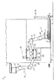
図1、図3に示すように、トランスファ装置1は、一対の6軸垂直多関節ロボット(以下、ロボット)2,3を備えている。ロボット2は、プレス機4の内部に配設されている。すなわち、ロボット2は、移動手段としての台車5に載置された状態でプレス機4の内部にボルト(図示略)で固定されている。従って、ロボット2をメンテナンスする場合等には、台車5とともにプレス機4の内部から外部に引き出すことができる。一方、ロボット3は、ロボット2と対向する位置の天井(図示略)から吊設されている。具体的には、図1に示すように、ロボット3は、プレス機4の前面側であって、ワーク6を搬送するコンベア7の搬送方向に直交するとともに、ロボット2と対向する天井に配設されている。
【0015】
図1に示すように、プレス機4は、上型41と下型42とからなる金型を備えている。上下型41,42は、それぞれ上ダイセット43、下ダイセット44を介して、スライド45、ボルスタ46に固定されている。プレス機4の前面側には、上下型41,42を交換する際に使用する金型引出レール47が配設されている。
【0016】
図1、図3に示すように、ロボット2,3は、コントロールケーブル(図示略)を介してそれぞれコントローラ8,9に接続されている。また、コントローラ8,9同士もネットワークケーブル(図示略)を介して接続されている。ロボット2,3は、制御手段としてのコントローラ8,9で制御される。具体的には、コントローラ8,9により、ロボット2,3が協調動作される。すなわち、例えばロボット2がマスターロボットとして制御され、他方のロボット3がスレーブロボットとして協調動作が行われる。
【0017】
ここで、ロボット2は、ロボット3と同様な構成であるため、ロボット3について説明する。
図1に示すように、ロボット3は、腕11と手首12とを備えている。腕11は、第1関節J1で旋回し、第2関節J2で前後し、第3関節J3で上下する。手首12は、第4関節J4で回転し、第5関節J5で曲がり、第6関節J6で捻られる。
【0018】
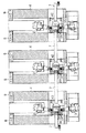
図3に示すように、手首12の先端には、フィードバー20を介してフィンガ30が配設されている。すなわち、フィードバー20には、上流側の第1フィンガ31と下流側の第2フィンガ32とが配設されている。
【0019】
次に、ロボット2,3の動作について説明する。
図3に示すように、上流側のコンベア7に載置されているワーク6がコンベア7の端部に達すると、対向するロボット2,3は、それぞれ第1フィンガ31をワーク6に向かって前進させる。そして、図2に示すように、対向するロボット2,3は、それぞれ第1フィンガ31でワーク6を挟持して上方へ移動させる。このとき、プレス機4でプレス加工されたワーク6も同時にそれぞれ第2フィンガ32で挟持された状態で上方へ移動される。そして、対向するロボット2,3は、2つのワーク6を上方へ移動させながら下流側にも移動させる。続いて、対向するロボット2,3は、2つのワーク6を下方へ移動させながら下流側にも移動させる。
【0020】
図4に示すように、対向するロボット2,3は、それぞれ第1フィンガ31で挟持したワーク6がプレス機4のプレス加工位置まで達すると、対向するロボット2,3は、それぞれ第1フィンガ31で挟持しているワーク6を下方へ移動させる。このとき、第2フィンガ32で挟持しているワーク6は、下流側のコンベア7の端部に達する。そして、図1に示すように、対向するロボット2,3は、第1及び第2フィンガ31,32を後退させると、ワーク6の挟持状態が解除される。その結果、第1及び第2フィンガ31,32で挟持されていたワーク6が、プレス機4のプレス加工の位置と、下流側のコンベア7の端部とに載置される。
【0021】
従って、ロボット2,3は、第1及び第2フィンガ31,32でワーク6を上流側から下流側に向かって、3次元方向に移動させている。つまり、最短距離となるようにワーク6を上流側から下流側に移動させている。
【0022】
図5に示すように、ロボット2、3及びプレス機4を左右方向に連続して配置した場合でも、プレス機4同士の間には、コンベア7を配設するのみである。このため、プレス機4同士の間隔を極力短くすることができる。従って、プレス機4をほぼ連続して配置することができる。
【0023】
次に、上下型41,42を交換するときのロボット2,3の動作について説明する。
まず、コントローラ9を操作して、ロボット3を退避させる。すなわち、コントローラ9からの操作により、ロボット3の腕11及び手首12が、第1関節J1〜第6関節J6で曲げられる(図1に示す2点鎖線)。その結果、ロボット3が退避される。
【0024】
続いて、上下型41,42を交換する場合には、上型41が上ダイセット43とともにスライド45から取り外される。その結果、上ダイセット43とともに上型41が下型42と嵌合される。この状態で、下ダイセット44がボルスタ46から取り外される。そして、上下型41,42は、両ダイセット43,44とともに、金型引出レール47上に移動される。このとき、既にロボット3は、コントローラ9からの操作により、腕11及び手首12が後方に退避されている。このため、上下型41,42を交換する場合であっても、ロボット3が邪魔になることはない。従って、上下型41,42からなる金型を容易に交換することができる。
【0025】
また、コントローラ9からの操作により、ロボット3の腕11及び手首12を所定位置、例えば対向するロボット2の反対方向に退避させれば、フィンガ30を容易に交換することができる。なお、フィンガ30の交換は、ロボット2に対しても同様である。
【0026】
以上、詳述したように本実施形態によれば、次のような作用、効果を得ることができる。
(1)対向する一対のロボット2,3は、ワーク6を挟持するフィンガ30を備えている。一対のロボット2,3は、上流側のコンベア7で搬送されてきたワーク6をフィンガ30で挟持して、そのワーク6を上流側から下流側に向かって、3次元方向に移動させている。すなわち、ワーク6を対向するフィンガ30で挟持する構成である。このため、素早くワーク6を上流側から下流側に移動させることができる。その結果、ワーク6を移動するためにプレス機4の動作を一旦停止させる必要はない。従って、プレス機4の稼働率が低下することはなく、生産性が低下することもない。
【0027】
(2)上下型41,42を交換する場合には、コントローラ8,9を操作して、ロボット2,3の腕11及び手首12を第1関節J1〜第6関節J6で曲げられる。このため、上下型41,42を両ダイセット43,44とともに、金型引出レール47上に移動することができる。その結果、ロボット2,3が邪魔になることはない。従って、上下型41,42からなる金型を容易に交換することができる。
【0028】
(3)コントローラ9からの操作により、ロボット3の腕11及び手首12を所定位置、例えば対向するロボット2の反対方向に退避させることができる。その結果、フィンガ30を容易に交換することができる。なお、フィンガ30の交換は、ロボット2に対しても同様である。従って、フィンガ30の交換に伴う生産性の低下を抑制することができる。
【0029】
(4)ロボット2,3が有するフィンガ30でワーク6を挟持する構成である。このため、いわゆる片持ちの吸着具でワーク6を吸着する構成に比較して、対向するフィンガ30でワーク6を確実に把持することができる。従って、効率良くワーク6を上流側から下流側に移動させることができる。
【0030】
なお、前記実施形態は、次のように変更して具体化することも可能である。
・ロボット3をプレス機4の前面側であって、ワーク6を搬送するコンベア7の搬送方向に直交するとともに、ロボット2と対向する床に配設する構成にしても良い。なお、この場合において、上下型41,42を交換する場合を考慮すると、ロボット3の退避時の高さは、ボルスタ46の上面よりも低いことが好ましい。このように構成すれば、上下型41,42からなる金型の交換時にロボット3が邪魔になることはない。
【0031】
・ロボット2,3は、6軸垂直多関節ロボットに限らず、ワーク6を3次元方向に移動可能な多関節ロボットであれば良い。
【0032】
【発明の効果】
本発明は、以上のように構成されているため、次のような効果を奏する。
請求項1〜請求項5のいずれか1項に記載の発明によれば、稼働率を低下させることのないトランスファ装置を提供することができる。
【図面の簡単な説明】
【図1】対向する一対のロボットとプレス機とを示す側面図。
【図2】ワークを挟持した状態を示す側面図。
【図3】ワークの搬送前を示す平面図。
【図4】ワークの搬送後を示す平面図。
【図5】ロボット及びプレス機を左右方向に連続して配置したときの平面図。
【符号の説明】
1…トランスファ装置、2,3…多関節ロボットとしての6軸垂直多関節ロボット、4…加工装置としてのプレス機、5…移動手段としての台車、6…ワーク、7…コンベア、8,9…制御手段としてのコントローラ、30…フィンガ、31…第1フィンガ、32…第2フィンガ。[0001]
BACKGROUND OF THE INVENTION
The present invention relates to a transfer device that conveys a workpiece.
[0002]
[Prior art]
There is a structure in which the work conveying device is penetrated through a press machine and arranged in the front-rear direction so that the fingers can be put out in front of the press machine. In other words, a cantilever feed bar is adopted so that the feed bar does not get in the way when changing molds, and a suction tool is fixed to the cantilever feed bar, and the workpiece is sucked and transported by the suction tool (patent) Reference 1).
[0003]
[Patent Document 1]
Japanese Patent Laid-Open No. 2001-300661 (FIG. 1)
[0004]
[Problems to be solved by the invention]
However, in Patent Document 1, since the workpiece is sucked by a so-called cantilever suction tool, a certain amount of holding time is required to reliably suck the workpiece. For this reason, the operation of the press machine is temporarily stopped. As a result, the operating rate of the press machine decreases, and the productivity also decreases.
[0005]
When replacing the mold, the finger is first retracted. Thereafter, in a state where the upper mold and the lower mold are fitted, they are slid and moved to a mold exchanging table to exchange with a new mold. For this reason, when replacing the mold, the fingers must be retracted. Therefore, the mold cannot be easily replaced.
[0006]
Furthermore, when replacing the finger, the tip of the feed bar must be pushed forward of the press to replace the finger. As a result, the fingers cannot be easily replaced.
[0007]
The present invention has been made paying attention to such problems, and an object of the present invention is to provide a transfer device that does not reduce the operating rate.
[0008]
[Means for Solving the Problems]
In order to achieve the above object, according to the first aspect of the present invention, there is provided a pair of opposed articulated robots having fingers and a control means for moving a workpiece while holding the workpiece between the fingers of the pair of articulated robots. Prepared.
[0009]
According to a second aspect of the present invention, in the transfer device according to the first aspect, the pair of articulated robots are disposed orthogonal to the conveying direction of the conveyor that conveys the workpiece.
[0010]
According to a third aspect of the present invention, in the transfer device according to the first or second aspect, of the pair of multi-joint robots, one multi-joint robot is suspended from the ceiling.
[0011]
According to a fourth aspect of the present invention, in the transfer device according to any one of the first to third aspects, of the pair of multi-joint robots, the other multi-joint robot is a machining apparatus for machining a workpiece. Arranged inside.
[0012]
According to a fifth aspect of the present invention, in the transfer device according to the fourth aspect, the other articulated robot is placed on a moving means that can move in and out of the processing apparatus.
[0013]
DETAILED DESCRIPTION OF THE INVENTION
Hereinafter, an embodiment in which a transfer device according to the present invention is embodied in a work transfer device of a press machine will be described with reference to the drawings.
[0014]
As shown in FIGS. 1 and 3, the transfer device 1 includes a pair of 6-axis vertical articulated robots (hereinafter referred to as robots) 2 and 3. The
[0015]
As shown in FIG. 1, the
[0016]
As shown in FIGS. 1 and 3, the
[0017]
Here, since the
As shown in FIG. 1, the
[0018]
As shown in FIG. 3, a
[0019]
Next, the operation of the
As shown in FIG. 3, when the workpiece 6 placed on the
[0020]
As shown in FIG. 4, when the workpieces 6 sandwiched between the first fingers 31 reach the pressing positions of the
[0021]
Therefore, the
[0022]
As shown in FIG. 5, even when the
[0023]
Next, the operation of the
First, the
[0024]
Subsequently, when exchanging the upper and
[0025]
Further, if the
[0026]
As described above, according to the present embodiment, the following operations and effects can be obtained.
(1) The pair of
[0027]
(2) When the upper and
[0028]
(3) By the operation from the
[0029]
(4) The work 6 is sandwiched between
[0030]
In addition, the said embodiment can also be changed and actualized as follows.
The
[0031]
The
[0032]
【The invention's effect】
Since this invention is comprised as mentioned above, there exist the following effects.
According to the invention of any one of claims 1 to 5, it is possible to provide a transfer device that does not reduce the operating rate.
[Brief description of the drawings]
FIG. 1 is a side view showing a pair of opposed robots and a press machine.
FIG. 2 is a side view showing a state in which a workpiece is clamped.
FIG. 3 is a plan view showing a work before being conveyed.
FIG. 4 is a plan view showing a state after a workpiece is conveyed.
FIG. 5 is a plan view when a robot and a press machine are continuously arranged in the left-right direction.
[Explanation of symbols]
DESCRIPTION OF SYMBOLS 1 ... Transfer apparatus, 2, 3 ... 6-axis vertical articulated robot as articulated robot, 4 ... Press machine as processing apparatus, 5 ... Dolly as moving means, 6 ... Workpiece, 7 ... Conveyor, 8, 9 ... Controller as control means, 30... Finger, 31... First finger, 32.
Claims (5)
一対の多関節ロボットのフィンガにワークを挟持させて移動させる制御手段とを備えたトランスファ装置。A pair of opposing articulated robots with fingers;
The transfer apparatus provided with the control means which clamps and moves a workpiece | work between the fingers of a pair of articulated robots.
一対の多関節ロボットは、ワークを搬送するコンベアの搬送方向に直交して配設されているトランスファ装置。The transfer device according to claim 1,
The pair of articulated robots is a transfer device that is disposed orthogonal to the conveying direction of a conveyor that conveys a workpiece.
一対の多関節ロボットのうち、一方の多関節ロボットは、天井から吊設されているトランスファ装置。The transfer device according to claim 1 or 2,
Of the pair of articulated robots, one articulated robot is a transfer device suspended from the ceiling.
一対の多関節ロボットのうち、他方の多関節ロボットは、ワークを加工する加工装置の内部に配設されているトランスファ装置。In the transfer apparatus of any one of Claims 1-3,
Of the pair of articulated robots, the other articulated robot is a transfer device disposed inside a machining apparatus for machining a workpiece.
他方の多関節ロボットは、加工装置の内外に移動可能な移動手段に載置されているトランスファ装置。The transfer device according to claim 4,
The other articulated robot is a transfer device mounted on a moving means that can move in and out of the processing device.
Priority Applications (1)
| Application Number | Priority Date | Filing Date | Title |
|---|---|---|---|
| JP2002378741A JP2004209552A (en) | 2002-12-26 | 2002-12-26 | Transfer device |
Applications Claiming Priority (1)
| Application Number | Priority Date | Filing Date | Title |
|---|---|---|---|
| JP2002378741A JP2004209552A (en) | 2002-12-26 | 2002-12-26 | Transfer device |
Publications (1)
| Publication Number | Publication Date |
|---|---|
| JP2004209552A true JP2004209552A (en) | 2004-07-29 |
Family
ID=32815485
Family Applications (1)
| Application Number | Title | Priority Date | Filing Date |
|---|---|---|---|
| JP2002378741A Pending JP2004209552A (en) | 2002-12-26 | 2002-12-26 | Transfer device |
Country Status (1)
| Country | Link |
|---|---|
| JP (1) | JP2004209552A (en) |
Cited By (2)
| Publication number | Priority date | Publication date | Assignee | Title |
|---|---|---|---|---|
| CN103846906A (en) * | 2012-12-03 | 2014-06-11 | 株式会社安川电机 | Robot |
| WO2020004209A1 (en) | 2018-06-25 | 2020-01-02 | 川崎重工業株式会社 | Robot control system |
-
2002
- 2002-12-26 JP JP2002378741A patent/JP2004209552A/en active Pending
Cited By (4)
| Publication number | Priority date | Publication date | Assignee | Title |
|---|---|---|---|---|
| CN103846906A (en) * | 2012-12-03 | 2014-06-11 | 株式会社安川电机 | Robot |
| JP2014108487A (en) * | 2012-12-03 | 2014-06-12 | Yaskawa Electric Corp | Robot |
| WO2020004209A1 (en) | 2018-06-25 | 2020-01-02 | 川崎重工業株式会社 | Robot control system |
| KR20210011420A (en) | 2018-06-25 | 2021-02-01 | 카와사키 주코교 카부시키 카이샤 | Robot control system |
Similar Documents
| Publication | Publication Date | Title |
|---|---|---|
| JP6591940B2 (en) | Transfer robot | |
| US10300520B2 (en) | Workpiece conveying apparatus for a pressing machine with two robots | |
| KR102448070B1 (en) | banding machine | |
| WO2014038337A1 (en) | Workpiece processing device and method for moving mold in workpiece processing device | |
| JP6444958B2 (en) | Transfer robot | |
| WO2012063710A1 (en) | Robot hand for bending long material, and system for bending long material | |
| JP2009208080A (en) | Workpiece conveying device | |
| JP2007069333A (en) | Robot hand, robot and welding method | |
| JPS61103625A (en) | Panel former | |
| JP4906266B2 (en) | Work transfer device | |
| JP2004209552A (en) | Transfer device | |
| JP2016007609A (en) | Workpiece clamp device of workpiece operation robot and method of the same | |
| JP4367692B2 (en) | Bending machine | |
| JP7358616B2 (en) | Transfer method, operating system and bending device configured for the purpose | |
| CN211945281U (en) | Rotary grabbing device and processing equipment | |
| JP5173378B2 (en) | Work transfer robot | |
| JP5444415B2 (en) | Work transfer robot | |
| JP4699634B2 (en) | Method and apparatus for replacing workpiece holding means of transfer feeder | |
| JP6568765B2 (en) | Workpiece continuous processing system | |
| WO2019171561A1 (en) | Clamp structure of manipulator and method of bending sheet material using same | |
| KR20160101514A (en) | System for transferring parts using robot having gripper | |
| JPH0647136B2 (en) | Work feeding device for press working | |
| JP2019084552A (en) | Panel bender | |
| JP3924278B2 (en) | Transfer device and workpiece holding device | |
| JP2582180B2 (en) | Transfer press transfer device |
Legal Events
| Date | Code | Title | Description |
|---|---|---|---|
| A977 | Report on retrieval |
Free format text: JAPANESE INTERMEDIATE CODE: A971007 Effective date: 20050624 |
|
| A131 | Notification of reasons for refusal |
Effective date: 20050705 Free format text: JAPANESE INTERMEDIATE CODE: A131 |
|
| A02 | Decision of refusal |
Free format text: JAPANESE INTERMEDIATE CODE: A02 Effective date: 20051101 |