JP2004207931A - Image display device, image display method and broadcasting receiving apparatus - Google Patents
Image display device, image display method and broadcasting receiving apparatus Download PDFInfo
- Publication number
- JP2004207931A JP2004207931A JP2002373514A JP2002373514A JP2004207931A JP 2004207931 A JP2004207931 A JP 2004207931A JP 2002373514 A JP2002373514 A JP 2002373514A JP 2002373514 A JP2002373514 A JP 2002373514A JP 2004207931 A JP2004207931 A JP 2004207931A
- Authority
- JP
- Japan
- Prior art keywords
- remote control
- display device
- control code
- video display
- controlling
- Prior art date
- Legal status (The legal status is an assumption and is not a legal conclusion. Google has not performed a legal analysis and makes no representation as to the accuracy of the status listed.)
- Pending
Links
Images


Abstract
Description
【0001】
【発明の属する技術分野】
この発明は、複数の外部機器から出力された映像信号を受信して表示し、また複数の外部機器の動作を制御する映像表示装置、映像表示方法、放送受信装置に関する。
【0002】
【従来の技術】
従来の複数の外部機器から出力された映像信号を受信して表示し、また複数の外部機器の動作を制御する技術は、それぞれIEEE1394に対応した複数の機器を用いてループを形成し、ループに接続された機器選択装置によって選択操作を行い、外部機器を制御している。(例えば特許文献1)。
【0003】
また、従来の複数の外部機器から出力された映像信号を受信して表示し、また複数の外部機器の動作を制御する技術は、IEEE1394ネットワークで接続された複数の機器のリモコン操作を、機器毎にリモコンのキーに割り付けられるべき操作機能の情報を記憶し、リモコンで指定した機器に応じて制御コマンド変換部によりリモコンキーの操作を、指定した機器の対応する操作コマンドに変換することにより、1台のリモコンで複数の制御対象機器の操作を行うようにしている。(例えば特許文献2)。
【0004】
【特許文献1】
特開2002−78040号公報(第4−6頁、図1)
【特許文献2】
特開2001−128263号公報(第6−11頁、図1)
【0005】
【発明が解決しようとする課題】
上記特許文献1および特許文献2の技術は、映像表示装置によって動作が制御される外部機器は、IEEE1394ネットワークで接続されている必要があり、映像表示装置がIEEE1394ネットワークに対応していない外部機器を制御することはできなかった。
【0006】
【課題を解決するための手段】
この発明に係る映像表示装置は、映像表示装置と接続され、映像表示装置によって動作の制御が行われる外部機器が選択される外部機器選択手段と、前記選択された外部機器および映像表示装置の動作を制御するためのリモコンコードが保存されるリモコンコード保存手段と、映像表示装置の動作を制御するための信号を受信する動作制御信号受信部と、前記受信された映像表示装置の動作を制御するための信号を、前記リモコンコード保存手段に保存された外部機器および映像表示装置の動作を制御するためのリモコンコードを参照して、前記選択された外部機器の動作を制御するためのリモコンコードに変換するリモコンコード変換手段と、前記外部機器の動作を制御するために変換されたリモコンコードを出力するリモコンコード出力手段とを備えるように構成している。
【0007】
またこの発明に係る映像表示方法は、映像表示装置によって動作の制御が行われる外部機器が選択されるステップと、前記選択された外部機器および映像表示装置の動作を制御するためのリモコンコードが保存されるステップと、映像表示装置の動作を制御するための信号を受信するステップと、前記受信された映像表示装置の動作を制御するための信号を、保存された外部機器および映像表示装置の動作を制御するためのリモコンコードを参照して、前記選択された外部機器の動作を制御するためのリモコンコードに変換するステップと、前記外部機器の動作を制御するために変換されたリモコンコードを出力するステップとを備えるように構成している。
【0008】
またこの発明に係る放送受信装置は、放送を受信して放送で送信された映像信号を取得する放送受信部と、複数の外部機器から出力された映像信号を受信する映像信号受信部と、前記放送で送信され受信した映像信号および外部機器から出力され受信した映像信号を表示する映像表示部と、放送受信装置と接続され、放送受信装置によって動作の制御が行われる前記複数の外部機器が選択される外部機器選択手段と、前記選択された外部機器および放送受信装置の動作を制御するためのリモコンコードが保存されるリモコンコード保存手段と、放送受信装置の動作を制御するための信号を受信する動作制御信号受信部と、前記受信された放送受信装置の動作を制御するための信号を、前記リモコンコード保存手段に保存された外部機器および映像表示装置の動作を制御するためのリモコンコードを参照して、前記選択された外部機器の動作を制御するためのリモコンコードに変換するリモコンコード変換手段と、前記外部機器の動作を制御するために変換されたリモコンコードを出力するリモコンコード出力手段とを備えるように構成している。
【0009】
【発明の実施の形態】
以下、図面を参照してこの発明に係る実施の形態を説明する。
【0010】
図1はこの発明の実施の形態に係る映像表示装置の構成を示すブロック図である。
【0011】
符号11はBSデジタル放送受信アンテナ、符号12はチューナ、符号13はデジタル放送デコーダ、符号14はリモコン受光部、符号15はCPU、符号16は表示画面作成部、符号17は映像・音声入力端子1、符号18は映像・音声入力端子2、符号20はディスプレーである。
【0012】
ここでは、映像表示装置(放送受信装置)10は、CPU15によって制御されている。
【0013】
図示しない放送局から送信されたBSデジタル放送がBSデジタル放送受信アンテナ11で受信され、BSデジタル放送信号が出力される。
【0014】
BSデジタル放送受信アンテナ11から出力されたBSデジタル放送信号はチューナ12で所定の放送局が選局されて受信され、選局されたBSデジタル放送信号が出力される。このときBSデジタル放送信号はMPEG2等のエンコード処理が施されている。
【0015】
チューナ12から出力されたBSデジタル放送信号はデコーダ13に入力され、MPEG2等のエンコード処理が施されたBSデジタル放送信号のデコード処理が施されて出力される。
【0016】
デコード処理が施されてデコーダ13から出力されたBSデジタル放送信号はディスプレー20へ入力されて、選局されたBSデジタル放送に係る映像および音声が再生出力される。
【0017】
表示画面作成部16ではEPG(Electrical Programmable Guide)等の番組選択画面やデータ放送の表示画面が作成される。表示画面作成部16で作成された表示画面はデコーダ13から出力されたBSデジタル放送信号と重畳され、または切換えてディスプレー20に表示される。
【0018】
リモコン受光部14では後述するTV用リモコン送信機(TV用リモコン)30から送信された制御信号を受信する。リモコン受光部14で受信された制御信号はCPU15へ送信され、制御信号にしたがってCPU15が映像表示装置(放送受信装置)10の制御を行う。
【0019】
映像・音声入力端子1(17)、映像・音声入力端子2(18)は、それぞれ映像表示装置(放送受信装置)10の外部接続機器から送信された映像信号(映像信号および音声信号、以後は両者を総称して映像信号と呼ぶ)等の入力信号が入力される端子である。映像・音声入力端子1(17)、映像・音声入力端子2(18)に入力された映像信号はCPU15に制御され、デコーダ13から出力されたBSデジタル放送信号や表示画面作成部16で作成された表示画面等との重畳または切換えが適宜行われ、ディスプレー20に表示される。
【0020】
尚、上記説明においては、放送の一例としてBSデジタル放送を用いて説明を行ったが、この発明において放送は、BSデジタル放送に限られるものではなく、地上波アナログ放送、BSアナログ放送、CSデジタル放送等の一般的な放送に適用される。
【0021】
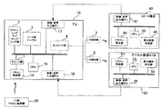
図2は、この発明の実施の形態に係る映像表示装置と外部機器の構成を示すブロック図である。上記説明と同様の構成については同一の符号を付して説明を省力する。
【0022】
符号1はデコード部、符号2はリモコンコードサブサンプリング部、符号3 はコード表テーブル、符号4はエンコード部、符号5はIR送出部、符号6はIR送出部、符号30はTV用リモコン送信機(TV用リモコン)である。
【0023】
まず、ユーザによってTV用リモコン30が操作される。後述するようにTV用リモコン30には、映像表示装置(放送受信装置)10によって動作の制御が行われる外部機器が選択される選択ボタンが備えられている。
【0024】
この外部機器の選択ボタンが選択され場合は、映像表示装置(放送受信装置)10が選択された外部機器の動作の制御を行う。外部機器の選択ボタンが選択されない場合は、通常のTV用リモコンとして動作する。
【0025】
外部機器の選択ボタンが選択されると、受信されたTV用リモコンのリモコンコードを、選択された外部機器を制御するリモコンコードに変換して出力し、選択された外部機器を制御する。
【0026】
例えば、外部機器の選択ボタンが選択される。このとき選択された外部機器はCATV端末(ここでは外部機器1)とする。
【0027】
外部機器1(CATV端末)が選択された後に、ユーザ操作によってリモコンキーが操作され、TV用リモコン30から映像表示装置(放送受信装置)10に向けて赤外光(Infra-red)に変換されたリモコン信号が出力(送信)される。
【0028】
TV用リモコン30から送信されたリモコン信号は、映像表示装置(放送受信装置)10のリモコン受光部14で受光される。リモコン受光部14で受光された赤外光のリモコン信号は、電気信号に変換されてデコード部1へ送信される。
【0029】
デコード部1へ送信されたリモコン信号は、リモコンコード信号へのデコード処理(変換)が行われて出力される。
【0030】
デコード部1から出力されたTV用リモコン30のリモコンコード信号は、CPU15によって、選択された外部機器1のリモコンコード信号に変換される(リモコンコード変換)。
【0031】
すなわち、CPU15によってリモコンコード変換処理が行われ、TV用リモコン30のリモコンコード信号が、選択された外部機器1(CATV端末40)用のリモコンコード信号に変換される。
【0032】
このとき、CPU15は、コード表テーブルに保存されているTV用リモコン30および外部機器1(CATV端末40)のリモコンコード信号を参照して、リモコンコード信号の変換処理を行う。
【0033】
外部機器1(CATV端末40)用に変換されたリモコンコード信号は、エンコード部4へ入力される。エンコード部4へ入力されたリモコンコード信号は、リモコン信号送信用の電気信号に変換されて出力される。
【0034】
ここでは、電気信号に変換されたリモコンコード信号は、IR送出部5へ送信される。IR送出部5では、リモコンコード信号を赤外光に変換して、外部機器1(CATV端末40)に向けて出力する。
【0035】
IR送出部5から出力されたリモコンコード信号は、外部機器1(CATV端末40)のリモコン受光部44で受光される。外部機器1(CATV端末40)は、CATV端末用リモコン41で制御されるの同様に、映像表示装置(放送受信装置)10から送信されるリモコン光によって制御される。
【0036】
符号40はCATV端末(STB)、符号44はリモコン受光部、符号45はCPU、符号46は表示画面作成部、符号47は映像・音声出力端子1である。
【0037】
リモコン受光部44で受光されたリモコンコード信号は、上記と同様にCPU45に送信され、CATV端末(STB)40の動作が制御される。
【0038】
CATV端末(STB)40で受信(図示せず)された映像信号や表示画面作成部46で作成された映像信号は、映像・音声出力端子1(47)を介して映像表示装置10の映像入力端子1(17)へ入力され、上記と同様にディスプレー20に表示される。
【0039】
すなわち、ユーザがTV用リモコン30の外部機器1(CATV端末40)を選択することで、TV用リモコン30を操作して、外部機器1(CATV端末40)を制御することができる。
【0040】
同様に、外部機器の選択ボタンが操作され、デジタル放送STB(外部機器2)が選択されたとする。
【0041】
外部機器2(デジタル放送STB)が選択された後に、ユーザ操作によってリモコンキーが操作され、TV用リモコン30から映像表示装置(放送受信装置)10に向けて赤外光(Infra-red)に変換されたリモコン信号が出力(送信)される。
【0042】
TV用リモコン30から送信されたリモコン信号は、映像表示装置(放送受信装置)10のリモコン受光部14で受光される。リモコン受光部14で受光された赤外光のリモコン信号は、電気信号に変換されてデコード部1へ送信される。
【0043】
デコード部1へ送信されたリモコン信号は、リモコンコード信号へのデコード処理(変換)が行われて出力される。
【0044】
デコード部1から出力されたTV用リモコン30のリモコンコード信号は、CPU15によって、選択された外部機器2(デジタル放送STB)のリモコンコード信号に変換される(リモコンコード変換)。
【0045】
すなわち、CPU15によってリモコンコード変換処理が行われ、TV用リモコン30のリモコンコード信号が、選択された外部機器2(デジタル放送STB)用のリモコンコード信号に変換される。
【0046】
このとき、CPU15は、コード表テーブルに保存されているTV用リモコン30および外部機器2(デジタル放送STB)のリモコンコード信号を参照して、リモコンコード信号の変換処理を行う。
【0047】
外部機器2(デジタル放送STB)用に変換されたリモコンコード信号は、エンコード部4へ入力される。エンコード部4へ入力されたリモコンコード信号は、リモコン信号送信用の電気信号に変換されて出力される。
【0048】
ここでは、電気信号に変換されたリモコンコード信号は、IR送出部6へ送信される。IR送出部6では、リモコンコード信号を赤外光に変換して、外部機器2(デジタル放送STB)に向けて出力する。
【0049】
IR送出部6から出力されたリモコンコード信号は、外部機器2(デジタル放送STB)のリモコン受光部57で受光される。外部機器2(デジタル放送STB)は、デジタル放送STB用リモコン51で制御されるの同様に、映像表示装置(放送受信装置)10から送信されるリモコン光によって制御される。
【0050】
符号50はデジタル放送STB(STB)、符号57はリモコン受光部、符号55はCPU、符号56は表示画面作成部、符号28は映像・音声出力端子1である。
【0051】
リモコン受光部57で受光されたリモコンコード信号は、上記と同様にCPU45に送信され、デジタル放送STB(STB)50の動作が制御される。
【0052】
デジタル放送STB(STB)50で受信(図示せず)された映像信号や表示画面作成部56で作成された映像信号は、映像・音声出力端子2(28)を介して映像表示装置10の映像入力端子2(18)へ入力され、上記と同様にディスプレー20に表示される。
【0053】
すなわち、ユーザがTV用リモコン30の外部機器2(デジタル放送STB)を選択することで、TV用リモコン30を操作して、外部機器2(デジタル放送STB40)を制御することができる。
【0054】
ここで、映像表示装置10のリモコンコードサブサンプリング部2について説明を行う。
【0055】
上記のようにリモコン受光部で受光され、リモコンコードサブサンプリング部2へ入力されたリモコンコード信号は、サブサンプリング処理が行われる。CPU15には、予めリモコンコード信号を受け付ける外部接続機器が設定されている。ここでは、外部接続機器は外部機器1(CATV端末40)、外部機器2(デジタルSTB50)である。すなわち、受信したリモコンコード信号が、外部機器1(CATV端末40)、外部機器2(デジタルSTB50)のいずれかのものに合致するかが確認される。このとき、設定されていない外部接続機器からリモコンコード信号を受信しても、動作しないようにしている。
【0056】
リモコンコードサブサンプリング部2では、リモコンコード信号を受け付けるように設定された外部機器(外部機器1(CATV端末40)または外部機器2(デジタルSTB50))から送信されたリモコンコード信号を受信すると、受信したリモコンコード信号から外部接続機器のを特定する。ここでの特定とは、例えば外部接続機器が○○社製のCATV端末であり、使用されるリモコンコード信号は××××であるというものである。リモコンコード信号は、同一社製の同じように製品であっても異なっている場合がある。このため、この発明の実施の形態においては、特に、リモコンコード信号を特定することが重要である。
【0057】
ここでは、後述するように、CATV端末40用リモコン41やデジタル放送STB用リモコン51から送信されたリモコンコード信号を受信して、受信したリモコンコード信号からCATV端末40やデジタル放送STB用リモコン51で使用されるリモコンコードが特定される。
【0058】
コード表テーブル3には可能な限り、映像表示装置10に外部接続されることが予想される各社製品のリモコンコードが保存されている。
【0059】
図3は、この発明の実施の形態に係る映像表示装置および外部機器の動作の制御を指示するTV用リモコンを示す図である。
【0060】
符号31は外部接続機器1選択ボタン、符号32は外部接続機器2選択ボタン、符号33は外部接続機器3選択ボタンである。ここでは、外部接続機器3は接続されていないので、外部接続機器3選択ボタン33が選択されても動作しない。
【0061】
上記のように、外部接続機器1選択ボタン31、外部接続機器2選択ボタン32、外部接続機器3選択ボタン33を選択操作することで、映像表示装置10によって動作が制御される外部機器が選択される。
【0062】
図4は、この発明の実施の形態に係る映像表示装置へ、映像表示装置によって動作が制御される外部機器が設定されるようすを示す図である。
【0063】
上記のように、CATV端末用リモコンから映像表示装置10に、リモコンコードが送信されると、受信したリモコンコード信号からCATV端末40で使用されるリモコンコードが特定される。
【0064】
図5は、この発明の実施の形態に係る映像表示装置へ、映像表示装置によって動作が制御される外部機器が設定されるようすを示す図である。
【0065】
上記のように、デジタル放送STB用リモコン51から映像表示装置10に、リモコンコードが送信されると、受信したリモコンコード信号からデジタル放送STB用リモコン51で使用されるリモコンコードが特定される。
【0066】
図6は、この発明の、他の実施の形態に係る映像表示装置の構成を示すブロック図である。
【0067】
符号7はIR送出部である。この実施の形態においてはIR送出部7は、複数の外部制御機器に向けて赤外リモコン光が送信されるように構成されている。
【0068】
図7は、この発明の実施の形態に係る映像表示装置へ、映像表示装置によって動作が制御される外部機器が設定されるようすを示すフローチャートである。
【0069】
符号101はここでの開始ステップである。続いて符合102を付したステップへ進む。
【0070】
符号102は映像表示装置10が動作を制御する外部接続機器が選択されたかを判断するステップである。外部接続機器が選択された場合は、符号103を付したステップへ進む(Yes)。外部接続機器が選択されなかった場合は、符号109を付したステップへ進む(No)。
【0071】
符号103は選択された外部接続機器が外部接続機器1(CATV端末)であるか否かを判断するステップである。選択された外部接続機器が外部接続機器1(CATV端末)である場合は、符号104を付したステップへ進む(Yes)。選択された外部接続機器が外部接続機器1(CATV端末)ではない場合は、符号106を付したステップへ進む(No)。
【0072】
符号104はテレビ本体に登録されている外部入力1(CATV端末)のテレビ用リモコンから入力されたリモコンコードを外部入力1(CATV端末)用リモコンコードに変換するステップである。続いて符合105を付したステップへ進む。
【0073】
符号105はテレビ本体から外部入力1(CATV端末)用リモコンコードを出力するステップである。続いて符合109を付したステップへ進む。
【0074】
符号106は選択された外部接続機器が外部接続機器2(デジタル放送STB)であるか否かを判断するステップである。選択された外部接続機器が外部接続機器2(デジタル放送STB)である場合は、符号107を付したステップへ進む(Yes)。選択された外部接続機器が外部接続機器2(デジタル放送STB)ではない場合は、符号109を付したステップへ進む(No)。
【0075】
符号107はテレビ本体に登録されている外部入力2(デジタル放送STB)のコード表テーブルを参照して、テレビ用リモコンから入力されたリモコンコードを外部入力2(デジタル放送STB)用リモコンコードに変換するステップである。続いて符合108を付したステップへ進む。
【0076】
符号108はテレビ本体から外部入力2(デジタル放送STB)用リモコンコードを出力するステップである。続いて符合109を付したステップへ進む。
【0077】
符号109はここでの終了ステップである。このときTV用リモコン30は映像表示装置10の制御を指示する。
【0078】
この発明によれば、映像表示装置によって外部機器の動作を制御することができる。
【0079】
またこの発明によれば、ユーザは、映像表示装置によって動作の制御が行われる外部機器を選択することができる。
【0080】
またこの発明によれば、ユーザは映像表示装置の制御装置を用いて映像表示装置に接続された外部機器を制御することができる。
【0081】
またこの発明によれば、既存の外部機器の動作を、映像表示装置によって制御することができる。
【0082】
【発明の効果】
上記説明したように、この発明によれば、映像表示装置によって外部機器の動作を制御することができる。
【0083】
またこの発明によれば、ユーザは、映像表示装置によって動作の制御が行われる外部機器を選択することができる。
【0084】
またこの発明によれば、ユーザは映像表示装置の制御装置を用いて映像表示装置に接続された外部機器を制御することができる。
【0085】
またこの発明によれば、既存の外部機器の動作を、映像表示装置によって制御することができる。
【図面の簡単な説明】
【図1】この発明の実施の形態に係る映像表示装置の構成を示すブロック図。
【図2】この発明の実施の形態に係る映像表示装置と外部機器の構成を示すブロック図。
【図3】この発明の実施の形態に係る映像表示装置および外部機器の動作の制御を指示するTV用リモコンを示す図。
【図4】この発明の実施の形態に係る映像表示装置へ、映像表示装置によって動作が制御される外部機器が設定されるようすを示す図。
【図5】この発明の実施の形態に係る映像表示装置へ、映像表示装置によって動作が制御される外部機器が設定されるようすを示す図。
【図6】この発明の、他の実施の形態に係る映像表示装置の構成を示すブロック図。
【図7】この発明の実施の形態に係る映像表示装置へ、映像表示装置によって動作が制御される外部機器が設定されるようすを示すフローチャート。
【符号の説明】
1 … デコード部
2 … リモコンコードサブサンプリング部
3 … コード表テーブル
4 … エンコード部
5 … IR送出部
6 … IR送出部
7 … IR送出部
10 … 映像表示装置(放送受信装置)
11 … BSデジタル放送受信アンテナ
12 … チューナ
13 … デジタル放送デコーダ
14 … リモコン受光部
15 … CPU
16 … 表示画面作成部
17 … 映像・音声入力端子1
18 … 映像・音声入力端子2
20 … ディスプレー
28 … 映像・音声出力端子2
30 … TV用リモコン送信機(TV用リモコン)
31 … 外部接続機器1選択ボタン
32 … 外部接続機器2選択ボタン
33 … 外部接続機器3選択ボタン
40 … CATV端末(STB)
44 … リモコン受光部
45 … CPU
46 … 表示画面作成部
47 … 映像・音声出力端子1
50 … デジタル放送STB(STB)
55 … CPU
56 … 表示画面作成部
57 … リモコン受光部[0001]
TECHNICAL FIELD OF THE INVENTION
The present invention relates to a video display device, a video display method, and a broadcast receiving device that receive and display video signals output from a plurality of external devices and control operations of the plurality of external devices.
[0002]
[Prior art]
The conventional technology for receiving and displaying video signals output from a plurality of external devices and controlling the operation of the plurality of external devices is based on a technology that forms a loop using a plurality of devices corresponding to IEEE 1394, and forms a loop. A selection operation is performed by a connected device selection device to control an external device. (For example, Patent Document 1).
[0003]
In addition, a conventional technology for receiving and displaying video signals output from a plurality of external devices and controlling the operation of the plurality of external devices includes a remote control operation of a plurality of devices connected via an IEEE 1394 network. The information of the operation function to be assigned to the key of the remote controller is stored in the remote controller, and the operation of the remote controller key is converted into the corresponding operation command of the specified device by the control command converter in accordance with the device specified by the remote controller. A plurality of control target devices are operated by one remote controller. (For example, Patent Document 2).
[0004]
[Patent Document 1]
JP-A-2002-78040 (page 4-6, FIG. 1)
[Patent Document 2]
JP 2001-128263 A (page 6-11, FIG. 1)
[0005]
[Problems to be solved by the invention]
According to the techniques of
[0006]
[Means for Solving the Problems]
An image display device according to the present invention is connected to an image display device, an external device selecting means for selecting an external device whose operation is controlled by the image display device, and an operation of the selected external device and operation of the image display device. Remote control code storing means for storing a remote control code for controlling the video display device, an operation control signal receiving unit for receiving a signal for controlling the operation of the video display device, and controlling the received video display device operation A signal for controlling the operation of the selected external device with reference to a remote control code for controlling the operation of the external device and the video display device stored in the remote control code storage means. Remote control code conversion means for converting, and a remote control code output for outputting a converted remote control code for controlling the operation of the external device It is configured with the stage.
[0007]
Also, in the video display method according to the present invention, the step of selecting an external device whose operation is controlled by the video display device is stored, and a remote control code for controlling the operation of the selected external device and the video display device is stored. Receiving the signal for controlling the operation of the video display device, and the operation of the external device and the video display device storing the received signal for controlling the operation of the video display device. Referring to a remote control code for controlling the operation of the selected external device, converting the remote control code into a remote control code for controlling the operation of the external device, and outputting the converted remote control code for controlling the operation of the external device And the step of performing
[0008]
Further, the broadcast receiving apparatus according to the present invention is a broadcast receiving unit that receives a broadcast and obtains a video signal transmitted by broadcasting, a video signal receiving unit that receives video signals output from a plurality of external devices, A video display unit for displaying a video signal transmitted and received by broadcasting and a video signal output and received from an external device, and the plurality of external devices connected to a broadcast receiving device and controlled in operation by the broadcast receiving device are selected; External device selecting means, a remote control code storing means for storing a remote control code for controlling the operation of the selected external device and the broadcast receiving apparatus, and a signal for controlling the operation of the broadcast receiving apparatus. An operation control signal receiving unit, and a signal for controlling the operation of the received broadcast receiving apparatus, an external device stored in the remote control code storage unit, A remote control code for controlling the operation of the external device by referring to a remote control code for controlling the operation of the image display device; and converting the remote control code to a remote control code for controlling the operation of the selected external device. And a remote control code output means for outputting the remote control code converted into.
[0009]
BEST MODE FOR CARRYING OUT THE INVENTION
An embodiment according to the present invention will be described below with reference to the drawings.
[0010]
FIG. 1 is a block diagram showing a configuration of a video display device according to an embodiment of the present invention.
[0011]
[0012]
Here, the video display device (broadcast receiving device) 10 is controlled by the
[0013]
A BS digital broadcast transmitted from a broadcast station (not shown) is received by a BS digital
[0014]
The BS digital broadcast signal output from the BS digital
[0015]
The BS digital broadcast signal output from the
[0016]
The BS digital broadcast signal that has been subjected to the decoding process and output from the
[0017]
The display
[0018]
The remote control
[0019]
The video / audio input terminal 1 (17) and the video / audio input terminal 2 (18) are connected to a video signal (video signal and audio signal, hereinafter called a video signal and an audio signal, respectively) transmitted from an externally connected device of the video display device (broadcast receiving device) 10. These are terminals to which input signals such as a video signal are collectively input. The video signals input to the video / audio input terminal 1 (17) and the video / audio input terminal 2 (18) are controlled by the
[0020]
In the above description, BS digital broadcasting has been described as an example of broadcasting. However, in the present invention, broadcasting is not limited to BS digital broadcasting, but terrestrial analog broadcasting, BS analog broadcasting, and CS digital broadcasting. It is applied to general broadcasting such as broadcasting.
[0021]
FIG. 2 is a block diagram showing a configuration of the video display device and the external device according to the embodiment of the present invention. The same components as those described above are denoted by the same reference numerals, and description thereof will be omitted.
[0022]
[0023]
First, the user operates the TV
[0024]
When the external device selection button is selected, the video display device (broadcast receiving device) 10 controls the operation of the selected external device. When the selection button of the external device is not selected, the device operates as a normal TV remote control.
[0025]
When the select button of the external device is selected, the received remote control code of the TV remote controller is converted into a remote control code for controlling the selected external device and output, thereby controlling the selected external device.
[0026]
For example, the selection button of the external device is selected. The external device selected at this time is a CATV terminal (here, external device 1).
[0027]
After the external device 1 (CATV terminal) is selected, a remote control key is operated by a user operation, and is converted from the TV
[0028]
The remote control signal transmitted from the TV
[0029]
The remote control signal transmitted to the
[0030]
The remote control code signal of the TV
[0031]
That is, the remote control code conversion process is performed by the
[0032]
At this time, the
[0033]
The remote control code signal converted for the external device 1 (CATV terminal 40) is input to the
[0034]
Here, the remote control code signal converted into the electric signal is transmitted to the IR transmission unit 5. The IR transmitting section 5 converts the remote control code signal into infrared light and outputs the infrared light to the external device 1 (CATV terminal 40).
[0035]
The remote control code signal output from IR transmitting section 5 is received by remote control
[0036]
[0037]
The remote control code signal received by the remote control
[0038]
The video signal received (not shown) by the CATV terminal (STB) 40 and the video signal created by the display
[0039]
That is, when the user selects the external device 1 (CATV terminal 40) of the
[0040]
Similarly, it is assumed that the selection button of the external device is operated and the digital broadcast STB (the external device 2) is selected.
[0041]
After the external device 2 (digital broadcast STB) is selected, a remote control key is operated by a user operation, and the TV
[0042]
The remote control signal transmitted from the TV
[0043]
The remote control signal transmitted to the
[0044]
The remote control code signal of the TV
[0045]
That is, the remote control code conversion process is performed by the
[0046]
At this time, the
[0047]
The remote control code signal converted for the external device 2 (digital broadcast STB) is input to the
[0048]
Here, the remote control code signal converted into the electric signal is transmitted to the
[0049]
The remote control code signal output from
[0050]
[0051]
The remote control code signal received by the remote control
[0052]
The video signal received by the digital broadcast STB (STB) 50 (not shown) and the video signal created by the display
[0053]
That is, when the user selects the external device 2 (digital broadcast STB) of the
[0054]
Here, the remote control
[0055]
As described above, the remote control code signal received by the remote control light receiving unit and input to the remote control
[0056]
Upon receiving a remote control code signal transmitted from an external device (external device 1 (CATV terminal 40) or external device 2 (digital STB 50)) set to receive the remote control code signal, remote control
[0057]
Here, as described later, the remote control code signal transmitted from the
[0058]
As far as possible, the code table table 3 stores remote control codes of products of various companies that are expected to be externally connected to the
[0059]
FIG. 3 is a diagram showing the video display device according to the embodiment of the present invention and the TV remote controller for instructing control of the operation of the external device.
[0060]
[0061]
As described above, by selecting and operating the
[0062]
FIG. 4 is a diagram showing how an external device whose operation is controlled by the video display device is set to the video display device according to the embodiment of the present invention.
[0063]
As described above, when the remote control code is transmitted from the remote control for the CATV terminal to the
[0064]
FIG. 5 is a diagram showing how an external device whose operation is controlled by the video display device is set to the video display device according to the embodiment of the present invention.
[0065]
As described above, when the remote control code is transmitted from the digital broadcast STB
[0066]
FIG. 6 is a block diagram showing a configuration of a video display device according to another embodiment of the present invention.
[0067]
[0068]
FIG. 7 is a flowchart showing how an external device whose operation is controlled by the video display device is set in the video display device according to the embodiment of the present invention.
[0069]
[0070]
[0071]
[0072]
[0073]
[0074]
[0075]
[0076]
[0077]
[0078]
According to the present invention, the operation of the external device can be controlled by the video display device.
[0079]
Further, according to the present invention, the user can select an external device whose operation is controlled by the video display device.
[0080]
Further, according to the present invention, the user can control an external device connected to the video display device using the control device of the video display device.
[0081]
Further, according to the present invention, the operation of the existing external device can be controlled by the video display device.
[0082]
【The invention's effect】
As described above, according to the present invention, the operation of an external device can be controlled by the video display device.
[0083]
Further, according to the present invention, the user can select an external device whose operation is controlled by the video display device.
[0084]
Further, according to the present invention, the user can control an external device connected to the video display device using the control device of the video display device.
[0085]
Further, according to the present invention, the operation of the existing external device can be controlled by the video display device.
[Brief description of the drawings]
FIG. 1 is a block diagram showing a configuration of a video display device according to an embodiment of the present invention.
FIG. 2 is a block diagram showing a configuration of a video display device and an external device according to the embodiment of the present invention.
FIG. 3 is an exemplary view showing a video display device and a TV remote controller for instructing control of operations of external devices according to the embodiment of the present invention.
FIG. 4 is an exemplary view showing how an external device whose operation is controlled by the video display device is set to the video display device according to the embodiment of the present invention.
FIG. 5 is an exemplary view showing how an external device whose operation is controlled by the video display device is set in the video display device according to the embodiment of the present invention.
FIG. 6 is a block diagram showing a configuration of a video display device according to another embodiment of the present invention.
FIG. 7 is a flowchart showing how an external device whose operation is controlled by the video display device is set in the video display device according to the embodiment of the present invention;
[Explanation of symbols]
DESCRIPTION OF
11 BS digital
16 Display
18 Video /
20: display 28: video /
30 Remote control transmitter for TV (remote control for TV)
31:
44 ... remote control
46: display screen creation unit 47: video /
50 Digital broadcast STB (STB)
55 ... CPU
56: display screen creation unit 57: remote control light receiving unit
Claims (11)
映像表示装置と接続され、映像表示装置によって動作の制御が行われる外部機器が選択される外部機器選択手段と、
前記選択された外部機器および映像表示装置の動作を制御するためのリモコンコードが保存されるリモコンコード保存手段と、
映像表示装置の動作を制御するための信号を受信する動作制御信号受信部と、前記受信された映像表示装置の動作を制御するための信号を、前記リモコンコード保存手段に保存された外部機器および映像表示装置の動作を制御するためのリモコンコードを参照して、前記選択された外部機器の動作を制御するためのリモコンコードに変換するリモコンコード変換手段と、
前記外部機器の動作を制御するために変換されたリモコンコードを出力するリモコンコード出力手段とを備えることを特徴とする映像表示装置。In a video display device that is connected to a plurality of external devices, receives and displays video signals output from the plurality of external devices, and controls the operation of the connected external devices,
External device selection means connected to the video display device, wherein an external device whose operation is controlled by the video display device is selected,
Remote control code storage means in which a remote control code for controlling the operation of the selected external device and the video display device is stored,
An operation control signal receiving unit that receives a signal for controlling the operation of the video display device, and an external device stored in the remote control code storage unit, the received signal for controlling the operation of the video display device, and With reference to a remote control code for controlling the operation of the video display device, remote control code conversion means for converting to a remote control code for controlling the operation of the selected external device,
A video display device, comprising: remote control code output means for outputting a remote control code converted to control the operation of the external device.
映像表示装置と接続され、映像表示装置によって動作の制御が行われる外部機器が選択される外部機器選択手段と、
前記選択された外部機器および映像表示装置の動作を制御するためのリモコンコードが保存されるリモコンコード保存手段と、
映像表示装置の動作を制御するための信号を受信する動作制御信号受信部と、前記受信した映像表示装置の動作を制御するための信号をデコード処理するデコード処理手段と、
前記受信された映像表示装置の動作を制御するための信号を、前記リモコンコード保存手段に保存された外部機器および映像表示装置の動作を制御するためのリモコンコードを参照して、前記選択された外部機器の動作を制御するためのリモコンコードに変換するリモコンコード変換手段と、
前記外部機器の動作を制御するために変換されたリモコンコードをエンコード処理するエンコード手段と、
前記エンコード処理されたリモコンコードを出力するリモコンコード出力手段とを備えることを特徴とする映像表示装置。In a video display device that is connected to a plurality of external devices, receives and displays video signals output from the plurality of external devices, and controls the operation of the connected external devices,
External device selection means connected to the video display device, wherein an external device whose operation is controlled by the video display device is selected,
Remote control code storage means in which a remote control code for controlling the operation of the selected external device and the video display device is stored,
An operation control signal receiving unit that receives a signal for controlling the operation of the video display device, and a decoding processing unit that decodes the received signal for controlling the operation of the video display device;
The received signal for controlling the operation of the video display device, with reference to a remote control code for controlling the operation of the external device and the video display device stored in the remote control code storage means, the selected Remote control code conversion means for converting to a remote control code for controlling the operation of the external device,
Encoding means for encoding the remote control code converted to control the operation of the external device,
A remote control code output unit for outputting the encoded remote control code.
複数の外部機器から出力された映像信号を受信する映像信号受信部と、
前記受信した映像信号を表示する映像表示部と、
映像表示装置と接続され、映像表示装置によって動作の制御が行われる前記複数の外部機器が選択される外部機器選択手段と、
前記選択された外部機器および映像表示装置の動作を制御するためのリモコンコードが保存されるリモコンコード保存手段と、
映像表示装置の動作を制御するための信号を受信する動作制御信号受信部と、前記受信された映像表示装置の動作を制御するための信号を、前記リモコンコード保存手段に保存された外部機器および映像表示装置の動作を制御するためのリモコンコードを参照して、前記選択された外部機器の動作を制御するためのリモコンコードに変換するリモコンコード変換手段と、
前記外部機器の動作を制御するために変換されたリモコンコードを出力するリモコンコード出力手段とを備えることを特徴とする映像表示装置。In a video display device that is connected to a plurality of external devices, receives and displays video signals output from the plurality of external devices, and controls the operation of the connected external devices,
A video signal receiving unit that receives video signals output from a plurality of external devices,
A video display unit for displaying the received video signal,
External device selection means connected to a video display device, wherein the plurality of external devices whose operation is controlled by the video display device are selected,
Remote control code storage means in which a remote control code for controlling the operation of the selected external device and the video display device is stored,
An operation control signal receiving unit that receives a signal for controlling the operation of the video display device, and an external device stored in the remote control code storage unit, the received signal for controlling the operation of the video display device, and With reference to a remote control code for controlling the operation of the video display device, remote control code conversion means for converting to a remote control code for controlling the operation of the selected external device,
A video display device, comprising: remote control code output means for outputting a remote control code converted to control the operation of the external device.
映像表示装置と接続され、映像表示装置に動作が制御される外部機器から送信されるリモコンコードを受信し、受信したリモコンコードに基づいて動作を制御する外部機器を設定する外部機器設定手段と、
前記設定された外部機器の中から映像表示装置によって動作の制御が行われる外部機器が選択される外部機器選択手段と、
前記選択された外部機器および映像表示装置の動作を制御するためのリモコンコードが予め保存されるリモコンコード保存手段と、
映像表示装置の動作を制御するための信号を受信する動作制御信号受信部と、前記受信された映像表示装置の動作を制御するための信号を、前記リモコンコード保存手段に保存された外部機器および映像表示装置の動作を制御するためのリモコンコードを参照して、前記選択された外部機器の動作を制御するためのリモコンコードに変換するリモコンコード変換手段と、
前記外部機器の動作を制御するために変換されたリモコンコードを出力するリモコンコード出力手段とを備えることを特徴とする映像表示装置。In a video display device that is connected to a plurality of external devices, receives and displays video signals output from the plurality of external devices, and controls the operation of the connected external devices,
An external device setting unit connected to the video display device, receiving a remote control code transmitted from an external device whose operation is controlled by the video display device, and setting an external device that controls operation based on the received remote control code,
External device selecting means for selecting an external device whose operation is controlled by the video display device from the set external devices,
Remote control code storage means in which a remote control code for controlling the operation of the selected external device and the video display device is stored in advance,
An operation control signal receiving unit that receives a signal for controlling the operation of the video display device, and an external device stored in the remote control code storage unit, the received signal for controlling the operation of the video display device, and With reference to a remote control code for controlling the operation of the video display device, remote control code conversion means for converting to a remote control code for controlling the operation of the selected external device,
A video display device, comprising: remote control code output means for outputting a remote control code converted to control the operation of the external device.
放送を受信して放送で送信された映像信号を取得する放送受信部と、
複数の外部機器から出力された映像信号を受信する映像信号受信部と、
前記放送で送信され受信した映像信号および外部機器から出力され受信した映像信号を表示する映像表示部と、
放送受信装置と接続され、放送受信装置によって動作の制御が行われる前記複数の外部機器が選択される外部機器選択手段と、
前記選択された外部機器および放送受信装置の動作を制御するためのリモコンコードが保存されるリモコンコード保存手段と、
放送受信装置の動作を制御するための信号を受信する動作制御信号受信部と、前記受信された放送受信装置の動作を制御するための信号を、前記リモコンコード保存手段に保存された外部機器および映像表示装置の動作を制御するためのリモコンコードを参照して、前記選択された外部機器の動作を制御するためのリモコンコードに変換するリモコンコード変換手段と、
前記外部機器の動作を制御するために変換されたリモコンコードを出力するリモコンコード出力手段とを備えることを特徴とする放送受信装置。In a broadcast receiving device connected to a plurality of external devices, receiving and displaying video signals output from the plurality of external devices, and controlling the operation of the connected external devices,
A broadcast receiving unit for receiving a broadcast and acquiring a video signal transmitted by the broadcast,
A video signal receiving unit that receives video signals output from a plurality of external devices,
A video display unit that displays a video signal transmitted and received by the broadcast and a video signal output and received from an external device,
External device selection means connected to a broadcast receiving device, wherein the plurality of external devices for which operation control is performed by the broadcast receiving device are selected,
Remote control code storage means for storing a remote control code for controlling the operation of the selected external device and the broadcast receiving device,
An operation control signal receiving unit that receives a signal for controlling the operation of the broadcast receiving device, and an external device stored in the remote control code storage unit, the signal for controlling the received operation of the broadcast receiving device, With reference to a remote control code for controlling the operation of the video display device, remote control code conversion means for converting to a remote control code for controlling the operation of the selected external device,
A broadcast receiving apparatus comprising: a remote control code output unit that outputs a remote control code converted to control an operation of the external device.
前記選択された外部機器および映像表示装置の動作を制御するためのリモコンコードが保存されるステップと、
映像表示装置の動作を制御するための信号を受信するステップと、
前記受信された映像表示装置の動作を制御するための信号を、保存された外部機器および映像表示装置の動作を制御するためのリモコンコードを参照して、前記選択された外部機器の動作を制御するためのリモコンコードに変換するステップと、
前記外部機器の動作を制御するために変換されたリモコンコードを出力するステップとを備えることを特徴とする映像表示方法。An external device whose operation is controlled by the video display device is selected; and
Remote control code for controlling the operation of the selected external device and the video display device is stored,
Receiving a signal for controlling the operation of the video display device;
The received signal for controlling the operation of the image display device is referred to a stored remote control code for controlling the operation of the external device and the image display device, and the operation of the selected external device is controlled. Converting to a remote control code for performing
Outputting a remote control code converted to control the operation of the external device.
前記選択された外部機器および映像表示装置の動作を制御するためのリモコンコードが保存されるステップと、
映像表示装置の動作を制御するための信号を受信するステップと、
前記受信した映像表示装置の動作を制御するための信号をデコード処理するステップと、
前記受信された映像表示装置の動作を制御するための信号を、保存された外部機器および映像表示装置の動作を制御するためのリモコンコードを参照して、前記選択された外部機器の動作を制御するためのリモコンコードに変換するステップと、
前記外部機器の動作を制御するために変換されたリモコンコードをエンコード処理するステップと、
前記エンコード処理されたリモコンコードを出力するステップとを備えることを特徴とする映像表示方法。An external device whose operation is controlled by the video display device is selected; and
Remote control code for controlling the operation of the selected external device and the video display device is stored,
Receiving a signal for controlling the operation of the video display device;
Decoding the received signal for controlling the operation of the video display device,
The received signal for controlling the operation of the image display device is referred to a stored remote control code for controlling the operation of the external device and the image display device, and the operation of the selected external device is controlled. Converting to a remote control code for performing
Encoding the remote control code converted to control the operation of the external device,
Outputting the encoded remote control code.
前記受信した映像信号を表示するステップと、
映像表示装置によって動作の制御が行われる前記複数の外部機器が選択されるステップと、
前記選択された外部機器および映像表示装置の動作を制御するためのリモコンコードが保存されるステップと、
映像表示装置の動作を制御するための信号を受信するステップと、
前記受信された映像表示装置の動作を制御するための信号を、保存された外部機器および映像表示装置の動作を制御するためのリモコンコードを参照して、前記選択された外部機器の動作を制御するためのリモコンコードに変換するステップと、
前記外部機器の動作を制御するために変換されたリモコンコードを出力するステップとを備えることを特徴とする映像表示方法。Receiving video signals output from a plurality of external devices;
Displaying the received video signal;
A step in which the plurality of external devices whose operation is controlled by the video display device are selected,
Remote control code for controlling the operation of the selected external device and the video display device is stored,
Receiving a signal for controlling the operation of the video display device;
The received signal for controlling the operation of the image display device is referred to a stored remote control code for controlling the operation of the external device and the image display device, and the operation of the selected external device is controlled. Converting to a remote control code for performing
Outputting a remote control code converted to control the operation of the external device.
前記設定された外部機器の中から映像表示装置によって動作の制御が行われる外部機器が選択されるステップと、
前記選択された外部機器および映像表示装置の動作を制御するためのリモコンコードが予め保存されるステップと、
映像表示装置の動作を制御するための信号を受信するステップと、
前記受信された映像表示装置の動作を制御するための信号を、前記リモコンコード保存手段に保存された外部機器および映像表示装置の動作を制御するためのリモコンコードを参照して、前記選択された外部機器の動作を制御するためのリモコンコードに変換するステップと、
前記外部機器の動作を制御するために変換されたリモコンコードを出力するステップとを備えることを特徴とする映像表示方法。Receiving a remote control code transmitted from an external device whose operation is controlled by the video display device, and setting an external device that controls operation based on the received remote control code,
A step in which an external device whose operation is controlled by the video display device is selected from the set external devices,
Remote control code for controlling the operation of the selected external device and the video display device is stored in advance,
Receiving a signal for controlling the operation of the video display device;
The received signal for controlling the operation of the video display device, with reference to a remote control code for controlling the operation of the external device and the video display device stored in the remote control code storage means, the selected Converting to a remote control code for controlling the operation of the external device;
Outputting a remote control code converted to control the operation of the external device.
Priority Applications (1)
| Application Number | Priority Date | Filing Date | Title |
|---|---|---|---|
| JP2002373514A JP2004207931A (en) | 2002-12-25 | 2002-12-25 | Image display device, image display method and broadcasting receiving apparatus |
Applications Claiming Priority (1)
| Application Number | Priority Date | Filing Date | Title |
|---|---|---|---|
| JP2002373514A JP2004207931A (en) | 2002-12-25 | 2002-12-25 | Image display device, image display method and broadcasting receiving apparatus |
Publications (1)
| Publication Number | Publication Date |
|---|---|
| JP2004207931A true JP2004207931A (en) | 2004-07-22 |
Family
ID=32811774
Family Applications (1)
| Application Number | Title | Priority Date | Filing Date |
|---|---|---|---|
| JP2002373514A Pending JP2004207931A (en) | 2002-12-25 | 2002-12-25 | Image display device, image display method and broadcasting receiving apparatus |
Country Status (1)
| Country | Link |
|---|---|
| JP (1) | JP2004207931A (en) |
Cited By (1)
| Publication number | Priority date | Publication date | Assignee | Title |
|---|---|---|---|---|
| JP2007149183A (en) * | 2005-11-25 | 2007-06-14 | Sharp Corp | Voice processor and display device with same |
-
2002
- 2002-12-25 JP JP2002373514A patent/JP2004207931A/en active Pending
Cited By (1)
| Publication number | Priority date | Publication date | Assignee | Title |
|---|---|---|---|---|
| JP2007149183A (en) * | 2005-11-25 | 2007-06-14 | Sharp Corp | Voice processor and display device with same |
Similar Documents
| Publication | Publication Date | Title |
|---|---|---|
| US20140281999A1 (en) | Display device, two-way communication system and display information using method | |
| JP2008079128A (en) | Video display system, and main unit and subunit constituting video display system | |
| WO2004006563A1 (en) | Image display system, image display method and display unit | |
| KR20020008034A (en) | Bi-directional communication system, display apparatus, base apparatus and bi-directional communication method | |
| JP2008147969A (en) | Remote control system | |
| US20090015726A1 (en) | Receiver and receiving system provided therewith | |
| JP3634823B2 (en) | Broadcast receiver | |
| US20090219452A1 (en) | Electronic apparatus and display control method | |
| JP2004187179A (en) | Digital broadcast transmitting and receiving device | |
| JP2004207931A (en) | Image display device, image display method and broadcasting receiving apparatus | |
| WO2004093440A1 (en) | Wireless av system, av system, wireless center, av output device, station selection method, station selection data generation method, control program, and computer-readable recording medium containing the control program | |
| JP2001285965A (en) | Broadcast receiver | |
| JP2004328422A (en) | Controller of content monitor system | |
| KR102051419B1 (en) | Set-top box for displaying multiple programs on a screen | |
| CN101335850A (en) | Image displaying method and display apparatus using the same | |
| JP6950892B2 (en) | Broadcast receiver and content search method | |
| JP2005033602A (en) | Digital broadcast receiving apparatus | |
| JP6915227B2 (en) | Operation device and video playback system | |
| JP4401343B2 (en) | Receiving machine | |
| JP4688429B2 (en) | Digital broadcast receiver | |
| JP2004048312A (en) | Digital broadcast receiver | |
| JP2007235657A (en) | Digital broadcasting receiver | |
| JP2006340111A (en) | Digital broadcast receiving device | |
| JP2006197109A (en) | Broadcast receiving device | |
| KR100594788B1 (en) | Wireless communication system using wireless channel and wireless communication method thereof |
Legal Events
| Date | Code | Title | Description |
|---|---|---|---|
| RD02 | Notification of acceptance of power of attorney |
Free format text: JAPANESE INTERMEDIATE CODE: A7422 Effective date: 20050415 |
|
| RD04 | Notification of resignation of power of attorney |
Free format text: JAPANESE INTERMEDIATE CODE: A7424 Effective date: 20050606 |