JP2004206529A - Automatic adjustment system and key holder for use in the same - Google Patents
Automatic adjustment system and key holder for use in the same Download PDFInfo
- Publication number
- JP2004206529A JP2004206529A JP2002376336A JP2002376336A JP2004206529A JP 2004206529 A JP2004206529 A JP 2004206529A JP 2002376336 A JP2002376336 A JP 2002376336A JP 2002376336 A JP2002376336 A JP 2002376336A JP 2004206529 A JP2004206529 A JP 2004206529A
- Authority
- JP
- Japan
- Prior art keywords
- stopper member
- case
- key holder
- holder
- key
- Prior art date
- Legal status (The legal status is an assumption and is not a legal conclusion. Google has not performed a legal analysis and makes no representation as to the accuracy of the status listed.)
- Pending
Links
Images


Abstract
Description
【0001】
【発明の属する技術分野】
この発明は、主に、低料金ホテル等において用いられる自動精算システムおよびそれに用いられるキーホルダに関する。
【0002】
【従来の技術】
ビジネスホテル等の低料金ホテルにおいては、人件費を節約するため自動精算システムが用いられる。従来の自動精算システムとして、カードキー方式のシステムあるいは暗証番号方式のシステム等が知られている。カードキー方式の自動精算システムは次のようになっている。顧客がホテルのフロントに行くと、フロントの係員が宿泊者名簿の記入を要求し、顧客がその記入を行うと、係員から使い捨ての磁気カードが渡される。顧客がそのカードを料金精算機にセットし、料金を投入すると、磁気カードに所定の記号が書き込まれ、キーとしての使用が可能となる。顧客はそのカードを客室まで持参し、客室ドアに設けられたカード挿入口に挿入すると、ドアのロックが外れ、入室可能となる。
【0003】
しかしながら、このカードキー方式によるシステムには次の問題がある。
▲1▼ドアに取り付けるキーユニットの価格が高い。
▲2▼キーユニットを動作させるための電源(または電池)が必要であること、および使い捨てのカードが必要であることからランニングコストが掛かる。なお、リライト式のカードの場合は、使い捨てカードに比較しランニングコストが少なくなる。
▲3▼既設のホテルに適用する場合、既にドアに取り付けられているシリンダキーが使用できず、新たにキーユニットを取り付けるため高額な投資が必要になる。
【0004】
また、暗証番号方式のシステムは、顧客が自動精算機に料金を投入すると、レシートが発行され、そのレシートに暗証番号が印字されている。顧客はそのレシートを持って客室へ行き、ドアに取り付けられたテンキーユニットによって暗証番号を入力すると、ドアロックが解除される。
この暗証番号方式のシステムも上述したカードキー方式と同様の欠点があると共に、さらに、暗証番号を忘れた時のためレシートを常時保持しないといけないことや、暗証番号の入力が面倒であるという欠点がある。
【0005】
【発明が解決しようとする課題】
この発明は、このような事情を考慮してなされたもので、その目的は、ランニングコストが低くて済み、しかも、既存のホテルに設備する場合においても高額な投資を必要としない自動精算システムおよびそれに用いられるキーホルダを提供することにある。
【0006】
【課題を解決するための手段】
この発明は上記の課題を解決するためになされたもので、請求項1に記載の発明は、ケースと、前記ケースから出没可能なストッパ部材と、常時は前記ストッパ部材を前記ケースから突出した状態で移動不能とし、外部から電源を受けた時前記ストッパ部材を前記ケース内部方向へ移動可能とするストッパ部材駆動機構とを具備するキーホルダと、前記キーホルダが挿入されるキーホルダ挿入口と、金銭投入口とを有し、前記キーホルダが前記キーホルダ挿入口に挿入され、前記金銭投入口から所定の金銭が投入された時前記キーホルダへ電源を出力して前記ストッパ部材を前記ケース内部方向へ移動可能とする精算機と、前記キーホルダが挿入される挿入口を有し、前記ストッパ部材が前記ケース内部方向へ移動可能の状態で前記キーホルダが前記挿入口に挿入された時客室電源をオンとする省エネホルダとを具備することを特徴とする自動精算システムである。
【0007】
請求項2に記載の発明は、請求項1に記載の自動精算システムにおいて、前記ストッパ部材駆動機構は、前記ストッパ部材をケース外部方向へ付勢するバネ部材と、前記ストッパ部材を前記ケースから突出した状態で保持する保持部材と、外部からの電源を受け前記保持部材を外し前記ストッパ部材をケース内部方向へ移動可能とするソレノイドとからなることを特徴とする。
請求項3に記載の発明は、請求項1または請求項2に記載の自動精算システムにおいて、前記キーホルダは特定周波数の無線信号を受けて内部に記憶されている客室番号を送信するICタグを具備し、前記精算機は、前記ICタグに記憶されているIDナンバを読み取る読取手段と、読み取ったIDナンバに基づいて料金を表示する料金表示手段とを具備することを特徴とする。
【0008】
請求項4に記載の発明は、請求項1〜請求項3のいずれかの項に記載の自動精算システムにおいて、前記省エネホルダは、前記キーホルダが挿入された時オンとなるリミットスイッチと、前記リミットスイッチによってオン/オフ制御される電源開閉手段とを具備することを特徴とする。
【0009】
請求項5に記載の発明は、ケースと、前記ケースから出没可能なストッパ部材と、常時は前記ストッパ部材を前記ケースから突出した状態で移動不能とし、外部から電源を受けた時前記ストッパ部材を前記ケース内部方向へ移動可能とするストッパ部材駆動機構とを具備することを特徴とするキーホルダである。
【0010】
請求項6に記載の発明は、請求項5に記載のキーホルダにおいて、前記ストッパ部材駆動機構は、前記ストッパ部材をケース外部方向へ付勢するバネ部材と、前記ストッパ部材を前記ケースから突出した状態で保持する保持部材と、外部からの電源を受け前記保持部材を外し前記ストッパ部材をケース内部方向へ移動可能とするソレノイドとからなることを特徴とする。
【0011】
【発明の実施の形態】
以下、図面を参照し、この発明の一実施の形態について説明する。図1(a)、(b)は共に、同実施の形態による低料金ホテルの自動精算システムにおいて用いられるキーホルダ1の構造を示す一部裁断した平面図、図2は同キーホルダ1の外観図である。図1(a)において、2は半球状のストッパ部材であり、その外周部に形成された突起部2aが軸3に回動自在に係止されている。また、このストッパ部材2の外周部の上記突起部2aに対向する位置には、凸部2bが形成され、この凸部2bに支え棒5の先端が当接している。また、このストッパ部材2はバネ6によってケース8の外部方向へ付勢されており、さらに、球面のかなりの部分がケース8に設けられた孔から外部に突出している。
【0012】
支え棒5は断面円形の細長い棒であり、その他端部においてケース8に回動自在に取り付けられており、また、バネ10によって矢印B方向へ押されている。12はケース8の内部に配置されたソレノイドでありそのロッド12aの先端にカム13の一部が遊びのある状態で取り付けられている。カム13は、略三角形状のカムであり、その一端部が軸14に回動自在に取り付けられており、また、他の端部に操作突起13aが形成されている。そして、この操作突起13aが支え棒5の中央部に当接している。このカム13の、図において下方に設けられた筒状の部材はICタグ17であり、内部にメモリ、制御部、通信部、アンテナを有し、外部からの高周波信号を受けてメモりに予め記憶されているIDナンバを送信する。また、18a、18bはソレノイド12を駆動するための電圧が印加される電極である。
【0013】
このキーホルダ1は、常時は図1(a)の状態にあり、ストッパ部材2の球面部がケース8から突出している。そして、電極18a、18bに直流電圧を加えると、図1(b)に示すように、ソレノイド12が駆動されてロッド12aが突出し、これにより、カム13が軸14を中心にして回転し、操作突起13aが図における下方へ移動する。これにより、支え棒5のカム13による支えが外れ、バネ10の押圧力によって支え棒5が矢印B方向へ移動する。この支え棒5が移動すると、その先端がストッパ部材2の凸部2bから外れ、これにより、ストッパ部材2がケース8の内部に収納可能状態となる。但し、この時、バネ6がストッパ部材2をケース外部方向へ付勢しているので、見た目にはストッパ部材2の状態は変化しない。
なお、図2において、20は表示窓であり、ストッパ部材2が突出固定状態の時は赤色、収納可能状態の時は青色の表示が行われる。
【0014】
図3は料金精算機30の構成を示す正面図である。ホテルの宿泊客はフロントにおいて宿泊者名簿の記入を行った後、係員から上述したキーホルダ1が付いたキーを受け取り、フロントの近くに設置されている料金精算機30においてキーホルダ1をセットした後、料金を投入する。以下、この料金精算機について詳述する。
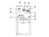
【0015】
図3において、31はキーホルダ1を差し込むキーホルダ挿入口、32は硬貨を投入する硬貨投入口、33は返却ボタン、34は紙幣投入口、35は紙幣排出口、37はレシート発行口、38は硬貨返却口、39は液晶表示器による案内表示器およびタッチ式入力装置、40はスピーカである。
【0016】
図4はこの料金精算機30の電気的構成を示すブロック図である。この図において、41はパーソナルコンピュータ(以下、パソコンという)であり、装置各部を制御する。42はパソコン41へデータ入力を行うためのキーボード等の操作部、43はパソコン41から出力される表示データを表示する液晶表示器による表示部およびデータ入力のためのタッチパネル部、44はパソコン41から出力されるデータを印字するプリンタであり、これらはいずれも料金精算機30内部に設置され、タッチパネルにより宿泊者自身が操作する。
【0017】
50はインターフェイス回路、51はICタグリーダである。このICタグリーダ51はキーホルダ1のICタグ17に記憶されているIDナンバを読み取るための回路であり、予め決められている周波数の高周波信号をアンテナ52を介してICタグ17へ送信し、この信号を受けたICタグから返信される、予め設定されているユニークなIDナンバを取得する。次いで、ICタグリーダ51からパソコン41にIDナンバの問い合わせを行い、パソコン41が予め客室のデータベースをもつホストコンピュータ65へ問い合わせ、ホストコンピュータ65がデータベースを参照し、部屋番号をパソコン41へ出力する。
【0018】
54はキーソレノイド駆動回路であり、電極54a、54bを有している。キーホルダ1がキーホルダ挿入口31に挿入されると、キーホルダ1の電極18a、18bが各々上記電極54a、54bに当接する。そして、このこのキーソレノイド駆動回路54は、パソコン41からインターフェイス回路50を介してソレノイド駆動指令を受けると、電極54a、54b、18a、18bを介してキーホルダ1のソレノイド12へ直流電圧を出力し、ソレノイド12を駆動する。
【0019】
56は金銭処理部であり、硬貨投入口32および紙幣投入口34から投入された貨幣の良否および金額を検出し、検出した貨幣の金額をインターフェイス50を介してパソコン41へ出力する。また、パソコン41から指示されたつり銭の額に相当する金額を紙幣払出口35および硬貨返却口38から払い出す。
57は液晶案内表示部であり、パソコン41から出力される案内表示データを案内表示器39に表示する。60はレシート印刷部であり、パソコン41から出力されるレシートデータに基づいてレシート印刷を行い、印刷したレシートをレシート発行口37から発行する。61はスピーカ駆動部であり、パソコン41から出力される案内音声データに基づいて案内音声を合成し、スピーカ40へ出力する。
【0020】
上述した料金精算機30はフロント内部に設置されたホストコンピュータ65と接続されており、このホストコンピュータ65から出力される各種データに基づいて案内表示、音声案内、料金計算等の各処理を行う。
【0021】
次に、この料金精算機30の動作を説明する。
まず、宿泊客は、フロントにおいて客室キーが付いたキーホルダ1を受け取り、受け取ったキーホルダ1をキーホルダ挿入口31に差し込む。キーホルダ挿入口31にキーホルダ1が差し込まれると、パソコン41がそれを検知し、ICタグリーダ51へ読取指令を出力する。ICタグリーダ51は、その指令を受け、ICタグ17からIDナンバを取得し、パソコン41にホストコンピュータ65が予め持つデータベースを参照するよう指令し、パソコン41が金額の情報を問い合わせ、部屋料金情報を取得する。その結果、例えば次のような表示および音声案内を行う。
ご宿泊ありがとうございます。
客室番号は3階の315番です。
料金は4500円です。
【0022】
ここで、宿泊客が硬貨投入口32および紙幣投入口34から料金を投入すると、投入された金額が金銭処理部56からパソコン41へ出力される。パソコン41はその金額が料金4500円に等しければ、ソレノイド駆動指令をキーソレノイド駆動回路54へ出力する。キーソレノイド駆動回路54はその指令を受け、電極54a、54b間へ直流電圧を出力する。これにより、キーホルダ1内のソレノイド12が駆動され、ストッパ部材2がキーホルダ1のケース8内に収納可能状態となる。次に、パソコン41は、レシートの発行をレシート印刷部60へ指示し、また、次の表示および音声案内を行う。
ありがとうございました。
ごゆっくりお過ごし下さい。
【0023】
ここで、宿泊客はキーホルダ1をキーホルダ挿入口31から抜き取り、それを持って客室へ行く。宿泊客が客室に行き、キーホルダ1の取り付けられたキーによって客室ドアを空け、室内に入ると、すぐ左側の壁に省エネホルダが取り付けられている。以下、この省エネホルダについて説明する。
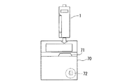
【0024】
図5は省エネホルダ70の正面図である。この省エネホルダ70は、箱状のホルダであり、中央右部にキーホルダ1を挿入する挿入口71が形成されている。この挿入口71はキーホルダ1の外形寸法とほぼ等しく形成されており、この結果、キーホルダ1のストッパ部材2がケース8から突出固定状態においてはキーホルダ1を挿入口71に挿入することができない。ストッパ部材2がケース8内に収納可能状態の時のみ、キーホルダ1を挿入口71から挿入すると、ストッパ部材2がケース8内部方向へ凹み、キーホルダ1を省エネホルダ70内に挿入することができる。
【0025】
また、内部には、リミットスイッチ72および電源を開閉する開閉器(図示略)が設けられている。そして、挿入口70にキーホルダ1を完全に挿入すると、リミットスイッチ72がオンとなり、リミットスイッチ72がオンとなると、上記の開閉器がオンとなって室内の各部に電源が供給される。図6は室内の電気回路の一例を示す回路図であり、リミットスイッチ72がオンとなると開閉器がオンとなり、第1の電源からルームエアコンへ、また、第2の電源から電灯類、浴室、テレビへ各々電源が供給される。
【0026】
次に、団体客の場合について説明する。フロント内部には、団体客用に図7に示す手動解除装置80が設けられている。この手動解除装置80は、小型の箱状をなし、正面上部にキーホルダ1を挿入するキーホルダ挿入口81が設けられ、また、正面下部にはスタートスイッチ82、施錠/解錠切替スイッチ83、手動/自動切替スイッチ84が設けられている。そして、団体客の場合は、予め1つの代表キーに団体全員の合計料金を割当て、その代表キーの料金を料金精算機30のパソコン41内に設定しておく。そして、団体の代表者が料金精算機30によって代表キーの料金を支払った後、係員が各団体員へ渡すべきキーホルダ1を手動解除装置80のキーホルダ挿入口1に順次挿入し、手動/自動切替スイッチ84を手動に、施錠/解錠切替スイッチ83を解錠に投入してスタートボタン82を押す。これにより、キーホルダ1のソレノイド12に直流電圧が印加され、ストッパ部材2がケース8内に収納可能状態とされる。
【0027】
以上がこの発明の一実施形態による自動精算システムの詳細である。上述した自動精算システムによれば、宿泊客が自動精算機30によって宿泊料金を支払うと、キーホルダ1のストッパ部材2がケース8内に収納され、客室の電源が投入可能となり、客室の利用が可能となる。したがって、このシステムによれば、フロントにおいて現金を扱う必要がなく、フロント係員を専門知識を必要としないアルバイトによって手当することが可能となる。また、従来ののシリンダキーを使用することができ、客室ドアに特別な工事をする必要がなく、極めて安価に設置することができる。さらに、使い捨てカード等の特別なランニングコストを必要としない利点も得られる。
【0028】
【発明の効果】
以上説明したように、この発明によれば、ランニングコストが低くて済み、しかも、既存のホテルに設備する場合においても高額な投資を必要としない利点が得られる。また、この発明によれば、フロントの係員が現金を扱わなくて済む利点が得られる。
【図面の簡単な説明】
【図1】この発明の一実施形態による自動精算システムにおいて用いられるキーホルダの構成を示す一部裁断した平面図であり、(a)は支え棒5がストッパ部材2を支えている状態を示す図、(b)は支え棒5が外れた状態を示す図である。
【図2】同キーホルダ1の外観図である。
【図3】同自動精算システムにおいて用いられる料金精算機30の正面図である。
【図4】同料金精算機の電気的構成を示すブロック図である。
【図5】同自動精算システムにおいて用いられる省エネホルダ70の正面図である。
【図6】同省エネホルダ70によって制御される客室電気回路を示す回路図である。
【図7】同自動精算システムにおいて用いられる手動解除装置80の正面図である。
【符号の説明】
1…キーホルダ
2…ストッパ部材
5…支え棒
6…バネ
8…ケース
12…ソレノイド
13…カム
17…ICタグ
30…料金精算機
41…パソコン
51…ICタグリーダ
54…キーソレノイド駆動回路
70…省エネホルダ
72…リミットスイッチ[0001]
TECHNICAL FIELD OF THE INVENTION
The present invention mainly relates to an automatic payment system used in low-priced hotels and the like, and a key holder used therein.
[0002]
[Prior art]
In low-cost hotels, such as business hotels, an automatic payment system is used to save labor costs. As a conventional automatic payment system, a card key system, a password system, and the like are known. The card-key automatic payment system is as follows. When a customer goes to the hotel reception, a receptionist requests entry of a guest list, and when the customer completes the entry, the attendant gives a disposable magnetic card. When the customer sets the card in the charge settlement machine and enters the charge, a predetermined symbol is written on the magnetic card, and the magnetic card can be used as a key. When the customer brings the card to the cabin and inserts the card into the card insertion slot provided in the cabin door, the door is unlocked and the room can be entered.
[0003]
However, the card-key system has the following problems.
(1) The price of the key unit attached to the door is high.
{Circle around (2)} Since a power source (or a battery) for operating the key unit is required and a disposable card is required, a running cost is required. In the case of a rewritable card, the running cost is lower than that of a disposable card.
(3) When applied to an existing hotel, a cylinder key already attached to the door cannot be used, and a large investment is required because a new key unit is attached.
[0004]
Further, in a system using a password, when a customer puts a fee into an automatic checkout machine, a receipt is issued and a password is printed on the receipt. The customer goes to the cabin with the receipt and enters a password using the numeric keypad unit attached to the door, and the door is unlocked.
This password-based system has the same drawbacks as the above-mentioned card key system, and furthermore, the receipt must be kept at all times in case the password is forgotten, and the input of the password is troublesome. There is.
[0005]
[Problems to be solved by the invention]
The present invention has been made in view of such circumstances, and has as its object the purpose of reducing the running cost, and furthermore, an automatic payment system and a system that do not require a large investment even when installing in an existing hotel. It is to provide a key holder used for it.
[0006]
[Means for Solving the Problems]
SUMMARY OF THE INVENTION The present invention has been made to solve the above problems, and the invention according to
[0007]
According to a second aspect of the present invention, in the automatic settlement system according to the first aspect, the stopper member driving mechanism includes a spring member for urging the stopper member toward the outside of the case and the stopper member protruding from the case. And a solenoid that receives the power from the outside and removes the holding member to move the stopper member toward the inside of the case.
According to a third aspect of the present invention, in the automatic payment system according to the first or second aspect, the key holder includes an IC tag that receives a radio signal of a specific frequency and transmits a room number stored therein. The settlement machine includes a reading unit that reads an ID number stored in the IC tag, and a fee display unit that displays a fee based on the read ID number.
[0008]
According to a fourth aspect of the present invention, in the automatic settlement system according to any one of the first to third aspects, the energy saving holder includes a limit switch that is turned on when the key holder is inserted, and the limit switch. Power supply opening / closing means that is turned on / off by a switch.
[0009]
According to a fifth aspect of the present invention, there is provided a case, a stopper member which can come and go from the case, and the stopper member is always immovable in a state protruding from the case, and the stopper member is received when power is supplied from the outside. A key holder, comprising: a stopper member driving mechanism capable of moving in the inner direction of the case.
[0010]
According to a sixth aspect of the present invention, in the key holder according to the fifth aspect, the stopper member driving mechanism includes a spring member for urging the stopper member toward the outside of the case, and the stopper member protruding from the case. And a solenoid that receives the power from the outside and removes the holding member to move the stopper member toward the inside of the case.
[0011]
BEST MODE FOR CARRYING OUT THE INVENTION
Hereinafter, an embodiment of the present invention will be described with reference to the drawings. 1 (a) and 1 (b) are partially cut-away plan views showing the structure of a
[0012]
The
[0013]
The
In FIG. 2,
[0014]
FIG. 3 is a front view showing the structure of the
[0015]
In FIG. 3, 31 is a key holder insertion slot for inserting the
[0016]
FIG. 4 is a block diagram showing an electrical configuration of the
[0017]
50 is an interface circuit, and 51 is an IC tag reader. The
[0018]
[0019]
[0020]
The above-described
[0021]
Next, the operation of the
First, the guest receives the
Thank you for your stay.
The room number is 315 on the third floor.
The fee is 4500 yen.
[0022]
Here, when the guest enters the fee from the
Thank you very much.
Please spend your time slowly.
[0023]
Here, the guest pulls out the
[0024]
FIG. 5 is a front view of the
[0025]
A
[0026]
Next, the case of a group customer will be described. Inside the front, a
[0027]
The above is the details of the automatic payment system according to the embodiment of the present invention. According to the automatic settlement system described above, when the guest pays the accommodation fee by the
[0028]
【The invention's effect】
As described above, according to the present invention, there is obtained an advantage that running costs can be reduced, and even when installing in an existing hotel, a large investment is not required. Further, according to the present invention, there is an advantage that the front staff does not need to handle cash.
[Brief description of the drawings]
FIG. 1 is a partially cutaway plan view showing a configuration of a key holder used in an automatic payment system according to an embodiment of the present invention, and FIG. 1 (a) is a view showing a state in which a
FIG. 2 is an external view of the
FIG. 3 is a front view of a
FIG. 4 is a block diagram showing an electrical configuration of the fee settlement machine.
FIG. 5 is a front view of an
FIG. 6 is a circuit diagram showing a cabin electric circuit controlled by the
FIG. 7 is a front view of a
[Explanation of symbols]
DESCRIPTION OF
Claims (6)
前記キーホルダが挿入されるキーホルダ挿入口と、金銭投入口とを有し、前記キーホルダが前記キーホルダ挿入口に挿入され、前記金銭投入口から所定の金銭が投入された時前記キーホルダへ電源を出力して前記ストッパ部材を前記ケース内部方向へ移動可能とする精算機と、
前記キーホルダが挿入される挿入口を有し、前記ストッパ部材が前記ケース内部方向へ移動可能の状態で前記キーホルダが前記挿入口に挿入された時客室電源をオンとする省エネホルダと、
を具備することを特徴とする自動精算システム。A case, a stopper member that can be retracted from the case, and the stopper member is always immovable in a state protruding from the case, and the stopper member can be moved inward of the case when external power is received. A key holder including a stopper member driving mechanism;
The key holder has a key holder insertion slot into which the key holder is inserted, and a cash slot, and the key holder is inserted into the key holder slot, and outputs power to the key holder when predetermined money is inserted from the money slot. A settlement machine that allows the stopper member to move in the direction toward the inside of the case.
An energy-saving holder having an insertion slot into which the key holder is inserted, and turning on a cabin power supply when the key holder is inserted into the insertion slot in a state in which the stopper member is movable toward the inside of the case.
An automatic settlement system comprising:
前記ケースから出没可能なストッパ部材と、
常時は前記ストッパ部材を前記ケースから突出した状態で移動不能とし、外部から電源を受けた時前記ストッパ部材を前記ケース内部方向へ移動可能とするストッパ部材駆動機構と、
を具備することを特徴とするキーホルダ。Case and
A stopper member that can come and go from the case,
A stopper member driving mechanism that normally disables the stopper member in a state protruding from the case and that can move the stopper member toward the inside of the case when external power is received,
A key holder comprising:
Priority Applications (1)
| Application Number | Priority Date | Filing Date | Title |
|---|---|---|---|
| JP2002376336A JP2004206529A (en) | 2002-12-26 | 2002-12-26 | Automatic adjustment system and key holder for use in the same |
Applications Claiming Priority (1)
| Application Number | Priority Date | Filing Date | Title |
|---|---|---|---|
| JP2002376336A JP2004206529A (en) | 2002-12-26 | 2002-12-26 | Automatic adjustment system and key holder for use in the same |
Publications (1)
| Publication Number | Publication Date |
|---|---|
| JP2004206529A true JP2004206529A (en) | 2004-07-22 |
Family
ID=32813827
Family Applications (1)
| Application Number | Title | Priority Date | Filing Date |
|---|---|---|---|
| JP2002376336A Pending JP2004206529A (en) | 2002-12-26 | 2002-12-26 | Automatic adjustment system and key holder for use in the same |
Country Status (1)
| Country | Link |
|---|---|
| JP (1) | JP2004206529A (en) |
Cited By (1)
| Publication number | Priority date | Publication date | Assignee | Title |
|---|---|---|---|---|
| US9489640B2 (en) | 2006-07-12 | 2016-11-08 | The Nielsen Company (Us), Llc | Methods and systems for compliance confirmation and incentives |
-
2002
- 2002-12-26 JP JP2002376336A patent/JP2004206529A/en active Pending
Cited By (3)
| Publication number | Priority date | Publication date | Assignee | Title |
|---|---|---|---|---|
| US9489640B2 (en) | 2006-07-12 | 2016-11-08 | The Nielsen Company (Us), Llc | Methods and systems for compliance confirmation and incentives |
| US10387618B2 (en) | 2006-07-12 | 2019-08-20 | The Nielsen Company (Us), Llc | Methods and systems for compliance confirmation and incentives |
| US11741431B2 (en) | 2006-07-12 | 2023-08-29 | The Nielsen Company (Us), Llc | Methods and systems for compliance confirmation and incentives |
Similar Documents
| Publication | Publication Date | Title |
|---|---|---|
| AU782694B2 (en) | System for rapidly dispensing and adding value to fare cards | |
| US20180082490A1 (en) | Parking meter and a device therefor | |
| AU785257B2 (en) | Gaming system using a portable gaming device | |
| WO2005010835A1 (en) | System for rapidly dispensing and adding value to fare cards | |
| JP2017205480A (en) | Integrated reset total system for coin laundry | |
| JP2005242550A (en) | Card issuing and control device serving as data entry device | |
| CN105678916A (en) | Internet payment based electronic register cabinet | |
| JP3250998B2 (en) | Keychain with lock mechanism | |
| JP2004206529A (en) | Automatic adjustment system and key holder for use in the same | |
| JP6570228B2 (en) | Peripheral device in store of electronic payment system | |
| WO1979000514A1 (en) | Cash registers | |
| US20230377409A1 (en) | Gaming machine cabinet | |
| JP2000295768A (en) | Combined equipment and input operation equipment | |
| JP4520730B2 (en) | Rental locker system | |
| JP4597029B2 (en) | Locker locking device | |
| US20080196171A1 (en) | Commercial laundry system and method for controlling the same | |
| JPS631636B2 (en) | ||
| JP2004005034A (en) | Commodity sales data processor | |
| JP2774888B2 (en) | Door lock device for key management machine | |
| KR100283820B1 (en) | Integrated management system for ticket examination work | |
| CN110570573B (en) | Lockset with wireless reading head and control method thereof | |
| WO2021230381A1 (en) | Vending machine control device | |
| JPH0581509A (en) | Automatic cash transaction machine installation system | |
| JP2774889B2 (en) | Key management machine | |
| JP7106277B2 (en) | locker system |
Legal Events
| Date | Code | Title | Description |
|---|---|---|---|
| A621 | Written request for application examination |
Free format text: JAPANESE INTERMEDIATE CODE: A621 Effective date: 20051209 |
|
| A977 | Report on retrieval |
Free format text: JAPANESE INTERMEDIATE CODE: A971007 Effective date: 20080626 |
|
| A131 | Notification of reasons for refusal |
Free format text: JAPANESE INTERMEDIATE CODE: A131 Effective date: 20080729 |
|
| A02 | Decision of refusal |
Free format text: JAPANESE INTERMEDIATE CODE: A02 Effective date: 20081202 |