JP2004203152A - Waterdrop removing device for vehicle - Google Patents
Waterdrop removing device for vehicle Download PDFInfo
- Publication number
- JP2004203152A JP2004203152A JP2002373046A JP2002373046A JP2004203152A JP 2004203152 A JP2004203152 A JP 2004203152A JP 2002373046 A JP2002373046 A JP 2002373046A JP 2002373046 A JP2002373046 A JP 2002373046A JP 2004203152 A JP2004203152 A JP 2004203152A
- Authority
- JP
- Japan
- Prior art keywords
- air
- window
- wind
- vehicle
- air outlet
- Prior art date
- Legal status (The legal status is an assumption and is not a legal conclusion. Google has not performed a legal analysis and makes no representation as to the accuracy of the status listed.)
- Pending
Links
- 238000007664 blowing Methods 0.000 claims abstract description 50
- XLYOFNOQVPJJNP-UHFFFAOYSA-N water Substances O XLYOFNOQVPJJNP-UHFFFAOYSA-N 0.000 claims description 91
- 238000001514 detection method Methods 0.000 claims description 26
- 238000009423 ventilation Methods 0.000 claims description 7
- 230000033001 locomotion Effects 0.000 claims description 6
- 230000005540 biological transmission Effects 0.000 abstract description 8
- 239000005357 flat glass Substances 0.000 description 15
- 230000000694 effects Effects 0.000 description 10
- 238000000034 method Methods 0.000 description 6
- 230000006835 compression Effects 0.000 description 3
- 238000007906 compression Methods 0.000 description 3
- 238000010586 diagram Methods 0.000 description 2
- 238000007599 discharging Methods 0.000 description 2
- 238000013459 approach Methods 0.000 description 1
- 230000002238 attenuated effect Effects 0.000 description 1
- 238000005265 energy consumption Methods 0.000 description 1
- 230000000737 periodic effect Effects 0.000 description 1
Images


Classifications
-
- B—PERFORMING OPERATIONS; TRANSPORTING
- B60—VEHICLES IN GENERAL
- B60S—SERVICING, CLEANING, REPAIRING, SUPPORTING, LIFTING, OR MANOEUVRING OF VEHICLES, NOT OTHERWISE PROVIDED FOR
- B60S1/00—Cleaning of vehicles
- B60S1/02—Cleaning windscreens, windows or optical devices
- B60S1/54—Cleaning windscreens, windows or optical devices using gas, e.g. hot air
- B60S1/548—Cleaning windscreens, windows or optical devices using gas, e.g. hot air according to vehicle movement characteristics, e.g. speed, or climatic conditions, e.g. wind
Landscapes
- Engineering & Computer Science (AREA)
- Mechanical Engineering (AREA)
Abstract
Description
【0001】
【発明の属する技術分野】
本発明は、車両、特に自動車の窓の表面に付着する水滴を除去する車両用水滴除去装置に関する。
【0002】
【従来の技術】
従来、車両の窓部(以下、ウィンドーガラス)の表面に付着する雨滴等の水滴を除去する手段には、ワイパーアームの先端に取り付けたゴム製のワイパーブレードをウィンドーガラスの表面に圧接させ、ワイパーアームとともに往復摺動させて水滴を払拭するワイパー装置がある。また、ワイパー装置に比較して、ワイパーアームによる視界の遮蔽や、ワイパーブレードがウィンドーガラス表面を傷つけるのを防止できる、いわゆるエアーワイパーもある(例えば、特許文献1参照)。このエアーワイパーは、空気を圧縮して風を発生させるエアコンプレッサー等の送風手段と、この送風手段に送風ダクトを介して連通すると共に、送風手段で発生した風をウィンドーガラスの表面に吹き付ける吐風口部を備えており、吐風口部から吹き付けた風で、ウィンドーガラス表面に付着した水滴を除去する。
【0003】
通常、この吐風口部はウィンドーガラスの一端部の近傍に配置し、吐出する風がウィンドーガラスの表面を撫でるように、この一端部から、この一端部に対向する他端部に向かって流れるように、吐風口部の吐風角度を調整する。このようにすることで、ウィンドーガラスの表面に付着した水滴は、吐出した風と一緒に、ウィンドーガラス表面を、一端部から他端部に向かって移動し、ウィンドーガラス表面から除去される。例えばエアワイパーを、自動車のフロントウィンドーに取り付けるのであれば、吐風口部は、そのフロントウィンドーの下端部近傍に配設し、フロントウィンドーの下側から上側に向かって空気を吐出するようにする。また、リアウィンドーに設けるのであれば、吐風口部は、そのリアウィンドーの上端部に配設し、そのリアウィンドーの上側から下側に向かって空気を吐出するようにする。このように配設すれば、自動車が前進する場合に自然発生する走行風と相まって、ウィンドーガラス表面に付着した水滴を良好に除去することが可能となる。
【0004】
しかしながら、このエアーワイパーでは、ウィンドーガラス表面のうち、吐出口部が風を吹き付ける部分においては、その空気に勢いがあるため水滴も良好に除去できるが、そのウィンドーガラス表面内でも、風を吹き付けた部分から離間した部分においては、その空気の勢いが減衰しているため、その離間部分に付着した水滴を除去しにくいことがある。これを回避するためには、吹き付ける風の勢いをさらに大きくすればよいのであるが、この場合、勢いの強い風を発生するために空気の圧縮率を増大することが必要となり、圧縮に必要なエネルギー量が増大することになる。
【0005】
また、車両内からの視界を向上させるためには、より多くのウィンドーガラスにエアワイパーを配設することが好ましいが、この場合には吐出する空気量が著しく増加する。この場合においても、各ウィンドーガラスを通しての視界を良好にするためには、上記のように吹き付ける空気の勢いを高く保つことが必要になる。そのため、複数のウィンドーガラスに付着する水滴を除去して視界を良好に保つためには、エアコンプレッサー等を稼動するための電力を膨大に消費することになり、非常に非効率なものであった。
【0006】
【特許文献1】
特開平2−299958号公報
【0007】
【発明が解決しようとする課題】
そこで、本発明は上記問題点に鑑みてなされたもので、その目的とするところは、車両の窓部に付着した水滴を効率的に除去することのできる車両用水滴除去装置を提供することにある。
【0008】
【課題を解決するための手段】
本発明の請求項1に係る車両用水滴除去装置は、複数の窓部を有する車両に取り付けられ、その複数の窓部に付着した水滴を除去する車両用水滴除去装置であって、風を発生する送風手段と、上記複数の窓部のそれぞれに対応させて配設され、その各窓部の表面に、上記送風手段の発生した風を吹き付ける複数の吐風口部と、上記複数の吐風口部及び上記送風手段を個々に連通させる複数の送風流路と、上記車両に関する物理量を検出する検出手段と、上記複数の送風流路の個々に設けられ、上記検出手段の検出した結果に応じて、各送風流路の遮蔽量を自在に調整して、各窓部への風の吹き付け量を調整する複数の遮蔽弁とを備えることを特徴とする。
【0009】
請求項2の発明では、請求項1の発明において、上記検出手段は、車両のギアポジションを検出するギア検出部を有し、上記複数の遮蔽弁は、上記ギア検出部の検出した結果に応じて、各送風流路の遮蔽量を調整することを特徴とする。
【0010】
請求項3の発明では、請求項1又は請求項2の発明において、上記検出手段は、各吐風口部を配設した各窓部の開閉を検出する窓開閉検出部を有すると共に、上記送風手段は、上記窓開閉検出部の検出した結果に応じて風の発生又は停止を切り替えるよう形成されており、上記窓開閉検出部が開閉状態を検出する複数の窓部のうち、少なくとも一つ窓部の開状態を検出した場合には、上記送風手段は風の発生を停止することを特徴とする。
【0011】
請求項4の発明では、車両の略四辺型の窓部に付着した水滴を除去する車両用水滴除去装置であって、上記窓部の表面に圧接されて往復運動するワイパーブレードを有するワイパー装置と、風を発生する送風手段と、窓部の一辺の近傍に配設されると共に、上記ワイパーブレードの運動に連動して、その窓部の表面に、上記一辺部からその一辺部に対向する他辺方向に向かって風を吹き付ける第1の吐風口部と、上記第1の吐風口部及び上記送風手段を連通させる送風流路とを備え、上記第1の吐風口部は、上記ワイパーブレードが上記吐風口部から離間する方向に運動するときに、第1の吐風量で窓部の表面に風を吹き付け、上記ワイパーブレードが上記第1の吐風口部に近接する方向に運動するときには、上記第1の吐風量より小さい第2の吐風量で、窓部の表面に風を吹き付けることを特徴とする。
【0012】
請求項5の発明では、請求項4に記載の発明において、窓部の上記一辺部に隣接する隣接辺に配設されると共に、上記隣接辺からその隣接辺に対向する対向辺方向に向かって風を吹き付ける第2の吐風口部をも備えると共に、上記ワイパーブレードは、窓部の上記一辺及び上記隣接辺間を往復運動し、上記第2の吐風口部は、上記ワイパーブレードがその隣接辺から離間する方向に運動するときに、第1の吐風量で窓部の表面に風を吹き付け、上記ワイパーブレードが上記第2の吐風口部に近接する方向に運動するときには、上記第1の吐風量より小さい第2の吐風量で、窓部の表面に風を吹き付けることを特徴とする。
【0013】
請求項6の発明では、請求項1乃至請求項5のいずれかの発明において、上記送風手段は、窓部の表面に吹き付ける風の圧力が周期的に変化するよう、風を発生することを特徴とする。
【0014】
【発明の実施の形態】
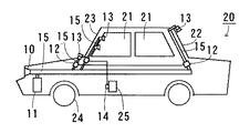
図1は、本発明の請求項1に係る車両用水滴除去装置の一実施の形態を示す図であり、自動車20に取り付けた状態の概観を示している。図1において、11は空気圧縮機、10は走行風取込口、12は遮蔽弁、15は送風流路としての送風ダクト、13は吐風口、14は検出手段としてのギアポジション検知部、21はサイドウィンドー、22はリアウィンドー、23はフロントウィンドー、24はタイヤ、25は変速機を示している。
【0015】
送風手段は、エアコンプレッサー等の空気圧縮機11と走行風取込口10とで構成している。走行風取込口10は、自動車20のボディ前面に形成した外気の取り込み口であり、自動車20が高速走行中にそのボディ前面に当たる走行風を送風ダクト15内に取り込むようにしている。走行風は、自動車20が高速に走行するほど、その勢いが増大し、送風ダクト15に連通する吐風口部13から勢いよく吐出させることができる。すなわち、この走行風取込口10が吐風口部13に送る風は、低速走行時よりも高速走行時に特に有効に作用する。
【0016】
空気圧縮機11は、電力供給により作動し、外気を取り込んで圧縮し、その圧縮した空気を放出して風を発生させる。この空気圧縮機11は、供給する電力に応じて、発生させる風の勢いを変化することができる。従って、この空気圧縮機11により、自動車20が高速走行又は低速走行に関わらず安定して吐風口部13に風を吹き出させることが可能となる。
上記の走行風取込口10及び空気圧縮機11により、吐風口部13から安定して風を吹き出させることができ、また、自動車20が高速走行するほど、より効果的に水滴を除去することが可能となる。
【0017】
送風ダクト15は、配管パイプで形成しており、走行風取込口10及び空気圧縮機11と、自動車20のウィンドーの端部に配設した吐風口部13とを連通している。この送風ダクト15により、走行風取込口10および空気圧縮機11で発生させた風を、吐風口部13に配送することができる。
【0018】
吐風口部13は、自動車20のウィンドーの端部近傍に配設している。図1では、フロントウィンドー23の下端部の近傍と、リアウィンドー22の上端部の近傍と、サイドウィンドー21の側端部の近傍に配設してある。この配設位置は、各ウィンドーに吹き付ける風の勢いが著しく減衰しない程度の距離であれば特に限定するものはなく、フロントウィンドー23であれば、例えば、自動車20のボンネットとフロントウィンドー23との間に配設するようにすればよい。またリアウィンドー22であれば、自動車20の天井部分に配設すればよい。またサイドウィンドー21であれば、ウィンドーを支持する枠体に配設すればよい。
【0019】
ギアポジション検知部14は、自動車20の変速機25に取り付けてあり、その変速機25のギアのポジション、例えば1速、2速、後退などを検出する。
【0020】
遮蔽弁12は、送風ダクト15に設けた弁で、走行風取込口10及び空気圧縮機11から吐風口部13へ至る送風ダクト15内の送風量を、その弁を開放したり絞ったりすることで調整している。この遮蔽弁12を最大に絞った場合には、送風量はゼロとなる。この遮蔽弁12は、ギアポジション検知部14の検出した結果が、例えば1速であれば、全ての遮蔽弁12を開放状態にして、吐風口部13を配設した複数の窓部の全てに風を吹き付ける。また、ギアポジション検知部14の検出した結果が、5速など高速走行用のギア位置であったときには、フロントウィンドー23に対応させて配設した吐風口部13に連通する送風ダクト15のみを開放するようにする。また、ギアポジション検知部14の検出した結果が、後退のギア位置であれば、リアウィンドー22とサイドウィンドー21に連通する送風ダクト15の遮蔽弁12を開放して、後方及び側方の視界が良好になるようにする。このようにすることで、低速走行時はすべてのウィンドーの視界が良好になり、高速走行時には、より重点的に注視すべきフロントウィンドーの視界が良好になる。また後進時には、後方の視界を特に注視するのに必要な、リアウィンドー22及びサイドウィンドー21の視界を良好にすることができる。
【0021】
なお本実施形態において、図2に示すように、検出手段に降雨量を検出する水分検出部16をも備えさせ、上記の走行風取込口10及び空気圧縮機11を、この水分検出部16の検出する結果に応じて、作動又は停止に切り替えさせるようにしてもよい。このようにすれば、雨量がゼロの場合、すなわち晴天時等の雨滴が付着することのないときに誤ってこの水滴除去装置を誤って作動させてしまうことを防止できる。また、雨量を検知したときに自動的に、風を発生させるようにすれば、人為的に操作せずとも視界を良好に保つことが可能となり好ましい。
【0022】
また、図3に示すように、検出手段に、ウィンドーの開閉状態を検出する窓開閉検出部17をも設け、その検出結果に応じて、上記の走行風取込口10及び空気圧縮機11の作動又は停止を切り替えるようにすれば、開いているウィンドーに誤って風を吹き付けさせ、自動車20内に風を吹き込ませてしまうことを防止できる。
【0023】
また、図4に示すように、ウィンドーの表面に圧接した状態で往復摺動するワイパーブレードを有するワイパー装置19をも備えさせ、ウィンドーに付着する水滴をより効率的に除去させるようにしてもよい。さらにこのワイパー装置19の動作を、水滴除去装置の動作に連動させるようにすれば、消費エネルギーを低減させながら、水滴を効率的に除去することができ好ましい。例えば、水滴を除去することが必要な場合において、ワイパー装置19の作動中は、水滴除去装置の動作を停止させる、すなわち交互に動作させるようにすれば、より電力消費を低減させることができる。また、ワイパー装置19と水滴除去装置の動作を同時に作動又は停止させるようにすれば、水滴除去装置の風の吐出/非吐出状態を、ワイパー装置19の動作で視認することができ、無駄に電力を消費するのを防止できる。
【0024】
また、検出手段に自動車20の速度を検出する速度検出部(図示せず)を設けるようにして、自動車20の速度に応じて、吐風口部13に吐出させる風を、走行風取込口10又は空気圧縮機11のいずれか一方に切り替えさせるようにしてもよい。この場合、例えば、速度検出部の検出結果に応じて走行風取込口10に蓋をするシャッター部を設けるようにすればよい。そして、高速走行時には、このシャッター部の蓋を開いて走行風を送風ダクト15内に取り込むと共に、空気圧縮機11への電力供給を停止させる。逆に、低速走行時には、シャッター部の蓋を閉じて走行風取込口10を閉塞すると共に、空気圧縮機11に電力を供給して、送風ダクト15に風を送るようにする。
【0025】
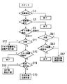
上記の車両用水滴除去装置の動作を示すフローチャートを図5に示す。以下、この図5を参照して、車両用水滴除去装置の動作を説明する。
【0026】
まず、水分検出部16で雨量を検出する(ステップS1)。検出した結果、雨量がゼロであった場合には、水滴除去装置を作動させる必要がないので動作を終了する。一方、雨量がゼロでなく、降雨状態である場合には、ステップS2に移行する。降雨状態である場合において、ウィンドーが開いているか、又は閉じているかを検出する(ステップS2)。もし、ウィンドーが開いていれば、吹き付けた風が車内に入り込む可能性があるので、ここで動作を終了する。ウィンドーが閉じていれば、ステップS3に移行する。
【0027】
このステップS3では、変速機25のギアポジションを検出する。検出した結果、変速機のギアが前進ギアのいずれかに入っていれば、ステップSf1に移行する。前進ギアに入っているとき、水分検出部16の検出結果が大雨である場合には、ワイパー装置19の動作を停止させると共に送風手段の走行風取込口及び空気圧縮装置を作動させる(ステップSf2)。大雨でなければ、そのときワイパー装置19が作動中であるか否かを検出する(ステップSf3)。ワイパー装置19が作動中であれば、ワイパー装置19によりウィンドー越しの視界が良好であると判断して、動作を終了する。もしワイパー装置19が停止していれば、ステップSf4に移行する。ワイパー装置19が停止中の場合、自動車20が高速走行中であるか否かを検出する(ステップSf4)。その検出の結果、自動車20が高速走行中であれば、走行風取込口10を開いて、走行風を取り込み、送風ダクト15及び吐風口部13を介してウィンドーにその取り込んだ走行風を吹き付けさせる(ステップSf6)。もし自動車が低速走行中又は停止中であれば、走行風の勢いは小さいので、送風手段を作動させて勢いのある風を発生させ、送風ダクト15及び吐風口部13を介してウィンドーに、その発生させた風を吹き付けさせる(ステップSf5)。
【0028】
一方、ステップS3において、変速機25のギアが後進ギアに入っていれば、ステップSb1に移行する。後進ギアに入っているとき、水分検出部16が大雨であると検出した場合には、空気圧縮機11を作動させて風を発生させ、送風ダクト15及び吐風口部13を介してリアウィンドー22に、その発生させた風を吹き付けさせる(ステップSb2)。もし大雨でなければ、そのときワイパー装置19が作動中であるか否かを検出する(ステップSb3)。ワイパー装置19が停止中であれば、送風手段を作動させて風を発生させ、送風ダクト15及び吐風口部13を介してリアウィンドー22に、その発生させた風を吹き付けさせる(ステップSb2)。もしワイパー装置19が作動中であれば、そのワイパー装置19によりウィンドー越しの視界が良好に保たれていると判断し、動作を終了する。上記のように動作させることにより、ウィンドー越しの視界を良好にすることが可能となる。
【0029】
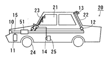
上記の水滴除去装置では、空気圧縮機11及び走行風取込口10からの風をそのまま吐風口部13からウィンドーに吹き付けさせていたが、図6に示すように、空気圧縮機11及び走行風取込口10と吐風口部13を連通させる送風ダクト15にヒーター51を設け、空気圧縮機11及び走行風取込口10からの風を加熱して、吐風口部13から吐出させるようにすれば、ウィンドーが曇ったときに、すみやかにその曇りを取り除くことができ、また、雪がウィンドー上に降ったときや、積雪している場合には、特に、その雪をすみやかにウィンドー上から除去することが可能となり、好ましい。
【0030】
また、水を貯留する貯水部(図示せず)をも備えるようにし、この貯水部と送風ダクト15とを連通するようにすれば、貯水部に貯めた水を、空気圧縮機11及び走行風取込口10からの風に乗せて吐風口部13からウィンドーに噴射させることが可能となる。これは、上記のように送風ダクト15にヒーター51を設けた場合、吐風口部13から噴射する水がヒーター51で加熱されて温水となるので、ウィンドーに積もった雪を溶解させて除去する場合には、特に有効となる。また、雪を溶解して除去するだけでなく、温水により、ウィンドーに付着した汚れをも落とすことが容易となり、好ましい。
【0031】
また、吐風口部13から吹き出す風が、その流速を周期的に変化するように、送風手段から吹き出すようにすれば、一定の勢いの風を吹き付けるよりも効率的に水滴を除去でき、好ましい。変化のさせ方は、例えば、インパルス的に急激に勢いの大きくなる脈動状や、徐々に勢いが大きくなり、その後再び元の勢いに戻るのを繰り返す正弦波状など、適宜設定すればよい。
【0032】
また、本実施形態では、車両用水滴除去装置を適用する車両を自動車としたが、他にも例えば電車、航空機など、窓部を有する移動車両であればどのようなものに適用してもよい。
【0033】
上記のように、自動車20の複数のウィンドーのそれぞれに対応させて配設した複数の吐風口部13のうち、車両に関する物理量に応じて、空気圧縮機11からの風を吹き出させる吐風口部13を切り替えるので、視界を良好に保つのに必要な箇所を、車両の状態に応じて適切に切り替えることができ、効率的に水滴を除去させることが可能となる。
【0034】
図7は、本発明の請求項4に係る車両用水滴除去装置の一実施の形態を示すものであり、23は略四辺型のフロントウィンドー、31はワイパー装置のワイパーブレード、32はフロントウィンドー23の一辺に設けた第1の吐出口部、11は送風手段としての空気圧縮装置、15は送風ダクト、を示している。
【0035】
ワイパーブレード31は、ゴムよりなり、フロントウィンドー23の表面に圧接状態で、その表面を摺動するようにワイパー装置に取着している。このワイパーブレード31は、フロントウィンドー23の下辺23aと、その下辺23aに隣接する側辺23bとの間を往復摺動し、フロントウィンドー23の表面に付着した水滴を、ワイパーブレード31の進行方向の端部にある下辺23a又は側辺23bのいずれかに押し寄せて除去する。
【0036】
吐風口部32は、フロントウィンドー23の下辺23aに配設しており、フロントウィンドー23の表面に、下辺23aから、その下辺23aに対向する上端部方向に向かって、風を吐出する。すなわち、フロントウィンドー23の表面に付着した水滴は、吐風口部32からの風により、フロントウィンドー23の上側方向に移動することになる。この吐風口部32には、蓋(図示せず)が設けてあり、この蓋の開閉度を調整することで、吐風口部32からの吐風量を調整する。蓋により吐風口部32を閉塞した場合には吐風量はゼロとなる。そして、ワイパーブレード31が、フロントウィンドー23の下側から上側に移動中は、その蓋をせず、吐風口部32を開放して第1の吐風量で風を吐出させる。また、ワイパーブレード31が、フロントウィンドー23の表面を上側から下側に移動中は、吐風口部32に蓋をして、第1の吐風量より小さい第2の吐風量で風を吹き出させる。このようにすることで、フロントウィンドー23の下辺23aから吹き出す風により、ワイパーブレード31が下側に移動するとき、その吹き出した風を受けて往復運動に支障をきたさないようにすることが可能となる。また、その吐風口部32の風を吐出する部分32aは複数あり、その複数の部分32aからフロントウィンドー23の表面に風を吐出するようにしている。なお、第2の吐風量は、第1の吐風量より小さければよく、吐風量ゼロ、すなわち無風も含む。
【0037】
送風手段は、エアーコンプレッサー等の空気圧縮機11を備えており、圧縮した空気を放出することで風を発生させる。また、この空気圧縮装置に加えて、自動車が走行中に自然発生する走行風を送風ダクト15内に取り込み、その取り込んだ走行風を吐風口部32から吹き出させるようにしてもよい。
【0038】
送風ダクト15は、配管パイプで形成しており、空気圧縮機11と吐風口部32とを連通させて、空気圧縮機11で発生した風を吐風口部32まで漏れなく配送する。
【0039】
また、本実施形態の別の形態として、図8に示すように、フロントウィンドー23の下辺23aに隣接する隣接辺としての側辺23bにも第2の吐風口部33を備えるようにしてもよい。
【0040】
この吐風口部33は、吐風口部32と同じように、送風ダクト15を介して空気圧縮機11に連通しており、空気圧縮機11が発生させた風を、フロントウィンドー23の表面に、側辺23bから、その側辺23bに対向するもう一方の側端部方向に向かって吹き付ける。また、この吐風口部33にも蓋が設けてあり、この蓋により吐風口部33の全体を閉塞することができる。この蓋により吐風口部33の全体を閉塞すると、空気圧縮機11からの風を、フロントウィンドー23の表面に吹き出さないようにすることが可能となる。
【0041】
このように、フロントウィンドー23の下辺23aと側辺23bに、それぞれ吐風口部32と吐風口部33を設け、ワイパーブレード31の動作と連動させる。それは、ワイパーブレード31が吐風口部32から離間する方向、すなわちフロントウィンドー23の上方向に向かって移動中は、吐風口部32の蓋をせず開放状態にして、第1の吐風量で風を吹き出させる。このとき、吐風口部33には蓋をして閉塞状態にさせ、第2の吐風量で風を吹き出す。
【0042】
逆に、ワイパーブレード31が吐風口部33から離間する方向、すなわちフロントウィンドー23の下方向に向かって移動中は、吐風口部33には蓋をせず、開放状態にして第1の吐風量で風を吹き出させる。このとき吐風口部32には蓋をして閉塞状態にさせ、第2の吐風量で風を吹き出させる。このようにすることで、ワイパーブレード31が移動しようとする方向に向かって風が吹き出すことになると共に、その移動先にある端部からは風が吹き出さないことになるので、吐出口部から吹き出す風で、ワイパーブレード31の往復運動を乱しにくくさせることが可能となると共に、より効率的に水滴を除去させることが可能となる。
【0043】
なお、本実施形態の水滴除去装置の構成を、上記請求項1に係る水滴除去装置に設けるようにして、さらに効率的に水滴を除去させるようにしてもよい。
【0044】
また、吐風口部から吹き出す風が、その流速を周期的に変化するように、送風手段から吹き出すようにすれば、一定の勢いの風を吹き付けるよりも効率的に水滴を除去でき、好ましい。変化のさせ方は、例えば、インパルス的に急激に勢いの大きくなる脈動状や、徐々に勢いが大きくなり、その後再び元の勢いに戻るのを繰り返す正弦波状など、適宜設定すればよい。
【0045】
また、上記ではワイパーブレード31の動作に風の吐出を連動させる際に、吐風口部32,33に蓋を設け、その設けた蓋を開閉することで、風の吐出/非吐出を行なっていたが、これ以外にも例えば、送風ダクト15内に切り替え弁を設け、この切り替え弁で、空気圧縮機11に連通させる吐風口部を、吐風口部32と吐風口部33との間で切り替えるようにしてもよい。
【0046】
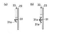
また、図9に示すように、ワイパー装置の形状を、図9(b)に示す形状のように形成するのも好ましい。図9は、車両のフロントウィンドー23の上側方向から、ワイパーブレード31に着目して表した図であり、このときワイパーブレード31はその長手方向が天地となっている。図9(a)は、従来のワイパー装置を示す図であり、通常ワイパー装置には、その下側部分に風除け31aが取着してあり、フロントウィンドー23の下側方向からの風により、ワイパーブレード31がフロントウィンドー23に圧接するようにしている。しかし、吐風口部33からの風も、風除け31aに当たることになるため、吐風口部33からの風を受けた場合には、逆に風除け31aに浮力が生じ、フロントウィンドー23からワイパーブレード31が離れてしまうことがある。そこで、図9(b)のように、ワイパーブレード31の上側にも風除け31aを設ければ、吐風口部33からの風を受けてもワイパーブレード31がフロントウィンドー23から離れることなく、逆により大きな圧力の圧接状態でフロントウィンドー23の表面を摺動することが可能となり、水滴をより多く除去することができ、好ましい。
【0047】
また、上記では、吐風口部32,33をフロントウィンドー23に配設するようにしたが、これはワイパー装置を備えるウィンドーであれば、どのウィンドーであってもよく、例えばリアウィンドー等にも配設すれば、車両の前後の視界が良好となり好ましい。ただしリアウィンドーに適用する場合は、吐風口部32は、リアウィンドーの上端部に配設することが好ましく、このようにすれば車両の走行時に発生する走行風と同じ方向に風を吐出でき、より効率的に水滴を除去することが可能となる。
【0048】
上記のように、ワイパー装置のワイパーブレード31の動作と吐出口部からの風の吹き出し動作とを連動させるようにしたので、ウィンドーに付着した水滴をより効率的に除去することが可能となる。
【0049】
以上、本発明の好適な実施の形態を説明したが、本発明はこの実施の形態に限らず、種々の形態で実施することができる。
【0050】
【発明の効果】
上記のように本発明の請求項1に記載の車両用水滴除去装置は、複数の窓部を有する車両に取り付けられ、その複数の窓部に付着した水滴を除去する車両用水滴除去装置であって、風を発生する送風手段と、上記複数の窓部のそれぞれに対応させて配設され、その各窓部の表面に、上記送風手段の発生した風を吹き付ける複数の吐風口部と、上記複数の吐風口部及び上記送風手段を個々に連通させる複数の送風流路と、上記車両に関する物理量を検出する検出手段と、上記複数の送風流路の個々に設けられ、上記検出手段の検出した結果に応じて、各送風流路の遮蔽量を自在に調整して、各窓部への風の吹き付け量を調整する複数の遮蔽弁とを備えるので、効率的に水滴を除去できる、という効果を奏する。
【0051】
本発明の請求項2に記載の車両用水滴除去装置によれば、請求項1の発明において、上記検出手段は、車両のギアポジションを検出するギア検出部を有し、上記複数の遮蔽弁は、上記ギア検出部の検出した結果に応じて、各送風流路の遮蔽量を調整するので、上記の効果に加えて、より効率的に水滴を除去することができる、という効果を奏する。
【0052】
本発明の請求項3に記載の車両用水滴除去装置によれば、請求項1又は請求項2の発明において、上記検出手段は、各吐風口部を配設した各窓部の開閉を検出する窓開閉検出部を有すると共に、上記送風手段は、上記窓開閉検出部の検出した結果に応じて風の発生又は停止を切り替えるよう形成されており、上記窓開閉検出部が開閉状態を検出する複数の窓部のうち、少なくとも一つ窓部の開状態を検出した場合には、上記送風手段は風の発生を停止するので、上記の効果に加えて、より効率的に水滴を除去することができる、という効果を奏する。
【0053】
本発明の請求項4に記載の車両用水滴除去装置によれば、車両の略四辺型の窓部に付着した水滴を除去する車両用水滴除去装置であって、上記窓部の表面に圧接されて往復運動するワイパーブレードを有するワイパー装置と、風を発生する送風手段と、窓部の一辺の近傍に配設されると共に、上記ワイパーブレードの運動に連動して、その窓部の表面に、上記一辺部からその一辺部に対向する他辺方向に向かって風を吹き付ける第1の吐風口部と、上記第1の吐風口部及び上記送風手段を連通させる送風流路とを備え、上記第1の吐風口部は、上記ワイパーブレードが上記吐風口部から離間する方向に運動するときに、第1の吐風量で窓部の表面に風を吹き付け、上記ワイパーブレードが上記第1の吐風口部に近接する方向に運動するときには、上記第1の吐風量より小さい第2の吐風量で、窓部の表面に風を吹き付けるので、効率的に水滴を除去することができる、という効果を奏する。
【0054】
本発明の請求項5に記載の車両用水滴除去装置によれば、請求項4に記載の発明において、窓部の上記一辺部に隣接する隣接辺に配設されると共に、上記隣接辺からその隣接辺に対向する対向辺方向に向かって風を吹き付ける第2の吐風口部をも備えると共に、上記ワイパーブレードは、窓部の上記一辺及び上記隣接辺間を往復運動し、上記第2の吐風口部は、上記ワイパーブレードがその隣接辺から離間する方向に運動するときに、第1の吐風量で窓部の表面に風を吹き付け、上記ワイパーブレードが上記第2の吐風口部に近接する方向に運動するときには、上記第1の吐風量より小さい第2の吐風量で、窓部の表面に風を吹き付けるので、上記の効果に加えて、より効率的に水滴を除去することができる、という効果を奏する。
【0055】
本発明の請求項6に記載の車両用水滴除去装置によれば、請求項1乃至請求項5のいずれかに記載の発明において、上記送風手段は、窓部の表面に吹き付ける風の圧力が周期的に変化するよう、風を発生するので、上記の効果に加えて、より一層効率的に水滴を除去することができる、という効果を奏する。
【図面の簡単な説明】
【図1】本発明の請求項1に係る車両用水滴除去装置の一実施の形態における概略図である。
【図2】上記車両用水滴除去装置において、水分検出部を設けたことを示す概略図である。
【図3】上記車両用水滴除去装置において、窓開閉検出部を設けたことを示す概略図である。
【図4】上記車両用水滴除去装置において、ワイパー装置を設けたことを示す概略図である。
【図5】上記車両用水滴除去装置の動作を示すフローチャートである。
【図6】上記車両用水滴除去装置において、ヒーターを設けたことを示す概略図である。
【図7】本発明の請求項8に係る車両用水滴除去装置の一実施の形態における概略図である。
【図8】上記車両用水滴除去装置の別の実施の形態を示す概略図である。
【図9】上記車両用水滴除去装置において、ワイパー装置に注目した図である。
【符号の説明】
10 走行風取込口
11 空気圧縮機
12 遮蔽弁
13 吐風口部
14 ギアポジション検知部
15 送風ダクト
16 水分検出部
17 窓開閉検出部
19 ワイパー装置
20 自動車
21 サイドウィンドー
22 リアウィンドー
23 フロントウィンドー
23a 下辺
23b 側辺
25 変速機
31 ワイパーブレード
32 吐風口部
33 吐風口部[0001]
TECHNICAL FIELD OF THE INVENTION
The present invention relates to a water droplet removing device for a vehicle that removes water droplets attached to a surface of a vehicle, particularly, a window of an automobile.
[0002]
[Prior art]
Conventionally, a means for removing water droplets such as raindrops adhering to the surface of a window (hereinafter, window glass) of a vehicle includes pressing a rubber wiper blade attached to a tip of a wiper arm against the surface of the window glass. There is a wiper device that reciprocates with a wiper arm to wipe off water droplets. In addition, there is a so-called air wiper which can prevent the field of view from being shielded by a wiper arm and prevent a wiper blade from damaging the surface of a window glass as compared with a wiper device (for example, see Patent Document 1). The air wiper communicates with a blowing means such as an air compressor for compressing air to generate a wind, and a blowing duct for blowing the wind generated by the blowing means onto the surface of the window glass. A wind port is provided to remove water droplets adhering to the surface of the window glass by wind blown from the air outlet.
[0003]
Normally, the air outlet is disposed near one end of the window glass, and from the one end toward the other end opposite to the one end, so that the wind to be discharged strokes the surface of the window glass. Adjust the blowing angle of the blowing port so that it flows. In this way, water droplets attached to the surface of the window glass, along with the discharged wind, move from the one end to the other end of the window glass surface, and are removed from the window glass surface. You. For example, if an air wiper is attached to the front window of the automobile, the air outlet is disposed near the lower end of the front window so that air is discharged upward from the lower side of the front window. To If provided in the rear window, the air outlet is disposed at the upper end of the rear window so that air is discharged from the upper side to the lower side of the rear window. With this arrangement, it is possible to satisfactorily remove water droplets adhering to the surface of the window glass in combination with the traveling wind naturally generated when the vehicle moves forward.
[0004]
However, with this air wiper, in the part of the window glass surface where the discharge port blows the wind, the air has a momentum, so that the water droplets can be removed satisfactorily. At a portion separated from the sprayed portion, since the force of the air is attenuated, it may be difficult to remove water droplets attached to the separated portion. In order to avoid this, it is only necessary to further increase the force of the blowing wind, but in this case, it is necessary to increase the compression ratio of the air in order to generate a strong force of the wind. The amount of energy will increase.
[0005]
Further, in order to improve the field of view from inside the vehicle, it is preferable to dispose air wipers on more window glasses, but in this case, the amount of air to be discharged is significantly increased. Even in this case, in order to improve the visibility through each window glass, it is necessary to keep the force of the blowing air high as described above. Therefore, in order to remove water droplets adhering to a plurality of window glasses and maintain a good visibility, a large amount of power is consumed for operating an air compressor and the like, which is very inefficient. Was.
[0006]
[Patent Document 1]
JP-A-2-299958
[0007]
[Problems to be solved by the invention]
Therefore, the present invention has been made in view of the above problems, and an object of the present invention is to provide a vehicle water droplet removing device capable of efficiently removing water droplets attached to a vehicle window. is there.
[0008]
[Means for Solving the Problems]
A vehicle water droplet removing device according to claim 1 of the present invention is a vehicle water droplet removing device that is attached to a vehicle having a plurality of windows and removes water droplets attached to the plurality of windows, and generates wind. Blowing means, and a plurality of air outlets disposed in correspondence with each of the plurality of windows, and a plurality of air outlets for blowing the wind generated by the air blowing means on the surface of each of the windows, and the plurality of air outlets And a plurality of air flow paths for individually communicating the air blowing means, a detecting means for detecting a physical quantity related to the vehicle, provided in each of the plurality of air flow paths, according to the detection result of the detecting means, It is characterized by comprising a plurality of shielding valves for freely adjusting the shielding amount of each air flow passage and adjusting the blowing amount of wind to each window.
[0009]
According to a second aspect of the present invention, in the first aspect, the detecting means has a gear detecting section for detecting a gear position of the vehicle, and the plurality of shut-off valves are arranged in accordance with a result detected by the gear detecting section. Thus, the amount of shielding of each air flow path is adjusted.
[0010]
According to a third aspect of the present invention, in the first or second aspect of the present invention, the detecting means has a window opening / closing detecting section for detecting opening / closing of each window provided with each air outlet, and the blowing means Is formed so as to switch the generation or stop of the wind in accordance with the result detected by the window opening / closing detection section, and at least one of the plurality of windows where the window opening / closing detection section detects the open / closed state. When the open state is detected, the blower stops generating the wind.
[0011]
According to a fourth aspect of the present invention, there is provided a water droplet removing device for a vehicle for removing water droplets attached to a substantially quadrilateral window of a vehicle, the wiper having a wiper blade reciprocating by being pressed against the surface of the window. A blower for generating wind, and a wind blower, which is disposed near one side of the window, and which is opposed to the one side from the one side on the surface of the window in conjunction with the movement of the wiper blade. A first air outlet that blows wind in the side direction; and an air flow path that communicates the first air outlet and the air blowing means, wherein the first air outlet is provided by the wiper blade. When moving in the direction away from the air outlet, the first blowing amount blows air to the surface of the window, and when the wiper blade moves in the direction approaching the first air outlet, The first air volume smaller than the first air volume In the 吐風 amount, and wherein the blowing air to the surface of the window portion.
[0012]
According to a fifth aspect of the present invention, in the invention according to the fourth aspect, the window portion is disposed on an adjacent side adjacent to the one side portion, and extends from the adjacent side toward the opposite side facing the adjacent side. A second air outlet for blowing wind is provided, and the wiper blade reciprocates between the one side and the adjacent side of the window, and the second air outlet is formed by the wiper blade adjacent to the adjacent side. When the wiper blade moves in a direction approaching the second air outlet, the first blower blows air to the surface of the window at a first air discharge amount. The method is characterized in that wind is blown to the surface of the window with a second blowout amount smaller than the wind amount.
[0013]
According to a sixth aspect of the present invention, in any one of the first to fifth aspects of the present invention, the blower generates the wind such that the pressure of the wind blown to the surface of the window changes periodically. And
[0014]
BEST MODE FOR CARRYING OUT THE INVENTION
FIG. 1 is a view showing one embodiment of a vehicle water drop removing device according to claim 1 of the present invention, and shows an overview of a state where the device is attached to an
[0015]
The air blowing means includes an
[0016]
The
The traveling
[0017]
The
[0018]
The
[0019]
The
[0020]
The
[0021]
In this embodiment, as shown in FIG. 2, the detecting means is also provided with a
[0022]
As shown in FIG. 3, the detection means is also provided with a window opening /
[0023]
Further, as shown in FIG. 4, a
[0024]
In addition, a speed detecting unit (not shown) for detecting the speed of the
[0025]
FIG. 5 is a flowchart showing the operation of the above-described vehicle water drop removing device. Hereinafter, the operation of the vehicle water droplet removing device will be described with reference to FIG.
[0026]
First, the amount of rain is detected by the moisture detector 16 (step S1). If the result of the detection indicates that the rainfall is zero, the operation ends because there is no need to operate the water droplet removing device. On the other hand, if the rainfall is not zero and it is raining, the process proceeds to step S2. If it is raining, it is detected whether the window is open or closed (step S2). If the window is open, the operation ends here because there is a possibility that the blown wind may enter the vehicle. If the window is closed, the process moves to step S3.
[0027]
In step S3, the gear position of the
[0028]
On the other hand, in step S3, if the gear of the
[0029]
In the above-described water droplet removing device, the wind from the
[0030]
In addition, a water storage unit (not shown) for storing water is provided, and if the water storage unit and the
[0031]
In addition, it is preferable that the air blown out from the
[0032]
Further, in the present embodiment, the vehicle to which the vehicle water droplet removing device is applied is an automobile, but may be applied to any moving vehicle having a window, such as a train or an aircraft. .
[0033]
As described above, out of the plurality of
[0034]
FIG. 7 shows an embodiment of a vehicle water droplet removing device according to claim 4 of the present invention, wherein 23 is a substantially quadrilateral front window, 31 is a wiper blade of a wiper device, and 32 is a front window. A first discharge port provided on one side of the
[0035]
The
[0036]
The
[0037]
The blowing means includes an
[0038]
The
[0039]
As another form of the present embodiment, as shown in FIG. 8, a
[0040]
Like the
[0041]
As described above, the
[0042]
Conversely, while the
[0043]
The configuration of the water droplet removing device according to the present embodiment may be provided in the water droplet removing device according to claim 1 so as to remove water droplets more efficiently.
[0044]
In addition, it is preferable that the air blown from the air outlet be blown out from the blowing means so that the flow velocity changes periodically, since water droplets can be removed more efficiently than blowing a wind of a constant force. The change may be set as appropriate, for example, in a pulsating manner in which the momentum suddenly increases in an impulse manner, or in a sine wave shape in which the momentum gradually increases and then returns to the original momentum again.
[0045]
Further, in the above, when the wind discharge is linked to the operation of the
[0046]
Further, as shown in FIG. 9, it is preferable that the shape of the wiper device is formed as shown in FIG. 9B. FIG. 9 is a diagram illustrating the
[0047]
Further, in the above description, the
[0048]
As described above, since the operation of the
[0049]
The preferred embodiment of the present invention has been described above, but the present invention is not limited to this embodiment and can be implemented in various forms.
[0050]
【The invention's effect】
As described above, the vehicle water droplet removing device according to claim 1 of the present invention is a vehicle water droplet removing device that is attached to a vehicle having a plurality of windows and removes water droplets attached to the plurality of windows. A blowing means for generating a wind, and a plurality of air outlets disposed to correspond to each of the plurality of windows, and blowing a wind generated by the blowing means on a surface of each of the windows, A plurality of air outlets and a plurality of air flow paths for individually communicating the air blowing means, a detecting means for detecting a physical quantity relating to the vehicle, and a plurality of air blowing paths provided individually for the air blowing paths, and the detection means According to the result, since the shielding amount of each air flow path is freely adjusted and a plurality of shielding valves for adjusting the amount of wind blown to each window are provided, an effect that water droplets can be efficiently removed. Play.
[0051]
According to the water droplet removing device for a vehicle according to the second aspect of the present invention, in the first aspect of the present invention, the detecting means has a gear detecting unit for detecting a gear position of the vehicle, and the plurality of shielding valves are Since the amount of shielding of each air flow path is adjusted according to the result detected by the gear detection unit, an effect is obtained that water droplets can be more efficiently removed in addition to the above-described effects.
[0052]
According to the water drop removing device for a vehicle according to a third aspect of the present invention, in the first or second aspect of the invention, the detecting means detects opening and closing of each window provided with each air outlet. A window opening / closing detection unit is provided, and the blowing unit is configured to switch between generation and stop of wind in accordance with a result detected by the window opening / closing detection unit, and the window opening / closing detection unit detects an open / closed state. When the open state of at least one of the windows is detected, the blowing unit stops generating the wind, so that in addition to the above-described effects, it is possible to more efficiently remove water droplets. It has the effect of being able to.
[0053]
According to the water droplet removing device for a vehicle according to the fourth aspect of the present invention, there is provided a water droplet removing device for a vehicle for removing water droplets attached to a substantially quadrangular window of a vehicle, the device being pressed against the surface of the window. A wiper device having a wiper blade that reciprocates, and a blower that generates wind, and is disposed near one side of the window portion, and in conjunction with the movement of the wiper blade, on the surface of the window portion, A first air outlet that blows wind from the one side toward the other side facing the one side, and an air flow path that communicates the first air outlet and the air blowing means; When the wiper blade moves in a direction away from the air outlet, the first air outlet blows air to the surface of the window at a first air flow rate, and the wiper blade causes the first air outlet to blow. When moving in a direction close to the part In the first 吐風 amount smaller than the second 吐風 amount, since blows air onto the surface of the window portion can be efficiently removing water droplets, an effect that.
[0054]
According to the vehicular water drop removing device according to claim 5 of the present invention, in the invention according to claim 4, the window portion is disposed on an adjacent side adjacent to the one side portion of the window portion, and the water is removed from the adjacent side. In addition to a second air outlet that blows wind in the direction of the opposite side facing the adjacent side, the wiper blade reciprocates between the one side of the window and the adjacent side, and the second discharge port. When the wiper blade moves in a direction away from the adjacent side, the wind outlet blows the wind to the surface of the window at a first air discharge amount, and the wiper blade approaches the second air outlet. When moving in the direction, the wind is blown to the surface of the window with a second air volume smaller than the first air volume, so that in addition to the above-described effects, water droplets can be more efficiently removed. This has the effect.
[0055]
According to the water droplet removing device for a vehicle according to the sixth aspect of the present invention, in the invention according to any one of the first to fifth aspects, the blower means is configured such that the pressure of the wind blown to the surface of the window portion is periodic. Since the wind is generated so as to change the water drop, in addition to the above-described effects, it is possible to more effectively remove water droplets.
[Brief description of the drawings]
FIG. 1 is a schematic view of a vehicle water droplet removing device according to an embodiment of the present invention.
FIG. 2 is a schematic view showing that a water detecting unit is provided in the vehicle water drop removing device.
FIG. 3 is a schematic diagram showing that a window opening / closing detection unit is provided in the vehicle water drop removing device.
FIG. 4 is a schematic view showing that a wiper device is provided in the water drop removing device for a vehicle.
FIG. 5 is a flowchart showing an operation of the vehicle water droplet removing device.
FIG. 6 is a schematic view showing that a heater is provided in the water droplet removing device for a vehicle.
FIG. 7 is a schematic view of an embodiment of a vehicle water drop removing device according to claim 8 of the present invention.
FIG. 8 is a schematic view showing another embodiment of the vehicle water drop removing device.
FIG. 9 is a view focusing on a wiper device in the water droplet removing device for a vehicle.
[Explanation of symbols]
10 Running wind intake
11 Air compressor
12 Shutoff valve
13 Outlet
14 Gear position detector
15 Ventilation duct
16 Moisture detector
17 Window open / close detector
19 Wiper device
20 cars
21 Side window
22 Rear window
23 Front window
23a lower side
23b side
25 transmission
31 Wiper blade
32 Outlet
33 Outlet
Claims (6)
風を発生する送風手段と、
上記複数の窓部のそれぞれに対応させて配設され、その各窓部の表面に、上記送風手段の発生した風を吹き付ける複数の吐風口部と、
上記複数の吐風口部及び上記送風手段を個々に連通させる複数の送風流路と、
上記車両に関する物理量を検出する検出手段と、
上記複数の送風流路の個々に設けられ、上記検出手段の検出した結果に応じて、各送風流路の遮蔽量を自在に調整して、各窓部への風の吹き付け量を調整する複数の遮蔽弁とを備えることを特徴とする車両用水滴除去装置。A water droplet removing device for a vehicle, which is attached to a vehicle having a plurality of windows and removes water droplets attached to the plurality of windows,
Blowing means for generating wind,
A plurality of air outlets are provided corresponding to each of the plurality of windows, and blow the wind generated by the blowing means on the surface of each window,
A plurality of air flow paths for individually communicating the plurality of air outlets and the air blowing means,
Detecting means for detecting a physical quantity related to the vehicle;
Each of the plurality of air passages is individually provided, and the shielding amount of each air passage is freely adjusted in accordance with a result detected by the detection unit to adjust the amount of air blown to each window. A water droplet removing device for a vehicle, comprising:
上記複数の遮蔽弁は、上記ギア検出部の検出した結果に応じて、各送風流路の遮蔽量を調整することを特徴とする請求項1に記載の車両用水滴除去装置。The detection means has a gear detection unit that detects a gear position of the vehicle,
The water drop removing device for a vehicle according to claim 1, wherein the plurality of shielding valves adjust a shielding amount of each ventilation passage according to a result detected by the gear detection unit.
上記送風手段は、上記窓開閉検出部の検出した結果に応じて風の発生又は停止を切り替えるよう形成されており、
上記窓開閉検出部が開閉状態を検出する複数の窓部のうち、少なくとも一つ窓部の開状態を検出した場合には、上記送風手段は風の発生を停止することを特徴とする請求項1又は請求項2に記載の車両用水滴除去装置。The detection means has a window opening / closing detection unit that detects opening / closing of each window provided with each air outlet,
The blower is formed to switch the generation or stop of the wind according to the result detected by the window open / close detector,
The plurality of windows for detecting the open / closed state of the window open / closed detecting unit, when the open state of at least one of the windows is detected, the blower means stops the generation of wind. The vehicle water drop removing device according to claim 1 or 2.
上記窓部の表面に圧接されて往復運動するワイパーブレードを有するワイパー装置と、
風を発生する送風手段と、
窓部の一辺の近傍に配設されると共に、上記ワイパーブレードの運動に連動して、その窓部の表面に、上記一辺部からその一辺部に対向する他辺方向に向かって風を吹き付ける第1の吐風口部と、
上記第1の吐風口部及び上記送風手段を連通させる送風流路とを備え、
上記第1の吐風口部は、上記ワイパーブレードが上記吐風口部から離間する方向に運動するときに、第1の吐風量で窓部の表面に風を吹き付け、上記ワイパーブレードが上記第1の吐風口部に近接する方向に運動するときには、上記第1の吐風量より小さい第2の吐風量で、窓部の表面に風を吹き付けることを特徴とする車両用水滴除去装置。A water droplet removing device for a vehicle that removes water droplets attached to a substantially quadrilateral window of a vehicle,
A wiper device having a wiper blade that reciprocates while being pressed against the surface of the window,
Blowing means for generating wind,
Along with being disposed near one side of the window, in conjunction with the movement of the wiper blade, the surface of the window is blown from the one side toward the other side facing the one side. 1 air outlet,
A first air outlet and an air flow path communicating the air blowing means;
When the wiper blade moves in a direction away from the air outlet, the first air outlet blows air to the surface of the window at a first air flow rate, and the wiper blade is moved by the first air outlet. A water drop removing device for a vehicle, characterized in that when moving in a direction approaching an air outlet, air is blown to a surface of a window with a second air flow smaller than the first air flow.
上記ワイパーブレードは、窓部の上記一辺及び上記隣接辺間を往復運動し、
上記第2の吐風口部は、上記ワイパーブレードがその隣接辺から離間する方向に運動するときに、第1の吐風量で窓部の表面に風を吹き付け、上記ワイパーブレードが上記第2の吐風口部に近接する方向に運動するときには、上記第1の吐風量より小さい第2の吐風量で、窓部の表面に風を吹き付けることを特徴とする請求項4に記載の車両用水滴除去装置。A second air outlet is provided on an adjacent side of the window adjacent to the one side, and blows wind from the adjacent side toward an opposite side facing the adjacent side.
The wiper blade reciprocates between the one side and the adjacent side of the window,
When the wiper blade moves in a direction away from the adjacent side, the second blow-out port blows wind to the surface of the window with a first blow-off amount, and the wiper blade causes the second blow-out port to blow. The water drop removing device for a vehicle according to claim 4, wherein when moving in a direction approaching the wind opening, the wind is blown to the surface of the window with a second air blowing amount smaller than the first air blowing amount. .
Priority Applications (1)
| Application Number | Priority Date | Filing Date | Title |
|---|---|---|---|
| JP2002373046A JP2004203152A (en) | 2002-12-24 | 2002-12-24 | Waterdrop removing device for vehicle |
Applications Claiming Priority (1)
| Application Number | Priority Date | Filing Date | Title |
|---|---|---|---|
| JP2002373046A JP2004203152A (en) | 2002-12-24 | 2002-12-24 | Waterdrop removing device for vehicle |
Publications (1)
| Publication Number | Publication Date |
|---|---|
| JP2004203152A true JP2004203152A (en) | 2004-07-22 |
Family
ID=32811469
Family Applications (1)
| Application Number | Title | Priority Date | Filing Date |
|---|---|---|---|
| JP2002373046A Pending JP2004203152A (en) | 2002-12-24 | 2002-12-24 | Waterdrop removing device for vehicle |
Country Status (1)
| Country | Link |
|---|---|
| JP (1) | JP2004203152A (en) |
Cited By (5)
| Publication number | Priority date | Publication date | Assignee | Title |
|---|---|---|---|---|
| EP2308728A1 (en) * | 2008-08-04 | 2011-04-13 | Jianzhong Wang | Air-blowing device for automobile back windscreen |
| CN106585335A (en) * | 2017-01-22 | 2017-04-26 | 安徽理工大学 | Air-curtain automobile window rain and snow prevention method and device |
| CN109774659A (en) * | 2019-03-18 | 2019-05-21 | 傅皇政 | A kind of Novel windscreen wiper system and automobile product |
| FR3080816A1 (en) * | 2018-05-06 | 2019-11-08 | Giuseppe Mele | HIGH PRESSURE AIR-BASED DEVICE THAT REMOVES WATER AND INSECTS FROM WINDOWS |
| KR20230158986A (en) * | 2022-05-13 | 2023-11-21 | 한국자동차연구원 | Apparatus for vehicle air vent and method of controlling for the same |
-
2002
- 2002-12-24 JP JP2002373046A patent/JP2004203152A/en active Pending
Cited By (8)
| Publication number | Priority date | Publication date | Assignee | Title |
|---|---|---|---|---|
| EP2308728A1 (en) * | 2008-08-04 | 2011-04-13 | Jianzhong Wang | Air-blowing device for automobile back windscreen |
| JP2011528295A (en) * | 2008-08-04 | 2011-11-17 | 建中 王 | Air blower for automobile back glass |
| EP2308728A4 (en) * | 2008-08-04 | 2014-01-22 | Jianzhong Wang | Air-blowing device for automobile back windscreen |
| CN106585335A (en) * | 2017-01-22 | 2017-04-26 | 安徽理工大学 | Air-curtain automobile window rain and snow prevention method and device |
| FR3080816A1 (en) * | 2018-05-06 | 2019-11-08 | Giuseppe Mele | HIGH PRESSURE AIR-BASED DEVICE THAT REMOVES WATER AND INSECTS FROM WINDOWS |
| CN109774659A (en) * | 2019-03-18 | 2019-05-21 | 傅皇政 | A kind of Novel windscreen wiper system and automobile product |
| KR20230158986A (en) * | 2022-05-13 | 2023-11-21 | 한국자동차연구원 | Apparatus for vehicle air vent and method of controlling for the same |
| KR102653278B1 (en) * | 2022-05-13 | 2024-04-02 | 한국자동차연구원 | Apparatus for vehicle air vent and method of controlling for the same |
Similar Documents
| Publication | Publication Date | Title |
|---|---|---|
| EP2207703B1 (en) | An automobile vehicle with a wiperless cleaning system for glazed surfaces and the like | |
| CN204774962U (en) | Take automobile rearview mirror of wiper | |
| JPH05507896A (en) | Cleaning equipment for windshields of automobiles, airplanes, locomotives, etc. | |
| US7040328B2 (en) | Fluid/air burst washing system | |
| US20010054655A1 (en) | Cleaning device | |
| WO2007000346A1 (en) | Wiping device | |
| CN105984437B (en) | Vehicle window cleaning device | |
| JP2004203152A (en) | Waterdrop removing device for vehicle | |
| US20150367819A1 (en) | Air jet windshield wipers for vehicles | |
| CN105818786B (en) | Fog scraping brush device, automobile-used misty rain brush device and vehicle | |
| CN203937628U (en) | High-pressure air purification system for automobile | |
| CN106218589A (en) | A kind of jet-impingement wiper | |
| CN204296585U (en) | The stealthy wiper of automobile rearview | |
| CN207157174U (en) | Wiping device | |
| CN107336689B (en) | Automobile air-flow type intelligent internal and external windshield wiper system | |
| CN2871320Y (en) | Frostproofing structure of traffic tool | |
| JPH02293236A (en) | Washing and protective method for protected surface, window face of vehicle, various lenses, building window glass, etc., by means of layered jet and washing and protective device thereof | |
| CN101397005B (en) | Vehicle wiper | |
| WO1989010860A1 (en) | Laminar jet flow type window washer | |
| CN210207753U (en) | Steel plate cleaning device for concrete product production line | |
| JPH03248948A (en) | Air injection type wiper device | |
| CN207433390U (en) | A kind of automobile rearview mirror with rain brush | |
| CN110541379A (en) | Motor sweeper with purging function | |
| CN110481509A (en) | A kind of automobile side vehicle window cleaning device and application method | |
| KR960009507B1 (en) | Swirling air angle spray type wiper |