JP2004202379A - Water sealing sheet, water sealing structure, and water sealing structure construction method - Google Patents
Water sealing sheet, water sealing structure, and water sealing structure construction method Download PDFInfo
- Publication number
- JP2004202379A JP2004202379A JP2002374813A JP2002374813A JP2004202379A JP 2004202379 A JP2004202379 A JP 2004202379A JP 2002374813 A JP2002374813 A JP 2002374813A JP 2002374813 A JP2002374813 A JP 2002374813A JP 2004202379 A JP2004202379 A JP 2004202379A
- Authority
- JP
- Japan
- Prior art keywords
- water
- slope
- sheet
- blocking
- support layer
- Prior art date
- Legal status (The legal status is an assumption and is not a legal conclusion. Google has not performed a legal analysis and makes no representation as to the accuracy of the status listed.)
- Pending
Links
Images


Landscapes
- Processing Of Solid Wastes (AREA)
- Laminated Bodies (AREA)
Abstract
Description
【0001】
【発明の属する技術分野】
本発明は、遮水シート及び遮水構造並びに遮水構造の施工方法に関し、特に、一般廃棄物、産業廃棄物等の廃棄物の廃棄物最終処分場等に有効に利用することができる遮水シート及び遮水構造並びに遮水構造の施工方法に関するものである。
【0002】
【従来の技術】
一般に、一般廃棄物、産業廃棄物等の廃棄物の廃棄物最終処分場においては、凹所内に収容した廃棄物から有害物質等が流出し、周囲の土壌や地下水等が汚染されるのを防止するため、凹所の内面に遮水シートを敷設して遮水構造を施工し、有害物質等が流出するのを防止している。
【0003】
このような廃棄物最終処分場の凹所の遮水構造には、従来、塩化ビニル製の遮水シートが使用されていたが、塩化ビニル製の遮水シートは、環境問題が生じる恐れがあるため、最近では、塩化ビニル製の遮水シートに代わって、ポリエチレン、ポリプロピレン等のポリオレフィン製の遮水シートが使用されている。
【0004】
ポリオレフィン製の遮水シートは、塩化ビニル製の遮水シートのように環境の問題についての難点はないが、表面が平滑で滑り易い特性を有しているため、凹所の法面に敷設する場合には滑りを防止する対策が必要となり、その作業に非常に手間がかかる。
【0005】
従来、上記の遮水シートの滑り防止対策としては、法面を階段状に形成し、遮水シートを法面の段部にて固定する方法が提案されている。また、遮水シートの滑りの問題を解消するために、ゴム製の遮水シートを使用して凹所の法面に遮水構造を施工することも行われている(例えば、特許文献1参照)。
【0006】
【特許文献1】
特許第2955928号公報
【0007】
【発明が解決しようとする課題】
しかしながら、ゴム製の遮水シートは、耐久性が劣るため、風雨に晒されることによって短期間で劣化し、有害物質等の流出の問題が生じることになる。また、重量が重いために施工に手間がかかり、さらに、価格が高いために施工費が高くついてしまう。
【0008】
本発明は、上記のような従来の問題に鑑みなされたものであって、環境の問題が生じるようなことがなく、また、施工に要する手間が少なくて済み、更に、価格が安くて施工費を安く抑えることができる遮水シート及び遮水構造並びに遮水構造の施工方法を提供することを目的とするものである。
【0009】
【課題を解決するための手段】
本発明は、上記のような課題を解決するために、以下のような手段を採用している。すなわち、請求項1に係る発明は、法面に敷設される遮水シートであって、ポリオレフィン系の樹脂からなる遮水層と、該遮水層に積層される織布、不織布等からなる支持層と、該支持層に設けられて前記法面に固定される固定片とを備えてなることを特徴とする。
この発明による遮水シートによれば、固定片を法面に固定することにより、支持層が法面に固定されるとともに、支持層を介して遮水層が法面に固定されることになる。
【0010】
請求項2に係る発明は、請求項1に記載の遮水シートであって、前記固定片は、前記法面の上下方向に所定の間隔ごとに、かつ法面の上下方向に略直交する方向になるよう前記支持層に一または複数個設けられていることを特徴とする。
この発明による遮水シートによれば、法面の上下方向の所定の間隔ごとに、かつ、法面の上下方向に略直交する方向になるように設けられている一または複数個の固定片を法面に固定することにより、支持層が法面に固定されるとともに、支持層を介して遮水層が法面に固定されることになる。
【0011】
請求項3に係る発明は、請求項1に記載の遮水シートであって、前記固定片は、前記法面の上下方向に所定の間隔ごとに、かつ法面の略上下方向になるよう前記支持層に一または複数個設けられていることを特徴とする
この発明による遮水シートによれば、法面の上下方向の所定の間隔ごとに、かつ該法面の略上下方向になるように支持層に設けられている一または複数個の固定片を法面に固定することにより、支持層が法面に固定されるとともに、支持層を介して遮水層が法面に固定されることになる。
【0012】
請求項4に係る発明は、請求項1から3の何れかに記載の遮水シートであって、前記固定片は、帯状をなすものであって、一側端側が前記支持層に固定され、多側端が自由端とされていることを特徴とする
この発明による遮水シートによれば、固定片の多側端の自由端を法面側に固定することにより、固定片の一側端側に固定されている支持層が法面に固定され、支持層を介して遮水層が法面に固定されることになる。
【0013】
請求項5に係る発明は、略水平の底面と、この底面から少なくとも勾配50%で斜め上方へ延在する吹き付けコンクリート処理された法面とを備えた凹所に対し、前記底面及び前記法面上に遮水シートを敷設することにより施工される遮水構造であって、請求項1から4の何れかに記載の遮水シートを前記法面上に敷設し、前記遮水シートの支持層に設けられた固定片をコンクリート釘等の固定金具で固定し、隣接した遮水シート同士を溶着することを特徴とする。
この発明による遮水構造によれば、遮水シートを前記法面上に敷設し、前記遮水シートの支持層に設けられた固定片をコンクリート釘等の固定金具で固定し、隣接した遮水シート同士を溶着することにより、支持層が法面に固定され、支持層を介して遮水層が法面に固定され、隣接した遮水シート同士が溶着され、法面に遮水シートによる遮水構造が施工されることになる。
【0014】
請求項6に係る発明は、略水平の底面と、この底面から少なくとも勾配50%で斜め上方へ延在する吹き付けコンクリート処理された法面とを備えた凹所に対し、請求項1から4の何れかに記載の遮水シートを用いて法面の遮水構造を施工する方法であって、前記法面上部の略平坦な開口周縁部に固定した上で、前記遮水シートを法面に沿って敷き広げ、前記遮水シートの支持層に設けられた固定片をコンクリート釘等の固定金具で固定して法面の全長に渡って敷設し、これを法面の全体に渡って複数の遮水シートに対して繰り返し行い、かつ、隣接した遮水シート同士を溶着することを特徴とする。
この発明による遮水構造の施工方法によれば、法面上部の略平坦な開口周縁部に固定した上で、前記遮水シートを法面に沿って敷き広げ、前記遮水シートの支持層に設けられた固定片をコンクリート釘等の固定金具で固定して法面の全長に渡って敷設される。そして、このようなことを法面の全体に渡って複数の遮水シートに対して繰り返し行い、かつ、隣接した遮水シート同士を溶着することにより、法面の全体に遮水シートによる遮水構造が施工されることになる。
【0015】
【発明の実施の形態】
以下、図面に示す本発明の実施の形態について説明する。
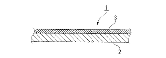
図1及び図2には、本発明による遮水シートの一実施の形態が示されていて、この遮水シート1は、遮水層2と、遮水層2に積層される支持層3と、支持層3に固定される複数の固定片4とから構成されている。
【0016】
遮水層2は、ポリオレフィン系の樹脂からなるシート状をなすものであって、施工箇所に応じた大きさに形成され、この実施の形態においては、幅が2.1m、長さが法面の長さ、厚さが1.5mmに形成されている。
【0017】
ポリオレフィン系の樹脂としては、例えば、ポリエチレン、ポリプロピレン、オレフィン系エラストマー等が挙げられる。具体的には、メタセロン系触媒で重合された低密度ないし中密度ポリエチレン系樹脂を主成分とした樹脂等が挙げられる。
【0018】
支持層3は、織布、不織布等からなるシート状をなすものであって、遮水層2と略同一長さ、遮水層2よりも小幅に形成され、この実施の形態においては、幅が2.0m、長さが法面の長さ、厚さが10mmに形成されている。織布、不織布等としては、例えば、ポリエステル系の合成樹脂繊維が挙げられる。
【0019】
支持層3は、遮水層2の上部中央部に熱融着、接着剤による接着等の手段により一体に接合されるようになっている。この場合、支持層3は、支持層3の幅方向の両端から遮水層2の幅方向の両端部が所定の幅ではみ出るように遮水層2に積層され、遮水層2の支持層3からはみ出た部分が法面13に後述する遮水構造9を施工する際に、法面13の幅方向に隣接する遮水シート1、1同士を接合する重ね代6となるものである。
【0020】
固定片4は、支持層3と同様に、ポリエステル系の合成樹脂からなる帯状をなすものであって、この実施の形態においては、幅が約2.0m(支持層3の幅と同一方向の長さ)、長さが300mm、厚さが10mmに形成されている。
【0021】
固定片4は、支持層3の上部に、支持層3の長さ方向に向かって所定の間隔(この実施の形態においては5m間隔)ごとに、かつ各々が支持層3の幅方向(長さ方向に略直交する方向)を向くように、並行に一または複数個設けられるようになっている。
【0022】
各固定片4は、長さ方向の一端部側(法面13の上方に位置する端部)が全幅に渡って熱融着、接着剤による接着等の手段によって支持層3側に一体に接合され、長さ方向の他端部側が支持層3に対して自由端に構成されている。
【0023】
図3及び図4には、一般廃棄物、産業廃棄物等の廃棄物最終処分場の凹所の一例が示されている。すなわち、この凹所11は、略水平の底面12と、この底面12から斜め上方に延在する法面13とを備えており、底面12及び法面13の表面には所定の厚みでコンクリートが吹き付けられている。法面13は、特に勾配50%(水平方向2単位長さに対して、垂直方向1単位長さである勾配)以上の急勾配である場合、吹き付けコンクリート処理が必要である。
【0024】
そして、このような構成の凹所11の内面に前述した遮水シート1を用いて遮水構造9を施工するには、まず、凹所11の開口周縁部に全周に渡って係止溝14を掘削する。
【0025】
そして、凹所11の敷設位置に遮水シート1を搬送し、遮水シート1の上端部を係止溝14内に位置させ、係止溝14内に土嚢等を挿入して遮水シート1の上端部を仮固定する。この遮水シート1の敷設に際しては、法面13が急勾配、かつ吹きつけコンクリート処理されているため、遮水シート1が滑り易く、該遮水シート上端部の固定部分に力が集中する。従って、当該遮水シート1の上端部を固定(仮固定)する。この状態で遮水シート1を凹所11の法面13に沿って上から下に向かって所定寸法敷き広げつつ下降させる。この場合、図4に2点鎖線で示すように、遮水シート1の下降させる先端を折り返し、支持層3に固定された固定片4を外部に露出させる。
【0026】
そして、遮水シート1の上位に位置する固定片4の自由端側をフラットバー7で押さえた状態で、コンクリート釘等の固定金具8を吹き付けコンクリート処理された法面13に垂直に打ち付けることにより法面13側に固定し、該法面13に遮水シート1を固定する。このようにして、遮水シート1を所定寸法づつ下降させ、下位に位置する固定片4を順次法面13側に固定することにより、該法面13の敷設位置に遮水シート1を固定する。
【0027】
そして、水平方向に隣接する次の敷設位置に遮水シート1を搬送し、前回と同様の方法で遮水シート1の上端部を係止溝14内に固定し、複数の固定片4、4……を法面13側に固定し、法面13の敷設位置に遮水シート1を固定する。
【0028】
この場合、前回の遮水シート1の遮水層2と今回の遮水シート1の遮水層2の幅方向の端部同士が所定の幅(この実施の形態では約100mm)で重なり合うように、今回の遮水シート1の敷設位置を予め調整しておく。
【0029】
なお、遮水シート1を法面13に敷設した後に、図示はしないが、必要に応じて、遮水シート1の上部の複数箇所に土嚢等を配置し、遮水シート1を押さえるようにしても良い。
【0030】
そして、隣接する遮水シート1、1の遮水層2、2の重合部を熱風自走式二重融着機(図示せず)により熱融着し、一体に接合する。この場合、熱風自走式二重融着機の熱風の温度を400〜550℃、速度を1.5〜2.5m/minに設定し、接合作業を行う。なお、熱風自走式二重融着機が使用できない箇所においては、手動式融着機を使用しても良い。
【0031】
そして、遮水層2、2同士を接合した後、加圧試験により接合部の漏れの検査を行う。
【0032】
加圧試験は、図7に示すように、絞め具20を用いて接合部の両端部を密閉し、圧縮空気供給装置21のノズル22を接合部の検査溝内に挿入し、圧縮空気を減圧弁により調整しながら供給する。この場合の圧力は0.05〜0.15MPaとする。そして、基準圧力に達した後に、バルブを絞めて30秒間保持する。加圧による遮水シート1の伸びにより圧力の低下があった場合には保持時間を延長し、圧力低下が収まったことを確認する。そして、漏気の有無を確認し、漏気がなく、圧力の低下率が20パーセント以内を合格とする。
【0033】
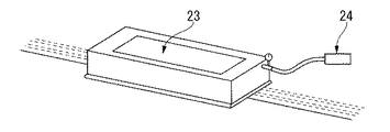
なお、手動式融着機を使用した箇所については、負圧試験により接合部の漏れの検査を行う。すなわち、図8に示すように、接合部に石鹸水を塗布し、検査治具23をセットし、真空ポンプ24により検査治具23内の空気を抜き、負圧条件50mmHg(6700Pa)で引きながら気泡の有無を10秒間観察する。そして、漏気による気泡の発生がなければ合格とする。
【0034】
そして、上記のような遮水シート1の敷設、隣接する遮水シート1、1同士の接合、接合部の漏れの検査を法面13の全体に渡って繰り返し行うことにより、法面13の全体に複数の遮水シート1、1……を敷設する。
最後に、係止溝14内に土のう等で仮固定していた遮水シートを、土のうを取り除きコンクリート等を打設して本固定する。
【0035】
そして、遮水シート1、1……の敷設が終了した後に、遮水シート1、1……の上部に、図5に示すように、ポリエステル系の合成繊維からなるカラー保護マット25の敷設を行う。
【0036】
カラー保護マット25は、遮水シート1と同様に、上端部を係止溝14内に位置し、係止溝14内にコンクリート等を打設して上端部を固定し、この状態で凹所11の法面13に沿って上から下に向かって敷き広げる。
【0037】
そして、隣接するカラー保護マット25、25の幅方向の重合部を手動式融着機又は携帯式バーナーにより熱融着し、一体に接合する。そして、隣接するカラー保護マット25、25の幅方向の端部同士を接合した後に、カラー保護マット25、25……の損傷等の表面状態及び接合部の剥がれ等を目視により検査する。
【0038】
このようにして、遮水シート1、1……の上部にカラー保護マット25、25……を敷設することにより、法面13の全体に遮水シート1、1……とカラー保護マット25、25……とによる遮水構造9を施工することができるものである。
【0039】
なお、凹所11の底面12については、図6に示すように、一般的な遮水構造、すなわち、下層保護マット30(ポリエステル系合成繊維)、遮水シート31(メタロセン触媒低密度ポリエチレン)、中間保護マット32(ポリエステル系合成繊維)、遮水シート33(メタロセン触媒低密度ポリエチレン)、及び上層保護マット34(ポリエステル系合成繊維)からなる遮水構造35とすればよい。
【0040】
上記のように構成したこの実施の形態による遮水シート及び遮水構造並びに社水構造の施工方法にあっては、ポリオレフィン系の樹脂からなる遮水層2に織布、不織布等からなる支持層3を積層し、この支持層3が凹所11の法面13側に位置するように施工するとともに、支持層3に固定した複数の固定片4、4……を固定金具8により法面13側に固定するように構成したので、滑り易い特性を有するポリオレフィン系の樹脂からなる遮水層2であっても、遮水層2の滑りを防止する対策を施す必要はなく、施工に要する手間を少なくすることができる。また、支持層3が不織布である場合には、吹き付けコンクリート処理された法面13に対して滑り難いという利点があり、更に固定片4の固定により遮水シート1の上端部に力が集中することがなく、法面13を階段状に形成する必要がない等の利点がある。
また、織布、不織布等からなる支持層3によってポリオレフィン系の樹脂からなる遮水層2を支持することができるので、温度変化による遮水層2の伸縮量を少なく抑えることができ、遮水層2の耐久性を高めることができる。さらに、ポリオレフィン系の樹脂は重量が軽く、ゴム等に比べて価格が安いので、施工費を大幅に低減させることができる。さらに、長期間風雨に晒されても、劣化するようなことはないので、長期に渡って廃棄物からの有害物質等の流出を防止でき、周囲の環境保護に貢献することができることになる。
なお、上記の実施の形態においては、固定片4を法面13の上下方向に所定の間隔ごとに、かつ法面の上下方向に略直交する方向になるよう支持層3に一または複数個設けられている構成としたが、この構成に代えて、固定片4を法面13の上下方向に所定の間隔ごとに、かつ法面13の略上下方向になるよう支持層3に一または複数個設けられている構成としてもよい。
【0041】
【発明の効果】
以上、説明したように、本発明の遮水シート及び遮水構造並びに遮水構造の施工方法によれば、遮水シートを、ポリオレフィン系の樹脂からなる遮水層と、遮水層に積層される織布、不織布等からなる支持層と、支持層に設けられる一または複数個の固定片とによって構成したので、一または複数個の固定片を法面側に固定することにより、固定片を介して支持層を法面に固定することができるとともに、支持層を介して遮水層を法面に固定することができることになる。従って、滑り易い特性を有するポリオレフィン系の樹脂からなる遮水層であっても、遮水層の滑りを防止する対策を施す必要はなく、施工に要する手間を少なくすることができる。
また、織布、不織布等からなる支持層によってポリオレフィン系の樹脂からなる遮水層は支持されることになるので、温度変化による遮水層の伸縮量を少なく抑えることができ、遮水層の耐久性を大幅に高めることができる。
さらに、ポリオレフィン系の樹脂は重量が軽く、ゴム等に比べて価格が安いので、施工費を大幅に低減させることができる。
さらに、ポリオレフィン系の樹脂は、長期間風雨に晒されても、劣化するようなことはないので、長期に渡って廃棄物からの有害物質等の流出を防止でき、周囲の環境保護に貢献することができることになる。
【図面の簡単な説明】
【図1】本発明による遮水シートの一実施の形態を示した平面図である。
【図2】図1の断面図である。
【図3】本発明による一実施の形態の遮水シートを凹所の法面に敷設した状態を示した説明図である。
【図4】図3のA部の拡大図である。
【図5】本発明による遮水構造の一実施の形態を示した部分拡大断面図であって、法面に施工した状態を示した説明図である。
【図6】本発明による遮水構造の一実施の形態を示した部分拡大断面図であって、底面に施工した状態を示した説明図である。
【図7】漏れ検査の一例を示した説明図である。
【図8】漏れ検査の他の例を示した説明図である。
【符号の説明】
1 遮水シート
2 遮水層
3 支持層
4 固定片
8 固定金具
9 遮水構造
11 凹所
12 底面
13 法面
14 係止溝[0001]
TECHNICAL FIELD OF THE INVENTION
The present invention relates to a seepage control sheet, a seepage control structure, and a method of constructing a seepage control structure, and more particularly to a seepage control method that can be effectively used in a final disposal site for waste such as general waste and industrial waste. The present invention relates to a sheet, a water-blocking structure, and a method of installing a water-blocking structure.
[0002]
[Prior art]
In general, at the final disposal site for general waste and industrial waste, etc., it is necessary to prevent harmful substances etc. from spilling out of the waste stored in the recess and contaminating the surrounding soil and groundwater. For this purpose, a water-blocking sheet is laid on the inner surface of the recess to construct a water-blocking structure to prevent harmful substances from flowing out.
[0003]
Conventionally, a water-blocking sheet made of vinyl chloride has been used for the water-blocking structure of the recess at such a waste final disposal site, but the water-blocking sheet made of vinyl chloride may cause environmental problems. Therefore, in recent years, a waterproof sheet made of polyolefin such as polyethylene and polypropylene has been used instead of a waterproof sheet made of vinyl chloride.
[0004]
Waterproof sheets made of polyolefin do not have any environmental problems as waterproof sheets made of polyvinyl chloride, but they are laid on the slope of the recess because the surface is smooth and slippery. In such a case, measures to prevent slippage are required, and the work is extremely troublesome.
[0005]
Conventionally, as a countermeasure against slippage of the water-impervious sheet, there has been proposed a method in which a slope is formed in a step shape and the water-impervious sheet is fixed at a step portion of the slope. Further, in order to solve the problem of slippage of the water-impervious sheet, a water-impervious structure is also constructed on the slope of the recess using a rubber water-impervious sheet (for example, see Patent Document 1). ).
[0006]
[Patent Document 1]
Japanese Patent No. 2955928
[Problems to be solved by the invention]
However, rubber waterproofing sheets are inferior in durability, and deteriorate in a short period of time when exposed to wind and rain, causing a problem of outflow of harmful substances and the like. Moreover, the construction is troublesome due to the heavy weight, and the construction cost is high due to the high price.
[0008]
The present invention has been made in view of the above-described conventional problems, does not cause environmental problems, requires less labor for construction, and is more inexpensive and has lower construction costs. It is an object of the present invention to provide a water-blocking sheet, a water-blocking structure, and a method of constructing a water-blocking structure, which can reduce the cost.
[0009]
[Means for Solving the Problems]
The present invention employs the following means in order to solve the above problems. That is, the invention according to
According to the impermeable sheet according to the present invention, by fixing the fixing piece to the slope, the support layer is fixed to the slope, and the impermeable layer is fixed to the slope via the support layer. .
[0010]
The invention according to
According to the impermeable sheet according to the present invention, one or a plurality of fixing pieces provided at predetermined intervals in the vertical direction of the slope, and provided in a direction substantially perpendicular to the vertical direction of the slope. By fixing to the slope, the support layer is fixed to the slope, and the impermeable layer is fixed to the slope via the support layer.
[0011]
The invention according to
[0012]
The invention according to
[0013]
The invention according to claim 5 is directed to a recess having a substantially horizontal bottom surface and a sprayed concrete-treated slope surface extending obliquely upward at least 50% from the bottom surface. A water-blocking structure constructed by laying a water-blocking sheet thereon, wherein the water-blocking sheet according to any one of
According to the water-blocking structure according to the present invention, a water-blocking sheet is laid on the slope, and a fixing piece provided on the support layer of the water-blocking sheet is fixed with a fixing bracket such as a concrete nail. By welding the sheets together, the support layer is fixed to the slope, the impermeable layer is fixed to the slope via the support layer, the adjacent impermeable sheets are welded together, and the impermeable sheet is blocked on the slope by the impermeable sheet. Water structure will be constructed.
[0014]
The invention according to
According to the construction method of the water-blocking structure according to the present invention, the water-blocking sheet is spread along the slope, after being fixed to the substantially flat opening peripheral portion at the upper part of the slope, and is provided on the support layer of the water-blocking sheet. The fixing pieces provided are fixed with fixing metal fittings such as concrete nails and laid over the entire length of the slope. This is repeated for a plurality of water-impervious sheets over the entire slope, and the adjacent water-impervious sheets are welded to each other, so that the entire surface of the slope is impermeable to water. The structure will be constructed.
[0015]
BEST MODE FOR CARRYING OUT THE INVENTION
Hereinafter, embodiments of the present invention shown in the drawings will be described.
1 and 2 show one embodiment of a water-blocking sheet according to the present invention. The water-blocking
[0016]
The water-
[0017]
Examples of the polyolefin-based resin include polyethylene, polypropylene, and olefin-based elastomer. Specific examples include a resin mainly composed of a low-density to medium-density polyethylene resin polymerized with a metaceron-based catalyst.
[0018]
The
[0019]
The
[0020]
The fixing
[0021]
The fixing
[0022]
One end of the fixing
[0023]
FIG. 3 and FIG. 4 show an example of a recess at a final disposal site for general waste, industrial waste, and the like. That is, the
[0024]
In order to construct the water-blocking structure 9 on the inner surface of the
[0025]
Then, the water-
[0026]
Then, while fixing the free end side of the fixing
[0027]
Then, the water-
[0028]
In this case, the width direction ends of the water
[0029]
After laying the
[0030]
Then, the superposed portions of the water-blocking
[0031]
Then, after joining the water-
[0032]
In the pressurization test, as shown in FIG. 7, both ends of the joint are sealed using a
[0033]
In addition, about the part which used the manual fusion machine, the leak of a joining part is examined by a negative pressure test. That is, as shown in FIG. 8, soapy water is applied to the joint, the
[0034]
By laying the above-described water-
Finally, the impermeable sheet temporarily fixed in the locking
[0035]
After the laying of the water-
[0036]
The
[0037]
Then, the overlapping portions of the adjacent
[0038]
In this way, by laying the
[0039]
As shown in FIG. 6, the
[0040]
In the method of constructing the water impermeable sheet, the water impermeable structure, and the company water structure according to this embodiment configured as described above, the water
Further, since the water-
In the above embodiment, one or a plurality of fixing
[0041]
【The invention's effect】
As described above, according to the impermeable sheet and impermeable structure and the method of constructing the impermeable structure of the present invention, the impermeable sheet is laminated on the impermeable layer made of polyolefin resin and the impermeable layer. Woven fabric, a support layer made of non-woven fabric, and one or more fixing pieces provided on the support layer, so that one or more fixing pieces are fixed to the side of the slope, thereby fixing the fixing pieces. The support layer can be fixed to the slope through the support, and the impermeable layer can be fixed to the slope through the support. Therefore, even with a water barrier layer made of a polyolefin resin having slippery properties, it is not necessary to take measures to prevent the water barrier layer from slipping, and the labor required for construction can be reduced.
In addition, the water-impervious layer made of a polyolefin resin is supported by the support layer made of a woven fabric, a non-woven fabric, etc. Durability can be greatly increased.
Furthermore, since the polyolefin resin is light in weight and inexpensive as compared with rubber or the like, the construction cost can be significantly reduced.
Furthermore, since the polyolefin resin does not deteriorate even if it is exposed to wind and rain for a long period of time, it is possible to prevent harmful substances from flowing out of the waste for a long period of time and contribute to the protection of the surrounding environment. You can do it.
[Brief description of the drawings]
FIG. 1 is a plan view showing an embodiment of a water impermeable sheet according to the present invention.
FIG. 2 is a sectional view of FIG.
FIG. 3 is an explanatory view showing a state in which a water impermeable sheet according to an embodiment of the present invention is laid on a slope of a recess.
FIG. 4 is an enlarged view of a portion A in FIG. 3;
FIG. 5 is a partially enlarged cross-sectional view showing one embodiment of a water-blocking structure according to the present invention, and is an explanatory view showing a state where the water-blocking structure is installed on a slope.
FIG. 6 is a partially enlarged cross-sectional view showing one embodiment of a water-blocking structure according to the present invention, and is an explanatory view showing a state where the water-blocking structure is installed on a bottom surface.
FIG. 7 is an explanatory diagram showing an example of a leak test.
FIG. 8 is an explanatory diagram showing another example of the leak inspection.
[Explanation of symbols]
REFERENCE SIGNS
Claims (6)
Priority Applications (1)
| Application Number | Priority Date | Filing Date | Title |
|---|---|---|---|
| JP2002374813A JP2004202379A (en) | 2002-12-25 | 2002-12-25 | Water sealing sheet, water sealing structure, and water sealing structure construction method |
Applications Claiming Priority (1)
| Application Number | Priority Date | Filing Date | Title |
|---|---|---|---|
| JP2002374813A JP2004202379A (en) | 2002-12-25 | 2002-12-25 | Water sealing sheet, water sealing structure, and water sealing structure construction method |
Publications (1)
| Publication Number | Publication Date |
|---|---|
| JP2004202379A true JP2004202379A (en) | 2004-07-22 |
Family
ID=32812718
Family Applications (1)
| Application Number | Title | Priority Date | Filing Date |
|---|---|---|---|
| JP2002374813A Pending JP2004202379A (en) | 2002-12-25 | 2002-12-25 | Water sealing sheet, water sealing structure, and water sealing structure construction method |
Country Status (1)
| Country | Link |
|---|---|
| JP (1) | JP2004202379A (en) |
Cited By (1)
| Publication number | Priority date | Publication date | Assignee | Title |
|---|---|---|---|---|
| JP2010284612A (en) * | 2009-06-15 | 2010-12-24 | Taiyo Kogyo Corp | Impervious structure of waste disposal site and its assembling method |
-
2002
- 2002-12-25 JP JP2002374813A patent/JP2004202379A/en active Pending
Cited By (1)
| Publication number | Priority date | Publication date | Assignee | Title |
|---|---|---|---|---|
| JP2010284612A (en) * | 2009-06-15 | 2010-12-24 | Taiyo Kogyo Corp | Impervious structure of waste disposal site and its assembling method |
Similar Documents
| Publication | Publication Date | Title |
|---|---|---|
| JP4108460B2 (en) | Construction method of tunnel still water structure | |
| KR100875893B1 (en) | The waterproof construct method with waterproof-sheet | |
| US10156052B2 (en) | Containment membrane | |
| KR20120020018A (en) | Waterproof sheet having channel type draining guidance sheet and manufacturing apparatus and method the sameof, tunnel waterproof method using the waterproof sheet | |
| JP2004202379A (en) | Water sealing sheet, water sealing structure, and water sealing structure construction method | |
| JP4287011B2 (en) | Impermeable sheet laying structure and impermeable sheet laying method | |
| JP4589344B2 (en) | Seat waterproof structure and waterproof construction method | |
| KR100431533B1 (en) | waterproof structure of concrete tank using polyethylene sheet | |
| JP2011132669A (en) | Structure for repairing tunnel | |
| JP2928171B2 (en) | Mounting structure and mounting method of waterproof sheet for tunnel | |
| KR20040044660A (en) | Joint structure of waterproofing sheet, constructing method thereof and vertical part treatment structure of waterproofing sheet | |
| KR20090107178A (en) | Waterproof structure for tunnel | |
| JP2003154328A (en) | Construction method for applying impervious sheet to wall surface | |
| JP3537383B2 (en) | Impermeable sheet and its laying method | |
| JP2006305414A (en) | Waste disposal site structure | |
| JP3730712B2 (en) | Impervious structure of waste disposal site | |
| KR200261154Y1 (en) | structure for waterproofing of concrets water tank to used polyethylene sheet | |
| JP5081460B2 (en) | Impermeable structure and construction method of impermeable structure | |
| JPH0957227A (en) | Protective structure of impervious sheet | |
| JP5815952B2 (en) | How to lay a waterproof sheet | |
| JPH0480452A (en) | Inspecting method for water-proof sheet and jointing section | |
| JP2801374B2 (en) | Seat and seat connection structure | |
| JP2801375B2 (en) | Seat connecting member, seat and seat connecting structure | |
| JP5691110B2 (en) | Rehabilitation method of existing impermeable sheet | |
| JPH09299899A (en) | Water shielding structure |
Legal Events
| Date | Code | Title | Description |
|---|---|---|---|
| A621 | Written request for application examination |
Free format text: JAPANESE INTERMEDIATE CODE: A621 Effective date: 20051020 |
|
| A977 | Report on retrieval |
Free format text: JAPANESE INTERMEDIATE CODE: A971007 Effective date: 20070810 |
|
| A131 | Notification of reasons for refusal |
Free format text: JAPANESE INTERMEDIATE CODE: A131 Effective date: 20070821 |
|
| A521 | Request for written amendment filed |
Free format text: JAPANESE INTERMEDIATE CODE: A523 Effective date: 20071017 |
|
| A02 | Decision of refusal |
Free format text: JAPANESE INTERMEDIATE CODE: A02 Effective date: 20071218 |
|
| A521 | Request for written amendment filed |
Free format text: JAPANESE INTERMEDIATE CODE: A523 Effective date: 20080215 |
|
| A911 | Transfer to examiner for re-examination before appeal (zenchi) |
Free format text: JAPANESE INTERMEDIATE CODE: A911 Effective date: 20080311 |
|
| A912 | Re-examination (zenchi) completed and case transferred to appeal board |
Free format text: JAPANESE INTERMEDIATE CODE: A912 Effective date: 20080404 |