JP2004202196A - Electromyograph - Google Patents
Electromyograph Download PDFInfo
- Publication number
- JP2004202196A JP2004202196A JP2003142521A JP2003142521A JP2004202196A JP 2004202196 A JP2004202196 A JP 2004202196A JP 2003142521 A JP2003142521 A JP 2003142521A JP 2003142521 A JP2003142521 A JP 2003142521A JP 2004202196 A JP2004202196 A JP 2004202196A
- Authority
- JP
- Japan
- Prior art keywords
- unit
- signal processing
- myoelectric potential
- power
- storage unit
- Prior art date
- Legal status (The legal status is an assumption and is not a legal conclusion. Google has not performed a legal analysis and makes no representation as to the accuracy of the status listed.)
- Granted
Links
Images


Abstract
Description
【0001】
【発明の属する技術分野】
本発明は、生体の筋肉に発生する電位を検出する筋電位計測装置に関するものである。
【0002】
【従来の技術】
従来、携帯型の筋電位計測装置として、一般にホルター型筋電計が知られている。このホルター型筋電計は、筋電計本体を身体の何れかの場所に固定し、筋電計本体とリード線で接続された電極を計測対象の筋肉へ取り付け、筋肉に発生する電位を検出している。
【0003】
また、検出した筋電位から筋肉状態を推定するものとして、検出した筋電位と予め記憶された最大筋電位とから最大筋電比を求め、筋肉の負担の程度をリアルタイムで推測するものがある(例えば、特許文献1参照。)。
【0004】
しかしながら、上記した従来の筋電位計測装置では、信号を伝送するためのリード線やワイヤー線などが必ず存在しており、被測定者にとって配線の取りまわしが煩雑で使いづらく、また微小な生体信号を扱うことを考えた場合、リード線やワイヤー線などの振動や変形に起因する誘導起電力がノイズの成分となり得た。
【0005】
また、複数の筋肉を同時に計測する場合には、リード線やワイヤー線などにより被測定者の身体動作が制限されたり拘束される場合もあった。
【0006】
上記問題点を解決するために、本発明者らは、電極部と、電極部の電位を増幅する増幅部と、増幅部の信号をリアルタイムに処理する信号処理部と、電源部とが一体化された計測演算処理ユニットと、その処理結果をワイヤレスで受信しリアルタイムに表示する表示ユニットとからなる筋電位計測装置を提案している(特願2002−154267)。
【0007】
【特許文献1】
特開昭60−168435号公報
【0008】
【発明が解決しようとする課題】
しかしながら、本発明者らの上記従来の筋電位計測装置では、リード線などにより被測定者の身体動作が制限されたり拘束されたりすることなく筋電位の計測が行えるものの、筋電位の計測を長時間行って、その結果を記録し分析しようとする場合には、計測結果をリアルタイムに表示する表示部は不向きであると共に、複数の筋肉を同時に計測するには、表示部が1つでは対応できなかったり、ワイヤレスでデータを転送する際の通信の混乱を避けるのが困難などの問題があった。
【0009】
本発明は上記問題点に鑑みて為されたものであって、その目的とするところは、筋肉に発生する筋電位を、被測定者の身体動作を妨げることなく簡便に長時間安定して計測でき、その計測結果を記録できる筋電位計測装置を提供することにある。
【0010】
【課題を解決するための手段】
上記目的を達成するために、請求項1の発明は、被測定者の筋肉の2点間の電位差を検出する電極部と、前記電極部の電位を増幅する増幅部と、前記増幅部の信号をリアルタイムに処理して被測定者の筋肉状態を推定する信号処理部と、前記信号処理部で得られたデータを記憶する記憶部と、前記増幅部と前記信号処理部と前記記憶部とを間欠的もしくは連続的に動作させる制御モードを備えた制御部と、前記各部に必要な電力を供給する電源部とを同一の筐体に組み込んだものとした。この発明によれば、被測定者の身体動作を妨げるリード線やワイヤー線がなく取り扱いが簡便であり、リード線やワイヤー線に起因するノイズの発生が低減され信号の安定性も向上する。また、前記制御部が間欠的に動作させる制御モードを備えたことで電力消費を低減させることができ、連続して長時間の計測ができる。さらに、記憶部を備えているので計測結果を記憶部に記録することで、事後に計測結果を参照したり、分析したりできる。
【0011】
請求項2の発明は、請求項1記載の発明において、前記制御部は、前記増幅部と前記信号処理部と前記記憶部とを、全体を通して少なくとも24時間継続して動作させるものとした。この発明によれば、人間の基本的な生活リズムの単位の1つである24時間という期間を継続して動作させることにより、一時的な計測ではわからない筋肉活動の日内変動を捉えることができ、医学的・生理学的に従来にはない価値あるデータを提供できる。
【0012】
請求項3の発明は、請求項1又は2記載の発明において、前記信号処理部は、前記増幅部の信号から所定の単位時間当たりの絶対値積分値もしくは平方自乗平均値を導出し、前記記憶部は、前記所定の単位時間当たりの絶対積分値もしくは平方自乗平均値を記憶するものとした。この発明によれば、前記記憶部が所定の単位時間当たりのデータを記憶していくので、リアルタイムに全てのデータを記憶していくことに比べて、記憶するデータ量を削減でき、前記記憶部に長時間におよぶ測定結果の記憶が可能となる。また、筋肉の収縮レベルによく相関することが一般に知られている筋電位の絶対値積分値もしくは平方自乗平均値を記録していくことで、臨床的価値が高いデータを得ることができる。加えて、事後に絶対値積分値もしくは平方自乗平均値などを導出する手間が省ける。
【0013】
請求項4の発明は、請求項1乃至3の何れか記載の発明において、被測定者の動きにより発電する発電部と、この発電部で生じた電力を一時的に蓄える蓄電部とを前記筐体に組み込み、前記発電部で生じた電力を直接、又は前記蓄電部を介して前記電源部へ供給するものとした。この発明によれば、被測定者の動きにより発電した電力を用いて被測定者の筋肉の状態を計測するので、効率的な電力利用が可能となり、さらに長時間の計測・記録が可能となる。
【0014】
請求項5の発明は、請求項1乃至4の何れか記載の発明において、前記信号処理部で得られたデータの積算を行う積算部と、この積算部で積算された値を表示する表示部とを有するものとした。この発明によれば、長時間におよぶ測定の途中にも、被測定者は積算された値を見てその時点までの筋肉の使用程度を把握でき、運動量のコントロールが可能となる。また、予め目標となる積算値が決められている場合には、その目標値に向けて運動量を増やしたり運動することを努力するようになり、健康増進の動機付けになる。
【0015】
請求項6の発明は、請求項1乃至5の何れか記載の発明において、前記記憶部は、前記筐体に着脱自在な記憶媒体からなるものとした。この発明によれば、前記記憶部を前記筐体から取り外して外部の処理装置と接続することで、より高度な分析を行うことができるようになる。また、長期的な計測結果を外部の処理装置で管理することも可能となる。また、複数の筋肉から得られた情報を外部の処理装置を用いて一元管理し、分析・比較することもできる。
【0016】
請求項7の発明は、請求項1乃至6の何れか記載の発明において、前記筐体内に被測定者の動きを検出する動作検出部を有し、前記制御部は、前記動作検出部が所定の期間被測定者の動きを検出しなければ、前記増幅部と前記信号処理部と前記記憶部との動作を休止させるものとした。この発明によれば、睡眠中や安静座位の状態などほとんど筋肉を使わない場合に、余分な消費電力を削減でき、さらに長時間の計測が可能となる。
【0017】
請求項8の発明は、請求項1乃至7の何れか記載の発明において、前記電極部は、前記筐体から着脱自在なものとした。この発明によれば、前記電極部を筐体から取り外して消毒することや交換することができ、衛生的に使用することができる。
【0018】
【発明の実施の形態】
以下、本発明を実施形態1から実施形態6によって説明する。
【0019】
(実施形態1)
図1に、本実施形態の筋電位計測装置Aの構成をブロック図で示す。
【0020】
本実施形態の筋電位計測装置Aは、被測定者の筋肉の2点間の電位差を検出する電極部1と、電極部1の検出電位差を増幅する増幅部2と、増幅部2の信号をリアルタイムに処理して被測定者の筋肉状態を推定する信号処理部3と、信号処理部3で得られたデータを記憶する記憶部4と、増幅部2と信号処理部3と記憶部4の動作を制御する制御部5と、電池からなる電源部6とから構成される。
【0021】
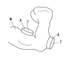
増幅部2と信号処理部3と記憶部4と制御部5と電源部6とは、図2に示す筐体7に内蔵され、電極部1は筐体7の底部外面(人体との接触面)側に一体的に配設され、筐体7は、被測定者Mの例えば腕などに装着される。
【0022】
電極部1は、図3(a)に示すように、2つの筋電位検出電極1aと、グランド電極1bとからなる。筋電位検出電極1aは、被測定者Mの筋肉の2点間の電位差を検出し、グランド電極1bは、その電位差を検出する際の基準電位を得るためのものである。筋電位検出電極1aとグランド電極1bとは、図3(b)に示すように筐体7から着脱自在であり、筐体7から分離させて消毒や電極の交換を行うことができる。
【0023】
増幅部2は、まず電極部1の筋電位検出電極間で発生した電位差を高入力インピーダンスの特性を持つインピーダンス変換手段20により筋電位として安定に取り出す。この高入力インピーダンスの特性により、人体組織を介した電極間の抵抗値が大きくてもその間の電位差を取り出すことが可能で、電解質の糊やペーストを塗布することなく計測ができる。次に、フィルタ手段21が前記筋電位の中からノイズが含まれている周波数成分を除去する。信号が安定しノイズが除去された後に、アンプ手段22で所要の大きさまで筋電位を増幅する。
【0024】
信号処理部3は、マイクロコンピュータで構成されており、被測定者Mの様々な筋肉状態(例えば、発揮筋力や筋疲労状態など)の推定を行う。まず、内蔵のA/D変換機能によって増幅部2で得られた筋電位をA/D変換し、その後プログラムによって実現された各種演算処理機能が施される。本実施形態では演算処理機能として、周波数成分分析を行う高速フーリエ変換(以下、FFTと略す)演算機能と、FFT演算機能で得られた周波数成分のパワースペクトルのうち所要の周波数帯域だけを加算して筋電位の積分値に置き換える積分値導出機能と、予め記憶しておいた最大筋収縮時の積分値との比率から発揮筋力を推定する発揮筋力推定機能と、FFTで得られた前記周波数成分から中心周波数もしくは平均周波数の低下、もしくは高周波数成分の低下を判断して筋疲労の発生を推定する筋疲労検出機能とを有している。
【0025】
信号処理部3で得られた演算結果は、記憶部4に記憶される。記憶部4は、筐体7内に着脱自在に接続されるメモリーカードなどの記憶媒体からなる。記憶部4は、図4に示すように、筐体7から取り外してパソコンPCなどの外部の処理装置と接続することができ、外部の処理装置で前記演算結果を再び読み出すことができる。
【0026】
制御部5は、増幅部2と信号処理部3と記憶部4とを間欠的に動作させて消費電力の低減を図る制御モードを備えており、限られた電池容量の中で、筋電位計測装置Aの長時間使用を可能とする。また、その制御モード以外にも、例えば連続的に計測を行う制御モードなど、多様な制御モードを備えている。
【0027】
電源部6は、増幅部2と信号処理部3と記憶部4と制御部5の動作のために必要な電力を供給する。
【0028】
かかる筋電位計測装置Aにおいては、取り扱いが煩雑なリード線やワイヤー線がなく、筐体7の電極部1側を被測定者Mの測定対象の筋肉上に装着するだけで筋電位の計測およびその計測結果の記録ができるので、被測定者Mの身体動作を制限したり拘束したりすることなく、取り扱いが簡便である。また、リード線やワイヤー線に起因するノイズの発生が低減され信号の安定性も向上する。その際、着衣のままでの計測および記録も可能である。
【0029】
また、同時に複数の筋肉の電位を計測し記録することも容易である。
【0030】
また、制御部5が間欠的に動作を行う制御モードを備えたことにより、限られた電池容量の中で連続して長時間におよぶ使用が可能となり、運動トレーニング中の筋の活性度合いや日常生活時の筋の状態などの記録・分析を行うことができ、これまでに無い臨床医学データが得られ、筋電位計測装置を用いた治療の精度の向上が期待できる。
【0031】
また、記憶部4が筐体7に着脱自在な記憶媒体であるので、計測結果(演算結果)を外部の処理装置に移して長期的にデータを管理することや、筐体7内では困難な高度な分析を行うことも可能となる。また、複数の筋肉から得られる情報を外部の処理装置に一元管理することもできる。
【0032】
また、病院などの医療現場をはじめ、衛生面に注意を払うべきところで利用する場合に皮膚に接触する部分の消毒は欠かせないが、電極部1が筐体7から着脱自在であり電極部1を筐体7から取り外して消毒を行うことができるため、衛生的に使用することができる。電極部1を使い捨ての電極とし、使用するたびに電極部1を交換するようにしてもよい。なお、本実施形態では、電極部1は筋電位検出電極1aとグランド電極1bとを独立して取り外すことができたが、図5に示すように、筋電位検出電極1aとグランド電極1bとを一体化された状態で取り外すようにしてもよい。
【0033】
(実施形態2)
本実施形態における基本構成は実施形態1と共通するために共通する部分については同一の符号を付して説明を省略し、本実施形態の特徴となる部分についてのみ詳細に説明する。
【0034】
則ち本実施形態の筋電位計測装置Bは、実施形態1に対して、制御部5が、前記増幅部と前記信号処理部と前記記憶部とを、全体を通して少なくとも24時間継続して動作させる点に特徴がある。
【0035】
かかる筋電位計測装置Bにおいては、人間の基本的な生活リズムの単位の1つである24時間という期間を継続して動作させることにより、一時的な計測ではわからない筋肉活動の日内変動を捉えることができ、医学的・生理学的に価値のあるデータを提供できる。
【0036】
(実施形態3)
本実施形態における基本構成は実施形態1又は2と共通するために共通する部分については同一の符号を付して説明を省略し、本実施形態の特徴となる部分についてのみ詳細に説明する。
【0037】
則ち本実施形態の筋電位計測装置Cは、実施形態1又は2に対して、図6に示すように動作検出部8を備えた点に特徴がある。
【0038】
動作検出部8は、一般に広く認知されている加速度センサやジャイロなどを用いて、被測定者Mの身体の動きを検出し、被測定者Mの身体の動きがあるか否かを制御部5へと伝達する。
【0039】
制御部5は、動作検出部8が所定の期間被測定者Mの動きを検出しなければ、増幅部2と信号処理部3と記憶部4の動作を休止させる。再び、動作検出部8が被測定者Mの身体の動きを検出すれば、増幅部2と信号処理部3と記憶部4の動作を再開させる。
【0040】
かかる筋電位計測装置Cにおいては、睡眠中や安静座位の状態のようにほとんど筋肉が使用されない場合に、余分な消費電力を低減させることができ、限られた電池容量の中で、長時間の計測が可能となる。
【0041】
(実施形態4)
本実施形態における基本構成は実施形態1と共通するために共通する部分については同一の符号を付して説明を省略し、本実施形態の特徴となる部分についてのみ詳細に説明する。
【0042】
則ち本実施形態の筋電位計測装置Dは、実施形態1に対して、信号処理部3の演算処理機能と、記憶部4に記憶するデータが異なる点に特徴がある。
【0043】
本実施形態の信号処理部3は、演算処理機能として、絶対値積分値導出機能を有している。
【0044】
絶対値積分値導出機能は、増幅部2で得られた筋電位を内臓のA/D変換機能によってA/D変換した後、図7に示すように、所定の単位時間a当たりの筋電位の絶対値化を行い(ステップS1)、絶対値化された筋電位bを加算して(ステップS2)、絶対値積分値cを求める。
【0045】
絶対値積分値導出機能によって求められた絶対値積分値cは、記憶部4に記憶される(ステップS3)。
【0046】
かかる筋電位計測装置Dにおいては、記憶部4が所定の単位時間a当たりのデータを記憶していくので、リアルタイムに全てのデータを記憶していくことに比べて、記憶するデータ量の削減ができ、限られた記憶容量の記憶部4内に長時間におよぶ測定結果の記憶が可能となる。
【0047】
また、絶対値積分値は、筋肉の収縮レベルによく相関することが一般に知られており、絶対値積分値を記録していくことで、臨床的価値が高いデータを得ることができる。
【0048】
尚、信号処理部3は、絶対値積分値導出機能の代わりに、平方自乗平均値(以下、RMS(Root Mean Square)値と略す。)導出機能を有していてもよい。
【0049】
RMS値導出機能は、増幅部2で得られた筋電位を内臓のA/D変換機能によってA/D変換した後、自乗して、自乗された筋電位の自乗値を所定の単位時間内で平均して自乗平均値を求め、さらに自乗平均値を平方演算して、RMS値を求める。
【0050】
この場合、記憶部4は、RMS値導出機能によって求められた所定の単位時間当たりのRMS値を記憶していく。
【0051】
RMS値も絶対値積分値と同様に筋肉の収縮レベルによく相関することが一般に知られており、RMS値を記録していくことで、臨床的価値が高いデータを得ることができる。
【0052】
(実施形態5)
本実施形態における基本構成は実施形態1と共通するために共通する部分については同一の符号を付して説明を省略し、本実施形態の特徴となる部分についてのみ詳細に説明する。
【0053】
則ち、本実施形態の筋電位計測装置Eは、図1に示した筋電位計測装置の構成に加えて、図8に示すように、発電部9と、発電部9で生じた電力を一時的に蓄える蓄電部10とを備え、図2に示した筐体7に夫々内蔵した点に特徴がある。
【0054】
発電部9は、被測定者Mの動き(身体動作)により発電を行う。具体的には、腕時計の自動発電機能で利用されているように、体の振動を磁石の回転運動に変換し、これとコイルを用いて電磁誘導作用により電流を発生させる。
【0055】
発電部9で生じた電力は、直接又は蓄電部10を介して電源部6へ供給される。則ち、被測定者Mが、発電部9が発電するのに十分な大きさの動作を行った場合、発電部9で生じた電力は、直接電源部6へ供給され、電源部6から筋電位計測装置Dの各部へ供給される。また、余剰電力がある場合は、蓄電部10へ蓄電される。逆に、被測定者Mの動作が小さい、或いは動作がない場合には、蓄電部10に蓄電されていた電力が電源部6へ供給される。
【0056】
そもそも、筋電位計測装置は、被測定者Mが何らかの動作を行った際の筋肉の状態を計測するものであり、その動作で発電を行えば、効率的に電力を利用することができる。かかる筋電位計測装置Eにおいては、効率的に電力を利用することで、さらに長時間の計測・記録が可能となる。
【0057】
尚、発電部9と蓄電部10とは、電源部6に含まれた構成でもよい。
【0058】
(実施形態6)
本実施形態における基本構成は実施形態1と共通するために共通する部分については同一の符号を付して説明を省略し、本実施形態の特徴となる部分についてのみ詳細に説明する。
【0059】
則ち、本実施形態の筋電位計測装置Fは、図9に示すように、信号処理部3で得られたデータの積算を行う積算部(図示せず)を筐体7内に有し、この積算部で積算された値を表示する表示部11を筐体7の上面に配置した点に特徴がある。
【0060】
例えば積算部が、信号処理部3で得られたデータとして筋電位の絶対値積分値を測定開始から積算していくとすると、積算された絶対値積分値は、表示部11の、例えば左横に設置された表示ボタン12を押すことで、表示部11にデジタル数字で表示される。表示したい時だけ表示ボタン12を押して表示部11に表示させることで、余分な消費電力を低減している。
【0061】
また、積算部で積算された値は、表示部11の、例えば右横に設置されたクリアボタン13を押すことで、自由にゼロリセットできる。
【0062】
かかる筋電位計測装置Fにおいては、被測定者Mは、長時間におよぶ測定の途中にも、その時点までにどの程度自身の筋肉を使ったかが把握でき、万歩計(R)のように1日の運動量のコントロールが可能となる。また、予め目標となる積算値が決められている場合では、その目標値に向けて運動量を増やしたり運動することを努力するようになり、健康増進の動機付けにもなる。
【0063】
尚、積算部は、信号処理部3の一機能であっても良い。
【0064】
また、本実施形態では、積算部が筋電位の絶対値積分値の積算を行う例をあげたが、絶対値積分値の積算に限定されるものではなく、例えば、筋電位のRMS値の積算を行うものでもよい。
【0065】
【発明の効果】
以上説明したように、本発明では、筋肉に発生する筋電位を、被測定者の身体動作を妨げることなく簡便に長時間安定して計測でき、その計測結果を記録できる。
【図面の簡単な説明】
【図1】実施形態1の筋電位計測装置の構成を示すブロック図である。
【図2】同上の筐体を被測定者の腕に装着した状態を示す図である。
【図3】(a)同上の筐体の外観を示す図である。
(b)同上の筐体から電極部を取り外した図である。
【図4】同上の記憶部を筐体から取り外して外部の処理装置に接続する状態を説明する図である。
【図5】同上の電極部の別の取り外し方を説明する図である。
【図6】実施形態3の筋電位計測装置の構成を示すブロック図である。
【図7】実施形態4の筋電位計測装置の信号処理部の処理の流れを説明する図である。
【図8】実施形態5の筋電位計測装置の構成を示すブロック図である。
【図9】実施形態6の筋電位計測装置を被測定者の太股に装着した状態を示す図である。
【符号の説明】
1 電極部
2 増幅部
3 信号処理部
4 記憶部
5 制御部
6 電源部
7 筐体
8 動作検出部
9 発電部
10 蓄電部
11 表示部
A〜F 筋電位計測装置[0001]
TECHNICAL FIELD OF THE INVENTION
The present invention relates to a myoelectric potential measurement device that detects an electric potential generated in a muscle of a living body.
[0002]
[Prior art]
Conventionally, a Holter-type electromyograph is generally known as a portable electromyogram. This holter-type electromyograph fixes the electromyograph main body to any part of the body, attaches the electrode connected to the electromyograph main body to the measurement target muscle, and detects the potential generated in the muscle. are doing.
[0003]
Further, as a method for estimating a muscle state from a detected myoelectric potential, there is a method for obtaining a maximum myoelectric ratio from a detected myoelectric potential and a previously stored maximum myoelectric potential, and estimating a degree of muscle burden in real time ( For example, see
[0004]
However, in the above-described conventional myoelectric potential measurement device, there are always a lead wire or a wire line for transmitting a signal, and the wiring of the wiring is complicated and difficult to use for a person to be measured. Considering the handling, the induced electromotive force caused by the vibration or deformation of the lead wire or the wire could be a noise component.
[0005]
In the case of simultaneously measuring a plurality of muscles, the body movement of the subject may be limited or restricted by a lead wire or a wire.
[0006]
In order to solve the above problems, the present inventors have integrated an electrode section, an amplification section for amplifying the potential of the electrode section, a signal processing section for processing a signal of the amplification section in real time, and a power supply section. There has been proposed a myoelectric potential measuring device comprising a measured arithmetic processing unit and a display unit for receiving the processing result wirelessly and displaying it in real time (Japanese Patent Application No. 2002-154267).
[0007]
[Patent Document 1]
JP-A-60-168435
[Problems to be solved by the invention]
However, in the above-described conventional myoelectric potential measurement device of the present inventors, although the myoelectric potential can be measured without restricting or restricting the body movement of the subject by a lead wire or the like, measurement of the myoelectric potential is long. If you try to record and analyze the results over time, the display that displays the measurement results in real time is unsuitable, and a single display can handle multiple muscles simultaneously. However, there are problems such as difficulty in avoiding communication disruption when transferring data wirelessly.
[0009]
The present invention has been made in view of the above problems, and an object of the present invention is to easily and stably measure a myoelectric potential generated in a muscle for a long time without disturbing a body movement of a subject. It is an object of the present invention to provide a myoelectric potential measuring device capable of recording the measurement result.
[0010]
[Means for Solving the Problems]
In order to achieve the above object, the invention according to
[0011]
According to a second aspect of the present invention, in the first aspect, the control unit operates the amplifying unit, the signal processing unit, and the storage unit continuously for at least 24 hours throughout. According to the present invention, by continuously operating a period of 24 hours, which is one of the basic human rhythm units, it is possible to capture circadian fluctuations in muscle activity that cannot be determined by temporary measurement. It can provide medically and physiologically valuable data.
[0012]
According to a third aspect of the present invention, in the first or second aspect, the signal processing unit derives an absolute value integrated value or a root mean square value per a predetermined unit time from the signal of the amplifying unit, and stores the signal. The unit stores the absolute integral value or the root mean square value per the predetermined unit time. According to the present invention, since the storage unit stores data per predetermined unit time, the amount of data to be stored can be reduced as compared with storing all data in real time. It is possible to store the measurement result for a long time. In addition, by recording the integrated value of the absolute value of the myoelectric potential or the root mean square value, which is generally known to be well correlated with the contraction level of the muscle, data having high clinical value can be obtained. In addition, it is not necessary to derive an absolute value integrated value or a root mean square value after the fact.
[0013]
According to a fourth aspect of the present invention, in the invention according to any one of the first to third aspects, the power generation unit that generates power by the movement of the subject and a power storage unit that temporarily stores power generated by the power generation unit are provided in the housing. The power generated by the power generation unit is supplied to the power supply unit directly or via the power storage unit. According to the present invention, since the state of the muscle of the subject is measured using the power generated by the movement of the subject, efficient power use becomes possible, and measurement and recording for a longer time become possible. .
[0014]
According to a fifth aspect of the present invention, in the invention according to any one of the first to fourth aspects, an integrating section for integrating the data obtained by the signal processing section, and a display section for displaying a value integrated by the integrating section. And According to the present invention, even during a long measurement, the subject can see the integrated value to grasp the degree of muscle use up to that point, and control the amount of exercise. In addition, when a target integrated value is determined in advance, an effort is made to increase the amount of exercise or exercise toward the target value, which motivates health promotion.
[0015]
According to a sixth aspect of the present invention, in any one of the first to fifth aspects of the invention, the storage section is made of a storage medium that is detachable from the housing. According to the present invention, it is possible to perform more advanced analysis by removing the storage unit from the housing and connecting the storage unit to an external processing device. In addition, long-term measurement results can be managed by an external processing device. Further, information obtained from a plurality of muscles can be centrally managed using an external processing device, and analyzed and compared.
[0016]
According to a seventh aspect of the present invention, in any one of the first to sixth aspects of the present invention, there is provided an operation detecting unit for detecting a movement of the person to be measured in the housing, wherein the control unit determines that the operation detecting unit If the movement of the subject is not detected during the period, the operations of the amplification unit, the signal processing unit, and the storage unit are stopped. According to the present invention, when little muscle is used, such as during sleep or in a sitting position, extra power consumption can be reduced, and measurement can be performed for a longer time.
[0017]
According to an eighth aspect of the present invention, in the first aspect of the present invention, the electrode portion is detachable from the housing. According to this invention, the electrode portion can be disinfected or replaced by removing it from the housing, and can be used in a sanitary manner.
[0018]
BEST MODE FOR CARRYING OUT THE INVENTION
Hereinafter, the present invention will be described with reference to
[0019]
(Embodiment 1)
FIG. 1 is a block diagram showing a configuration of a myoelectric potential measuring device A of the present embodiment.
[0020]
The myoelectric potential measuring device A of the present embodiment includes an
[0021]
The amplifying
[0022]
As shown in FIG. 3A, the
[0023]
The
[0024]
The
[0025]
The calculation result obtained by the
[0026]
The
[0027]
The
[0028]
In such a myoelectric potential measuring device A, there is no complicated lead wire or wire line, and the myoelectric potential can be measured and measured simply by mounting the
[0029]
It is also easy to simultaneously measure and record the potentials of a plurality of muscles.
[0030]
In addition, since the
[0031]
Further, since the
[0032]
In addition, when used in places where attention must be paid to hygiene, such as in medical sites such as hospitals, it is essential to disinfect the parts that come into contact with the skin. Can be disinfected by removing it from the
[0033]
(Embodiment 2)
Since the basic configuration in the present embodiment is common to that of the first embodiment, the same reference numerals are given to the common parts and the description thereof will be omitted, and only the characteristic parts of the present embodiment will be described in detail.
[0034]
That is, in the myoelectric potential measuring device B of the present embodiment, the
[0035]
In such a myoelectric potential measuring device B, by continuously operating for a period of 24 hours, which is one of the basic units of the human life rhythm, it is possible to capture circadian variations in muscle activity that cannot be determined by temporary measurement. And provide medically and physiologically valuable data.
[0036]
(Embodiment 3)
Since the basic configuration in the present embodiment is common to the first or second embodiment, the same reference numerals are given to the same parts and the description thereof will be omitted, and only the characteristic parts of the present embodiment will be described in detail.
[0037]
That is, the myoelectric potential measuring device C of the present embodiment is characterized in that, compared to the first or second embodiment, an operation detecting section 8 is provided as shown in FIG.
[0038]
The motion detection unit 8 detects the movement of the body of the subject M using an acceleration sensor, a gyro, or the like that is widely recognized, and determines whether the body of the subject M is moving or not. Communicate to
[0039]
The
[0040]
In such a myoelectric potential measurement device C, when little muscle is used, such as during sleep or in a sitting position, extra power consumption can be reduced. Measurement becomes possible.
[0041]
(Embodiment 4)
Since the basic configuration in the present embodiment is common to that of the first embodiment, the same reference numerals are given to the common parts and the description thereof will be omitted, and only the characteristic parts of the present embodiment will be described in detail.
[0042]
That is, the myoelectric potential measurement device D of the present embodiment is characterized in that the arithmetic processing function of the
[0043]
The
[0044]
The absolute value integration value deriving function converts the myoelectric potential obtained by the amplifying
[0045]
The absolute value integrated value c obtained by the absolute value integrated value deriving function is stored in the storage unit 4 (Step S3).
[0046]
In such a myoelectric potential measuring device D, since the
[0047]
It is generally known that the absolute value integrated value correlates well with the muscle contraction level, and by recording the absolute value integrated value, data having high clinical value can be obtained.
[0048]
The
[0049]
The RMS value deriving function performs A / D conversion of the myoelectric potential obtained by the amplifying
[0050]
In this case, the
[0051]
It is generally known that the RMS value also correlates well with the muscle contraction level, similarly to the absolute value integration value. By recording the RMS value, data having high clinical value can be obtained.
[0052]
(Embodiment 5)
Since the basic configuration in the present embodiment is common to that of the first embodiment, the same reference numerals are given to the common parts and the description thereof will be omitted, and only the characteristic parts of the present embodiment will be described in detail.
[0053]
That is, in addition to the configuration of the myoelectric potential measurement device shown in FIG. 1, the myoelectric potential measurement device E according to the present embodiment temporarily outputs the power generated by the power generation unit 9 and the power generated by the power generation unit 9 as shown in FIG. The
[0054]
The power generation unit 9 generates power by the movement (body movement) of the subject M. More specifically, as used in an automatic power generation function of a wristwatch, the body vibration is converted into a rotational motion of a magnet, and a current is generated by electromagnetic induction using this and a coil.
[0055]
The power generated by the power generation unit 9 is supplied to the
[0056]
In the first place, the myoelectric potential measuring device measures the state of the muscle when the subject M performs any operation, and if the operation generates electric power, the power can be used efficiently. In such a myoelectric potential measuring device E, by using electric power efficiently, it is possible to perform measurement and recording for a longer time.
[0057]
The power generation unit 9 and the
[0058]
(Embodiment 6)
Since the basic configuration in the present embodiment is common to that of the first embodiment, the same reference numerals are given to the common parts and the description thereof will be omitted, and only the characteristic parts of the present embodiment will be described in detail.
[0059]
That is, as shown in FIG. 9, the myoelectric potential measuring device F of the present embodiment has an integrating unit (not shown) for integrating the data obtained by the
[0060]
For example, assuming that the integrating section integrates the absolute value integrated value of the myoelectric potential as the data obtained by the
[0061]
The value integrated by the integration unit can be freely reset to zero by pressing, for example, a
[0062]
In such a myoelectric potential measuring device F, the subject M can grasp how much his / her muscles have been used up to that point even during the measurement over a long period of time. It is possible to control the daily amount of exercise. In addition, when a target integrated value is determined in advance, an effort is made to increase the amount of exercise or exercise toward the target value, which also motivates health promotion.
[0063]
Note that the integrating section may be a function of the
[0064]
Further, in the present embodiment, an example in which the integrating unit performs integration of the absolute value integrated value of the myoelectric potential has been described. However, the integration is not limited to integration of the absolute value integrated value. May be performed.
[0065]
【The invention's effect】
As described above, according to the present invention, the myoelectric potential generated in the muscle can be easily and stably measured without disturbing the body movement of the subject, and the measurement result can be recorded.
[Brief description of the drawings]
FIG. 1 is a block diagram illustrating a configuration of a myoelectric potential measurement device according to a first embodiment.
FIG. 2 is a diagram showing a state in which the above-described housing is mounted on a subject's arm.
FIG. 3 (a) is a diagram showing an appearance of a housing of the above.
(B) It is the figure which removed the electrode part from the housing same as the above.
FIG. 4 is a diagram illustrating a state in which the storage unit is removed from the housing and connected to an external processing device.
FIG. 5 is a view for explaining another method of removing the electrode part of the above.
FIG. 6 is a block diagram illustrating a configuration of a myoelectric potential measurement device according to a third embodiment.
FIG. 7 is a diagram illustrating a flow of processing of a signal processing unit of a myoelectric potential measurement device according to a fourth embodiment.
FIG. 8 is a block diagram illustrating a configuration of a myoelectric potential measurement device according to a fifth embodiment.
FIG. 9 is a diagram illustrating a state in which the myoelectric potential measurement device according to the sixth embodiment is worn on a thigh of a subject.
[Explanation of symbols]
REFERENCE SIGNS
Claims (8)
Priority Applications (1)
| Application Number | Priority Date | Filing Date | Title |
|---|---|---|---|
| JP2003142521A JP4186702B2 (en) | 2002-10-31 | 2003-05-20 | EMG measurement device |
Applications Claiming Priority (2)
| Application Number | Priority Date | Filing Date | Title |
|---|---|---|---|
| JP2002318919 | 2002-10-31 | ||
| JP2003142521A JP4186702B2 (en) | 2002-10-31 | 2003-05-20 | EMG measurement device |
Publications (2)
| Publication Number | Publication Date |
|---|---|
| JP2004202196A true JP2004202196A (en) | 2004-07-22 |
| JP4186702B2 JP4186702B2 (en) | 2008-11-26 |
Family
ID=32828289
Family Applications (1)
| Application Number | Title | Priority Date | Filing Date |
|---|---|---|---|
| JP2003142521A Expired - Lifetime JP4186702B2 (en) | 2002-10-31 | 2003-05-20 | EMG measurement device |
Country Status (1)
| Country | Link |
|---|---|
| JP (1) | JP4186702B2 (en) |
Cited By (1)
| Publication number | Priority date | Publication date | Assignee | Title |
|---|---|---|---|---|
| JP2017221647A (en) * | 2016-06-10 | 2017-12-21 | パナソニックIpマネジメント株式会社 | Muscle fatigue output device, muscle fatigue output method, and program |
-
2003
- 2003-05-20 JP JP2003142521A patent/JP4186702B2/en not_active Expired - Lifetime
Cited By (1)
| Publication number | Priority date | Publication date | Assignee | Title |
|---|---|---|---|---|
| JP2017221647A (en) * | 2016-06-10 | 2017-12-21 | パナソニックIpマネジメント株式会社 | Muscle fatigue output device, muscle fatigue output method, and program |
Also Published As
| Publication number | Publication date |
|---|---|
| JP4186702B2 (en) | 2008-11-26 |
Similar Documents
| Publication | Publication Date | Title |
|---|---|---|
| Klingeberg et al. | Mobile wearable device for long term monitoring of vital signs | |
| CN101883518B (en) | Apparatus for detection of syncopes | |
| TWI322680B (en) | An ear-type blood-pressure meter and a method of processing in the ear-type blood-pressure meter | |
| JP4342455B2 (en) | Health management device and health management system | |
| US20140073979A1 (en) | eCard ECG Monitor | |
| US20060100533A1 (en) | Apparatus and method for measuring bio signals | |
| KR20190003325A (en) | Self-powered wearable device for continuous biometrics monitoring | |
| US20160051156A1 (en) | Film-type biomedical signal measuring apparatus, blood pressure measuring apparatus using the same, cardiopulmonary fitness estimating apparatus, and personal authentication apparatus | |
| US20090048540A1 (en) | Wearable Health Monitoring Device and Methods for Fall Detection | |
| US20170319082A1 (en) | Phono-Electro-Cardiogram Monitoring Unit | |
| US10631739B2 (en) | Monitoring vital signs | |
| JP2019509151A (en) | Self-supporting EEG recording system | |
| KR20070075515A (en) | Apparatus and method for noninvasive, continuous, and simultaneous measurement of blood pressure and arterial stiffness | |
| KR20210117230A (en) | Apparatus for Inference of sleeping status using Patch type Electrode | |
| WO2016185931A1 (en) | Biological-information measurement device | |
| JP2004503282A (en) | Equipment for measuring and analyzing physical activity | |
| KR102241796B1 (en) | Apparatus for measuring electrocardiogram, and method of operation the apparatus | |
| KR101197435B1 (en) | A portable contactless health monitoring system | |
| KR102171566B1 (en) | Method, apparatus and computer program for measuring biological signals | |
| US9486154B2 (en) | Device and method for recording physiological signal | |
| Yamakoshi | Current status of non-invasive bioinstrumentation for healthcare | |
| JP2001299712A (en) | Long-time biological monitor | |
| JP4186702B2 (en) | EMG measurement device | |
| TWM618094U (en) | Sleep detection device, sleep detection data collection platform and sleep quality analyzation system | |
| CN209018729U (en) | A kind of multi-functional electrocardioscanner |
Legal Events
| Date | Code | Title | Description |
|---|---|---|---|
| A621 | Written request for application examination |
Free format text: JAPANESE INTERMEDIATE CODE: A621 Effective date: 20051114 |
|
| A977 | Report on retrieval |
Free format text: JAPANESE INTERMEDIATE CODE: A971007 Effective date: 20071016 |
|
| A131 | Notification of reasons for refusal |
Free format text: JAPANESE INTERMEDIATE CODE: A131 Effective date: 20071023 |
|
| A521 | Request for written amendment filed |
Free format text: JAPANESE INTERMEDIATE CODE: A523 Effective date: 20071225 |
|
| A131 | Notification of reasons for refusal |
Free format text: JAPANESE INTERMEDIATE CODE: A131 Effective date: 20080520 |
|
| A521 | Request for written amendment filed |
Free format text: JAPANESE INTERMEDIATE CODE: A523 Effective date: 20080722 |
|
| TRDD | Decision of grant or rejection written | ||
| A01 | Written decision to grant a patent or to grant a registration (utility model) |
Free format text: JAPANESE INTERMEDIATE CODE: A01 Effective date: 20080819 |
|
| A01 | Written decision to grant a patent or to grant a registration (utility model) |
Free format text: JAPANESE INTERMEDIATE CODE: A01 |
|
| A61 | First payment of annual fees (during grant procedure) |
Free format text: JAPANESE INTERMEDIATE CODE: A61 Effective date: 20080901 |
|
| FPAY | Renewal fee payment (event date is renewal date of database) |
Free format text: PAYMENT UNTIL: 20110919 Year of fee payment: 3 |
|
| FPAY | Renewal fee payment (event date is renewal date of database) |
Free format text: PAYMENT UNTIL: 20110919 Year of fee payment: 3 |
|
| S533 | Written request for registration of change of name |
Free format text: JAPANESE INTERMEDIATE CODE: R313533 |
|
| FPAY | Renewal fee payment (event date is renewal date of database) |
Free format text: PAYMENT UNTIL: 20110919 Year of fee payment: 3 |
|
| R350 | Written notification of registration of transfer |
Free format text: JAPANESE INTERMEDIATE CODE: R350 |
|
| FPAY | Renewal fee payment (event date is renewal date of database) |
Free format text: PAYMENT UNTIL: 20110919 Year of fee payment: 3 |
|
| FPAY | Renewal fee payment (event date is renewal date of database) |
Free format text: PAYMENT UNTIL: 20120919 Year of fee payment: 4 |