JP2004201392A - Protector for wire harness - Google Patents
Protector for wire harness Download PDFInfo
- Publication number
- JP2004201392A JP2004201392A JP2002365770A JP2002365770A JP2004201392A JP 2004201392 A JP2004201392 A JP 2004201392A JP 2002365770 A JP2002365770 A JP 2002365770A JP 2002365770 A JP2002365770 A JP 2002365770A JP 2004201392 A JP2004201392 A JP 2004201392A
- Authority
- JP
- Japan
- Prior art keywords
- protector
- protector body
- main body
- side walls
- floor
- Prior art date
- Legal status (The legal status is an assumption and is not a legal conclusion. Google has not performed a legal analysis and makes no representation as to the accuracy of the status listed.)
- Pending
Links
Images


Landscapes
- Insertion, Bundling And Securing Of Wires For Electric Apparatuses (AREA)
- Details Of Indoor Wiring (AREA)
Abstract
Description
【0001】
【発明の属する技術分野】
本発明は、ワイヤハーネス用プロテクタに関し、特に、自動車の床下に配策されるワイヤハーネスの電線を保護するためのプロテクタに関するものである。
【0002】
【従来の技術】
従来、電気自動車やハイブリッド自動車等では、車両後部に配置された電池パックと車両前方の電気接続箱等とを接続する太物電線(電線サイズ:8sqあるいは20sq)を、他機器へのノイズの影響を考慮して、床下のフロアパネル(車体パネル)を貫通して車外(床下)に配策することが多い。
この際、上記電線を走行時に跳ね上げられる石や異物等から保護するため、プロテクタを電線に外装して取り付けている。
【0003】
例えば、特開2002−186131号公報に開示されたプロテクタは、図9に示すように、係合孔1aを有する断面逆凹形状の上カバー1と、係止突起2bを有する断面凹形状で底面に複数の開口2aを穿設した下カバー2とからなり、電線Wをプラスチック製のコルゲートチューブCに貫通させた状態で上カバー1と下カバー2の間に横一列に並べて収容している。
上記プロテクタによると、プロテクタ内部に侵入した石等が下カバー2に設けられた開口2aから直ちに排出され、石等による摩耗を防ぐことができる。
【0004】
【特許文献1】
特開2002−186131号公報
【0005】
【発明が解決しようとする課題】
しかしながら、図9に示すプロテクタによると、電線Wを横一列に並べて収容するため、図9に示すように、電線Wが3本程度の場合は問題ないが、電線本数が6本程度に増加した際に、プロテクタが幅広となり設置スペースを大きく取ってしまう問題が発生する。
また、電線Wは太物電線で重量が大きいことが多いので、多数の電線を下カバー2内に一括して収容することとすると、組付作業性を低下させることにも繋がる。
さらに、上記プロテクタでは各電線同士を同じ空間内に収容する構造としているため、コルゲートチューブCを電線Wに外装している部分はよいが、コルゲートチューブCを外装していない部位があると、電線間の短絡防止の確実性が十分でない問題もある。
【0006】
本発明は、上記問題に鑑みてなされたもので、自動車の床下に配策される電線を保護するプロテクタを省スペース化すると共に、車両への組付作業性を向上させ、また、電線間の短絡も確実に防止することを課題としている。
【0007】
【課題を解決するための手段】
上記課題を解決するため、本発明は、車両の床下に配策される電源接続線を含む電線群に外装されるワイヤハーネス用プロテクタであって、
断面凹形状の下層のプロテクタ本体内に電線を挿通した状態で、断面凹形状の上層のプロテクタ本体が上記下層のプロテクタ本体に内嵌され、該上層のプロテクタ本体の両側壁が下層のプロテクタ本体の両側壁の内面に重ねられ、該上層のプロテクタ本体内に電線を挿通させた状態で蓋により閉鎖され、該蓋を上記下層のプロテクタ本体の両側壁に設けられたロック手段で連結固定されることを特徴とするワイヤハーネス用プロテクタを提供している。
【0008】
上記構成とすると、プロテクタ本体を上層と下層に分けて2階建て構造としているので、車両の床下に配策される電線が多数の場合に、プロテクタ自体が幅広とならずに済むので、幅方向に設置領域が確保しにくい場合の省スペース化を図ることができる。
【0009】
上記プロテクタ本体として下層の第1プロテクタ本体と上層の第2プロテクタ本体を設け、上記第1プロテクタ本体の底壁より突出させた電線仕切壁の上端に上記第2プロテクタ本体の底壁を当接させ、この状態で重ねられる第2プロテクタ本体の両側壁を第1プロテクタ本体の両側と同一高さとなる設定としている。
【0010】
上記構成とすると、電線群にプロテクタを組み付ける工程を、第1プロテクタ本体と第2プロテクタ本体とで、別個に分けて行うことができるので、電線が重量のある太物電線である場合の作業負担が軽減され組付作業性を向上させることができる。
また、第1プロテクタ本体の底壁より電線仕切壁を突出させて、各電線を隔離しているので、電線同士の短絡等を確実に防止することができる。
さらに、第1プロテクタ本体の電線仕切壁の上端を第2プロテクタ本体の設置箇所としているので、第1プロテクタ本体に上面を設けずに開口としたままとできるので、電線の収容作業性が損なわれることがない。
【0011】
上記プロテクタは車両床下のワイヤハーネス配策領域において長さ方向の所要箇所で屈曲させ、
車両後部に搭載するバッテリーに接続されてフロアパネルの貫通穴から床下に引き出す電線群に外嵌されて上記貫通穴へ装着されるグロメットと、上記上層のプロテクタ本体の両側壁とを着脱自在に連結させている。
【0012】
上記構成とすると、上記グロメットを上記プロテクタ本体に予め連結しておくことができるので、作業者は、グロメットおよびプロテクタをフロアパネルに固定する際に別々に取り扱わずに済み、グロメットおよびプロテクタのフロアパネルへの組付作業性を向上させることができる。
【0013】
【発明の実施の形態】
本発明の実施形態を図面を参照して説明する。
図1は電気自動車やハイブリッド自動車の床下(フロアパネルの下)に配策されるワイヤハーネスの全体図を示し、電源接続線を含む6本の太物の電線W1〜W6の所要箇所に保護用のコルゲートチューブCを外装し、プロテクタ10、50やグロメット40やクランプ60、61、62等の外装品を取り付けている。
【0014】
プロテクタ10は、下層の第1プロテクタ本体11に電線W4〜W6を挿通し、上層の第2プロテクタ本体12に電線W1〜W3を挿通し、蓋13で閉鎖している。
プロテクタ50は、プロテクタ本体52に電線W1〜W6を挿通し、上面にクリップ部51aを有する蓋51で閉鎖している。
電線W1〜W3の後方側にはフロアパネルPの貫通穴に装着されるグロメット40が取り付けられ、電線W1、W2の後端に高圧バッテリーへ接続される端子80、81が取り付けられていると共に、電線W3の後端には低圧バッテリーへ接続されるコネクタ82が取り付けられている。電線W1〜W3の前方端には電気接続箱等に接続されるコネクタ90〜92が取り付けられている。
【0015】
電線W4〜W6の前方側には上面にロック部63aを有するプロテクタ63が外装されていると共に、前方端にはレバー式コネクタ93が取り付けられており、後方端にはリアモーターへ接続される端子83〜85が取り付けられている。
また、電線W1〜W6を車体に係止するクランプとして、6本の電線W1〜W6をまとめて保持係止すると共に上面にクリップ部60a、61aを有するクランプ60、61と、3本の電線W1〜W3をまとめて保持係止すると共に上面にクリップ部62aを有するクランプ62と、電線W1〜W3を1本ずつ保持係止するバンドクランプ70とを外装している。
【0016】
以下、電線W1〜W6に外装されたプロテクタ10について説明する。
プロテクタ10は、下層の第1プロテクタ本体11と、上層の第2プロテクタ本体12と、蓋13とからなる。
第1プロテクタ本体11は、図2(A)〜(D)に示すように、合成樹脂からなる底壁15と両側壁14とを備えた断面凹形状で、長さ方向の所要箇所で屈曲し、高床部11dと傾斜部11cと低床部11bと垂直部11aとを備えた形状としている。
【0017】
長さ方向に延在する電線仕切壁16を両側壁14の間で等間隔をあけて底壁15より突出し、仕切られた各空間を電線挿通空間S4〜S6としていると共に、電線仕切壁16の高さは、図2(C)に示すように、側壁14の高さの略半分としている。
側壁14の外面の所要箇所には被ロック枠14aが突設されていると共に、側壁14の内面の所要箇所にも被ロック枠14bを突設している。また、側壁14内面の高さ方向の中間位置には後述する第2プロテクタ本体12を仮係止する係止突起14cを突出している。
【0018】
また、高床部11dの側壁14より外方に突出したブラケット19〜21には、ボルト穴19a、20a、21aおよびクリップ部21bを設けていると共に、垂直部11aの垂直方向となった底壁15より外方にボルト穴18aを有するブラケット18を設け、ブラケット18の下面側には底壁15と連続する補強リブ18bを備えている。
【0019】
低床部11bの底壁15には排出溝15aを幅方向に設けていると共に、各電線挿通空間S4〜S6の底壁15にそれぞれ排出孔15bを穿設している。
高床部11dの前端側には、コルゲートチューブCの外面の凹凸と嵌合する凹凸部17を電線仕切壁16と底壁15と両側壁14とに連続して設けており、また、低床部11bと垂直部11aの連続部分でも同様の凹凸部17を設けている。
【0020】
第2プロテクタ本体12は、図3(A)〜(D)に示すように、合成樹脂からなる底壁24と両側壁23とを備えた断面凹形状で、長さ方向の所要箇所で屈曲し、高床部12dと傾斜部12cと低床部12bと垂直部12aとを備えた形状としている。なお、垂直部12aは第1プロテクタ本体11の垂直部11aよりも高背としている。
【0021】
長さ方向に延在する電線仕切壁26を両側壁23の間で等間隔をあけて底壁24より突出し、仕切られた各空間を電線挿通空間S1〜S3としている。電線仕切壁26および両側壁23の高さは、図3(C)に示すように、互いに同一高さであり、かつ、第1プロテクタ本体11の側壁14の高さの略半分の高さとしている。
側壁23の外面には、第1プロテクタ本体11の被ロック枠14bに対応する位置に切欠部23aが設けられていると共に、該切欠部23aの底壁24には被ロック枠14bが挿通可能となる凹部24aを切り欠いている。また、側壁23の外面には、第1プロテクタ本体11の係止突起14cに対応する位置に切欠部23bが設けられていると共に、該切欠部23bの底壁24を被係止部24bとしている。
【0022】
垂直部12aの上端の両側壁23より上方離反方向に一対のアーム部28を突出し、アーム部28の上端面29にボルト穴29aを穿設していると共に、アーム部28の一側面よりクリップ部30aを有するクリップ台座30を突出している。また、垂直部12aの両側壁の上側には被ロック枠23cを設けている。
【0023】
低床部12bの各電線挿通空間S1〜S3の底壁24にそれぞれ排出孔24cを穿設している。高床部12dの先端部25には側壁23を設けておらず、図3(C)に示すように、先端部25の前端の上面側にはコルゲートチューブCの外面の凹凸と嵌合する凹凸部27を電線仕切壁26と底壁24とに連続して設けていると共に、下面側にも円弧状の凹凸部31を3つ設けている。また、低床部12bと垂直部12aの連続部分でも電線仕切壁26と底壁24と両側壁23とに連続する凹凸部31を設けている。
【0024】
蓋13は、図4(A)〜(D)に示すように、合成樹脂からなる上壁33と両側壁32とを備えた断面逆凹形状で、長さ方向の所要箇所で屈曲し、高天部13dと傾斜部13cと低天部13bと垂直部13aとを備えた形状としている。
側壁32は、低背の側壁34と高背の側壁35とを備え、それら所要位置よりロック部34a、35aを突出している。高天部13dの前端側の上壁33の下面には、第2プロテクタ本体12の凹凸部27と対応する位置に円弧状の凹凸部36を設けている。
【0025】
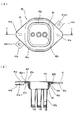
次に、グロメット40について説明する。
グロメット40は、ゴム等の弾性材で一体成形されたグロメット本体42にフランジ状の金属板41を組み付けて形成している。
グロメット本体42は、大径筒部42aと、該大径筒部42aの下端面より連続して突出する3本の小径筒部42bと、大径筒部42aの上端より鍔状に突出したフランジ部42dと、大径筒部42aとフランジ部42dとの連続部の外周面に凹設された環状溝部42c、フランジ部42dの上端面に周状に突出した内シールリップ42eおよび外シールリップ42fと、フランジ部42dの外周下端面に周状に突出した凸部42d−1とを備えている。
【0026】
金属板41は略菱形状で、中央に穿設された開口41dと、該開口41dの外周側に設けられた環状凹部41cと、両端に対向して穿設されたボルト穴41aと、外周端の所要位置より外側下方に突出した断面L字状の一対のクリップ受部41b、クリップ受部41bの中央に穿設された係止孔41b−1とを備えている。
【0027】
そして、金属板41の開口41d周縁をグロメット本体42の環状溝部42cに嵌合係止すると共に、グロメット本体42のフランジ部42dの凸部42d−1を金属板41の環状凹部41cに凹凸嵌合することで、グロメット本体42に金属板41を組み付けている。
【0028】
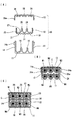
次に、電線W1〜W6へのプロテクタ10およびグロメット40の組付手順について説明する。
図6および図7に示すように、第1プロテクタ本体11の各電線挿通空間S4〜S6にコルゲートチューブCを外装した電線W4〜W6を挿通し、コルゲートチューブCを外装した電線W1〜W3を各電線挿通空間S1〜S3に挿通した第2プロテクタ本体12を上記第1プロテクタ本体11の上から内部に重ねて収容し、第1プロテクタ本体11の係止突起14cを第2プロテクタ本体12の被係止部24bが下方に乗り越えて係止されることで仮保持される。この際、第2プロテクタ本体12の底壁24は、第1プロテクタ本体11の電線仕切壁16の上端に設置されると共に、第2プロテクタ本体12の両側壁23は、第1プロテクタ本体11の両側壁14の内面に重ねられて、該積層状態で同一高さとしている。
下層の電線W4〜W6に外装されたコルゲートチューブCの外面の凹凸を第1プロテクタ本体11の凹凸部17および第2プロテクタ本体12の凹凸部31に嵌合して位置ズレ防止を図っている。
【0029】
図8に示すように、電線W1〜W3はグロメット40の各小径筒部42bに貫通されてその先端をテープ巻き固定されており、第2プロテクタ本体12のクリップ台座30から突出したクリップ部30aをグロメット40のクリップ受部41bの係止孔41b−1に挿入係止することにより、グロメット40を第2プロテクタ本体12に仮固定している。なお、この仮固定状態では、小径筒部42bは下方に向けて第2プロテクタ本体12の各電線挿通空間S1〜S3に配置されており、また、第2プロテクタ本体12のボルト穴29aとグロメット40のボルト穴41aとは合致した状態となっている。
【0030】
次いで、上方より蓋13で閉鎖し該蓋13のロック部34a、35aを第1プロテクタ本体11の被ロック枠14a、14bにロックすると共に、蓋13の垂直部13aに位置するロック部35aは第2プロテクタ本体12の被ロック枠23cにロックする。
なお、図7(C)に示すように、上層の電線W1〜W3に外装されたコルゲートチューブCの外面の凹凸を第2プロテクタ本体12の凹凸部27および蓋13の凹凸部36に嵌合して位置ズレ防止が図られる。
そして、各ブラケット18〜21のボルト穴18a〜21aを通してフロアパネルPにボルト締め固定すると共に、グロメット40に外装された電線W1〜W3をフロアパネルPの貫通穴を通して床下(Y)側から床上(X)側に挿通し、グロメット40および第2プロテクタ本体12の合致したボルト穴41a、29aを通してフロアパネルPにボルト締め固定し、内・外シールリップ42e、42fをフロアパネルPの床下(Y)の下面に押圧している。
【0031】
上記構成とすると、プロテクタ10を上層と下層に分けて2階建て構造にしているので、本実施形態のように床下に配策される電線W1〜W6が6本と多い場合に、プロテクタ10が幅広とならずに済むので、幅方向に設置領域が確保しにくい場合の省スペース化を図ることが可能となる。
また、6本の電線W1〜W6にプロテクタ10を組み付ける工程を、第1プロテクタ本体11と第2プロテクタ本体12とで、別個に分けて行うことができるので、重量のある太物の電線W1〜W6を扱う際の作業負担が軽減される。また、第1プロテクタ本体、第2プロテクタ本体、蓋の3つの部材を互いに固定するために、第1プロテクタ本体と蓋とをロック固定するだけで第2プロテクタ本体を内部に収容することができるので、組付作業性を向上させることが可能となる。
【0032】
さらに、第1プロテクタ本体11および第2プロテクタ本体12の底壁15、24よりそれぞれ電線仕切壁16、26を突出させて、各電線W1〜W6を隔離しているので、電線W1〜W6同士の短絡等を確実に防止することができる。
また、第1プロテクタ本体11の電線仕切壁16の上端を第2プロテクタ本体12の底壁24の設置箇所としているので、第1プロテクタ本体に上面を設けずに開口としたままで第2プロテクタ本体12を内部に収容載置できるので、組付作業性も損なわれることがない。
また、グロメット40を第2プロテクタ本体12にクリップ部30aで予め仮固定しておくことができるので、作業者は、グロメット40およびプロテクタ10をフロアパネルPに固定する際に別々に取り扱わずに済み、グロメット40およびプロテクタ10のフロアパネルPへの組付作業性を向上させることも可能となる。
【0033】
【発明の効果】
以上の説明より明らかなように、本発明によれば、プロテクタ本体を上層と下層に分けて2階建て構造としているので、車両の床下に配策される電線が多数の場合に、プロテクタ自体が幅広とならずに済むので、幅方向に設置領域が確保しにくい場合の省スペース化を図ることができる。
また、電線群にプロテクタを組み付ける工程を、第1プロテクタ本体と第2プロテクタ本体とで、別個に分けて行うことができるので、重量のある電線を扱う場合の作業負担が軽減され組付作業性を向上させることができる。
さらに、第1プロテクタ本体の底壁より電線仕切壁を突出させて、各電線を隔離しているので、電線同士の短絡等を確実に防止することができると共に、第1プロテクタ本体の電線仕切壁の上端を第2プロテクタ本体の設置箇所としているので、第1プロテクタ本体に上面を設けずに開口としたままで第2プロテクタ本体を内部に収容載置できるので、組付作業性も損なわれることがない
【0034】
また、上記グロメットを上記プロテクタ本体に着脱自在に予め仮固定しておくことができるので、作業者は、グロメットおよびプロテクタをフロアパネルに固定する際に別々に取り扱わずに済み、グロメットおよびプロテクタのフロアパネルへの組付作業性を向上させることができる。
【図面の簡単な説明】
【図1】本発明の実施形態のプロテクタの使用状態を示す斜視図である。
【図2】(A)は第1プロテクタ本体の上面図、(B)は側面図、(C)は(B)のC矢視図、(D)は(B)のD矢視図である。
【図3】(A)は第2プロテクタ本体の上面図、(B)は側面図、(C)は(B)のC矢視図、(D)は(B)のD矢視図である。
【図4】(A)は蓋の上面図、(B)は側面図、(C)は(B)のC矢視図、(D)は(B)のD矢視図である。
【図5】(A)はグロメットの下面図、(B)はI−I線断面図である。
【図6】プロテクタの組み付けを示す側面図である。
【図7】(A)はプロテクタの組付前の側面図、(B)は組付後の側面図、(C)は組付後の断面図である。
【図8】グロメットの第2プロテクタ本体への組付状態を示す要部拡大図である。
【図9】従来のプロテクタを示す斜視図である。
【符号の説明】
10 プロテクタ
11 第1プロテクタ本体
12 第2プロテクタ本体
13 蓋
14、23 側壁
16、26 電線仕切壁
17、27 凹凸部
40 グロメット
C コルゲートチューブ
S1〜S6 電線挿通空間
W1〜W6 電線[0001]
TECHNICAL FIELD OF THE INVENTION
The present invention relates to a wire harness protector, and more particularly, to a protector for protecting an electric wire of a wire harness arranged under a floor of an automobile.
[0002]
[Prior art]
2. Description of the Related Art Conventionally, in an electric vehicle, a hybrid vehicle, or the like, a thick electric wire (wire size: 8 sq or 20 sq) connecting a battery pack disposed in a rear portion of a vehicle and an electric junction box or the like in front of the vehicle is affected by noise to other devices. In consideration of the above, it is often arranged outside the vehicle (under the floor) through a floor panel (body panel) under the floor.
At this time, in order to protect the electric wire from rocks, foreign substances, etc., which are flipped up during traveling, a protector is attached to the electric wire.
[0003]
For example, as shown in FIG. 9, a protector disclosed in Japanese Patent Application Laid-Open No. 2002-186131 has an
According to the protector, stones and the like that have entered the inside of the protector are immediately discharged from the opening 2a provided in the
[0004]
[Patent Document 1]
JP-A-2002-186131
[Problems to be solved by the invention]
However, according to the protector shown in FIG. 9, since the electric wires W are housed side by side in a row, there is no problem when the number of the electric wires W is about three as shown in FIG. 9, but the number of the electric wires W is increased to about six. In this case, there is a problem that the protector becomes wide and a large installation space is required.
Further, since the electric wire W is often a thick electric wire and large in weight, if a large number of electric wires are collectively accommodated in the
Further, since the protector has a structure in which the electric wires are housed in the same space, the portion where the corrugated tube C is externally covered with the electric wire W is good. There is also a problem that the reliability of preventing short circuit between them is not sufficient.
[0006]
The present invention has been made in view of the above problems, and in addition to saving space in a protector that protects electric wires routed under the floor of an automobile, improves workability in assembling the vehicle, It is an object to reliably prevent short circuits.
[0007]
[Means for Solving the Problems]
In order to solve the above problems, the present invention is a wire harness protector that is provided on a wire group including a power supply connection line arranged under the floor of a vehicle,
In a state where the electric wire is inserted into the lower protector body having the concave cross section, the upper protector body having the concave cross section is fitted into the lower protector body, and both side walls of the upper protector body have the lower protector body. It is overlapped on the inner surfaces of both side walls, and is closed by a lid in a state where an electric wire is inserted into the upper protector body, and the lid is connected and fixed by locking means provided on both side walls of the lower protector body. The wire harness protector is provided.
[0008]
With the above configuration, the protector body is divided into an upper layer and a lower layer to form a two-story structure. Therefore, in a case where a large number of electric wires are routed under the floor of the vehicle, the protector itself does not need to be wide, so that the width direction can be reduced. When an installation area is difficult to secure, space can be saved.
[0009]
A lower first protector body and an upper second protector body are provided as the protector body, and a bottom wall of the second protector body is brought into contact with an upper end of an electric wire partition wall protruding from a bottom wall of the first protector body. The two side walls of the second protector body stacked in this state are set to have the same height as both sides of the first protector body.
[0010]
With the above configuration, the step of assembling the protector to the wire group can be performed separately for the first protector main body and the second protector main body. Is reduced, and the assembling workability can be improved.
In addition, since the electric wire partition wall is projected from the bottom wall of the first protector body to isolate each electric wire, it is possible to reliably prevent a short circuit between the electric wires.
Further, since the upper end of the wire partition wall of the first protector body is used as the installation location of the second protector body, the first protector body can be left open without providing an upper surface, which impairs the workability of housing the wires. Nothing.
[0011]
The protector is bent at a required position in the length direction in the wiring harness routing area under the vehicle floor,
A grommet that is connected to a battery mounted on the rear of the vehicle and that is fitted to the through-hole through the through-hole of the floor panel and pulled out from the through-hole of the floor panel to the through-hole, and detachably connected to both side walls of the upper-layer protector body Let me.
[0012]
With the above configuration, the grommet can be connected to the protector body in advance, so that the operator does not have to handle the grommet and the protector separately when fixing the grommet and the protector to the floor panel. The workability of assembling to the device can be improved.
[0013]
BEST MODE FOR CARRYING OUT THE INVENTION
An embodiment of the present invention will be described with reference to the drawings.
FIG. 1 shows an overall view of a wire harness routed under a floor (below a floor panel) of an electric vehicle or a hybrid vehicle, which is used to protect six thick electric wires W1 to W6 including a power supply connection line at required positions. Of the corrugated tube C, and exterior parts such as the
[0014]
In the
In the
At the rear side of the electric wires W1 to W3, a
[0015]
A
Also, as clamps for locking the electric wires W1 to W6 to the vehicle body, the
[0016]
Hereinafter, the
The
As shown in FIGS. 2A to 2D, the first protector
[0017]
The
A locked
[0018]
The
[0019]
On the front end side of the
[0020]
As shown in FIGS. 3A to 3D, the
[0021]
An electric
On the outer surface of the
[0022]
A pair of
[0023]
Discharge holes 24c are formed in the
[0024]
As shown in FIGS. 4 (A) to 4 (D), the
The
[0025]
Next, the
The
The grommet
[0026]
The
[0027]
The peripheral edge of the
[0028]
Next, a procedure for assembling the
As shown in FIGS. 6 and 7, the electric wires W4 to W6 with the corrugated tube C are inserted into the electric wire insertion spaces S4 to S6 of the
The unevenness of the outer surface of the corrugated tube C provided on the lower electric wires W4 to W6 is fitted to the
[0029]
As shown in FIG. 8, the electric wires W1 to W3 are penetrated by the respective small-diameter
[0030]
Then, the
In addition, as shown in FIG. 7 (C), the unevenness of the outer surface of the corrugated tube C provided on the upper wires W1 to W3 is fitted into the
Then, the
[0031]
With the above configuration, the
In addition, the step of assembling the
[0032]
Furthermore, since the electric
Further, since the upper end of the electric
Further, since the
[0033]
【The invention's effect】
As is clear from the above description, according to the present invention, the protector body is divided into an upper layer and a lower layer to form a two-story structure. Since it is not necessary to increase the width, it is possible to save space when it is difficult to secure an installation area in the width direction.
In addition, since the process of assembling the protector to the wire group can be performed separately for the first protector body and the second protector body, the work load when handling heavy wires is reduced, and assembly workability is reduced. Can be improved.
Furthermore, since the electric wire partition wall is projected from the bottom wall of the first protector body to isolate each electric wire, a short circuit between the electric wires can be reliably prevented, and the electric wire partition wall of the first protector main body. Since the upper end of the second protector is located at the position where the second protector main body is set, the second protector main body can be housed and placed inside without opening the first protector main body, so that the assembling workability is impaired. There is no [0034]
Further, since the grommet can be temporarily fixed to the protector body in a detachable manner in advance, the operator does not need to handle the grommet and the protector separately when fixing the grommet and the protector to the floor panel. The workability of assembling the panel can be improved.
[Brief description of the drawings]
FIG. 1 is a perspective view showing a use state of a protector according to an embodiment of the present invention.
2A is a top view of a first protector main body, FIG. 2B is a side view, FIG. 2C is a view from arrow C in FIG. 2B, and FIG. 2D is a view from arrow D in FIG. .
3A is a top view of the second protector main body, FIG. 3B is a side view, FIG. 3C is a view from arrow C in FIG. 3B, and FIG. 3D is a view from arrow D in FIG. .
4A is a top view of the lid, FIG. 4B is a side view, FIG. 4C is a view from arrow C in FIG. 4B, and FIG. 4D is a view from arrow D in FIG.
FIG. 5A is a bottom view of the grommet, and FIG. 5B is a cross-sectional view taken along line II.
FIG. 6 is a side view showing assembling of the protector.
FIG. 7A is a side view before assembling the protector, FIG. 7B is a side view after assembling, and FIG. 7C is a sectional view after assembling.
FIG. 8 is an enlarged view of a main part showing a state where the grommet is assembled to the second protector body.
FIG. 9 is a perspective view showing a conventional protector.
[Explanation of symbols]
DESCRIPTION OF
Claims (3)
断面凹形状の下層のプロテクタ本体内に電線を挿通した状態で、断面凹形状の上層のプロテクタ本体が上記下層のプロテクタ本体に内嵌され、該上層のプロテクタ本体の両側壁が下層のプロテクタ本体の両側壁の内面に重ねられ、該上層のプロテクタ本体内に電線を挿通させた状態で蓋により閉鎖され、該蓋を上記下層のプロテクタ本体の両側壁に設けられたロック手段で連結固定されることを特徴とするワイヤハーネス用プロテクタ。A wire harness protector that is exteriorly covered with a wire group including a power supply connection line arranged under a floor of a vehicle,
In a state where the electric wire is inserted into the lower protector body having the concave cross section, the upper protector body having the concave cross section is fitted into the lower protector body, and both side walls of the upper protector body have the lower protector body. It is overlapped on the inner surfaces of both side walls, and is closed by a lid in a state where an electric wire is inserted into the upper protector body, and the lid is connected and fixed by locking means provided on both side walls of the lower protector body. A wire harness protector characterized by the following.
車両後部に搭載するバッテリーに接続されてフロアパネルの貫通穴から床下に引き出す電線群に外嵌されて上記貫通穴へ装着されるグロメットと、上記上層のプロテクタ本体の両側壁とを着脱自在に連結させている請求項1または請求項2に記載のワイヤハーネス用プロテクタ。The protector is bent at a required position in the length direction in the wiring harness routing area under the vehicle floor,
A grommet that is connected to a battery mounted on the rear of the vehicle and that is fitted to the through-hole through the through-hole of the floor panel and pulled out from the through-hole of the floor panel to the through-hole, and detachably connected to both side walls of the upper-layer protector body The wire harness protector according to claim 1 or 2, wherein the wire harness protector is provided.
Priority Applications (1)
| Application Number | Priority Date | Filing Date | Title |
|---|---|---|---|
| JP2002365770A JP2004201392A (en) | 2002-12-17 | 2002-12-17 | Protector for wire harness |
Applications Claiming Priority (1)
| Application Number | Priority Date | Filing Date | Title |
|---|---|---|---|
| JP2002365770A JP2004201392A (en) | 2002-12-17 | 2002-12-17 | Protector for wire harness |
Publications (1)
| Publication Number | Publication Date |
|---|---|
| JP2004201392A true JP2004201392A (en) | 2004-07-15 |
Family
ID=32763228
Family Applications (1)
| Application Number | Title | Priority Date | Filing Date |
|---|---|---|---|
| JP2002365770A Pending JP2004201392A (en) | 2002-12-17 | 2002-12-17 | Protector for wire harness |
Country Status (1)
| Country | Link |
|---|---|
| JP (1) | JP2004201392A (en) |
Cited By (2)
| Publication number | Priority date | Publication date | Assignee | Title |
|---|---|---|---|---|
| CN103094862A (en) * | 2011-11-07 | 2013-05-08 | 北汽福田汽车股份有限公司 | Wiring harness appearance limiting device |
| JP2013212005A (en) * | 2012-03-30 | 2013-10-10 | Sumitomo Wiring Syst Ltd | Wire harness and manufacturing method of the same |
-
2002
- 2002-12-17 JP JP2002365770A patent/JP2004201392A/en active Pending
Cited By (2)
| Publication number | Priority date | Publication date | Assignee | Title |
|---|---|---|---|---|
| CN103094862A (en) * | 2011-11-07 | 2013-05-08 | 北汽福田汽车股份有限公司 | Wiring harness appearance limiting device |
| JP2013212005A (en) * | 2012-03-30 | 2013-10-10 | Sumitomo Wiring Syst Ltd | Wire harness and manufacturing method of the same |
Similar Documents
| Publication | Publication Date | Title |
|---|---|---|
| JP4123986B2 (en) | Wiring harness wiring structure | |
| US5866276A (en) | Battery structure for electric vehicle | |
| US9124079B2 (en) | Electric junction box | |
| US10608385B2 (en) | Connector structure and electric vehicle | |
| US8998644B2 (en) | Connector holder | |
| JP2002225648A (en) | Wire harness protector and wire harness mounting method and structure using the same | |
| JP3284850B2 (en) | Battery mounting structure for electric vehicles | |
| US20120235471A1 (en) | High-voltage cable routing structure for electrically driven vehicle | |
| JP2018156907A (en) | Battery wiring module | |
| EP2838763B1 (en) | Wiring harness | |
| US9758112B2 (en) | Wire harness | |
| JP2000344026A (en) | Wire and tubular part laying structure of electric automobile | |
| JP2004201393A (en) | Protector for wire harness | |
| JP2004201392A (en) | Protector for wire harness | |
| WO2020137613A1 (en) | In-vehicle mounting structure for power storage device | |
| JP2002135941A (en) | Protector for wire harness | |
| JP4600364B2 (en) | Power distribution structure | |
| JP3334621B2 (en) | Electrical junction box and outlet | |
| JP3107139B2 (en) | Wiring box | |
| JP2002044825A (en) | Protector for wire harness and wire harness routing method using the same | |
| JP2003009346A (en) | Mounting structure for electrical junction box | |
| JP3832308B2 (en) | Dust and waterproof cases for vehicles | |
| US20240153677A1 (en) | Grommet unit and wire harness | |
| WO2022202906A1 (en) | Wire harness | |
| JP3454470B2 (en) | Electrical junction box |
Legal Events
| Date | Code | Title | Description |
|---|---|---|---|
| A621 | Written request for application examination |
Free format text: JAPANESE INTERMEDIATE CODE: A621 Effective date: 20041222 |
|
| A977 | Report on retrieval |
Free format text: JAPANESE INTERMEDIATE CODE: A971007 Effective date: 20060210 |
|
| A131 | Notification of reasons for refusal |
Free format text: JAPANESE INTERMEDIATE CODE: A131 Effective date: 20060404 |
|
| A521 | Written amendment |
Free format text: JAPANESE INTERMEDIATE CODE: A523 Effective date: 20060602 |
|
| A02 | Decision of refusal |
Free format text: JAPANESE INTERMEDIATE CODE: A02 Effective date: 20070116 |