JP2004201037A - Method, device, and system for transmitting data - Google Patents
Method, device, and system for transmitting data Download PDFInfo
- Publication number
- JP2004201037A JP2004201037A JP2002367287A JP2002367287A JP2004201037A JP 2004201037 A JP2004201037 A JP 2004201037A JP 2002367287 A JP2002367287 A JP 2002367287A JP 2002367287 A JP2002367287 A JP 2002367287A JP 2004201037 A JP2004201037 A JP 2004201037A
- Authority
- JP
- Japan
- Prior art keywords
- data
- transmission
- multilink
- transmission device
- amount
- Prior art date
- Legal status (The legal status is an assumption and is not a legal conclusion. Google has not performed a legal analysis and makes no representation as to the accuracy of the status listed.)
- Granted
Links
Images


Classifications
-
- H—ELECTRICITY
- H04—ELECTRIC COMMUNICATION TECHNIQUE
- H04L—TRANSMISSION OF DIGITAL INFORMATION, e.g. TELEGRAPHIC COMMUNICATION
- H04L25/00—Baseband systems
- H04L25/02—Details ; arrangements for supplying electrical power along data transmission lines
- H04L25/14—Channel dividing arrangements, i.e. in which a single bit stream is divided between several baseband channels and reassembled at the receiver
Landscapes
- Engineering & Computer Science (AREA)
- Power Engineering (AREA)
- Computer Networks & Wireless Communication (AREA)
- Signal Processing (AREA)
- Time-Division Multiplex Systems (AREA)
- Communication Control (AREA)
Abstract
Description
【0001】
【発明の属する技術分野】
本発明は、データ伝送方法、データ伝送装置およびデータ伝送システムに関する。
【0002】
【従来の技術】
従来より、テレビ電話等のリアルタイム映像通信方式として、ITU−T(国際電気通信連合−電気通信標準化部門)で標準化されたH.32xシリーズが知られている。この方式は、入力された複数のデータ、例えば映像データや音声データを、一つのデータに結合して通信を行うものである。また、このH.32xシリーズにおいては、様々な拡張モデルが規定されており、そのうちの一つであるH.324 AnnexHにおいては、複数の回線(チャネル)を利用して一つのデータを伝送するマルチリンク通信について規定されている。このH.324 AnnexHに関する技術は、例えば、非特許文献1に開示されている。
【0003】
図11を参照して、H.324 AnnexHを採用して映像・音声データの処理を行うための機能構成を説明する。映像符号化部J1は、入力映像をMPEG4等の映像符号化方式を用いて符号化する。音声符号化部J2は、入力音声をAMR等の音声符号化方式を用いて符号化する。通信制御部J3は、H.245で規定されたメッセージを用いて、通信機器同士の能力交換等の通信システムにおける制御を行う。多重化部J4は、H223方式による多重化処理を採用し、映像・音声データを1つの多重化データに変換するモバイルマルチリンク部J5は、変換された多重化データに対して、AnnexHによるマルチリンク処理を施し、多重化データを複数に分割する。
【0004】
次に、図2を参照して、モバイルマルチリンク部J5におけるマルチリンク処理の手順を説明する。まず、多重化データD1をSS(Sampling Size)バイト単位に分割し、伝送する回線用のバッファに順次振り分ける。SSバイトのデータがSPF(Sample Per Frame)個たまった時点で、それらのデータに対して同期フラグF、ヘッダ情報Hおよびヘッダ情報のCRC情報を付与してマルチリンクフレームMFを生成するとともに、このマルチリンクフレームMFを他の端末に伝送する。また、図3に示すように、ヘッダ情報Hには、フルヘッダ情報H1と圧縮ヘッダ情報H2とがある。これらのヘッダ情報Hには、マルチリンクフレームを伝送する回線の番号(CT)、マルチリンク通信用の伝送回線として使用される回線のうちCT値の最も大きい回線により当該マルチリンクフレームが伝送されることを示すフラグ(L)、マルチリンクフレームを伝送する順番を示す番号(SN)、マルチリンクフレームの種類を示すフラグ(FT)が含まれる。また、フルヘッダ情報H1には、さらに、SSおよびSPFの大きさが含まれる。
【0005】
また、モバイルマルチリンク部J5において行われる分割したデータの復元処理の手順について説明する。まず、各回線ごとに同期フラグを検索し、同期フラグが検出された場合には、その直後にあるヘッダ情報のSNとLを参照する。このとき各回線のSNが同じであれば、そのマルチリンクフレームは同じタイミングで伝送されたデータであると判断できる。また、Lのフラグが“ON”状態であれば、その回線が最終の回線であることがわかる。このようにして、各回線から伝送されたデータの同期をとり、各回線により分割して伝送された多重化データを元の多重化データに復元することができる。なお、SNは0から7までの値しか取れないため、伝送遅延の大きさによっては同期がとれないこともある。このため、SSやSPFの値は通信環境や受信側のバッファサイズを考慮にいれて設定される。また、元の多重化データに復元された後は、H.223方式に従って、映像データ、音声データおよびH.245の各データに分割され、それぞれ復号される。そして、復号された各データを同時に再生することにより、リアルタイムの映像通信が可能となる。
【0006】
ところで、上述したH.324 AnnexHにおけるマルチリンク通信では、各回線ごとに分割して送信する複数のデータ(映像データ,音声データ等)を、マルチリンクフレームに格納して送信している。ここで、マルチリンクフレームは、上述したようにヘッダ情報に含まれるSSおよびSPFの値によって格納されるデータ量が決まる。そして、このSSおよびSPFの値は、伝送効率を向上させるために、回線の伝送状況等、様々な要因の変化に応じて変更させることが望ましい。例えば、バースト的な誤りが発生しやすい場合には、SSの値を小さくすることによってバースト誤りによる影響を低減させることができる。また、回線に遅延が発生している場合には、SS×SPF(ペイロード)の値を大きくすることによって遅延許容量を増加させることができる。
【0007】
【非特許文献1】
「ITU-T Recommendation on CD-ROM」,Disc-2,T-REC-H.324-200011-I!AnnH!MSW-E.zip,2000年11月(zipファイル)2000年3月(CD-ROM)
【発明が解決しようとする課題】
しかしながら、上述したマルチリンク通信においてSSおよびSPFの値を変更させるためには、マルチリンクフレームのヘッダ情報に、設定したいSSおよびSPFの値示す情報を付加する必要がある。このため、ペイロードの大きさや、SSおよびSPFの内容を回線の伝送状況に応じて頻繁に変更するような場合には、ヘッダ情報にSSおよびSPFの値が付加される分だけ回線の伝送効率が低下してしまうという問題があった。また、ペイロードの大きさや、SSおよびSPFの内容を変更する場合には、通常使用されている同期フラグとは異なる同期フラグを用いるとともに、送信側と受信側の双方において変更内容を確認するためのやり取りを行う必要がある。このため、煩雑な処理が必要となり、処理負荷が増大してしまうという問題があった。
【0008】
そこで、本発明は、上述した課題を解決するために、マルチリンク通信における回線の伝送効率を向上させるとともに処理負荷を軽減させることができるデータ伝送方法、データ伝送装置およびデータ伝送システムを提供することを目的とする。
【0009】
【課題を解決するための手段】
本発明のデータ伝送方法は、送信側の端末で、送信の対象となるデータを分割し、当該分割したデータを複数の伝送路に振り分けて、所定のデータ量ごとに送信するとともに、受信側の端末で、前記複数の伝送路に振り分けて送信されたデータを受信し、当該受信したデータを結合するデータ伝送方法であって、伝送路ごとの伝送実績に基づいて、データ量とデータの分割パターンの両方または一方を制御することを特徴とする。
【0010】
また、本発明のデータ伝送装置は、送信の対象となるデータを分割する分割手段と、分割手段により分割されたデータを複数の伝送路に振り分けて所定のデータ量ごとに、外部にある端末に送信する送信手段と、外部にある端末から複数の伝送路に振り分けて送信されたデータを受信する受信手段と、受信手段により受信されたデータを結合する結合手段と、結合されたデータに基づいて、伝送路ごとの伝送実績を判定する判定手段と、判定手段による判定に基づいて、データ量とデータの分割パターンの両方または一方を制御する制御手段とを備えることを特徴とする。
【0011】
また、本発明のデータ伝送システムは、第1のデータ伝送装置と第2のデータ伝送装置との間でデータを送受信するデータ伝送システムであって、第1のデータ伝送装置は、送信の対象となるデータを分割する分割手段と、分割手段により分割されたデータを複数の伝送路に振り分けて所定のデータ量ごとに、外部にある端末に送信する送信手段とを備え、第2のデータ伝送装置は、外部にある端末から複数の伝送路に振り分けて送信されたデータを受信する受信手段と、受信手段により受信されたデータを結合する結合手段と、結合されたデータに基づいて、伝送路ごとの伝送実績を判定する判定手段と、判定手段による判定に基づいて、データ量とデータの分割パターンの両方または一方を制御する制御手段とを備えることを特徴とするデータ伝送システム。
【0012】
これらの発明によれば、伝送路ごとの伝送実績に基づいて、データ量とデータの分割パターンの両方または一方を制御することができるため、伝送路の伝送実績に変化が生じた場合には、変化後の伝送実績に基づいてデータ量とデータの分割パターンの両方または一方を制御することができ、ひいてはマルチリンク通信における回線の伝送効率を向上させるとともに処理負荷を軽減させることができる。
【0013】
本発明のデータ伝送方法において、伝送実績は、複数の伝送路として使用されている伝送路数であることが好ましい。
【0014】
この発明によれば、複数の伝送路として使用されている伝送路数に基づいて、データ量とデータの分割パターンの両方または一方を制御することができるため、伝送路数に変化が生じた場合には、変化後の伝送路数に基づいてデータ量とデータの分割パターンの両方または一方を制御することができ、ひいてはマルチリンク通信における回線の伝送効率を向上させるとともに処理負荷を軽減させることができる。
【0015】
本発明のデータ伝送方法において、前述した制御は、伝送路に伝送される伝送データの量に基づいてデータ量とデータの分割パターンの両方または一方を変更する時期を制御することが好ましい。
【0016】
この発明によれば、伝送路に伝送されるデータ量に基づいてデータ量とデータの分割パターンの両方または一方を変更する時期が制御されるため、各伝送路間に遅延が生じた場合でも確実にデータ量とデータの分割パターンの両方または一方を変更することができる。
【0017】
本発明のデータ伝送方法において、前述した制御は、伝送実績に対応して予め規定されるデータ量とデータの分割パターンの両方または一方を参照することにより、データ量とデータの分割パターンの両方または一方を制御することが好ましい。また、本発明のデータ伝送装置において、制御手段は、伝送実績に対応して予め規定されるデータ量とデータの分割パターンの両方または一方を参照することにより、データ量とデータの分割パターンの両方または一方を制御することが好ましい。さらに、本発明のデータ伝送システムにおいて、制御手段は、伝送実績に対応して予め規定されるデータ量とデータの分割パターンの両方または一方を参照することにより、データ量とデータの分割パターンの両方または一方を制御することが好ましい。
【0018】
これらの発明によれば、伝送実績に対応して予め規定されるデータ量とデータの分割パターンの両方または一方を参照することにより、データ量とデータの分割パターンの両方または一方を制御することができるため、伝送路に伝送されるデータ自体にデータ量を示す情報を格納する必要がなくなり、その分マルチリンク通信における回線の伝送効率を向上させることができる。さらに、予め規定されるデータ量とデータの分割パターンの両方または一方から、伝送回線数の変化に応じたデータ量とデータの分割パターンの両方または一方を参照することで、容易にデータ量とデータの分割パターンの両方または一方を変更させることができ、処理負荷を軽減させることができる。
【0019】
本発明のデータ伝送方法において、前述した予め規定されるデータ量とデータの分割パターンの両方または一方は、送信側の端末あるいは受信側の端末のいずれか一方の端末におけるデータのバッファ容量に基づいて定められることが好ましい。
【0020】
この発明によれば、伝送路に伝送されるデータ量を一方の端末におけるバッファ容量に基づいて定めることができるため、マルチリンク通信におけるデータ伝送を端末側のバッファ容量を考慮して定められたデータ量により行うことができる。
【0021】
本発明のデータ伝送方法において、前述した予め規定されるデータ量とデータの分割パターンの両方または一方は、一方の端末から他方の端末に通知されることが好ましく、さらに、通知を受けた他方の端末が、当該通知に対する応答を一方の端末に対して通知することが好ましい。
【0022】
この発明によれば、マルチリンク通信におけるデータ伝送を双方の端末側のバッファ容量を考慮して定められたデータ量により行うことができるため、より確実にデータを伝送することができる。
【0023】
【発明の実施の形態】
以下、本発明に係る装置の各実施形態を図面に基づき説明する。なお、各図において、同一要素には同一符号を付して重複する説明を省略する。
【0024】
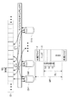
まず、本発明の実施形態について説明する。図1は、本実施形態におけるデータ伝送装置1の機能構成を例示する図である。図1に示すように、データ伝送装置1は、データ入出力部11と、多重部12Aと、分離部12Bと、マルチリンクフレーム構成部13Aと、マルチリンクフレーム復号部13Bと、判定部14と、回線入出力部15とを有する。このようなデータ伝送装置1としては、例えば、テレビ会議システムやテレビ電話システム等に用いられるマルチメディア通信用端末がある。また、本実施形態におけるデータ伝送装置1は、ITU-Tにおいて標準化されたH.324 AnnexHを採用している。
【0025】
データ入出力部11は、映像符号化部11Aaと、映像復号部11Abと、音声符号化部11Baと、音声復号部11Bbと、通信制御部11Cとを有している。映像符号化部11Aaは、映像符号化方式としてITU-TのH.263またはISO/IECのMPEG(Moving a Picture Experts Group)-4を採用しており、データ伝送装置1に入力された映像データをMPEG-4により符号化する。映像復号部11Abは、映像符号化方式としてITU-TのH.263または、ISO/IECのMPEG-4を採用しており、データ伝送装置1から出力される映像データをMPEG-4 により復号化する。音声符号化部11Baは、音声符号化方式としてITU-TのG.723.1またはAMR(Adaptive Multi-Rate)を採用しており、データ伝送装置1に入力された音声データをAMRにより符号化する。音声復号部11Bbは、音声符号化方式としてITU-TのG.723.1またはAMRを採用しており、データ伝送装置1から出力される音声データをAMRにより復号化する。このように復号化された映像データおよび音声データを同時に再生することにより,リアルタイムの映像通信が可能となる。
【0026】
通信制御部11Cは、H245処理部11CAと、SRP処理部11CBとを有している。H245処理部11CAは、ITU-TのH.245を採用しており、例えば、回線の割り当て処理やメッセージの交換処理等、他のデータ伝送装置1との間で行われるマルチメディア通信に関する各種の処理を行う。SRP処理部11CBは、ITU-TのH.324で規定されている再送手順プロトコルであるSRP(Simple Retransmission Protocol)を採用しており、NSRP(Numbered SRP)やCCSRL(Control Channel Segmentation and Reassembly Layer)手順を用いて伝送エラー時におけるデータの再送処理を行う。
【0027】
多重部12Aは、ITU-TのH.223(H.223 AnnexA,H.223 AnnexBでもよい)を採用しており、データ入出力部11において符号化された映像データや音声データ等を一つのデータに多重化して多重化データを生成するとともに、生成した多重化データをマルチリンクフレーム構成部13Aに送信する。また、分離部12Bは、ITU-TのH.223(H.223 AnnexA,H.223 AnnexBでもよい)を採用しており、マルチリンクフレーム復号部13Bにおいて結合された多重化データを映像データや音声データ等に分離するとともに、分離した映像データや音声データ等をデータ入出力部11に送信する。
【0028】
マルチリンクフレーム構成部13Aは、ITU-TのH.324 AnnexHを採用しており、多重部12Aにおいて多重化された多重化データを、マルチリンク通信により通信可能な回線の数に応じて分割する(分割処理)。また、マルチリンクフレーム復号部13Bは、複数の回線を介して他のデータ伝送装置から受信したデータを1つのデータに結合して多重化データを復元する(結合処理)。
【0029】
ここで、図2を参照して上述したマルチリンクフレーム構成部13Aの分割処理について説明する。まず、マルチリンクフレーム構成部13Aは、多重部12Aにおいて多重化されたデータD1をSS(Sampling Size)バイト単位に分割する。次に、マルチリンクフレーム構成部13Aは、SS(Sampling Size)バイト単位に分割したデータを、複数の伝送回線CH1〜CHn(nは8以下の正の整数)に順次振り分ける。マルチリンクフレーム構成部13Aは、各伝送回線CH1〜CHnに振り分けたSSバイトのデータが、SPF(Sample Per Frame)個になった時点で、当該伝送回線に振り分けたSPF個のデータ(SSバイト)を一組(以下、ペイロードPLという。)にする。そして、マルチリンクフレーム構成部13Aは、当該ペイロードPLに対応する同期フラグFやヘッダ情報Hを付与して、一つのマルチリンクフレームMFを生成する。つまり、マルチリンクフレームMFには、同期フラグF、ヘッダ情報H、およびSSバイト×SPF個からなるペイロードPLが含まれる。マルチリンクフレーム構成部13Aは、生成したマルチリンクフレームMFを、当該マルチリンクフレームMFに対応する伝送回線を介して他のデータ伝送装置に送信する。このような分割処理を行うことにより、1つの多重化データを複数の伝送回線に分割して伝送することが可能になる。
【0030】
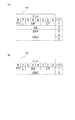
図3にヘッダ情報の概念図を例示し、この図を参照してヘッダ情報について説明する。ヘッダ情報Hには、フルヘッダ情報H1と圧縮ヘッダ情報H2とがある。図3(a)に示すフルヘッダ情報H1の1バイト目には、当該フルヘッダ情報H1を含むマルチリンクフレームMFを伝送する回線の番号(CT:Channel Tag)と、当該マルチリンクフレームMFを伝送する順番を示す番号(SN:Serial Number)と、マルチリンク通信用の伝送回線として使用される回線のうち回線番号(CT)の最も大きい回線により当該マルチリンクフレームMFが伝送されることを示すフラグ(L:Last)と、当該マルチリンクフレームMFの種類を示すフラグ(FT:Frame Type)とが記憶される。マルチリンクフレームMFの種類としては、制御データ用のマルチリンクフレームMFと、映像・音声等の一般データ用のマルチリンクフレームMFとがある。また、フルヘッダ情報H1の2バイト目には、マルチリンクフレームMFに格納される分割データの1個分の大きさを示すSS(バイト数)が記憶される。フルヘッダ情報H1の3バイト目には、一のマルチリンクフレームMFに格納される分割データの個数を示すSPF(個数)が記憶される。フルヘッダ情報H1の4〜5バイト目には、ヘッダ情報Hが正常に伝送されたか否かを示すCRC(Cyclic Redundancy Check)情報が記憶される。
【0031】
一方、図3(b)に示す圧縮ヘッダ情報H2の1バイト目には、上述したCT、SN、LおよびFTが記憶され、2バイト目には、CRC情報が記憶される。このように、圧縮ヘッダ情報H2には、フルヘッダ情報H1に含まれるSSおよびSPFが記憶されない。
【0032】
本実施形態においては、後述するSS・SPFテーブルに格納されているSSおよびSPFを用いるため、ヘッダ情報Hとしては、圧縮ヘッダ情報H2のみを用いる。これにより、伝送データの縮減を図ることが可能となる。
【0033】
図4を参照して上述したマルチリンクフレーム復号部13Bの結合処理について説明する。なお、説明を簡略化するために、マルチリンク通信を、2つの伝送回線CH1,CH2で行う場合について説明する。また、図4に示す各マルチリンクフレームMFには、マルチリンクフレームMFが伝送された順番を示す番号(SN)が便宜的に表示されており、SNとして0〜7までの数字が割り振られている。図4に示す伝送回線CH1から伝送されるマルチリンクフレームMFのLは、OFF状態となり、伝送回線CH2から伝送されるマルチリンクフレームMFのLは、ON状態となる。これは、伝送回線CH1の回線番号(CT)が“1”であり、伝送回線CH2の回線番号(CT)が“2”であるため、回線番号(CT)が最も大きい回線となる伝送回線CH2から伝送されるマルチリンクフレームMFのLがON状態に設定されるためである。
【0034】
まず、受信側JGのデータ伝送装置1のマルチリンクフレーム復号部13Bは、伝送回線CH1,CH2ごとに受信したマルチリンクフレームMFから同期フラグFを検索する。マルチリンクフレーム復号部13Bは、伝送回線CH1,CH2ごとに受信したマルチリンクフレームMFから同期フラグFを検出すると、検出した同期フラグFの直後に続く圧縮ヘッダ情報H2に含まれるSNとLを参照する。マルチリンクフレーム復号部13Bは、圧縮ヘッダ情報H2に含まれるSNとLを参照した結果、伝送回線CH1と伝送回線CH2からそれぞれ受信したマルチリンクフレームMFのSNが同一となるマルチリンクフレームMF同士を、送信側SGのデータ伝送装置1から同じタイミングで送信されたマルチリンクフレームMFであると判断する。具体的に説明すると、図4に示すように伝送回線CH1と伝送回線CH2との間に遅延差(D2−D1)が発生している場合に、受信側JGのデータ伝送装置1のマルチリンクフレーム復号部13Bは、伝送開始からD1[msec]後に回線CH1でSNが“0”であるマルチリンクフレームMFの同期フラグFを検出し、伝送開始からD2[msec]後に回線CH2でSNが“0”であるマルチリンクフレームMFの同期フラグFを検出する。この場合に、マルチリンクフレーム復号部13Bは、これらのマルチリンクフレームMF同士を送信側SGのデータ伝送装置1から同じタイミングで送信されたマルチリンクフレームMFであると判断する。また、受信側JGのデータ伝送装置のマルチリンクフレーム復号部13Bは、LがON状態であるマルチリンクフレームMFを伝送する伝送回線が、マルチリンク通信用の伝送回線として使用される回線のうち回線番号(CT)の最も大きい回線、すなわちマルチリンク通信用の最後の伝送回線であると判断する。このように、各伝送回線CH1,CH2により伝送されたマルチリンクフレームMFの同期をとることにより、各伝送回線CH1,CH2から受信したデータを一の多重化データに結合することができる。すなわち、同期のとれた各マルチリンクフレームMFに含まれる分割データを、回線番号(CT)の順番にしたがって、SSバイトずつ交互に結合していくことにより、各伝送回線CH1,CH2から受信したデータを一の多重化データに結合することができる。これにより、送信側SGのデータ伝送装置において多重化データから分割されたデータを、元の多重化データに復元することができる。
【0035】
次に、図1に示す判定部14は、他のデータ伝送装置から受信したマルチリンクフレームMFに含まれる圧縮ヘッダ情報H2に基づいて、マルチリンク通信に使用される伝送回線が増減されたか否かを判定する(判定処理)。
【0036】
ここで、図5を参照して判定部14の判定処理について説明する。なお、説明を簡略化するために、マルチリンク通信を2つの伝送回線CH1,CH2で行っている際に、新たな伝送回線CH3がマルチリンク通信の対象に追加された場合について説明する。また、図5に示す各マルチリンクフレームMFには、マルチリンクフレームMFが送信された順番を示す番号(SN)が便宜的に表示されており、このSNとして0〜7までの数字が割り振られている。
【0037】
まず、送信側SGにおける伝送回線CH1,CH2から送信されたマルチリンクフレームMFのうち、SNが“0”から“4”までのマルチリンクフレームMFについては、伝送回線CH1から送信されたマルチリンクフレームMFのLがOFF状態に設定され、伝送回線CH2から送信されたマルチリンクフレームMFのLがON状態に設定されている。これは、伝送回線CH1の回線番号(CT)が“1”であり、伝送回線CH2の回線番号(CT)が“2”であるため、回線番号(CT)がより大きい伝送回線CH2のLがON状態に設定されるためである。なお、Lは、上述したようにマルチリンク通信用の伝送回線として使用される伝送回線のうち回線番号(CT)の最も大きい伝送回線により当該マルチリンクフレームMFが伝送されることを示すフラグである。
【0038】
次に、送信側SGにおいて、SNが“4”であるマルチリンクフレームMFが送信された後に、伝送回線CH3がマルチリンク通信の対象となる伝送回線として新たに追加される。この場合に、送信側SGのデータ伝送装置のマルチリンク部13は、これ以降(SNが“5”以降)に回線CH2から送信されるマルチリンクフレームMFのLをON状態からOFF状態に変更し、回線CH3から送信されるマルチリンクフレームMFのLをON状態に設定する。これは、回線CH3の回線番号(CT)が“3”であるため、回線番号(CT)が最も大きい回線CH3から伝送されるマルチリンクフレームMFのLがON状態に設定されるためである。
【0039】
一方、受信側JGにおける伝送回線CH1,CH2から受信されたマルチリンクフレームMFのうち、SNが“0”から“4”までのマルチリンクフレームMFについては、伝送回線CH1から受信されたマルチリンクフレームMFのLがOFF状態に設定され、伝送回線CH2から受信されたマルチリンクフレームMFのLがON状態に設定されている。したがって、受信側JGのデータ伝送装置のマルチリンクフレーム構成部13Aは、各伝送回線CH1,CH2からそれぞれ受信したマルチリンクフレームMFの同期をとることにより、各伝送回線CH1,CH2から受信したデータを一の多重化データに結合する。ここで、受信側JGのデータ伝送装置のマルチリンクフレーム復号部13Bは、伝送回線CH2から受信されたマルチリンクフレームMFがマルチリンク通信用の最後の伝送回線から受信されたマルチリンクフレームMFであると判断する。そしてこのように判断した場合に、受信側JGのデータ伝送装置のマルチリンクフレーム復号部13Bは、この次に同期をとる処理の対象となるマルチリンクフレームMFのSNの値を1つ繰り上げることとなる。
【0040】
次に、受信側JGのデータ伝送装置のマルチリンクフレーム復号部13Bは、各伝送回線CH1,CH2からそれぞれ受信したマルチリンクフレームMFに基づいて、SNが“5”であるマルチリンクフレームMFの同期をとる。この場合に、受信側JGのデータ伝送装置のマルチリンクフレーム復号部13Bは、伝送回線CH2から受信されたマルチリンクフレームMFのLがON状態からOFF状態に変更されていることを検知し、SNが“5”であるマルチリンクフレームMFが、伝送回線CH3からも受信されることを認識する。したがって、受信側JGのデータ伝送装置のマルチリンクフレーム復号部13Bは、伝送回線CH3から受信されたマルチリンクフレームMF(SNが“5”)のLがON状態であることを確認することにより、マルチリンク通信用の最後の伝送回線が伝送回線CH2から伝送回線CH3に変更されたことを認識する。すなわち、伝送回線数が2回線から3回線に増加されたことを認識する。
【0041】
なお、伝送回線数が減少する場合については、上述した増加の場合と同様にして、ある伝送回線から伝送されたマルチリンクフレームMFのLがOFF状態からON状態に変わったことを検知した場合に、そのマルチリンクフレームMFを伝送した伝送回線よりも回線番号(CT)の大きい伝送回線がマルチリンク通信の対象から除外されたことを認識すればよい。
【0042】
また、ここでは伝送回線数の増加の判断をLの内容により判断しているが、回線数の増加の判断はこれに限られず、例えば、伝送回線から受信したマルチリンクフレームMFの回線番号(CT)により判断してもよい。すなわち、受信したマルチリンクフレームMFの回線番号(CT)が、これまでに受信されているマルチリンクフレームMFの回線番号(CT)とは異なる場合に、新たに伝送回線が増加されたことを認識するようにしてもよい。
【0043】
次に、図1に示す回線入出力部15は、マルチリンク通信の対象となる伝送回線数に基づいて、SS・SPFテーブルを参照し、一のマルチリンクフレームMFに含まれるペイロードPLの大きさを変更する。また、回線入出力部15は、マルチリンク通信の対象となる伝送回線数を増減した時点、あるいは伝送回線数の増減を確認した時点で、ペイロードPLの大きさを変更する。なお、この変更の時期は、伝送回線数を増減した時点や、伝送回線数の増減を確認した時点に限られない。例えば、伝送回線数が変更された後、あるいは伝送回線数の変更が確認された後から、各伝送回線で数フレーム(伝送データの量)送受信した後にペイロードPLの大きさを変更することとしてもよい。このように伝送回線数の変化とペイロードPLの大きさを変更するタイミングをずらすことにより、各伝送回線間に遅延が発生した場合でも、確実にペイロードPLの大きさを変更することが可能となる。
【0044】
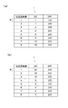
ここで、図6を参照してSS・SPFテーブルについて説明する。図6(a),(b)に示すように、SS・SPFテーブルTは、伝送回線数と、SSと、SPFとをそれぞれ対応付けて一組にしたSS・SPFレコードRを複数有している。
【0045】
図6(a)に示すSS・SPFテーブルTは、伝送回線数が増加するにしたがって、“SS×SPF”のパターン(データの分割パターン)により算出されるペイロードPLの大きさ(データ量)が増加するように、当該テーブルに格納される各値が設定されている。このSS・SPFテーブルTは、例えば、伝送回線数が増加していくと、各伝送回線間に遅延が生じる可能性も高くなることを考慮して、SSおよびSPFの値のパターンが設定されたものである。すなわち、伝送回線数を増加することにより各伝送回線間に遅延が生じた場合であっても、マルチリンクフレームMFに含まれるペイロードPLの大きさを大きくすることによって、マルチリンクフレームMFの同期がとり損なわれる事態を低減させることができる。
【0046】
一方、図6(b)に示すSS・SPFテーブルTは、伝送回線数が増加するにしたがって、“SS×SPF”のパターンにより算出されるペイロードPLの大きさが減少するように、当該テーブルに格納される各値が設定されている。このSS・SPFテーブルTは、例えば、受信側の受信バッファ容量が小さくて全ての伝送回線で受信バッファを共用している場合を考慮して、SSおよびSPFの値が設定されたものである。すなわち、伝送回線数が増加することにより一回線あたりに割り当てられる受信バッファ容量が減少していくような場合であっても、マルチリンクフレームMFに含まれるペイロードPLの大きさを小さくすることによって、受信バッファが不足してしまう事態を低減させることができる。
【0047】
このようなSS・SPFテーブルTは、例えば、送信側のデータ伝送装置あるいは受信側のデータ伝送装置のいずれか一方の装置におけるバッファ容量に基づいて当該一方の装置で生成される。そして、この一方の装置から他方の装置に対して生成されたテーブルの内容が通知されることにより、両装置間におけるSS・SPFテーブルTの内容が一致する。
【0048】
なお、データ伝送装置1の機能構成は、図1に示した構成に限られない。例えば、データ伝送送信装置として、映像符号化部11Aaと、音声符号化部11Baと、通信制御部11Cと、多重部12Aと、マルチリンクフレーム構成部13Aと、判定部14と、回線入出力部15とを有することとしてもよい。また、データ伝送受信装置として、映像復号部11Abと、音声復号部11Bbと、通信制御部11Cと、分離部12Bと、マルチリンクフレーム復号部13Bと、判定部14と、回線入出力部15とを有することとしてもよい。
【0049】
次に、図7から図10を参照して本実施形態におけるデータ伝送装置の動作を説明する。まず、データ伝送装置の概要動作について図7および図8を参照して説明する。図7は、各データ伝送装置間において伝送回線数が変更されていない状態でマルチリンク通信が行われている際の動作を示すシーケンス図である。図8は、各データ伝送装置間においてマルチリンク通信が行われている際に伝送回線数が変更された場合の動作を示すシーケンス図である。なお、ここで説明する動作は、各データ伝送装置間において、マルチリンク通信用に割り当てられた複数の回線を利用して映像データや音声データ等の送受信が行われる際に、それぞれの端末間で行われる動作である。
【0050】
まず、図7に示すように、第1のデータ伝送装置と第2のデータ伝送装置との間で、SS・SPFテーブルTの内容を決定するテーブル決定処理が行われる(ステップS1)。なお、このテーブル決定処理の詳細については、後述する。
【0051】
次に、第1のデータ伝送装置は、上述したテーブル決定処理により決定されたSS・SPFテーブルTに基づいてマルチリンクフレームMFを生成し、このマルチリンクフレームMFを含むデータを複数の伝送回線CH1〜CHx(xは正の整数)を介して第2のデータ伝送装置に送信する(ステップS2)。すなわち、第1のデータ伝送装置は、“x”回線に対応するSSおよびSPFに基づいてマルチリンクフレームMFを生成するとともに、“x”回線の伝送回線を使用して第2のデータ伝送装置にデータを送信する。
【0052】
次に、第2のデータ伝送装置は、第1のデータ伝送装置から送信されたデータを受信するとともに、受信したマルチリンクフレームMFの圧縮ヘッダ情報H2に含まれる回線番号(CT)およびLに基づいて、伝送回線数が増減されたか否かを判定する判定処理を行う(ステップS3)。なお、この判定処理の詳細については、後述する。
【0053】
第2のデータ伝送装置は、判定処理において伝送回線数が増減されていないと判定された場合には、SS・SPFテーブルTに基づいてマルチリンクフレームMFを生成し、このマルチリンクフレームMFを含んだデータを複数の伝送回線CH1〜CHxを介して第1のデータ伝送装置に送信する(ステップS4)。
【0054】
次に、第1のデータ伝送装置は、第2のデータ伝送装置から送信されたデータを受信するとともに、受信したマルチリンクフレームMFの圧縮ヘッダ情報H2に含まれる回線番号(CT)およびLに基づいて、伝送回線数が増減されたか否かを判定する判定処理を行う(ステップS5)。そして、この判定処理において伝送回線数が増減されていないと判定された場合に、第1のデータ伝送装置は、第2のデータ伝送装置に対するデータ送信をそのまま継続する。
【0055】
このようにして、第1のデータ伝送装置と第2のデータ伝送装置との間では、伝送回線を“x”回線使用したマルチリンク通信が継続して行われる。
【0056】
次に、図8を参照して、第1のデータ伝送装置と第2のデータ伝送装置との間でマルチリンク通信が行われている際に、伝送回線数が変更された場合の動作について説明する。なお、ここで説明する動作は、“x”回線使用したマルチリンク通信から“y”(yは正の整数)回線使用したマルチリンク通信に変更する際の動作である。
【0057】
まず、第1のデータ伝送装置は、マルチリンク通信の対象となる伝送回線数を“x”から“y”に変更する(ステップS11)。次に、第1のデータ伝送装置は、SS・SPFテーブルTから伝送回線数“y”に対応するSSおよびSPFのパターンを取得する(ステップS12)。そして、取得したSSおよびSPFに基づいてマルチリンクフレームMFを生成し、このマルチリンクフレームMFを含むデータを変更後の伝送回線CH1〜CHyを介して第2のデータ伝送装置に送信する(ステップS13)。すなわち、第1のデータ伝送装置は、“y”回線の伝送回線を使用して第2のデータ伝送装置にデータを送信する。
【0058】
次に、第2のデータ伝送装置は、第1のデータ伝送装置から送信されたデータを受信するとともに、受信したマルチリンクフレームMFの圧縮ヘッダ情報H2に含まれる回線番号(CT)およびLに基づいて、伝送回線数が増減されたか否かを判定する判定処理を行う(ステップS14)。なお、この判定処理の詳細については、後述する。
【0059】
第2のデータ伝送装置は、判定処理において伝送回線数が“x”から“y”に変更されていると判定された場合には、SS・SPFテーブルTから伝送回線数“y”に対応するSSおよびSPFのパターンを取得する(ステップS15)。そして、第2のデータ伝送装置は、取得したSSおよびSPFに基づいてマルチリンクフレームMFを生成し、このマルチリンクフレームMFを含んだデータを複数の伝送回線CH1〜CHyを介して第1のデータ伝送装置に送信する(ステップS16)。
【0060】
このように伝送回線が“x”回線から“y”回線に変更された場合でも、SS・SPFテーブルTから変更後の伝送回線数“y”に対応するSSおよびSPFのパターンを取得することができるため、マルチリンクフレームMFのヘッダ情報として、SSおよびSPFが格納されていない圧縮ヘッダ情報H2を使用することができる。これにより、マルチリンク通信における回線の伝送効率を向上させることができる。また、予めSSおよびSPFのパターンを記憶したSS・SPFテーブルTを設けることにより、伝送回線数の変化に応じてSSおよびSPFのパターンを取得することで、SSおよびSPFの値を変更させることができるため、処理負荷を軽減させることができる。
【0061】
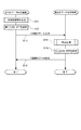
次に、図9を参照して、上述したテーブル決定処理の動作について説明する。まず、第1のデータ伝送装置は、自装置の受送信時におけるバッファ容量および端末能力等を考慮して生成したSS・SPFテーブルTの内容を、第2のデータ伝送装置に通知する(ステップS21)。
【0062】
次に、第2のデータ伝送装置は、第1のデータ伝送装置から受信したSS・SPFテーブルTの内容が、自装置の受送信時におけるバッファ容量および端末能力等で許容できる範囲のものであるか否かを判定する(ステップS22)。この判定がYESの場合(ステップS22;YES)に、第2のデータ伝送装置は、第1のデータ伝送装置から受信したSS・SPFテーブルTの内容に同意する旨の応答をする(ステップS23)。
【0063】
一方、ステップS22の判定において、許容できない範囲のものであると判定された場合(ステップS22;NO)に、第2のデータ伝送装置は、自装置の受送信時におけるバッファ容量および端末能力等を考慮して生成したSS・SPFテーブルTの内容を、第1のデータ伝送装置に通知する(ステップS24)。
【0064】
このように、本実施形態におけるデータ伝送方法では、各データ伝送装置の受送信時におけるバッファ容量および端末能力等を考慮して生成されたSS・SPFテーブルTを用いることができるため、マルチリンク通信を、各データ伝送装置の能力に応じてより効率的に行うことができる。
【0065】
なお、通信相手側のデータ伝送装置から受信したSS・SPFテーブルTが許容できない範囲のものであると判定された場合には、ヘッダ情報HとしてSSおよびSPFを含むフルヘッダ情報H1を使用する旨の応答をすることとしてもよい。この場合には、従来から行われているフルヘッダ情報H1を使用したマルチリンク通信を行えばよい。
【0066】
次に、図10を参照して、上述した判定処理の動作について説明する。まず、データ伝送装置は、マルチリンクフレームMFが伝送された順番を示す番号であるSNを初期値の“0”にセットする(ステップS25)。なお、本実施形態におけるSNは0〜7の自然数で表されることとする。また、SNにはマルチリンクフレームMFが伝送された順番として“0”から“7”の順に番号が振られ、“7”の次は、再度“0”から順に番号が振られることとする。また、以下における説明では、現時点においてデータの結合処理の対象となるマルチリンクフレームMFのSNをSNnと記載し、このSNnの1つ前の順番を示すSNをSNmと記載する。
【0067】
次に、データ伝送装置は、SNnの番号が振られたマルチリンクフレームMFを、受信バッファに格納されたデータの中から検出する(ステップS26)。そして、データ伝送装置は、検出したマルチリンクフレームMFに含まれる回線番号(CT)およびLを、SNnに対応させてメモリに格納させる(ステップS27)。
【0068】
次に、データ伝送装置は、SNnに対応するCTが、SNmに対応するCTに存在するか否かを判定する(ステップS28)。すなわち、データ伝送装置は、SNnに対応するCTが、新たに検出された回線番号(CT)に該当するか否かを判定する。なお、この判定は、初期処理時(ステップS25においてSNnに最初に“0”が格納されている際に行われる処理のとき)には行われない。この初期処理時にはSNmは存在しないからである。また、以下に説明するステップS29〜S32までの処理についても、同様の理由により初期処理時には行われない。
【0069】
ステップS28における判定の結果がNOである場合(ステップS28;NO)には、処理をステップS30に移行する。一方、ステップS28において、SNnに対応するCTがSNmに対応するCTに存在すると判定された場合(ステップS28;YES)に、データ伝送装置は、SNmに対応するLが“ON”状態であり、かつSNnに対応するLが“OFF”状態であるか否かを判定する(ステップS29)。すなわち、データ伝送装置は、同一の回線番号(CT)においてLが“ON”状態から“OFF”状態に変更されたか否かを判定する。この判定の結果がYESである場合(ステップS29;YES)に、データ伝送装置は、伝送回線数が増やされたと判定し(ステップS30)、処理をステップS33に移行する。
【0070】
一方、ステップS29における判定の結果がNOである場合(ステップS29;NO)に、データ伝送装置は、SNmに対応するLが“OFF”状態であり、かつSNnに対応するLが“ON”状態であるか否かを判定する(ステップS31)。すなわち、データ伝送装置は、同一の回線番号(CT)においてLが“OFF”状態から“ON”状態に変更されたか否かを判定する。この判定の結果がYESである場合(ステップS31;YES)に、データ伝送装置は、伝送回線数が減らされたと判定する(ステップS32)。一方、ステップS31における判定の結果がNOである場合(ステップS31;NO)には、処理をステップS33に移行する。
【0071】
次に、データ伝送装置は、SNnを有するマルチリンクフレームMFの検出がすべて終了したか否かを判定する(ステップS33)。この検出について具体的に説明すると、例えば、SNnに対応するLが“ON”状態であるマルチリンクフレームMFが既に検出され、さらにそのマルチリンクフレームMFに対応する回線番号(CT)以下の回線番号(CT)を有するマルチリンクフレームMFが全て検出されているか否かにより判定すればよい。Lが“ON”状態であるマルチリンクフレームMFの回線番号(CT)が、そのSNnにおける最大の回線番号(CT)となるからである。
【0072】
ステップS33における判定の結果がNOである場合(ステップS33;NO)に、データ伝送装置は、処理をステップS26に移行する。一方、ステップS33において、SNnを有するマルチリンクフレームMFの検出がすべて終了したと判定された場合(ステップS33;YES)に、データ伝送装置は、現時点におけるマルチリンク通信の対象となる回線数を算出する(ステップS34)。この算出について具体的に説明すると、例えば、メモリに格納されているSNnに対応するCTの総数を回線数として算出すればよい。
【0073】
次に、データ伝送装置は、SNnを1つ繰り上げてから、処理をステップS26に移行する(ステップS35)。
【0074】
以上のように、マルチリンク通信の対象とされている伝送回線数に基づいて、マルチリンクフレームMFに含まれるペイロードPLの大きさ(データ量)あるいはSS・SPFのパターン(データの分割パターン)を制御することができるため、伝送回線数に変化が生じた場合には、変化後の伝送回線数に基づいてペイロードPLの大きさあるいはSS・SPFのパターンを制御することができる。すなわち、変化後の伝送回線数に好適なペイロードPLあるいはSS・SPFのパターンに基づいて生成されたマルチリンクフレームMFにより、データの伝送が行われるため、マルチリンク通信における伝送回線の伝送効率を向上させることができる。
【0075】
また、伝送回線数に対応してペイロードPLの大きさを記憶するSS・SPFテーブルを参照することにより、伝送回線数に対応するSSとSPFのパターン(ペイロードPLの大きさ)を取得することができるため、マルチリンクフレームMFのヘッダ情報を圧縮ヘッダ情報H2のみにすることができる。これによりマルチリンクフレームMFのヘッダ情報にフルヘッダ情報H1を用いる必要がなくなり、その分マルチリンク通信における回線の伝送効率を向上させることができる。さらに、SS・SPFテーブルから伝送回線数の変化に応じたSSおよびSPFのパターンを取得することで、容易にSSおよびSPFの値を変更させることができるため、処理負荷を軽減させることができる。
【0076】
また、H.324 AnnexHにおけるデータの受信側では、受信した全てのマルチリンクフレームのヘッダ情報を参照して、ペイロードの大きさが変更されているか否かを確認しているが、本発明においては、マルチリンクフレームのヘッダ情報に圧縮ヘッダ情報のみを用いるため、全てのマルチリンクフレームのヘッダ情報を参照して、ペイロードの大きさが変更されているか否かを確認する必要がない。したがって、その分だけ、処理負荷がを低減することができる。
【0077】
【発明の効果】
本発明に係るデータ伝送方法およびデータ伝送装置によれば、マルチリンク通信における回線の伝送効率を向上させるとともに処理負荷を軽減させることができる。
【図面の簡単な説明】
【図1】実施形態におけるデータ伝送装置の機能構成図である。
【図2】マルチリンクフレーム構成部の機能を説明するための図である。
【図3】(a)はフルヘッダ情報の概念図であり、(b)は圧縮ヘッダ情報の概念図である。
【図4】マルチリンクフレーム復号部の機能を説明するための図である。
【図5】判定部の機能を説明するための図である。
【図6】(a),(b)は、SS・SPFテーブルに格納されるテーブル値の一例を示す図である。
【図7】本実施形態におけるデータ伝送装置の動作を示すフローチャートである。
【図8】本実施形態におけるデータ伝送装置の動作を示すフローチャートである。
【図9】本実施形態におけるデータ伝送装置の動作を示すフローチャートである。
【図10】本実施形態におけるデータ伝送装置の動作を示すフローチャートである。
【図11】従来技術におけるデータ伝送の機能構成図である。
【符号の説明】
1・・・データ伝送装置、11・・・データ入出力部、11Aa・・・映像符号化部、11Ab・・・映像復号部、11Ba・・・音声符号化部、11Bb・・・音声復号部、11C・・・通信制御部、11CA・・・H245処理部、11CB・・・SRP処理部、12A・・・多重部、12B・・・分離部、13A・・・マルチリンクフレーム構成部、13B・・・マルチリンクフレーム復号部、14・・・判定部、15・・・回線入出力部、T・・・SS・SPFテーブル。[0001]
TECHNICAL FIELD OF THE INVENTION
The present invention relates to a data transmission method, a data transmission device, and a data transmission system.
[0002]
[Prior art]
Conventionally, the H.32x series standardized by ITU-T (International Telecommunication Union-Telecommunication Standardization Division) has been known as a real-time video communication system such as a videophone. In this method, a plurality of input data, for example, video data and audio data are combined into one data for communication. Further, in the H.32x series, various extension models are defined, and in H.324 Annex H, one of them, a multi-path for transmitting one data by using a plurality of lines (channels). It specifies the link communication. The technology related to H.324 AnnexH is disclosed in
[0003]
With reference to FIG. 11, a functional configuration for processing video / audio data using H.324 Annex H will be described. The video encoding unit J1 encodes the input video using a video encoding method such as MPEG4. The audio encoding unit J2 encodes the input audio using an audio encoding method such as AMR. The communication control unit J3 controls a communication system such as a capability exchange between communication devices using a message specified by H.245. The multiplexing unit J4 adopts multiplexing processing based on the H223 system, and the mobile multilinking unit J5 that converts video / audio data into one multiplexed data uses the multilinking according to AnnexH for the converted multiplexed data. Processing is performed to divide the multiplexed data into a plurality.
[0004]
Next, the procedure of the multilink process in the mobile multilink unit J5 will be described with reference to FIG. First, the multiplexed data D1 is divided into SS (Sampling Size) bytes, and is sequentially distributed to a transmission line buffer. At the time when the SS byte data is accumulated in SPF (Sample Per Frame), the multilink frame MF is generated by adding a synchronization flag F, header information H, and CRC information of the header information to the data. The multi-link frame MF is transmitted to another terminal. As shown in FIG. 3, the header information H includes full header information H1 and compressed header information H2. The header information H includes the number (CT) of the line transmitting the multilink frame and the line having the largest CT value among the lines used as the transmission line for the multilink communication. Of the multilink frame, a number (SN) indicating the order of transmitting the multilink frame, and a flag (FT) indicating the type of the multilink frame. Further, the full header information H1 further includes the size of SS and SPF.
[0005]
Further, a procedure of a restoration process of the divided data performed in the mobile multilink unit J5 will be described. First, a synchronization flag is searched for each line, and if a synchronization flag is detected, the SN and L of the header information immediately after the synchronization flag are referred to. At this time, if the SN of each line is the same, it can be determined that the multilink frame is data transmitted at the same timing. If the L flag is in the "ON" state, it is known that the line is the last line. In this way, the data transmitted from each line can be synchronized, and the multiplexed data divided and transmitted by each line can be restored to the original multiplexed data. Since SN can only take a value from 0 to 7, synchronization may not be achieved depending on the magnitude of the transmission delay. For this reason, the values of SS and SPF are set in consideration of the communication environment and the buffer size on the receiving side. After being restored to the original multiplexed data, the data is divided into video data, audio data, and H.245 data according to the H.223 scheme, and each is decoded. Then, by simultaneously reproducing the decoded data, real-time video communication becomes possible.
[0006]
By the way, in the above-mentioned multilink communication in H.324 AnnexH, a plurality of data (video data, audio data, etc.) to be divided and transmitted for each line are stored in a multilink frame and transmitted. Here, as described above, the amount of data stored in the multilink frame is determined by the values of SS and SPF included in the header information. It is desirable that the values of SS and SPF be changed in accordance with changes in various factors such as the transmission status of a line in order to improve transmission efficiency. For example, when a burst error is likely to occur, the effect of the burst error can be reduced by reducing the value of SS. Further, when a delay occurs in the line, the allowable delay amount can be increased by increasing the value of SS × SPF (payload).
[0007]
[Non-patent document 1]
"ITU-T Recommendation on CD-ROM", Disc-2, T-REC-H.324-200011-I! AnnH! MSW-E.zip, November 2000 (zip file) March 2000 (CD- ROM)
[Problems to be solved by the invention]
However, in order to change the values of SS and SPF in the above-described multilink communication, it is necessary to add information indicating the values of SS and SPF to be set to the header information of the multilink frame. Therefore, when the size of the payload and the contents of the SS and SPF are frequently changed according to the transmission status of the line, the transmission efficiency of the line is increased by the value of the SS and SPF added to the header information. There was a problem that it would decrease. When changing the size of the payload or the contents of the SS and SPF, a synchronization flag different from the synchronization flag that is normally used is used, and both the transmission side and the reception side confirm the change contents. You need to interact. Therefore, there is a problem that complicated processing is required and the processing load is increased.
[0008]
Therefore, the present invention provides a data transmission method, a data transmission device, and a data transmission system that can improve the transmission efficiency of a line in multilink communication and reduce the processing load in order to solve the above-described problems. With the goal.
[0009]
[Means for Solving the Problems]
In the data transmission method of the present invention, a transmitting terminal divides data to be transmitted, distributes the divided data to a plurality of transmission paths, transmits the data for each predetermined data amount, and A data transmission method in which a terminal receives data transmitted by being distributed to the plurality of transmission paths, and combines the received data, wherein a data amount and a data division pattern are determined based on transmission results for each transmission path. Or both of them are controlled.
[0010]
Further, the data transmission device of the present invention includes a dividing unit that divides data to be transmitted, and the data divided by the dividing unit is distributed to a plurality of transmission paths, and for each predetermined data amount, an external terminal. A transmitting means for transmitting, a receiving means for receiving data transmitted by being distributed to a plurality of transmission paths from an external terminal, a coupling means for coupling data received by the receiving means, and And a control means for controlling both or one of a data amount and a data division pattern based on the determination by the determination means.
[0011]
Also, the data transmission system of the present invention is a data transmission system for transmitting and receiving data between a first data transmission device and a second data transmission device, wherein the first data transmission device is a transmission target. A second data transmission device, comprising: a dividing unit that divides the data divided by the dividing unit; and a transmitting unit that distributes the data divided by the dividing unit to a plurality of transmission paths and transmits the data to an external terminal for each predetermined data amount. Receiving means for receiving data distributed from the external terminal to a plurality of transmission paths, combining means for combining data received by the receiving means, and a transmission path for each transmission path based on the combined data. And a control unit for controlling both or one of the data amount and the data division pattern based on the determination by the determination unit. Over data transmission system.
[0012]
According to these inventions, based on the transmission results for each transmission path, it is possible to control both or one of the data amount and the data division pattern. It is possible to control both or one of the data amount and the data division pattern based on the transmission results after the change, thereby improving the line transmission efficiency in multilink communication and reducing the processing load.
[0013]
In the data transmission method of the present invention, the transmission result is preferably the number of transmission lines used as a plurality of transmission lines.
[0014]
According to the present invention, it is possible to control both or one of the data amount and the data division pattern based on the number of transmission paths used as a plurality of transmission paths. It is possible to control both or one of the data amount and the data division pattern based on the changed number of transmission paths, thereby improving the transmission efficiency of the line in multilink communication and reducing the processing load. it can.
[0015]
In the data transmission method according to the present invention, it is preferable that the control described above controls the timing of changing both or one of the data amount and the data division pattern based on the amount of transmission data transmitted to the transmission path.
[0016]
According to the present invention, the timing for changing both or one of the data amount and the data division pattern is controlled based on the data amount transmitted to the transmission line, so that even when a delay occurs between the transmission lines, it is ensured. And / or one of the data division patterns can be changed.
[0017]
In the data transmission method according to the present invention, the above-described control refers to both or one of the data amount and the data division pattern that are defined in advance in accordance with the transmission result, so that the data amount and the data division pattern are both or It is preferable to control one. Further, in the data transmission device of the present invention, the control unit refers to both or one of the data amount and the data division pattern that are defined in advance in accordance with the transmission result, thereby controlling both the data amount and the data division pattern. Alternatively, it is preferable to control one of them. Further, in the data transmission system according to the present invention, the control unit refers to both or one of the data amount and the data division pattern that are defined in advance corresponding to the transmission result, so that both the data amount and the data division pattern are determined. Alternatively, it is preferable to control one of them.
[0018]
According to these inventions, it is possible to control both or one of the data amount and the data division pattern by referring to both or one of the data amount and the data division pattern defined in advance corresponding to the transmission result. Therefore, it is not necessary to store information indicating the data amount in the data transmitted on the transmission path itself, and the transmission efficiency of the line in the multilink communication can be improved accordingly. Furthermore, by referring to both or one of the data amount and the data division pattern according to the change in the number of transmission lines from the predetermined data amount and / or the data division pattern, the data amount and the data division pattern can be easily obtained. Or one of the divided patterns can be changed, and the processing load can be reduced.
[0019]
In the data transmission method of the present invention, both or one of the predetermined data amount and the data division pattern described above is based on the buffer capacity of data in one of the transmitting terminal and the receiving terminal. Preferably, it is determined.
[0020]
According to the present invention, since the amount of data transmitted to the transmission path can be determined based on the buffer capacity of one terminal, the data transmission in the multilink communication is determined based on the buffer capacity of the terminal. It can be done by quantity.
[0021]
In the data transmission method of the present invention, both or one of the previously defined data amount and data division pattern is preferably notified from one terminal to the other terminal, and further, the other of the notified terminals It is preferable that the terminal notifies one terminal of a response to the notification.
[0022]
According to the present invention, data transmission in multilink communication can be performed with a data amount determined in consideration of buffer capacity of both terminals, so that data can be transmitted more reliably.
[0023]
BEST MODE FOR CARRYING OUT THE INVENTION
Hereinafter, embodiments of an apparatus according to the present invention will be described with reference to the drawings. In each of the drawings, the same elements will be denoted by the same reference symbols, without redundant description.
[0024]
First, an embodiment of the present invention will be described. FIG. 1 is a diagram illustrating a functional configuration of a
[0025]
The data input /
[0026]
The
[0027]
The
[0028]
The multilink
[0029]
Here, the division processing of the multilink
[0030]
FIG. 3 illustrates a conceptual diagram of the header information, and the header information will be described with reference to FIG. The header information H includes full header information H1 and compressed header information H2. In the first byte of the full header information H1 shown in FIG. 3A, a line number (CT: Channel Tag) for transmitting the multilink frame MF including the full header information H1 and an order for transmitting the multilink frame MF are included. (SN: Serial Number) and a flag (L) indicating that the multilink frame MF is transmitted by a line having the largest line number (CT) among lines used as transmission lines for multilink communication. : Last) and a flag (FT: Frame Type) indicating the type of the multilink frame MF are stored. The types of the multilink frame MF include a multilink frame MF for control data and a multilink frame MF for general data such as video and audio. In the second byte of the full header information H1, an SS (number of bytes) indicating the size of one piece of divided data stored in the multilink frame MF is stored. In the third byte of the full header information H1, an SPF (number) indicating the number of pieces of divided data stored in one multilink frame MF is stored. In the fourth to fifth bytes of the full header information H1, CRC (Cyclic Redundancy Check) information indicating whether or not the header information H has been transmitted normally is stored.
[0031]
On the other hand, CT, SN, L, and FT described above are stored in the first byte of the compressed header information H2 shown in FIG. 3B, and CRC information is stored in the second byte. Thus, the SS and SPF included in the full header information H1 are not stored in the compressed header information H2.
[0032]
In the present embodiment, since the SS and SPF stored in the SS / SPF table described later are used, only the compressed header information H2 is used as the header information H. This makes it possible to reduce transmission data.
[0033]
With reference to FIG. 4, a description will be given of the combining process of the multilink
[0034]
First, the multilink
[0035]
Next, the
[0036]
Here, the determination process of the
[0037]
First, among the multilink frames MF transmitted from the transmission lines CH1 and CH2 on the transmission side SG, the multilink frames MF whose SNs are “0” to “4” are the multilink frames transmitted from the transmission line CH1. L of the MF is set to the OFF state, and L of the multilink frame MF transmitted from the transmission line CH2 is set to the ON state. This is because the line number (CT) of the transmission line CH1 is "1" and the line number (CT) of the transmission line CH2 is "2". This is because it is set to the ON state. Note that L is a flag indicating that the multilink frame MF is transmitted by the transmission line having the largest line number (CT) among the transmission lines used as multilink communication transmission lines as described above. .
[0038]
Next, after the transmission side SG transmits the multilink frame MF whose SN is "4", the transmission line CH3 is newly added as a transmission line to be subjected to the multilink communication. In this case, the
[0039]
On the other hand, among the multilink frames MF received from the transmission lines CH1 and CH2 on the receiving side JG, the multilink frames MF with SNs of “0” to “4” are the multilink frames MF received from the transmission line CH1. L of the MF is set to the OFF state, and L of the multilink frame MF received from the transmission line CH2 is set to the ON state. Therefore, the multilink
[0040]
Next, the multilink
[0041]
In the case where the number of transmission lines decreases, similarly to the case of the increase described above, when it is detected that the L of the multilink frame MF transmitted from a certain transmission line changes from the OFF state to the ON state. It is sufficient to recognize that a transmission line having a larger line number (CT) than the transmission line transmitting the multilink frame MF has been excluded from the target of the multilink communication.
[0042]
Here, the determination of the increase in the number of transmission lines is made based on the content of L, but the determination of the increase in the number of lines is not limited to this. For example, the line number (CT) of the multilink frame MF received from the transmission line ). That is, when the line number (CT) of the received multilink frame MF is different from the line number (CT) of the multilink frame MF received so far, it is recognized that a new transmission line has been added. You may make it.
[0043]
Next, the line input /
[0044]
Here, the SS / SPF table will be described with reference to FIG. As shown in FIGS. 6A and 6B, the SS / SPF table T has a plurality of SS / SPF records R in which the number of transmission lines, SS, and SPF are associated with each other to form one set. I have.
[0045]
The SS / SPF table T shown in FIG. 6A shows that the size (data amount) of the payload PL calculated by the “SS × SPF” pattern (data division pattern) as the number of transmission lines increases. Each value stored in the table is set so as to increase. In the SS / SPF table T, for example, a pattern of values of SS and SPF is set in consideration of a possibility that a delay may occur between transmission lines as the number of transmission lines increases. Things. That is, even when a delay occurs between the transmission lines due to an increase in the number of transmission lines, synchronization of the multilink frame MF can be synchronized by increasing the size of the payload PL included in the multilink frame MF. Mistakes can be reduced.
[0046]
On the other hand, the SS / SPF table T shown in FIG. 6B shows that the size of the payload PL calculated by the pattern of “SS × SPF” decreases as the number of transmission lines increases. Each value to be stored is set. In the SS / SPF table T, the values of SS and SPF are set in consideration of, for example, a case where the receiving buffer capacity on the receiving side is small and the receiving buffer is shared by all transmission lines. That is, even when the number of transmission lines increases and the reception buffer capacity allocated per line decreases, by reducing the size of the payload PL included in the multilink frame MF, It is possible to reduce the situation where the reception buffer runs short.
[0047]
Such an SS / SPF table T is generated by, for example, one of the transmission-side data transmission apparatus and the reception-side data transmission apparatus based on the buffer capacity of one of the apparatuses. Then, when the content of the generated table is notified from the one device to the other device, the content of the SS / SPF table T between the two devices matches.
[0048]
Note that the functional configuration of the
[0049]
Next, the operation of the data transmission device according to the present embodiment will be described with reference to FIGS. First, the general operation of the data transmission device will be described with reference to FIGS. FIG. 7 is a sequence diagram illustrating an operation when multilink communication is performed in a state where the number of transmission lines is not changed between the data transmission devices. FIG. 8 is a sequence diagram showing an operation when the number of transmission lines is changed while multilink communication is being performed between the data transmission devices. Note that the operation described here is performed between each data transmission device when transmitting and receiving video data, audio data, and the like using a plurality of lines allocated for multilink communication. This is the operation to be performed.
[0050]
First, as shown in FIG. 7, a table determination process for determining the contents of the SS / SPF table T is performed between the first data transmission device and the second data transmission device (step S1). The details of the table determination process will be described later.
[0051]
Next, the first data transmission device generates a multilink frame MF based on the SS / SPF table T determined by the above-described table determination process, and transmits data including the multilink frame MF to a plurality of transmission lines CH1. The data is transmitted to the second data transmission device via CHCHx (x is a positive integer) (step S2). That is, the first data transmission device generates the multilink frame MF based on the SS and SPF corresponding to the “x” line, and transmits the multilink frame MF to the second data transmission device using the “x” line transmission line. Send data.
[0052]
Next, the second data transmission device receives the data transmitted from the first data transmission device and, based on the line numbers (CT) and L included in the compressed header information H2 of the received multilink frame MF. Then, a determination process is performed to determine whether the number of transmission lines has been increased or decreased (step S3). The details of this determination processing will be described later.
[0053]
When it is determined in the determination process that the number of transmission lines has not been increased or decreased, the second data transmission device generates a multilink frame MF based on the SS / SPF table T, and includes the multilink frame MF. The data is transmitted to the first data transmission device via the plurality of transmission lines CH1 to CHx (step S4).
[0054]
Next, the first data transmission device receives the data transmitted from the second data transmission device and, based on the line numbers (CT) and L included in the compressed header information H2 of the received multilink frame MF. Then, a determination process is performed to determine whether the number of transmission lines has been increased or decreased (step S5). Then, when it is determined in this determination process that the number of transmission lines has not been increased or decreased, the first data transmission device continues data transmission to the second data transmission device.
[0055]
Thus, between the first data transmission device and the second data transmission device, the multilink communication using the “x” transmission line is continuously performed.
[0056]
Next, an operation when the number of transmission lines is changed while multilink communication is being performed between the first data transmission device and the second data transmission device will be described with reference to FIG. I do. The operation described here is an operation when changing from the multilink communication using the “x” line to the multilink communication using the “y” (y is a positive integer) line.
[0057]
First, the first data transmission device changes the number of transmission lines targeted for multilink communication from "x" to "y" (step S11). Next, the first data transmission device acquires the SS and SPF patterns corresponding to the number of transmission lines “y” from the SS / SPF table T (step S12). Then, a multilink frame MF is generated based on the acquired SS and SPF, and data including the multilink frame MF is transmitted to the second data transmission device via the changed transmission lines CH1 to CHy (step S13). ). That is, the first data transmission device transmits data to the second data transmission device using the "y" transmission line.
[0058]
Next, the second data transmission device receives the data transmitted from the first data transmission device and, based on the line numbers (CT) and L included in the compressed header information H2 of the received multilink frame MF. Then, a determination process is performed to determine whether the number of transmission lines has been increased or decreased (step S14). The details of this determination processing will be described later.
[0059]
When the second data transmission device determines in the determination process that the number of transmission lines has been changed from “x” to “y”, the second data transmission device corresponds to the number of transmission lines “y” from the SS / SPF table T. The SS and SPF patterns are acquired (step S15). Then, the second data transmission device generates a multilink frame MF based on the obtained SS and SPF, and transmits the data including the multilink frame MF to the first data via a plurality of transmission lines CH1 to CHy. The data is transmitted to the transmission device (step S16).
[0060]
Thus, even when the transmission line is changed from the “x” line to the “y” line, the SS and SPF patterns corresponding to the changed transmission line number “y” can be obtained from the SS / SPF table T. Therefore, compressed header information H2 in which SS and SPF are not stored can be used as header information of the multilink frame MF. Thereby, the transmission efficiency of the line in the multilink communication can be improved. Further, by providing the SS / SPF table T in which the SS and SPF patterns are stored in advance, the SS and SPF patterns are acquired according to the change in the number of transmission lines, so that the values of SS and SPF can be changed. Therefore, the processing load can be reduced.
[0061]
Next, the operation of the above-described table determination processing will be described with reference to FIG. First, the first data transmission device notifies the second data transmission device of the contents of the SS / SPF table T generated in consideration of the buffer capacity and the terminal capability at the time of transmission / reception of the own device (step S21). ).
[0062]
Next, in the second data transmission device, the content of the SS / SPF table T received from the first data transmission device is in a range that can be tolerated by its own buffer capacity and terminal capability at the time of transmission and reception. It is determined whether or not (step S22). If this determination is YES (step S22; YES), the second data transmission device responds to the effect that it agrees with the contents of the SS / SPF table T received from the first data transmission device (step S23). .
[0063]
On the other hand, if it is determined in step S22 that the data is in an unacceptable range (step S22; NO), the second data transmission apparatus determines its own buffer capacity and terminal capacity at the time of transmission and reception. The contents of the SS / SPF table T generated in consideration of this are notified to the first data transmission device (step S24).
[0064]
As described above, in the data transmission method according to the present embodiment, since the SS / SPF table T generated in consideration of the buffer capacity and the terminal capacity at the time of transmission / reception of each data transmission device can be used, the multilink communication Can be performed more efficiently depending on the capacity of each data transmission device.
[0065]
If it is determined that the SS / SPF table T received from the communication partner data transmission device is in an unacceptable range, the full header information H1 including SS and SPF is used as the header information H. A response may be made. In this case, multilink communication using the full header information H1 which has been performed conventionally may be performed.
[0066]
Next, the operation of the above-described determination processing will be described with reference to FIG. First, the data transmission device sets SN, which is the number indicating the order in which the multilink frame MF was transmitted, to the initial value “0” (step S25). Note that the SN in the present embodiment is represented by a natural number of 0 to 7. The SNs are numbered in the order of transmission of the multilink frame MF from “0” to “7”, and after “7”, the numbers are again numbered in order from “0”. In the following description, the SN of the multilink frame MF currently subjected to the data combining process is described as SNn, and the SN indicating the immediately preceding SNn is described as SNm.
[0067]
Next, the data transmission device detects the multilink frame MF numbered with SNn from the data stored in the reception buffer (step S26). Then, the data transmission device causes the memory to store the line number (CT) and L included in the detected multilink frame MF in association with SNn (step S27).
[0068]
Next, the data transmission device determines whether a CT corresponding to SNn exists in a CT corresponding to SNm (step S28). That is, the data transmission device determines whether the CT corresponding to SNn corresponds to the newly detected line number (CT). This determination is not performed during the initial processing (the processing performed when “0” is initially stored in SNn in step S25). This is because SNm does not exist during this initial processing. Also, the processing of steps S29 to S32 described below is not performed during the initial processing for the same reason.
[0069]
If the result of the determination in step S28 is NO (step S28; NO), the process proceeds to step S30. On the other hand, when it is determined in step S28 that the CT corresponding to SNn is present in the CT corresponding to SNm (step S28; YES), the data transmission device determines that L corresponding to SNm is "ON", It is determined whether L corresponding to SNn is in the “OFF” state (step S29). That is, the data transmission device determines whether or not L has been changed from the “ON” state to the “OFF” state for the same line number (CT). If the result of this determination is YES (step S29; YES), the data transmission device determines that the number of transmission lines has been increased (step S30), and shifts the processing to step S33.
[0070]
On the other hand, if the result of the determination in step S29 is NO (step S29; NO), the data transmission device sets the L corresponding to SNm to the "OFF" state and the L corresponding to SNn to the "ON" state. Is determined (step S31). That is, the data transmission device determines whether or not L has been changed from the “OFF” state to the “ON” state for the same line number (CT). If the result of this determination is YES (step S31; YES), the data transmission device determines that the number of transmission lines has been reduced (step S32). On the other hand, if the result of the determination in step S31 is NO (step S31; NO), the process proceeds to step S33.
[0071]
Next, the data transmission device determines whether or not detection of all multilink frames MF having SNn has been completed (step S33). The detection will be specifically described. For example, a multilink frame MF in which L corresponding to SNn is in the “ON” state has already been detected, and a line number lower than the line number (CT) corresponding to the multilink frame MF is further detected. The determination may be made based on whether or not all the multilink frames MF having (CT) have been detected. This is because the line number (CT) of the multilink frame MF in which L is in the “ON” state is the maximum line number (CT) in the SNn.
[0072]
If the result of the determination in step S33 is NO (step S33; NO), the data transmission device shifts the processing to step S26. On the other hand, if it is determined in step S33 that the detection of all the multilink frames MF having SNn has been completed (step S33; YES), the data transmission device calculates the number of lines to be subjected to the multilink communication at the current time. (Step S34). This calculation will be specifically described. For example, the total number of CTs corresponding to SNn stored in the memory may be calculated as the number of lines.
[0073]
Next, the data transmission device advances SNn by one, and then shifts the processing to step S26 (step S35).
[0074]
As described above, based on the number of transmission lines targeted for multilink communication, the size (data amount) of the payload PL or the SS / SPF pattern (data division pattern) included in the multilink frame MF is determined. Therefore, when the number of transmission lines changes, the size of the payload PL or the SS / SPF pattern can be controlled based on the changed number of transmission lines. That is, since data is transmitted by the multilink frame MF generated based on the payload PL or SS / SPF pattern suitable for the number of transmission lines after the change, the transmission efficiency of the transmission line in the multilink communication is improved. Can be done.
[0075]
Also, by referring to the SS / SPF table storing the size of the payload PL corresponding to the number of transmission lines, it is possible to acquire the SS and SPF patterns (size of the payload PL) corresponding to the number of transmission lines. Therefore, the header information of the multilink frame MF can be only the compressed header information H2. This eliminates the need to use the full header information H1 as the header information of the multilink frame MF, thereby improving the transmission efficiency of the line in the multilink communication. Furthermore, by obtaining the SS and SPF patterns according to the change in the number of transmission lines from the SS / SPF table, the values of SS and SPF can be easily changed, and the processing load can be reduced.
[0076]
Also, on the data receiving side in H.324 AnnexH, referring to the header information of all received multilink frames, it is checked whether the size of the payload has been changed, but in the present invention, Since only the compressed header information is used as the header information of the multilink frame, it is not necessary to check whether or not the size of the payload has been changed by referring to the header information of all the multilink frames. Therefore, the processing load can be reduced accordingly.
[0077]
【The invention's effect】
ADVANTAGE OF THE INVENTION According to the data transmission method and the data transmission apparatus according to the present invention, it is possible to improve the transmission efficiency of a line in multilink communication and reduce the processing load.
[Brief description of the drawings]
FIG. 1 is a functional configuration diagram of a data transmission device according to an embodiment.
FIG. 2 is a diagram for explaining a function of a multilink frame forming unit.
FIG. 3A is a conceptual diagram of full header information, and FIG. 3B is a conceptual diagram of compressed header information.
FIG. 4 is a diagram for explaining a function of a multilink frame decoding unit.
FIG. 5 is a diagram for explaining a function of a determination unit.
FIGS. 6A and 6B are diagrams illustrating an example of table values stored in an SS / SPF table; FIGS.
FIG. 7 is a flowchart illustrating an operation of the data transmission device according to the present embodiment.
FIG. 8 is a flowchart illustrating an operation of the data transmission device according to the present embodiment.
FIG. 9 is a flowchart illustrating an operation of the data transmission device according to the present embodiment.
FIG. 10 is a flowchart illustrating an operation of the data transmission device according to the present embodiment.
FIG. 11 is a functional configuration diagram of data transmission in the related art.
[Explanation of symbols]
DESCRIPTION OF
Claims (11)
前記伝送路ごとの伝送実績に基づいて、前記データ量とデータの分割パターンの両方または一方を制御することを特徴とするデータ伝送方法。The transmission-side terminal divides the data to be transmitted, distributes the divided data to a plurality of transmission paths, transmits the data for each predetermined amount of data, and transmits the plurality of transmission paths to the reception-side terminal. A data transmission method for receiving the data distributed and transmitted, and combining the received data,
A data transmission method, comprising: controlling both or one of the data amount and the data division pattern based on a transmission result for each transmission path.
前記分割手段により分割されたデータを複数の伝送路に振り分けて所定のデータ量ごとに、外部にある端末に送信する送信手段と、
前記外部にある端末から前記複数の伝送路に振り分けて送信されたデータを受信する受信手段と、
前記受信手段により受信されたデータを結合する結合手段と、
前記結合されたデータに基づいて、前記伝送路ごとの伝送実績を判定する判定手段と、
前記判定手段による判定に基づいて、前記データ量とデータの分割パターンの両方または一方を制御する制御手段と
を備えることを特徴とするデータ伝送装置。Division means for dividing data to be transmitted;
A transmitting unit that distributes the data divided by the dividing unit to a plurality of transmission paths and transmits the data to a terminal located outside for each predetermined data amount;
Receiving means for receiving data transmitted by being distributed to the plurality of transmission paths from the external terminal,
Combining means for combining the data received by the receiving means;
Based on the combined data, a determination unit that determines a transmission result for each of the transmission paths,
A data transmission device comprising: a control unit that controls both or one of the data amount and the data division pattern based on the determination by the determination unit.
前記第1のデータ伝送装置は、
送信の対象となるデータを分割する分割手段と、
前記分割手段により分割されたデータを複数の伝送路に振り分けて所定のデータ量ごとに、外部にある端末に送信する送信手段とを備え、
前記第2のデータ伝送装置は、
前記外部にある端末から前記複数の伝送路に振り分けて送信されたデータを受信する受信手段と、
前記受信手段により受信されたデータを結合する結合手段と、
前記結合されたデータに基づいて、前記伝送路ごとの伝送実績を判定する判定手段と、
前記判定手段による判定に基づいて、前記データ量とデータの分割パターンの両方または一方を制御する制御手段とを備えることを特徴とするデータ伝送システム。A data transmission system for transmitting and receiving data between a first data transmission device and a second data transmission device,
The first data transmission device includes:
Division means for dividing data to be transmitted;
Transmitting means for distributing the data divided by the dividing means to a plurality of transmission paths and transmitting the data to an external terminal for each predetermined data amount,
The second data transmission device includes:
Receiving means for receiving data transmitted by being distributed to the plurality of transmission paths from the external terminal,
Combining means for combining the data received by the receiving means;
Based on the combined data, a determination unit that determines a transmission result for each of the transmission paths,
A data transmission system comprising: a control unit that controls both or one of the data amount and the data division pattern based on the determination by the determination unit.
Priority Applications (4)
| Application Number | Priority Date | Filing Date | Title |
|---|---|---|---|
| JP2002367287A JP4199997B2 (en) | 2002-12-18 | 2002-12-18 | Data transmission method, data transmission apparatus, and data transmission system |
| EP20030028967 EP1432191B1 (en) | 2002-12-18 | 2003-12-17 | Data transmission method and apparatus based on a multilink protocol |
| US10/737,763 US7630413B2 (en) | 2002-12-18 | 2003-12-18 | Data transmission method, data transmission apparatus, and data transmission system |
| CNA2003101223121A CN1514620A (en) | 2002-12-18 | 2003-12-18 | Method, apparatus and system for data transmission |
Applications Claiming Priority (1)
| Application Number | Priority Date | Filing Date | Title |
|---|---|---|---|
| JP2002367287A JP4199997B2 (en) | 2002-12-18 | 2002-12-18 | Data transmission method, data transmission apparatus, and data transmission system |
Publications (2)
| Publication Number | Publication Date |
|---|---|
| JP2004201037A true JP2004201037A (en) | 2004-07-15 |
| JP4199997B2 JP4199997B2 (en) | 2008-12-24 |
Family
ID=32376280
Family Applications (1)
| Application Number | Title | Priority Date | Filing Date |
|---|---|---|---|
| JP2002367287A Expired - Fee Related JP4199997B2 (en) | 2002-12-18 | 2002-12-18 | Data transmission method, data transmission apparatus, and data transmission system |
Country Status (4)
| Country | Link |
|---|---|
| US (1) | US7630413B2 (en) |
| EP (1) | EP1432191B1 (en) |
| JP (1) | JP4199997B2 (en) |
| CN (1) | CN1514620A (en) |
Cited By (1)
| Publication number | Priority date | Publication date | Assignee | Title |
|---|---|---|---|---|
| JP2012070198A (en) * | 2010-09-23 | 2012-04-05 | Nec Engineering Ltd | Video transmission system |
Families Citing this family (11)
| Publication number | Priority date | Publication date | Assignee | Title |
|---|---|---|---|---|
| GB0421664D0 (en) * | 2004-09-29 | 2004-10-27 | Nokia Corp | Method for commuication over a lossy interface |
| US7965736B2 (en) | 2005-08-24 | 2011-06-21 | Qualcomm Incorporated | Transmission of multiplex protocol data units in physical layer packets |
| US8611258B1 (en) * | 2005-09-30 | 2013-12-17 | At&T Intellectual Property Ii, L.P. | Method and apparatus for integrating video and instant messaging application sessions |
| WO2007052994A1 (en) | 2005-11-07 | 2007-05-10 | Lg Electronics Inc. | Near field communication host controller interface |
| CN101039310B (en) * | 2006-03-16 | 2010-08-25 | 联想(北京)有限公司 | Link sharing service apparatus and communication method thereof |
| CN101039309B (en) * | 2006-03-16 | 2010-09-29 | 联想(北京)有限公司 | Link sharing service apparatus and communication method thereof |
| US8713393B2 (en) * | 2007-10-02 | 2014-04-29 | Lantiq Deutschland Gmbh | Retransmission and retransmission request in data communication systems |
| JP4623196B2 (en) * | 2008-10-08 | 2011-02-02 | 富士ゼロックス株式会社 | Image processing apparatus, image processing system, and program |
| CN101720107B (en) * | 2009-03-23 | 2013-05-29 | 上海通琅信息技术有限公司 | Multi-way integrated communication system and method for wireless multimedia transmission |
| JP5772132B2 (en) * | 2011-03-25 | 2015-09-02 | 富士通株式会社 | Data transfer apparatus, data transfer method, and information processing apparatus |
| CN107018399A (en) * | 2017-03-28 | 2017-08-04 | 北京犀牛数字互动科技有限公司 | Image data transfer method and device |
Family Cites Families (13)
| Publication number | Priority date | Publication date | Assignee | Title |
|---|---|---|---|---|
| US5231649A (en) | 1991-08-08 | 1993-07-27 | Ascend Communications, Inc. | Method and apparatus for dynamic bandwidth allocation in a digital communication session |
| JPH05153183A (en) | 1991-11-27 | 1993-06-18 | Hitachi Ltd | Data transferring system using plural links |
| WO1998037658A2 (en) * | 1997-02-24 | 1998-08-27 | Picturetel Corporation | Channel aggregation having low latency and overhead |
| US6411629B1 (en) * | 1998-12-29 | 2002-06-25 | Northern Telecom Limited | Data interleaving method |
| US6335933B1 (en) * | 1999-05-21 | 2002-01-01 | Broadcom Homenetworking, Inc. | Limited automatic repeat request protocol for frame-based communication channels |
| US6999429B1 (en) * | 2000-03-03 | 2006-02-14 | Telefonaktiebolaget Lm Ericsson | Access technology integrated header compression |
| EP1148687A1 (en) * | 2000-04-20 | 2001-10-24 | Telefonaktiebolaget L M Ericsson (Publ) | Communication device |
| FR2809577B1 (en) * | 2000-05-25 | 2002-10-18 | Mitsubishi Electric Inf Tech | DATA TRANSMISSION METHOD COMBATING THE DEGRADATION OF QUALITY OF SERVICE |
| US7082569B2 (en) * | 2001-01-17 | 2006-07-25 | Outlooksoft Corporation | Systems and methods providing dynamic spreadsheet functionality |
| US7054291B2 (en) * | 2001-01-22 | 2006-05-30 | Telefonaktiebolaget Lm Ericsson (Publ) | Method of and system for mobile station abbreviated point-to-point protocol negotiation |
| US6490296B2 (en) * | 2001-02-28 | 2002-12-03 | Symmetricom, Inc. | Multi-link segmentation and reassembly for bonding multiple PVC's in an inverse multiplexing arrangement |
| US6879590B2 (en) * | 2002-04-26 | 2005-04-12 | Valo, Inc. | Methods, apparatuses and systems facilitating aggregation of physical links into logical link |
| US7277419B2 (en) * | 2002-08-30 | 2007-10-02 | Intel Corporation | Supporting disparate packet based wireless communications |
-
2002
- 2002-12-18 JP JP2002367287A patent/JP4199997B2/en not_active Expired - Fee Related
-
2003
- 2003-12-17 EP EP20030028967 patent/EP1432191B1/en not_active Expired - Fee Related
- 2003-12-18 CN CNA2003101223121A patent/CN1514620A/en active Pending
- 2003-12-18 US US10/737,763 patent/US7630413B2/en not_active Expired - Fee Related
Cited By (1)
| Publication number | Priority date | Publication date | Assignee | Title |
|---|---|---|---|---|
| JP2012070198A (en) * | 2010-09-23 | 2012-04-05 | Nec Engineering Ltd | Video transmission system |
Also Published As
| Publication number | Publication date |
|---|---|
| CN1514620A (en) | 2004-07-21 |
| JP4199997B2 (en) | 2008-12-24 |
| EP1432191B1 (en) | 2012-02-22 |
| US20040179556A1 (en) | 2004-09-16 |
| US7630413B2 (en) | 2009-12-08 |
| EP1432191A1 (en) | 2004-06-23 |
Similar Documents
| Publication | Publication Date | Title |
|---|---|---|
| JP3925311B2 (en) | Data distribution system | |
| KR100382711B1 (en) | Transmission system, reception system, and transmission and reception system capable of displaying a scene with high quality | |
| CN1751518B (en) | Picture coding method | |
| US8055221B2 (en) | Method of providing video call service in mobile station in a weak signal environment | |
| US7327791B1 (en) | Video decoding method performing selective error concealment and resynchronization | |
| CN102036071B (en) | Systems and methods for error resilience and random access in video communication systems | |
| EP3917137B1 (en) | Apparatus for transmitting and apparatus for receiving media contents in a multimedia system | |
| EP1113614A2 (en) | Apparatus and method for data transmission | |
| JP4199997B2 (en) | Data transmission method, data transmission apparatus, and data transmission system | |
| US9331815B2 (en) | Transmission device, reception device, transmission method, and reception method | |
| US9379845B2 (en) | Transmission device, reception device, transmission method, and reception method | |
| JP2002064472A (en) | Communication system, transmitter, and method of preventing transmission error | |
| JP3930802B2 (en) | Data transmission method, data transmission apparatus, and data transmission system | |
| JP4241227B2 (en) | Data transmitting apparatus and data receiving apparatus, data transmitting method and data receiving method, and data communication system | |
| JP2001007786A (en) | Data communication method and system | |
| US20170332081A1 (en) | Encoding/transmitting apparatus and encoding/transmitting method | |
| JP4218112B2 (en) | Multimedia communication system | |
| JP2002152181A (en) | Method and device for multimedia communication | |
| Kato et al. | Stored media synchronization based on buffer occupancy in PHS | |
| KR100760421B1 (en) | Method of message transmission via signalling channel, and control apparatus thereof | |
| RU2364051C2 (en) | Call setup in videophone network | |
| JP2004120148A (en) | Transmitter and receiver for multimedia contents | |
| JPH02246432A (en) | Video audio multiplex system | |
| JP2006054562A (en) | Packet transmission system | |
| WO2007031924A2 (en) | Video telephone system, video telephone terminal, and method for video telephoning |
Legal Events
| Date | Code | Title | Description |
|---|---|---|---|
| A621 | Written request for application examination |
Free format text: JAPANESE INTERMEDIATE CODE: A621 Effective date: 20050411 |
|
| A977 | Report on retrieval |
Free format text: JAPANESE INTERMEDIATE CODE: A971007 Effective date: 20080111 |
|
| A131 | Notification of reasons for refusal |
Free format text: JAPANESE INTERMEDIATE CODE: A131 Effective date: 20080129 |
|
| TRDD | Decision of grant or rejection written | ||
| A01 | Written decision to grant a patent or to grant a registration (utility model) |
Free format text: JAPANESE INTERMEDIATE CODE: A01 Effective date: 20080930 |
|
| A01 | Written decision to grant a patent or to grant a registration (utility model) |
Free format text: JAPANESE INTERMEDIATE CODE: A01 |
|
| A61 | First payment of annual fees (during grant procedure) |
Free format text: JAPANESE INTERMEDIATE CODE: A61 Effective date: 20081006 |
|
| FPAY | Renewal fee payment (event date is renewal date of database) |
Free format text: PAYMENT UNTIL: 20111010 Year of fee payment: 3 |
|
| R150 | Certificate of patent or registration of utility model |
Free format text: JAPANESE INTERMEDIATE CODE: R150 |
|
| FPAY | Renewal fee payment (event date is renewal date of database) |
Free format text: PAYMENT UNTIL: 20121010 Year of fee payment: 4 |
|
| FPAY | Renewal fee payment (event date is renewal date of database) |
Free format text: PAYMENT UNTIL: 20131010 Year of fee payment: 5 |
|
| R250 | Receipt of annual fees |
Free format text: JAPANESE INTERMEDIATE CODE: R250 |
|
| LAPS | Cancellation because of no payment of annual fees |