JP2004200996A - Communication equipment - Google Patents
Communication equipment Download PDFInfo
- Publication number
- JP2004200996A JP2004200996A JP2002366670A JP2002366670A JP2004200996A JP 2004200996 A JP2004200996 A JP 2004200996A JP 2002366670 A JP2002366670 A JP 2002366670A JP 2002366670 A JP2002366670 A JP 2002366670A JP 2004200996 A JP2004200996 A JP 2004200996A
- Authority
- JP
- Japan
- Prior art keywords
- destination
- identification information
- destination identification
- transmission
- layer
- Prior art date
- Legal status (The legal status is an assumption and is not a legal conclusion. Google has not performed a legal analysis and makes no representation as to the accuracy of the status listed.)
- Pending
Links
Images


Abstract
Description
【0001】
【発明の属する技術分野】
本発明は、受信信号に含まれる宛先識別情報に基づいて受信信号を廃棄するか否かなどを判定する処理及び受信信号を対応する送信先に対して送信する処理を行う通信装置に関し、特に、このような処理を効率化した通信装置に関する。
【0002】
【従来の技術】
図2には、例えばFWA(Fixed Wireless Access)などと称せられる無線アクセスシステムの一例として、複数の基地局装置51a、51bと、これら複数の基地局装置51a、51bを接続するバックボーンとなるLAN(Local AreaNetwork)52と、1つの基地局装置51aにより収容される複数の加入者局装置53a、53bと、それぞれの加入者局装置53a、53bにより収容される複数の加入者端末装置54a、54b、55a、55bを示してある。
【0003】
同図に示した無線アクセスシステムでは、それぞれの加入者局装置53a、53bが接続された複数の加入者端末装置54a、54b、55a、55bとの間で通信を行い、それぞれの基地局装置51a、51bが収容する複数の加入者局装置53a、53bとの間で無線により通信を行う。また、それぞれの基地局装置51a、51bは、有線のLANインタフェースによりバックボーンLAN52と接続されており、他の基地局装置51a、51bとの間で通信することが可能である。
【0004】
このような無線アクセスシステムでは、例えば、それぞれの加入者端末装置54a、54b、55a、55bが、加入者局装置53a、53bや基地局装置51a、51bを介して、自己(当該加入者端末装置54a、54b、55a、55b)と同一の基地局装置51a、51bの配下に存在する他の加入者端末装置54a、54b、55a、55bとの間で通信を行うことや、自己とは異なる基地局装置51a、51bの配下に存在する他の加入者端末装置54a、54b、55a、55bとの間で通信を行うことが為される。
【0005】
次に、基地局装置51a、51bの構成例を説明する。
なお、それぞれの基地局装置51a、51bの構成は例えば同様であるため、以下では、説明の便宜上から、これらをまとめて基地局装置51と示して説明を行う。
【0006】
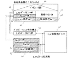
図3には、基地局装置51の内部の構成に関して、プロトコルスタックの構成例及びバックボーンLAN52側の構成例を示してある。
同図に示した基地局装置51のプロトコルスタックでは、無線リンクレイヤ61と無線物理レイヤ62から構成される無線側プロトコルレイヤと、LANデータリンクレイヤ63とMAC(Media Access Control)レイヤ64とLAN物理レイヤ65から構成されるLAN側プロトコルレイヤと、無線側プロトコルレイヤの無線リンクレイヤ61とLAN側プロトコルレイヤのLANデータリンクレイヤ63とをインタフェースするインタフェース部66が設けられている。
【0007】
また、同図に示したバックボーン側の構成では、MACレイヤ64はDMAC(Direct Memory Access Controller)71とMAC制御部72から構成されており、また、LANの送受信バッファ67が備えられている。
また、通常、無線物理レイヤ62やMACレイヤ64やLAN物理レイヤ65(図中で線模様を付したもの)はハードウエアにより構成され、無線リンクレイヤ61やLANデータリンクレイヤ63やインタフェース部66はソフトウエアのモジュールとして実装される。
【0008】
なお、本例では、無線通信の管理や制御を行う部分を無線リンクレイヤ61と言っており、バックボーンLAN52側のデータ処理を行う部分をLANデータリンクレイヤ63と言っている。
また、インタフェース部66では、無線リンクレイヤ61とLANデータリンクレイヤ63との間のデータ転送に必要な情報のやり取りが行われる。
【0009】
図4には、バックボーンLAN52側から無線通信(加入者局装置53a、53b)側への通信に関して、LANデータリンクレイヤ63と無線リンクレイヤ61との間のインタフェース部分の構成例を示してある。
同図に示した構成では、LANデータリンクレイヤ63と無線リンクレイヤ61との間に、複数の加入者局装置(“加入者局装置1”、“加入者局装置2”、・・・)のそれぞれに宛てられた信号をそれぞれの加入者局装置毎に格納するための複数のキュー部(各加入者局宛キュー部)Q1、Q2、・・・と、全ての加入者局装置に宛てられた信号を格納するためのキュー部(全加入者局宛キュー部)QAが設けられている。
【0010】
このように、本例では、インタフェース部66において、例えば先入れ先出し方式(FIFO:First In First Out)のキューを用いることにより、LANのフレームが非同期に発生するバックボーンLAN52側の制御と、通常は同期的にデータの送信(転送)が行われる無線側の制御との間の制御上の違いを吸収することが図られている。
【0011】
また、同図の例では、上述のように基地局装置51から加入者局装置53a、53bへのデータ送信(下り通信)に着目した場合を示してあり、通常は、本例のように、キューとしては、各加入者局装置毎に用意されるキューと、全ての加入者局装置に対して一斉に送信する必要があるブロードキャストデータやマルチキャストデータといったデータのために用意されるキューとで、複数個のキューが存在する。
【0012】
上記図3や上記図4に示されるように、基地局装置51の内部の制御構成では、バックボーンLAN52側のデータ処理を行う部分と、無線通信の管理や制御を行う部分との2つの部分に分けて捉えることが可能である。
【0013】
上記のような基地局装置51において、LANインタフェースでLANフレームの受信が発生した場合には、MACレイヤ64内のDMAC71が、受信したLANフレームをシステムメモリの領域(エリア)上に割り当てられたLANの受信バッファの空き領域へ転送し、その転送先のアドレスや転送サイズなどの情報をシステムメモリの領域上に割り当てられたディスクリプタ領域に書き込む。
【0014】
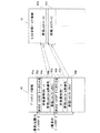
図5には、ディスクリプタ領域82の構成例を示してあり、また、LAN受信バッファ領域81の構成例を示してある。
同図に示したディスクリプタ領域82では、1番目(先頭)のディスクリプタ、2番目のディスクリプタ、・・・のそれぞれについて、次のディスクリプタへのリンク先91a、91bと、受信通知用ビット92a、92bと、受信LANフレーム格納先93a、93bと、受信LANフレームサイズ94a、94bが格納されている。また、同図では、図示を省略したが、受信ステータスが格納される場合もある。
【0015】
なお、ここでは、通常において用いられるディスクリプタ領域のフォーマットの詳細を示したが、このようなフォーマットは例えば個々のMACレイヤ64に実装されるDMAC71の仕様により決定される。
【0016】
それぞれのディスクリプタでは、次のディスクリプタへのリンク先91a、91bとしては、当該それぞれのディスクリプタの次に参照すべきディスクリプタの先頭アドレスが格納され、具体的には、1番目のディスクリプタにおける次のディスクリプタへのリンク先91aでは2番目のディスクリプタの先頭アドレスが格納され、2番目以降のディスクリプタについても同様である。
なお、通常、先頭のディスクリプタのアドレスは、システムの初期化時にDMAC71が具備する専用のレジスタにより通知される。
【0017】
また、受信通知用ビット92a、92bとしては、LANフレームの受信が発生して受信LANフレームをLAN受信バッファ領域81へ転送することが完了したことをDMAC71からシステム側(LANデータリンクレイヤ63)に通知するための情報が格納される。
【0018】
また、受信LANフレーム格納先93a、93bとしては、受信LANフレームを格納した先となるLAN受信バッファ領域81のアドレスが格納される。
また、受信LANフレームサイズ94a、94bとしては、受信LANフレームのサイズが格納される。
【0019】
具体的には、1番目のディスクリプタについては、受信LANフレームサイズ94aにより特定されるサイズを有する受信LANフレームF11が受信LANフレーム格納先93aにより特定されるアドレスからLAN受信バッファ領域81に格納され、2番目のディスクリプタについては同様に受信LANフレームF12が格納され、3番目以降のディスクリプタについても同様である。
【0020】
また、受信ステータスとしては、受信LANフレームの受信ステータスが格納され、具体的には、例えば、エラーの有無や、エラーが有る場合におけるエラーの内容などの情報が格納される。
【0021】
図6には、DMAC71と、MAC制御部72と、CAM(Contents AddressMemory)101と、それぞれの加入者局装置(“加入者局装置1”、“加入者局装置2”、・・・)毎に設けられて無線送信用のバッファを構成するメモリブロック(加入者局用メモリブロック)111a〜111c、112a〜112cを示してある。なお、無線送信用のバッファは、通常、複数のメモリブロック111a〜111c、112a〜112cから構成される。
【0022】
ここで、CAM101は、検索キーとなるデータをアドレス指定した場合に当該キーに対するストアデータを高速で読み出すことが可能な連想メモリデバイスである。本例では、検索キーとしては下り通信のLANフレームの宛先となるMACアドレスが用いられ、ストアデータとしては下り通信のLANフレームの送信先となる加入者局装置の番号(加入者局番号)が用いられる。
【0023】
なお、MACアドレスとしては、例えば、それぞれの加入者局装置53a、53bに収容されるそれぞれの加入者端末装置54a、54b、55a、55bのMACアドレスが用いられる。
【0024】
また、本例では、加入者局装置53、53bから基地局装置51へのデータ送信(上り通信)が発生した際に、上りのLANフレームの送信元となるMACアドレスをCAM101のアドレスに指定して、当該LANフレームの送信元となる加入者局番号をCAM101に蓄積(ストア)していくことが行われる。これにより、下りのLANフレームを受信した際に、その宛先となるMACアドレスがCAM101にストア済み(学習済み)であれば、その送信先となる加入者局装置(加入者局番号)を特定することが可能となる。
【0025】
次に、上記図6を参照して、MAC制御部72やLANデータリンクレイヤ63により行われる処理の一例を示す。
MAC制御部72は、フィルタリング処理として、CAM101を用いて、受信LANフレームをLAN受信バッファ領域81へ転送するか否かを判定する(処理T1)。
【0026】
具体的には、MAC制御部72は、下りのLANフレームの宛先となるMACアドレスがCAM101にストアされていない(未学習の)宛先である場合には、例えば、当該LANフレームを全ての加入者局装置に対して送信する処理(フラッディング)或いは当該LANフレームを廃棄する処理のいずれかを行う構成がとられる。
【0027】
通常のブリッジ装置の場合には、フラッディングが採用されるが、無線アクセスシステムの場合には、通常、無線帯域を無駄に消費しない目的のため、廃棄する処理を行う方針がとられている。
そこで、本例では、MAC制御部72は、下りのLANフレームの宛先となるMACアドレスがCAM101にストアされていない(未学習の)宛先である場合には、当該LANフレームを廃棄する。
【0028】
LANデータリンクレイヤ63は、現在において対象となるディスクリプタ(カレント受信ディスクリプタ)内の受信通知用ビット92a、92bをチェックして、LANフレームの受信を検出する。そして、LANデータリンクレイヤ63は、受信したLANフレームに対して最初に行う処理として、当該受信LANフレームの宛先(転送先)に対応する加入者局装置53a、53bを判別する(処理T2)。通常、この判別処理を行うために、CAM101のデバイスが用いられ、つまり、CAM101の記憶内容により、受信LANフレームの宛先となるMACアドレスに対して加入者局番号が特定される。
【0029】
次に、LANデータリンクレイヤ63は、受信LANフレームを無線送信用のバッファへ転送する。具体的には、LANデータリンクレイヤ63は、加入者局装置毎に用意されたメモリブロック111a〜111c、112a〜112cへ受信LANフレームを、例えば連結或いは分割して、格納する(処理T3)。
【0030】
ここで、通常、無線送信用のバッファは複数のメモリブロック111a〜111c、112a〜112cから構成され、個々のメモリブロック111a〜111c、112a〜112c内に転送されたデータは無線媒体上のデータ送信(転送)スロットに載せられて加入者局装置53a、53b側へ送信(転送)される。
【0031】
また、通常、データ送信スロットとしては固定時間の割り当てが為されるものが用いられるため、メモリブロック111a〜111c、112a〜112cとしては固定サイズのものが用いられる。これに対して、受信LANフレームは可変長であるため、例えば、1つのメモリブロック(つまり、1つのデータ送信スロット)に1つのLANフレームだけを載せて送信する構成では、無線区間におけるデータ送信効率が悪くなる場合がある。このため、LANデータリンクレイヤ63は、それぞれの加入者局装置毎に確保したメモリブロック111a〜111c、112a〜112cに対して、例えば受信LANフレームを連結或いは分割した形で転送していく。
【0032】
上記のようにしてLANフレームの転送が完了したメモリブロック111a〜111c、112a〜112cは、無線リンクレイヤ61へ渡される。これは、インタフェース部66に設けられる各送信先(各加入者局装置)毎に存在するキューにより通知される。
この後、無線リンクレイヤ61は、個々の送信先(加入者局装置)毎にデータ送信スロットを割り当て、データ送信スロットとメモリブロック111a〜111c、112a〜112c上のデータ(転送データ)とのリンクを形成する。
【0033】
なお、本発明に関する先行技術文献として、加入者無線アクセスシステムにおけるMACレイヤとLANデータリンクレイヤとの転送処理に関して先行技術文献を探したが、適当なものが見つからなかったため、本明細書では先行技術文献情報を記載していない。
【0034】
【発明が解決しようとする課題】
しかしながら、上記図2〜上記図6を参照して説明したような従来の基地局装置51では、MAC制御部72やLANデータリンクレイヤ63によりCAM101を用いて行われる処理が冗長であったため、処理の効率が悪いといった不具合があった。
【0035】
具体的には、上記したCAM101は、上述のように、LANデータリンクレイヤ63により受信LANフレームの送信先を判別するために使用されるほかに、MAC制御部72により受信LANフレームをフィルタリングするためにも使用される。このようなフィルタリングを行って宛先不明の受信LANフレームを廃棄する方針を採用する場合には、受信LANフレームをMAC制御部72のレベルで廃棄することにより、LAN受信バッファ領域81が無駄に消費されてしまうことを防ぐことができる。
【0036】
しかしながら、この場合、MAC制御部72におけるCAM101の参照結果はフィルタリングの目的だけに使用されるため、その後において、LANデータリンクレイヤ63により同一の受信LANフレームに対してその送信先を判別するために再度CAM101にアクセスしなければならず、これが冗長な処理となってしまっていた。
【0037】
本発明は、このような従来の課題を解決するために為されたもので、受信信号に含まれる宛先識別情報に基づいて受信信号を廃棄するか否かなどを判定する処理及び受信信号を対応する送信先に対して送信する処理を行うに際して、このような処理を効率化することができる通信装置を提供することを目的とする。
【0038】
【課題を解決するための手段】
上記目的を達成するため、本発明に係る通信装置では、次のような構成により、宛先を識別する宛先識別情報を含む信号を受信し、受信した信号を当該信号に含まれる宛先識別情報に対応する送信先に対して送信する。
すなわち、宛先送信先対応情報記憶手段が、宛先識別情報と送信先を識別する送信先識別情報との対応に関する情報を記憶する。また、受信される信号に対応する送信先識別情報を記憶する送信先識別情報記憶手段を備える。
そして、受信信号送信判定手段が、宛先送信先対応情報記憶手段の記憶内容及び受信される信号に含まれる宛先識別情報に基づいて、受信信号の送信処理に関する判定を行うとともに、例えば受信信号に含まれる宛先識別情報に対応する送信先識別情報を特定することが可能な場合には、受信信号に含まれる宛先識別情報に対応する送信先識別情報を送信先識別情報記憶手段に記憶させる。また、受信信号処理手段が、受信信号送信判定手段による判定後の受信信号を送信先識別情報記憶手段の記憶内容に基づく送信先識別情報に対応する送信先に対して送信するための処理を行う。
【0039】
従って、受信信号送信判定手段により受信信号に対応する送信先識別情報が宛先送信先対応情報記憶手段の記憶内容に基づいて特定されて送信先識別情報記憶手段に記憶させられ、その後、受信信号処理手段により当該送信先識別情報記憶手段の記憶内容に基づく処理が行われるため、例えば、受信信号に含まれる宛先識別情報に基づいて受信信号を廃棄するか否かなどを判定する処理及び受信信号を対応する送信先に対して送信する処理を行うに際して、このような処理を効率化することができる。
【0040】
具体的には、従来では、例えば受信信号送信判定手段と受信信号処理手段がそれぞれ独立して宛先送信先対応情報記憶手段の記憶内容を参照するような構成であったが、本発明では、受信信号送信判定手段が宛先送信先対応情報記憶手段の記憶内容を参照した結果を受信信号処理手段が参照するような構成であるため、処理の効率化が図られる。
【0041】
ここで、本発明に係る通信装置としては、種々なものに適用されてもよい。
また、宛先としては、種々なものが用いられてもよい。
また、宛先識別情報としては、種々な情報が用いられてもよい。
また、宛先識別情報を含む信号には、例えば、通信対象となるデータや、或いは制御のための情報が含まれる。
また、送信先としては、種々なものが用いられてもよい。
また、送信先識別情報としては、種々な情報が用いられてもよい。
【0042】
一例として、送信先と宛先とは異なるものとして、送信先として宛先を収容するものを用いることができ、この場合、本発明に係る通信装置から送信される信号は、送信先により受信された後に、当該送信先から宛先に対して送信される。
他の例として、送信先と宛先とは同じものであるとして、当該同じものに宛先識別情報と送信先識別情報といった異なる識別情報が設定されているような態様を用いることも可能であり、この場合、本発明に係る通信装置から送信される信号は、送信先により受信されることにより、宛先により受信されることとなる。
【0043】
また、信号を受信する態様や、信号を送信する態様としては、それぞれ、有線を用いて通信を行う態様が用いられてもよく、或いは、無線を用いて通信を行う態様が用いられてもよい。
一例として、有線を用いて信号を受信して、無線を用いて受信信号を送信するような態様を用いることができる。
【0044】
また、宛先識別情報と送信先識別情報との対応に関する情報としては、種々な情報が用いられてもよく、例えば、当該対応が特定されるような情報が用いられる。
また、送信先識別情報記憶手段は、例えば、各受信信号毎に送信先識別情報を記憶し、或いは、各送信先毎に受信信号若しくは受信信号を特定する情報を記憶する。
【0045】
また、受信信号の送信処理に関する判定としては、種々な判定が行われてもよく、例えば、受信信号を廃棄するか又は廃棄しないかを判定することつまり受信信号を送信しないか又は送信するかを判定することや、或いは、受信信号を全ての送信先に対して送信するか又は個別の送信先に対して送信するかを判定することなどが行われる。
また、受信信号送信判定手段による判定後の受信信号としては、例えば、受信信号を廃棄するか又は廃棄しないかが判定される場合には、廃棄せずに送信することが判定された受信信号が用いられ、廃棄された受信信号は用いられない。
【0046】
また、受信信号を送信先識別情報記憶手段の記憶内容に基づく送信先識別情報に対応する送信先に対して送信するための処理としては、種々な処理が用いられてもよく、例えば、送信のための前段の処理が用いられてもよく、或いは、送信の処理が用いられてもよい。
また、受信信号について送信先識別情報記憶手段の記憶内容に基づく送信先識別情報に対応する送信先としては、当該受信信号に含まれる宛先識別情報に対応する送信先識別情報に対応する送信先が用いられる。
【0047】
なお、本発明に係る通信装置では、送信元から送信される信号を受信して、当該受信した信号を送信先に対して送信する通信に着目しているが、例えば、当該送信先から送信される信号を受信して、当該受信した信号を当該送信元に対して送信する通信が共に行われてもよく、つまり、必ずしも一方向の通信のみが行われなくともよく、双方向の通信が行われてもよい。
【0048】
また、本発明に係る通信装置では、一構成例として、次のような構成とした。
すなわち、本発明に係る通信装置は、受信側のプロトコルレイヤと、送信側のプロトコルレイヤを有する。
また、受信側のプロトコルレイヤには、受信信号処理手段を備えた第1のレイヤと、受信信号送信判定手段を備えた第2のレイヤが含まれる。
また、第1のレイヤはソフトウエアを用いて構成され、第2のレイヤはハードウエアを用いて構成される。
【0049】
従って、例えば、受信側のプロトコルレイヤにおいてハードウエアを用いて構成される第2のレイヤからソフトウエアを用いて構成される第1のレイヤへ受信信号を渡して、当該第1のレイヤから送信側のプロトコルレイヤへ当該受信信号を渡す(転送する)処理に関して、処理の効率化を図ることができる。
【0050】
ここで、受信側のプロトコルレイヤや、送信側のプロトコルレイヤとしては、それぞれ種々なものが用いられてもよい。
また、第1のレイヤや、第2のレイヤとしては、それぞれ種々なものが用いられてもよい。
【0051】
また、本発明に係る通信装置では、一構成例として、次のような構成とした。
すなわち、本発明に係る通信装置は基地局装置であり、送信先は当該基地局装置により収容される通信局装置であり、宛先識別情報により識別される宛先は当該通信局装置により収容される通信端末装置である。
また、第1のレイヤはデータリンクレイヤであり、第2のレイヤはMACレイヤである。
また、宛先送信先対応情報記憶手段及び送信先識別情報記憶手段は、それぞれメモリを用いて構成される。
また、受信信号送信判定手段は、受信信号の送信処理に関する判定として受信信号を廃棄するか否かを判定し、少なくとも受信信号を非廃棄とする場合(つまり、廃棄しない場合)に当該受信信号に含まれる宛先識別情報に対応する送信先識別情報を送信先識別情報記憶手段に記憶させる。
【0052】
従って、MACレイヤにおいて受信信号を廃棄するか否かを判定し、データリンクレイヤにおいて受信信号を送信先に対して送信するための処理を行うに際して、MACレイヤにおいて取得される宛先送信先対応情報記憶手段の記憶内容の参照結果をデータリンクレイヤにより利用するため、処理の効率化を図ることができる。
【0053】
ここで、基地局装置や、通信局装置や、通信端末装置としては、それぞれ種々なものが用いられてもよい。
また、基地局装置により収容される通信局装置としては、例えば、基地局装置と無線或いは有線により通信可能に接続される。
また、基地局装置により収容される通信局装置の数としては、例えば1又は複数の種々な数であってもよい。
【0054】
また、通信局装置により収容される通信端末装置としては、例えば、通信局装置と有線或いは無線により通信可能に接続される。
また、通信局装置により収容される通信端末装置の数としては、例えば1又は複数の種々な数であってもよい。
また、メモリとしては、種々なものが用いられてもよい。
【0055】
また、少なくとも受信信号を非廃棄とする場合に当該受信信号に含まれる宛先識別情報に対応する送信先識別情報を送信先識別情報記憶手段に記憶させる態様としては、例えば、受信信号を非廃棄とする場合にのみ当該記憶させる処理を行う態様が用いられてもよく、或いは、受信信号を非廃棄とする場合を含む全ての場合又は所定の場合に当該記憶させる処理を行うような態様が用いられてもよい。
【0056】
なお、受信信号の送信処理に関する判定として、受信信号を全ての送信先に対して送信するか又は個別の送信先に対して送信するかを判定することが行われる場合には、例えば、全ての受信信号について、当該判定結果に基づいて、全ての送信先を指定する送信先識別情報又は個別の送信先を指定する送信先識別情報を送信先識別情報記憶手段に記憶させる態様などを用いることができる。
【0057】
以下で、更に、本発明の構成例を示す。
本発明に係る通信装置では、基地局装置として構成される場合に、一構成例として、受信される信号は、LANのフレームの信号であり、例えば他の基地局装置などからバックボーンのLANを介して受信される。
また、宛先識別情報は宛先となる通信端末装置に設定されたMACアドレスの情報であり、送信先識別情報は基地局装置により収容される各通信局装置を識別する通信局番号の情報である。
【0058】
ここで、LANのフレームとしては、種々なものが用いられてもよい。
また、バックボーンのLANとしては、種々なものが用いられてもよい。
また、MACアドレスの情報としては、種々な情報が用いられてもよい。
また、通信局番号の情報としては、種々な情報が用いられてもよい。
【0059】
また、本発明に係る通信装置では、一構成例として、宛先送信先対応情報記憶手段は、連想メモリデバイスを用いて構成され、宛先識別情報と送信先識別情報との対応を記憶し、指定される宛先識別情報に対応する送信先識別情報を特定する。具体例として、宛先送信先対応情報記憶手段は、外部から入力される宛先識別情報をキーとして当該キーに対応する送信先識別情報を外部へ出力する。
ここで、連想メモリデバイスとしては、種々なものが用いられてもよい。
【0060】
また、本発明に係る通信装置では、送信先との間で双方向通信が行われる構成において、一構成例として、送信先から送信される信号を受信した場合に、当該送信先の識別情報を送信先識別情報とみなすとともに当該受信信号に含まれる発信元の識別情報を宛先識別情報とみなして、当該宛先識別情報と当該送信先識別情報との対応に関する情報を宛先送信先対応情報記憶手段に記憶させる宛先送信先対応情報記憶処理手段を備える。
従って、送信先から受信される信号に基づいて、宛先送信先対応情報記憶手段に情報を登録していくことができる。
【0061】
また、本発明に係る通信装置では、一構成例として、受信信号送信判定手段は、受信される信号に含まれる宛先識別情報或いは当該宛先識別情報に対応する送信先識別情報が宛先送信先対応情報記憶手段に記憶されているか否かを判定し、当該宛先識別情報或いは当該宛先識別情報に対応する送信先識別情報が宛先送信先対応情報記憶手段に非記憶である場合(つまり、記憶されていない場合)には当該受信信号を廃棄することを判定し、少なくとも当該受信信号を非廃棄とする場合には当該受信信号に含まれる宛先識別情報に対応して宛先送信先対応情報記憶手段に記憶された送信先識別情報を送信先識別情報記憶手段に記憶させる。
【0062】
また、本発明に係る通信装置では、他の構成例として、受信信号送信判定手段は、受信される信号に含まれる宛先識別情報或いは当該宛先識別情報に対応する送信先識別情報が宛先送信先対応情報記憶手段に記憶されているか否かを判定し、当該宛先識別情報或いは当該宛先識別情報に対応する送信先識別情報が宛先送信先対応情報記憶手段に非記憶である場合(つまり、記憶されていない場合)には当該受信信号を全ての送信先に対して送信することを判定し、少なくとも当該宛先識別情報或いは当該宛先識別情報に対応する送信先識別情報が宛先送信先対応情報記憶手段に記憶されている場合には、当該宛先識別情報に対応して宛先送信先対応情報記憶手段に記憶された送信先識別情報を送信先識別情報記憶手段に記憶させる。
【0063】
また、本発明に係る通信装置では、受信側のプロトコルレイヤと送信側のプロトコルレイヤを有する構成において、一構成例として、受信側のプロトコルレイヤの第1のレイヤでは、受信信号処理手段は、受信信号送信判定手段による判定後の受信信号を送信先識別情報記憶手段の記憶内容に基づく送信先識別情報に対応する送信先に対して送信するための処理として、当該受信信号を送信側のプロトコルレイヤへ渡す処理を行う。具体例として、送信側のプロトコルレイヤでは各送信先毎に対応する複数のバッファを備えており、第1のレイヤの受信信号処理手段は、受信信号送信判定手段による判定後の受信信号を送信先識別情報記憶手段の記憶内容に基づく送信先識別情報に対応する送信先に対応するバッファに格納する。
【0064】
また、本発明に係る通信装置では、一構成例として、送信先識別情報記憶手段は、システムメモリを用いて構成される。具体例として、送信先識別情報記憶手段は、システムメモリに設けられたディスクリプタ領域を用いて構成され、受信信号を特定する情報と、当該受信信号に対応する送信先識別情報とを対応付けて記憶する。
【0065】
ここで、システムメモリや、ディスクリプタ領域としては、それぞれ種々なものが用いられてもよい。
また、受信信号を特定する情報としては、例えば、受信信号自体の情報や、或いは、受信信号を記憶する領域のアドレスの情報などを用いることができる。一構成例として、システムメモリには受信信号を一時的に格納する受信信号バッファ手段が設けられ、ディスクリプタ領域において受信信号を特定する情報として当該受信信号が受信信号バッファ手段に格納されたアドレスの情報が用いられる。
【0066】
また、本発明に係る通信装置では、受信側のプロトコルレイヤと送信側のプロトコルレイヤを有する構成において、一構成例として、受信側のプロトコルレイヤでは、MACレイヤである第2のレイヤは、MAC制御部とDMACを備える。
また、MAC制御部は、受信信号を入力してDMACへ出力するMAC制御部受信信号入出力手段と、受信信号に含まれる宛先識別情報或いは当該宛先識別情報に対応する送信先識別情報が宛先送信先対応情報記憶手段に記憶されているか否かを判定する宛先識別情報記憶判定手段と、受信信号に含まれる宛先識別情報或いは当該宛先識別情報に対応する送信先識別情報が宛先送信先対応情報記憶手段に非記憶である場合(つまり、記憶されていない場合)には当該受信信号を廃棄することを判定して当該受信信号を廃棄する受信信号廃棄手段と、少なくとも受信信号を非廃棄とする場合には当該受信信号に含まれる宛先識別情報に対応して宛先送信先対応情報記憶手段に記憶された送信先識別情報を読み出して記憶するMAC制御部送信先識別情報記憶手段とを備える。
また、DMACは、MAC制御部から受信信号を入力してシステムメモリへ出力するDMAC受信信号入出力手段と、MAC制御部送信先識別情報記憶手段に記憶された送信先識別情報を入力してシステムメモリへ出力する送信先識別情報入出力手段とを備える。
【0067】
ここで、MAC制御部のMAC制御部受信信号入出力手段は、例えば、物理レイヤから受信信号を入力する。
また、DMACは、例えば、送信先識別情報入出力手段により入出力される送信先識別情報を記憶するDMAC送信先識別情報記憶手段を備える。
【0068】
また、本発明に係る通信装置では、一構成例として、当該通信装置は加入者無線アクセスシステムの基地局装置であり、送信先は当該加入者無線アクセスシステムの加入者局装置であり、宛先識別情報により識別される宛先は当該加入者無線アクセスシステムの加入者端末装置である。
ここで、加入者無線アクセスシステムや、当該システムに備えられる基地局装置や加入者局装置や加入者端末装置としては、種々なものが用いられてもよく、また、それぞれの装置の数としては、種々な数が用いられてもよい。
【0069】
【発明の実施の形態】
本発明に係る一実施例を図面を参照して説明する。
本例では、上記図2〜上記図6を参照して説明したような加入者無線アクセスシステムの基地局装置に本発明を適用した場合を示す。このため、本例では、上記図2〜上記図6を参照して説明したのと同様な構成や動作については説明を省略或いは簡略化し、異なる構成や動作について詳しく説明する。
【0070】
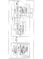
図1には、本例の基地局装置に備えられたMACレイヤ1やシステムメモリ2やCAM3に関する構成例を示してある。
MACレイヤ1には、MAC制御部11と、DMAC12と、MAC制御部11とDMAC12とをインタフェースする複数のバスインタフェース14a〜14cから構成されるバスインタフェース群14が備えられている。
また、MACレイヤ1とLAN物理レイヤ(図示せず)との間には、これらをインタフェースするバスインタフェース群(物理層バスインタフェース群)13が備えられている。
【0071】
MAC制御部11には、LANフレーム送受信FIFO21と、MACコントロール/ステータスレジスタ部22と、CAM参照結果格納レジスタ23と、CAM参照制御部24が備えられている。
DMAC12には、LANフレーム送受信FIFO25と、DMACコントロール/ステータスレジスタ部26と、CAM参照結果保持部27が備えられている。
【0072】
また、MAC制御部11のLANフレーム送受信FIFO21とDMAC12のLANフレーム送受信FIFO25とがバスインタフェース14aにより接続されており、MAC制御部11のMACコントロール/ステータスレジスタ部22とDMAC12のDMACコントロール/ステータスレジスタ部26とがバスインタフェース14bにより接続されており、MAC制御部11のCAM参照結果格納レジスタ23とDMAC12のCAM参照結果保持部27とがバスインタフェース14bにより接続されている。
【0073】
システムメモリ2には、受信LANフレームF1を格納するLAN受信バッファ31と、ディスクリプタ領域32が設けられている。
ディスクリプタ領域32には、例えば1番目、2番目、・・・といった複数のディスクリプタについて、それぞれ、次のディスクリプタへのリンク先41と、受信通知用ビット42と、受信LANフレーム格納先43と、受信LANフレームサイズ44と、受信ステータス45と、CAM参照結果46が設けられている。
【0074】
また、MACレイヤ1とシステムメモリ2との間には、これらをインタフェースするバスインタフェース群(システムメモリバスインタフェース群)15が備えられている。
また、CAM3は、MAC制御部11のCAM参照制御部24により当該CAM3の記憶内容を参照することが可能な構成で、備えられている。なお、本例の図1では、MACレイヤ1の外部にCAM3を備えた構成を示したが、例えば、MACレイヤ1の内部やMAC制御部11の内部などの種々なところにCAM3が備えられてもよい。
【0075】
次に、上記図1に示したそれぞれの構成部により行われる動作の例などを示す。
MACレイヤ1のモジュールは、LANデータリンクレイヤ(図示せず)の下位層に位置している。
物理層バスインタフェース群13は、例えばMII(Machine Independent Interface)などを用いて構成され、物理層(LAN物理レイヤ)とMACレイヤ1とを接続してLANフレームの送受信を可能とする。
【0076】
MAC制御部11のLANフレーム送受信FIFO21は、送受信するLANフレームを一時的に格納する。
MAC制御部11のMACコントロール/ステータスレジスタ部22は、制御用の情報を格納するMACコントロールレジスタ群と、送受信のステータスを格納するMACステータスレジスタ群を備えている。
【0077】
MAC制御部11のCAM参照制御部24は、外部(又は内部)のCAM3を参照する処理を実行する。
MAC制御部11のCAM参照結果格納レジスタ23は、CAM3の参照結果を格納する。
MAC制御部11とDMAC12との間のバスインタフェース群14は、MAC制御部11とDMAC12とを接続してLANフレームの転送などを可能とする。
【0078】
DMAC12のLANフレーム送受信FIFO25は、送受信するLANフレームを一時的に格納する。
DMAC12のDMACコントロール/ステータスレジスタ部26は、制御用の情報を格納するDMACコントロールレジスタ群と、転送のステータスやMACステータスレジスタ群の格納内容を格納するDMACステータスレジスタ群を備えている。
DMAC12のCAM参照結果保持部27は、MAC制御部11のCAM参照結果格納レジスタ23の格納内容を一時的に保持する。
【0079】
システムメモリバスインタフェース群15は、MACレイヤ1とシステムメモリ2とを接続してLANフレームの転送などを可能とする。
システムメモリ2のディスクリプタ領域32に設けられるCAM参照結果46は、MACレイヤ1のDMAC12から入力されるCAM3の参照結果を格納する。
また、システムメモリ2のディスクリプタ領域32に設けられる先頭のディスクリプタのアドレスは、例えば、システムの初期化時に、DMAC12が具備する専用のレジスタ26により通知される。
【0080】
なお、本例では、上記した物理層バスインタフェース群13やMACレイヤ1内のバスインタフェース群14やシステムメモリバスインタフェース群15がそれぞれのモジュールの間を接続することにより、物理層とLANデータリンクレイヤとの間でMACレイヤ1を介してLANフレームの送受信などを行うことを可能としている。
【0081】
次に、上記図1に示した構成部により行われる全体的な処理の一例を示す。
なお、本例では、物理層からMACレイヤ1を介してLANデータリンクレイヤへLANフレームを転送する処理つまり基地局装置がバックボーンLANから受信されるLANフレームを加入者局装置に対して無線送信する下り通信が行われる場合の処理について示すが、基地局装置では、例えば、LANデータリンクレイヤからMACレイヤ1を介して物理層へLANフレームを転送する処理つまり基地局装置が加入者局装置から無線受信されるLANフレームをバックボーンLANへ送信する上り通信が行われる場合の処理についても実行される。
【0082】
まず、MAC制御部11では、物理層からLANフレームを受信した際に、CAM参照制御部24が当該LANフレームの宛先となるMACアドレスをキーとして、CAM3を参照する。
この参照の結果、当該LANフレームに対するCAM3のエントリである送信先(転送先)の加入者局番号が存在しない場合には、つまり、当該LANフレームに含まれる宛先となるMACアドレス或いは当該MACアドレスに対応する加入者局番号がCAM3に登録されていない場合には、受信した当該LANフレームをMAC制御部11がその内部で廃棄し、この場合には、当該LANフレームはDMAC12側へは転送されない。
【0083】
一方、上記の参照の結果、当該LANフレームに対するCAM3のエントリである送信先(転送先)の加入者局番号が存在する場合には、つまり、当該LANフレームに含まれる宛先となるMACアドレスに対応する加入者局番号がCAM3に登録されている場合には、CAM参照制御部24が当該エントリの内容つまり送信先となる当該加入者局番号をCAM参照結果格納レジスタ24に格納する。
【0084】
また、この場合には、続いて、以下の処理が行われる。
すなわち、DMAC12側において、MAC制御部11から受信された当該LANフレームを読み出し、読み出した当該LANフレームを、LANフレーム受信FIFO25を経由して、システムメモリ2に設けられたLAN受信バッファ31の空きエリアへ転送する。
【0085】
更に、DMAC12では、当該LANフレームの受信ステータスを、MACステータスレジスタ22からDMACステータスレジスタ26を経由して、システムメモリ2に設けられたディスクリプタ領域32の受信ステータス45に書き込み、これと同時に、MAC制御部11のCAM参照結果格納レジスタ23に格納されたデータを、CAM参照結果保持部27を経由して、当該ディスクリプタ領域32のCAM参照結果46に書き込み、また、当該LANフレームの転送に関する他の情報についてもあわせて当該ディスクリプタ領域32に書き込む。
【0086】
次いで、システム側のLANデータリンクレイヤでは、LAN受信バッファ31に格納された受信LANフレームを当該LAN受信バッファ31から無線側の無線送信用バッファを構成するメモリブロックへ転送する処理を、ディスクリプタ領域32のCAM参照結果46を参照して当該受信LANフレームの送信先となる加入者局番号を特定して、当該特定した加入者局番号に対応したメモリブロックへ当該受信LANフレームを格納することにより行う。
【0087】
以上のように、本例の無線アクセスシステムに備えられる基地局装置では、LANデータリンクレイヤが、例えばMAC制御部11に続いて再度CAM3を参照することを行わずに、比較的にアクセスし易いシステムメモリ2に設けられたディスクリプタ領域32のCAM参照結果46を参照するだけで無線側へ転送するLANフレームの送信先(加入者局番号)を判別することができるため、例えば従来と比べて、LANデータリンクレイヤにおける受信LANフレーム転送処理の一部を軽減することができ、これにより、バックボーンLAN側のMACレイヤ11からLANデータリンクレイヤを介して無線側の無線リンクレイヤへの受信LANフレームの転送処理の高速化を図ることができる。
【0088】
なお、一般に、CAM3のデバイスはテーブルの高速検索を可能としているが、それでも、ディスクリプタ領域32を参照する処理(メモリリードの処理)の方が圧倒的に短時間で済む。このため、本例のように、従来においてMACレイヤ1とLANデータリンクレイヤとの両方から行われていたCAM3ヘのアクセス処理をMACレイヤ1側からのアクセスのみにまとめて、CAM3を2回重ねてアクセスする冗長性を排除することにより、LANデータリンクレイヤにおけるLANフレーム毎の処理の一部を軽減することができ、これにより、LANデータリンクレイヤにおけるデータ転送処理の高速化を図ることができる。
【0089】
また、一般に、無線アクセスシステムなどでは、LANデータリンクレイヤはソフトウエアにより実装されるスイッチモジュールとして構成されるため、LANフレーム毎の処理量や処理時間は可能な限りで少なくすることが望ましく、特に、本発明を適用するのに好適である。
【0090】
なお、本発明に係る通信装置を適用した本例の基地局装置では、宛先として加入者端末装置が用いられており、送信先として加入者局装置が用いられており、宛先識別情報としてMACアドレスの情報が用いられており、送信先識別情報として加入者局番号の情報が用いられており、受信して送信する信号としてLANフレームの信号が用いられている。
【0091】
また、本例の基地局装置では、LAN側から無線側へLANフレームを転送する処理に関して、LAN側のプロトコルレイヤにより受信側のプロトコルレイヤが構成されており、無線側のプロトコルレイヤにより送信側プロトコルレイヤが構成されている。
【0092】
また、本例の基地局装置では、CAM3の機能により宛先送信先対応情報記憶手段が構成されており、ディスクリプタ領域32に情報を記憶する機能により送信先識別情報記憶手段が構成されており、MACレイヤ1の機能により受信信号送信判定手段が構成されており、LANデータリンクレイヤの機能により受信信号処理手段が構成されており、LAN受信バッファ31の機能により受信信号バッファ手段が構成されている。
【0093】
また、本例の基地局装置に備えられたMAC制御部11では、LANフレーム送受信FIFO21の機能によりMAC制御部受信信号入出力手段が構成されており、CAM参照制御部24の機能により宛先識別情報記憶判定手段が構成されており、CAM参照制御部24などの機能により受信信号廃棄手段が構成されており、CAM参照制御部24やCAM参照結果格納レジスタ23の機能によりMAC制御部送信先識別情報記憶手段が構成されている。
また、本例の基地局装置に備えられたDMAC12では、LANフレーム送受信FIFO25の機能によりDMAC受信信号入出力手段が構成されており、CAM参照結果保持部27などの機能により送信先識別情報入出力手段が構成されている。
【0094】
ここで、本発明に係る通信装置や通信システムなどの構成としては、必ずしも以上に示したものに限られず、種々な構成が用いられてもよい。なお、本発明は、例えば本発明に係る処理を実行する方法或いは方式や、このような方法や方式を実現するためのプログラムなどとして提供することも可能である。
また、本発明の適用分野としては、必ずしも以上に示したものに限られず、本発明は、種々な分野に適用することが可能なものである。
【0095】
また、本発明に係る通信装置や通信システムなどにおいて行われる各種の処理としては、例えばプロセッサやメモリ等を備えたハードウエア資源においてプロセッサがROM(Read Only Memory)に格納された制御プログラムを実行することにより制御される構成が用いられてもよく、また、例えば当該処理を実行するための各機能手段が独立したハードウエア回路として構成されてもよい。
また、本発明は上記の制御プログラムを格納したフロッピー(登録商標)ディスクやCD(Compact Disc)−ROM等のコンピュータにより読み取り可能な記録媒体や当該プログラム(自体)として把握することもでき、当該制御プログラムを記録媒体からコンピュータに入力してプロセッサに実行させることにより、本発明に係る処理を遂行させることができる。
【0096】
【発明の効果】
以上説明したように、本発明に係る通信装置によると、宛先識別情報を含む信号を受信し、受信した信号を宛先識別情報に対応する送信先に対して送信するに際して、例えば、MACレイヤにおいて、宛先識別情報と送信先識別情報との対応を記憶する宛先送信先対応情報記憶部の記憶内容及び受信信号に含まれる宛先識別情報に基づいて、受信信号の送信処理に関する判定を行うとともに、受信信号に含まれる宛先識別情報に対応する送信先識別情報を特定することが可能な場合には当該送信先識別情報を送信先識別情報記憶部に記憶させ、その後、データリンクレイヤにおいて、当該判定後の受信信号を当該送信先識別情報記憶部の記憶内容に基づく送信先識別情報に対応する送信先に対して送信するための処理を行うようにしたため、このような一連の処理を効率化することができる。
【図面の簡単な説明】
【図1】本発明の一実施例に係る基地局装置に備えられたMACレイヤやシステムメモリやCAMに関する構成例を示す図である。
【図2】無線アクセスシステムの構成例を示す図である。
【図3】基地局装置のプロトコルスタックの構成例及びバックボーンLAN側の構成例を示す図である。
【図4】LANデータリンクレイヤと無線リンクレイヤとの間のインタフェース部分の構成例を示す図である。
【図5】ディスクリプタ領域の構成例を示す図である。
【図6】MAC制御部及びLANデータリンクレイヤにより行われる処理の一例を説明するための図である。
【符号の説明】
1、64・・MACレイヤ、 2・・システムメモリ、
3、101・・CAM、 11、72・・MAC制御部、
12、71・・DMAC、 13〜15・・バスインタフェース群、
14a〜14c・・バスインタフェース、
21、25・・LANフレーム送受信FIFO、
22、26・・コントロール/ステータスレジスタ部、
23・・CAM参照結果格納レジスタ、 24・・CAM参照制御部、
27・・CAM参照結果保持部、 31、81・・LAN受信バッファ、
32、82・・ディスクリプタ領域、
41、91a、91b・・次のディスクリプタへのリンク先、
42、92a、92b・・受信通知用ビット、
43、93a、93b・・受信LANフレーム格納先、
44、94a、94b・・受信LANフレームサイズ、
45・・受信ステータス、 46・・CAM参照結果、
F1、F11、F12・・LANフレーム、 51a、51b・・基地局装置、
52・・バックボーンLAN、 53a、53b・・加入者局装置、
54a、54b、55a、55b・・加入者端末装置、
61・・無線リンクレイヤ、 62・・無線物理レイヤ、
63・・LANデータリンクレイヤ、 65・・LAN物理レイヤ、
66・・インタフェース部、 67・・LAN送受信バッファ、
Q1、Q2、QA・・キュー部、
111a〜111c、112a〜112c・・メモリブロック、[0001]
TECHNICAL FIELD OF THE INVENTION
The present invention relates to a communication device that performs a process of determining whether to discard a received signal based on destination identification information included in the received signal and a process of transmitting the received signal to a corresponding destination, and in particular, The present invention relates to a communication device that makes such processing efficient.
[0002]
[Prior art]
FIG. 2 shows, as an example of a wireless access system called FWA (Fixed Wireless Access) or the like, a plurality of
[0003]
In the radio access system shown in the figure, communication is performed between a plurality of subscriber terminal devices 54a, 54b, 55a and 55b to which respective
[0004]
In such a wireless access system, for example, each of the subscriber terminal devices 54a, 54b, 55a, and 55b transmits their own (the subscriber terminal device) via the
[0005]
Next, a configuration example of the
Since the configurations of the respective
[0006]
FIG. 3 shows a configuration example of a protocol stack and a configuration example of the backbone LAN 52 with respect to the internal configuration of the base station device 51.
In the protocol stack of the base station device 51 shown in FIG. 3, a wireless side protocol layer including a
[0007]
In the configuration on the backbone side shown in the figure, the
Usually, the wireless
[0008]
In this example, a part that performs management and control of wireless communication is called a
The
[0009]
FIG. 4 shows a configuration example of an interface between the LAN
In the configuration shown in the figure, a plurality of subscriber station devices (“subscriber station device 1”, “
[0010]
As described above, in this example, the
[0011]
Also, in the example of FIG. 7, a case is shown in which attention is paid to data transmission (downlink communication) from the base station device 51 to the
[0012]
As shown in FIG. 3 and FIG. 4, the control configuration inside the base station device 51 has two parts, a part that performs data processing on the backbone LAN 52 side and a part that performs management and control of wireless communication. It is possible to catch them separately.
[0013]
In the above-described base station apparatus 51, when a LAN frame is received at the LAN interface, the
[0014]
FIG. 5 shows a configuration example of the
In the
[0015]
Here, the details of the format of the descriptor area normally used are shown, but such a format is determined by, for example, the specification of the
[0016]
In each descriptor, as the
Normally, the address of the first descriptor is notified by a dedicated register included in the
[0017]
The
[0018]
Further, as the reception LAN
The size of the reception LAN frame is stored as the reception
[0019]
Specifically, for the first descriptor, the reception LAN frame F11 having the size specified by the reception
[0020]
As the reception status, the reception status of the reception LAN frame is stored. Specifically, for example, information such as the presence / absence of an error and the content of the error when there is an error is stored.
[0021]
FIG. 6 shows a
[0022]
Here, the
[0023]
As the MAC address, for example, the MAC address of each of the subscriber terminal devices 54a, 54b, 55a, and 55b accommodated in each of the
[0024]
Further, in this example, when data transmission (uplink communication) from the subscriber station devices 53 and 53b to the base station device 51 occurs, the MAC address as the transmission source of the upstream LAN frame is designated as the address of the
[0025]
Next, an example of processing performed by the
The
[0026]
Specifically, when the MAC address that is the destination of the downstream LAN frame is a destination that is not stored (unlearned) in the
[0027]
In the case of a normal bridge device, flooding is adopted. However, in the case of a wireless access system, a policy of discarding the wireless band for the purpose of not wastefully consuming the wireless band is taken.
Therefore, in this example, if the MAC address that is the destination of the downstream LAN frame is a destination that has not been stored in the CAM 101 (unlearned), the
[0028]
The LAN
[0029]
Next, the LAN
[0030]
Here, the buffer for wireless transmission is usually composed of a plurality of memory blocks 111a to 111c, 112a to 112c, and the data transferred in each of the memory blocks 111a to 111c, 112a to 112c is transmitted on a wireless medium. It is placed on the (transfer) slot and transmitted (transferred) to the
[0031]
Usually, a fixed time allocation is used as a data transmission slot, and therefore, fixed-size memory blocks 111a to 111c and 112a to 112c are used. On the other hand, since the reception LAN frame has a variable length, for example, in a configuration in which only one LAN frame is loaded on one memory block (that is, one data transmission slot) and transmitted, the data transmission efficiency in the wireless section is reduced. May be worse. For this reason, the LAN
[0032]
The memory blocks 111a to 111c and 112a to 112c for which the transfer of the LAN frame has been completed as described above are transferred to the
Thereafter, the
[0033]
As a prior art document relating to the present invention, a prior art document was searched for transfer processing between a MAC layer and a LAN data link layer in a subscriber wireless access system, but no suitable document was found. No literature information is listed.
[0034]
[Problems to be solved by the invention]
However, in the conventional base station apparatus 51 described with reference to FIGS. 2 to 6, the processing performed by the
[0035]
Specifically, as described above, the
[0036]
However, in this case, since the reference result of the
[0037]
The present invention has been made to solve such a conventional problem, and corresponds to a process of determining whether to discard a received signal based on destination identification information included in the received signal and a process of receiving the received signal. It is an object of the present invention to provide a communication device that can increase the efficiency of such processing when performing processing for transmission to a destination.
[0038]
[Means for Solving the Problems]
In order to achieve the above object, a communication device according to the present invention receives a signal including destination identification information for identifying a destination and configures the received signal to correspond to the destination identification information included in the signal with the following configuration. Sent to the destination.
That is, the destination transmission destination correspondence information storage means stores information on the correspondence between the destination identification information and the transmission destination identification information for identifying the transmission destination. The apparatus further includes destination identification information storage means for storing destination identification information corresponding to the received signal.
Then, the reception signal transmission determining unit makes a determination regarding the transmission processing of the reception signal based on the storage content of the destination transmission destination correspondence information storage unit and the destination identification information included in the received signal. If it is possible to specify the destination identification information corresponding to the destination identification information to be transmitted, the destination identification information corresponding to the destination identification information included in the received signal is stored in the destination identification information storage means. Further, the reception signal processing means performs processing for transmitting the reception signal determined by the reception signal transmission determination means to the destination corresponding to the destination identification information based on the storage content of the destination identification information storage means. .
[0039]
Therefore, the destination identification information corresponding to the received signal is specified by the received signal transmission determining means based on the contents stored in the destination destination correspondence information storage means and stored in the destination identification information storage means. The means performs processing based on the storage contents of the destination identification information storage means. For example, the processing for determining whether to discard the received signal based on the destination identification information included in the received signal and the received signal When performing a process of transmitting to a corresponding destination, such a process can be made more efficient.
[0040]
Specifically, in the related art, for example, the reception signal transmission determination unit and the reception signal processing unit each independently refer to the storage content of the destination transmission destination correspondence information storage unit. The configuration is such that the reception signal processing means refers to the result of the signal transmission determination means referring to the storage contents of the destination transmission destination correspondence information storage means, so that the processing efficiency is improved.
[0041]
Here, the communication device according to the present invention may be applied to various devices.
Also, various destinations may be used.
Also, various information may be used as the destination identification information.
Further, the signal including the destination identification information includes, for example, data to be communicated or information for control.
Also, various transmission destinations may be used.
Also, various information may be used as the transmission destination identification information.
[0042]
As an example, the destination and the destination may be different from each other, and a destination accommodating the destination may be used. In this case, the signal transmitted from the communication device according to the present invention may be used after being received by the destination. Is transmitted from the transmission destination to the destination.
As another example, it is also possible to use a mode in which the destination and the destination are the same, and different identification information such as destination identification information and destination identification information is set in the same destination. In this case, the signal transmitted from the communication device according to the present invention is received by the destination, and thus is received by the destination.
[0043]
Further, as a mode of receiving a signal and a mode of transmitting a signal, a mode of performing communication using a wire may be used, or a mode of performing communication using a wireless may be used. .
As an example, a mode in which a signal is received using a wire and a received signal is transmitted using a wireless can be used.
[0044]
Various information may be used as the information on the correspondence between the destination identification information and the transmission destination identification information. For example, information that specifies the correspondence is used.
The transmission destination identification information storage means stores, for example, transmission destination identification information for each reception signal, or stores a reception signal or information for specifying the reception signal for each transmission destination.
[0045]
As the determination regarding the transmission processing of the received signal, various determinations may be made, for example, whether to discard or not to discard the received signal, that is, whether to not transmit or transmit the received signal The determination is made, or it is determined whether the received signal is transmitted to all the transmission destinations or to the individual transmission destinations.
Further, as the received signal after the determination by the received signal transmission determining means, for example, when it is determined whether to discard the received signal or not to be discarded, the received signal determined to be transmitted without discarding is used. Used and discarded received signals are not used.
[0046]
Various processes may be used as a process for transmitting the received signal to the destination corresponding to the destination identification information based on the storage content of the destination identification information storage means. For this purpose, a preceding process may be used, or a transmission process may be used.
The destination corresponding to the destination identification information based on the contents stored in the destination identification information storage means for the received signal is the destination corresponding to the destination identification information corresponding to the destination identification information included in the received signal. Used.
[0047]
Note that the communication apparatus according to the present invention focuses on communication for receiving a signal transmitted from a transmission source and transmitting the received signal to a transmission destination. Communication may be performed together with receiving the received signal and transmitting the received signal to the transmission source, that is, it is not always necessary to perform only one-way communication, and two-way communication may be performed. May be.
[0048]
Further, the communication device according to the present invention has the following configuration as one configuration example.
That is, the communication device according to the present invention has a protocol layer on the receiving side and a protocol layer on the transmitting side.
The protocol layer on the receiving side includes a first layer provided with a received signal processing unit and a second layer provided with a received signal transmission determining unit.
Further, the first layer is configured using software, and the second layer is configured using hardware.
[0049]
Therefore, for example, a reception signal is passed from a second layer configured using hardware to a first layer configured using software in a protocol layer on the reception side, and the transmission signal is transmitted from the first layer to the transmission layer on the transmission side. With regard to the process of transferring (transferring) the received signal to the protocol layer of (1), the process efficiency can be improved.
[0050]
Here, various types may be used as the protocol layer on the receiving side and the protocol layer on the transmitting side.
Also, various layers may be used as the first layer and the second layer, respectively.
[0051]
Further, the communication device according to the present invention has the following configuration as one configuration example.
That is, the communication device according to the present invention is a base station device, the transmission destination is the communication station device accommodated by the base station device, and the destination identified by the destination identification information is the communication accommodated by the communication station device. It is a terminal device.
Further, the first layer is a data link layer, and the second layer is a MAC layer.
Further, the destination transmission destination correspondence information storage unit and the transmission destination identification information storage unit are each configured using a memory.
Further, the reception signal transmission determination means determines whether or not to discard the reception signal as a determination regarding the transmission processing of the reception signal. The destination identification information corresponding to the included destination identification information is stored in the destination identification information storage unit.
[0052]
Therefore, when determining whether to discard the received signal in the MAC layer and performing processing for transmitting the received signal to the transmission destination in the data link layer, the destination transmission destination correspondence information acquired in the MAC layer is stored. Since the reference result of the storage contents of the means is used by the data link layer, the processing efficiency can be improved.
[0053]
Here, various types may be used as the base station device, the communication station device, and the communication terminal device.
Further, as a communication station device accommodated by the base station device, for example, it is communicably connected to the base station device wirelessly or by wire.
In addition, the number of communication station devices accommodated by the base station device may be, for example, one or a plurality of various numbers.
[0054]
The communication terminal device accommodated by the communication station device is, for example, communicably connected to the communication station device by wire or wirelessly.
The number of communication terminal devices accommodated by the communication station device may be, for example, one or a plurality of various numbers.
Further, various memories may be used.
[0055]
Further, when at least the received signal is non-discarded, the destination identification information corresponding to the destination identification information included in the received signal is stored in the destination identification information storage means. A mode in which the process of storing the data is performed only when the received signal is performed may be used. You may.
[0056]
In addition, when it is determined whether to transmit the received signal to all the destinations or to the individual destinations as the determination regarding the transmission processing of the received signal, for example, For the received signal, it is possible to use a mode in which destination identification information specifying all destinations or destination identification information specifying individual destinations is stored in the destination identification information storage unit based on the determination result. it can.
[0057]
Hereinafter, a configuration example of the present invention will be further described.
In the communication device according to the present invention, when configured as a base station device, as one configuration example, a received signal is a LAN frame signal, and is transmitted from another base station device or the like via a backbone LAN. Received.
The destination identification information is information on a MAC address set in a communication terminal device serving as a destination, and the transmission destination identification information is information on a communication station number for identifying each communication station device accommodated by the base station device.
[0058]
Here, various frames may be used as LAN frames.
Various LANs may be used as the backbone LAN.
Various information may be used as the information of the MAC address.
Various information may be used as the information of the communication station number.
[0059]
Further, in the communication device according to the present invention, as one configuration example, the destination transmission destination correspondence information storage unit is configured using an associative memory device, stores the correspondence between the destination identification information and the transmission destination identification information, and specifies the correspondence. Destination identification information corresponding to the destination identification information to be transmitted. As a specific example, the destination transmission destination correspondence information storage means outputs destination identification information corresponding to the key using destination identification information input from the outside as a key.
Here, various types of associative memory devices may be used.
[0060]
In the communication device according to the present invention, in a configuration in which two-way communication is performed with a transmission destination, as an example of a configuration, when a signal transmitted from the transmission destination is received, identification information of the transmission destination is transmitted. The identification information of the transmission source included in the received signal is regarded as the destination identification information, and the information on the correspondence between the destination identification information and the destination identification information is stored in the destination destination correspondence information storage means. There is provided a destination transmission destination correspondence information storage processing means for storing.
Therefore, information can be registered in the destination transmission destination correspondence information storage means based on the signal received from the transmission destination.
[0061]
Further, in the communication device according to the present invention, as one configuration example, the reception signal transmission determination unit may determine whether destination identification information included in the received signal or destination identification information corresponding to the destination identification information is destination destination correspondence information. It is determined whether the destination identification information or the destination identification information corresponding to the destination identification information is not stored in the destination transmission destination correspondence information storage means (that is, the destination identification information is not stored). In this case, it is determined that the received signal is to be discarded, and when at least the received signal is not discarded, the received signal is stored in the destination transmission destination correspondence information storage means corresponding to the destination identification information included in the received signal. The destination identification information thus stored is stored in the destination identification information storage means.
[0062]
Further, in the communication device according to the present invention, as another configuration example, the reception signal transmission determining unit may determine that the destination identification information included in the received signal or the destination identification information corresponding to the destination identification information corresponds to the destination transmission destination. It is determined whether or not the destination identification information or the destination identification information corresponding to the destination identification information is not stored in the information storage unit. If not, it is determined that the received signal is to be transmitted to all transmission destinations, and at least the destination identification information or the destination identification information corresponding to the destination identification information is stored in the destination transmission destination correspondence information storage means. If so, the destination identification information stored in the destination transmission destination correspondence information storage means corresponding to the destination identification information is stored in the transmission destination identification information storage means.
[0063]
Further, in the communication device according to the present invention, in a configuration having a protocol layer on the receiving side and a protocol layer on the transmitting side, as one configuration example, in a first layer of the protocol layer on the receiving side, the reception signal processing means may include As a process for transmitting the reception signal after the determination by the signal transmission determination unit to the destination corresponding to the destination identification information based on the storage content of the destination identification information storage unit, the reception signal Perform the process of passing to. As a specific example, the transmission-side protocol layer includes a plurality of buffers corresponding to each transmission destination, and the reception signal processing unit of the first layer transmits the reception signal determined by the reception signal transmission determination unit to the transmission destination. The information is stored in a buffer corresponding to the destination corresponding to the destination identification information based on the storage content of the identification information storage means.
[0064]
In the communication device according to the present invention, as one configuration example, the destination identification information storage unit is configured using a system memory. As a specific example, the destination identification information storage means is configured using a descriptor area provided in the system memory, and stores information specifying a received signal and destination identification information corresponding to the received signal in association with each other. I do.
[0065]
Here, various types may be used as the system memory and the descriptor area, respectively.
As the information for specifying the received signal, for example, information on the received signal itself, or information on an address of an area for storing the received signal can be used. As one configuration example, a reception signal buffer means for temporarily storing a reception signal is provided in the system memory, and information of an address at which the reception signal is stored in the reception signal buffer means as information for specifying the reception signal in the descriptor area. Is used.
[0066]
Further, in the communication device according to the present invention, in a configuration having a protocol layer on the receiving side and a protocol layer on the transmitting side, as a configuration example, in the protocol layer on the receiving side, the second layer, which is the MAC layer, is a MAC layer. And a DMAC.
The MAC control unit includes a MAC control unit reception signal input / output unit that inputs a reception signal and outputs the received signal to the DMAC, and destination identification information included in the reception signal or transmission destination identification information corresponding to the destination identification information. Destination identification information storage determining means for determining whether or not the destination identification information is stored in the destination correspondence information storage means; and destination destination information included in the received signal or destination identification information corresponding to the destination identification information is stored. If the means is non-storage (that is, if it is not stored), the received signal discarding means for determining to discard the received signal and discarding the received signal, and at least the received signal being non-discarded Is a MAC control unit that reads out and stores the destination identification information stored in the destination destination correspondence information storage unit corresponding to the destination identification information included in the received signal. And a separate information storage means.
The DMAC receives a DMAC reception signal from the MAC control unit and outputs the received signal to the system memory. The DMAC receives the destination identification information stored in the destination identification information storage unit of the MAC control unit and inputs the received signal to the system memory. Transmission destination identification information input / output means for outputting to a memory.
[0067]
Here, the MAC control unit reception signal input / output unit of the MAC control unit inputs a reception signal from the physical layer, for example.
Further, the DMAC includes, for example, a DMAC transmission destination identification information storage unit that stores transmission destination identification information input / output by the transmission destination identification information input / output unit.
[0068]
Further, in the communication device according to the present invention, as one configuration example, the communication device is a base station device of the subscriber wireless access system, the destination is the subscriber station device of the subscriber wireless access system, and the destination identification is performed. The destination identified by the information is the subscriber terminal of the subscriber wireless access system.
Here, various types may be used as the subscriber wireless access system, the base station device, the subscriber station device, and the subscriber terminal device provided in the system, and the number of each device may be as follows. , Various numbers may be used.
[0069]
BEST MODE FOR CARRYING OUT THE INVENTION
An embodiment according to the present invention will be described with reference to the drawings.
In this example, a case is shown in which the present invention is applied to the base station apparatus of the subscriber wireless access system as described with reference to FIGS. For this reason, in this example, the description of the same configurations and operations as those described with reference to FIGS. 2 to 6 will be omitted or simplified, and different configurations and operations will be described in detail.
[0070]
FIG. 1 shows a configuration example regarding the MAC layer 1, the
The MAC layer 1 includes a MAC control unit 11, a DMAC 12, and a bus interface group 14 including a plurality of bus interfaces 14a to 14c that interface the MAC control unit 11 and the DMAC 12.
A bus interface group (physical layer bus interface group) 13 for interfacing between the MAC layer 1 and the LAN physical layer (not shown) is provided.
[0071]
The MAC control unit 11 includes a LAN frame transmission / reception FIFO 21, a MAC control / status register unit 22, a CAM reference result storage register 23, and a CAM
The DMAC 12 includes a LAN frame transmission / reception FIFO 25, a DMAC control / status register unit 26, and a CAM reference result holding unit 27.
[0072]
Further, a LAN frame transmission / reception FIFO 21 of the MAC control unit 11 and a LAN frame transmission / reception FIFO 25 of the DMAC 12 are connected by the bus interface 14a, and the MAC control / status register unit 22 of the MAC control unit 11 and the DMAC control / status register unit of the DMAC 12 The CAM reference result storage register 23 of the MAC control unit 11 and the CAM reference result holding unit 27 of the DMAC 12 are connected by the bus interface 14b.
[0073]
The
In the
[0074]
Further, a bus interface group (system memory bus interface group) 15 for interfacing between the MAC layer 1 and the
The
[0075]
Next, examples of operations performed by the respective components shown in FIG. 1 will be described.
The MAC layer 1 module is located below the LAN data link layer (not shown).
The physical layer
[0076]
The LAN frame transmission / reception FIFO 21 of the MAC control unit 11 temporarily stores a LAN frame to be transmitted / received.
The MAC control / status register unit 22 of the MAC control unit 11 includes a MAC control register group for storing control information and a MAC status register group for storing transmission / reception status.
[0077]
The CAM
The CAM reference result storage register 23 of the MAC control unit 11 stores the reference result of CAM3.
A bus interface group 14 between the MAC control unit 11 and the DMAC 12 connects the MAC control unit 11 and the DMAC 12 to enable LAN frame transfer and the like.
[0078]
The LAN frame transmission / reception FIFO 25 of the DMAC 12 temporarily stores a LAN frame to be transmitted / received.
The DMAC control / status register unit 26 of the DMAC 12 includes a DMAC control register group for storing control information, and a DMAC status register group for storing transfer status and the contents stored in the MAC status register group.
The CAM reference result holding unit 27 of the DMAC 12 temporarily holds the contents stored in the CAM reference result storage register 23 of the MAC control unit 11.
[0079]
The system memory
The
The address of the first descriptor provided in the
[0080]
In this embodiment, the physical layer and the LAN data link layer are connected by connecting the physical layer
[0081]
Next, an example of the overall processing performed by the components shown in FIG. 1 will be described.
In this example, the process of transferring the LAN frame from the physical layer to the LAN data link layer via the MAC layer 1, that is, the base station device wirelessly transmits the LAN frame received from the backbone LAN to the subscriber station device. The processing when downlink communication is performed will be described. In the base station apparatus, for example, processing for transferring a LAN frame from the LAN data link layer to the physical layer via the MAC layer 1, that is, when the base station apparatus transmits a The processing when uplink communication for transmitting the received LAN frame to the backbone LAN is performed is also executed.
[0082]
First, in the MAC control unit 11, when a LAN frame is received from the physical layer, the CAM
As a result of this reference, if there is no subscriber station number of the transmission destination (transfer destination), which is an entry of the CAM3 for the LAN frame, that is, the MAC address or the MAC address as the destination included in the LAN frame If the corresponding subscriber station number is not registered in the
[0083]
On the other hand, as a result of the above-mentioned reference, when the subscriber station number of the transmission destination (transfer destination) which is the entry of the CAM3 for the LAN frame exists, that is, it corresponds to the MAC address of the destination included in the LAN frame. If the subscriber station number to be registered is registered in the
[0084]
In this case, the following processing is subsequently performed.
That is, on the DMAC 12 side, the LAN frame received from the MAC control unit 11 is read, and the read LAN frame is transferred to the free area of the
[0085]
Further, the DMAC 12 writes the reception status of the LAN frame into the reception status 45 of the
[0086]
Next, in the LAN data link layer on the system side, the process of transferring the reception LAN frame stored in the
[0087]
As described above, in the base station device provided in the wireless access system of the present example, the LAN data link layer is relatively easy to access without, for example, referring to the
[0088]
In general, the CAM3 device enables a high-speed search of the table, but even so, the process of referring to the descriptor area 32 (memory read process) can be performed in an extremely short time. For this reason, as in this example, the access processing to CAM3 conventionally performed from both the MAC layer 1 and the LAN data link layer is combined into access only from the MAC layer 1, and the CAM3 is superimposed twice. Eliminating the redundancy for accessing the data allows a part of the processing for each LAN frame in the LAN data link layer to be reduced, thereby increasing the speed of the data transfer processing in the LAN data link layer. .
[0089]
In general, in a wireless access system or the like, since the LAN data link layer is configured as a switch module implemented by software, it is desirable that the processing amount and processing time for each LAN frame be as small as possible. It is suitable for applying the present invention.
[0090]
Note that, in the base station device of the present example to which the communication device according to the present invention is applied, a subscriber terminal device is used as a destination, a subscriber station device is used as a destination, and a MAC address is used as destination identification information. , The information of the subscriber station number is used as the destination identification information, and the signal of the LAN frame is used as the signal to be received and transmitted.
[0091]
Further, in the base station apparatus of this example, regarding the process of transferring a LAN frame from the LAN side to the wireless side, the protocol layer on the receiving side is configured by the protocol layer on the LAN side, and the protocol layer on the transmitting side is configured by the protocol layer on the wireless side. Layers are configured.
[0092]
Further, in the base station apparatus of this example, a destination transmission destination correspondence information storage unit is configured by the function of CAM3, and a destination identification information storage unit is configured by a function of storing information in the
[0093]
Further, in the MAC control unit 11 provided in the base station apparatus of this example, the MAC control unit reception signal input / output unit is configured by the function of the LAN frame transmission / reception FIFO 21, and the destination identification information is controlled by the function of the CAM
In the DMAC 12 provided in the base station apparatus of this example, a DMAC reception signal input / output unit is configured by a function of the LAN frame transmission / reception FIFO 25, and a destination identification information input / output is performed by a function of the CAM reference result holding unit 27 and the like. Means are configured.
[0094]
Here, the configurations of the communication device and the communication system according to the present invention are not necessarily limited to those described above, and various configurations may be used. Note that the present invention can be provided, for example, as a method or a method for executing the processing according to the present invention, or a program for realizing such a method or method.
Further, the application field of the present invention is not necessarily limited to the above-described fields, and the present invention can be applied to various fields.
[0095]
In addition, as various processes performed in the communication device or the communication system according to the present invention, for example, the processor executes a control program stored in a ROM (Read Only Memory) using hardware resources including a processor and a memory. Alternatively, a configuration controlled by such a function may be used, and for example, each functional unit for executing the processing may be configured as an independent hardware circuit.
Further, the present invention can be understood as a computer-readable recording medium such as a floppy (registered trademark) disk or a CD (Compact Disc) -ROM storing the above-mentioned control program or the program (the program itself). The processing according to the present invention can be performed by inputting the program from the recording medium to the computer and causing the processor to execute the program.
[0096]
【The invention's effect】
As described above, according to the communication device of the present invention, when receiving a signal including destination identification information and transmitting the received signal to a destination corresponding to the destination identification information, for example, in a MAC layer, Based on the storage contents of the destination-to-destination correspondence information storage unit that stores the correspondence between the destination identification information and the destination identification information and the destination identification information included in the received signal, a determination regarding the transmission processing of the received signal is performed. When it is possible to specify the destination identification information corresponding to the destination identification information included in the destination identification information, the destination identification information is stored in the destination identification information storage unit. Because the processing for transmitting the received signal to the destination corresponding to the destination identification information based on the storage content of the destination identification information storage unit is performed, It can be efficiently a series of processes such as.
[Brief description of the drawings]
FIG. 1 is a diagram illustrating a configuration example regarding a MAC layer, a system memory, and a CAM provided in a base station apparatus according to an embodiment of the present invention.
FIG. 2 is a diagram illustrating a configuration example of a wireless access system.
FIG. 3 is a diagram illustrating a configuration example of a protocol stack of a base station device and a configuration example of a backbone LAN side.
FIG. 4 is a diagram illustrating a configuration example of an interface between a LAN data link layer and a wireless link layer.
FIG. 5 is a diagram illustrating a configuration example of a descriptor area.
FIG. 6 is a diagram illustrating an example of processing performed by a MAC control unit and a LAN data link layer.
[Explanation of symbols]
1, 64 MAC layer, 2 system memory,
3, 101 CAM, 11, 72 MAC controller,
12, 71 DMAC, 13 to 15 bus interface group,
14a to 14c bus interface,
21, 25 ... LAN frame transmission / reception FIFO,
22, 26-control / status register section,
23 ·· CAM reference result storage register, 24 ·· CAM reference control unit,
27 CAM reference
32, 82... Descriptor area,
41, 91a, 91b ... link to next descriptor,
42, 92a, 92b ··· Receiving notification bit,
43, 93a, 93b ··· Received LAN frame storage destination,
44, 94a, 94b ... Reception LAN frame size,
45 ··· Reception status, 46 ·· CAM reference result,
F1, F11,
52 backbone LAN, 53a, 53b subscriber station device,
54a, 54b, 55a, 55b ... subscriber terminal devices,
61
63 LAN data link layer 65 LAN physical layer
66 interface section, 67 LAN transmission / reception buffer,
Q1, Q2, QA
111a to 111c, 112a to 112c ··· memory block,
Claims (3)
宛先識別情報と送信先を識別する送信先識別情報との対応に関する情報を記憶する宛先送信先対応情報記憶手段と、
受信される信号に対応する送信先識別情報を記憶する送信先識別情報記憶手段と、
宛先送信先対応情報記憶手段の記憶内容及び受信される信号に含まれる宛先識別情報に基づいて受信信号の送信処理に関する判定を行う機能及び受信信号に含まれる宛先識別情報に対応する送信先識別情報を送信先識別情報記憶手段に記憶させる機能を有する受信信号送信判定手段と、
受信信号送信判定手段による判定後の受信信号を送信先識別情報記憶手段の記憶内容に基づく送信先識別情報に対応する送信先に対して送信するための処理を行う受信信号処理手段と、
を備えたことを特徴とする通信装置。A communication device for receiving a signal including destination identification information for identifying a destination, and transmitting the received signal to a destination corresponding to the destination identification information included in the signal,
Destination destination correspondence information storage means for storing information relating to correspondence between destination identification information and destination identification information for identifying a destination,
Destination identification information storage means for storing destination identification information corresponding to the received signal;
A function of making a determination regarding transmission processing of a received signal based on the storage content of the destination transmission destination correspondence information storage means and the destination identification information included in the received signal, and transmission destination identification information corresponding to the destination identification information included in the received signal Reception signal transmission determination means having a function of storing the destination identification information storage means,
Reception signal processing means for performing processing for transmitting a reception signal determined by the reception signal transmission determination means to a destination corresponding to destination identification information based on the storage content of the destination identification information storage means,
A communication device comprising:
受信側のプロトコルレイヤと送信側のプロトコルレイヤを有し、
受信側のプロトコルレイヤには、受信信号処理手段を備えた第1のレイヤと、受信信号送信判定手段を備えた第2のレイヤが含まれ、
第1のレイヤはソフトウエアを用いて構成され、
第2のレイヤはハードウエアを用いて構成される、
ことを特徴とする通信装置。The communication device according to claim 1,
It has a protocol layer on the receiving side and a protocol layer on the transmitting side,
The protocol layer on the receiving side includes a first layer including a reception signal processing unit and a second layer including a reception signal transmission determination unit.
The first layer is configured using software,
The second layer is configured using hardware,
A communication device characterized by the above-mentioned.
当該通信装置は、基地局装置であり、
送信先は、当該基地局装置により収容される通信局装置であり、
宛先識別情報により識別される宛先は、当該通信局装置により収容される通信端末装置であり、
第1のレイヤは、データリンクレイヤであり、
第2のレイヤは、MACレイヤであり、
宛先送信先対応情報記憶手段及び送信先識別情報記憶手段は、それぞれメモリを用いて構成され、
受信信号送信判定手段は、受信信号の送信処理に関する判定として受信信号を廃棄するか否かを判定し、少なくとも受信信号を非廃棄とする場合に当該受信信号に含まれる宛先識別情報に対応する送信先識別情報を送信先識別情報記憶手段に記憶させる、
ことを特徴とする通信装置。The communication device according to claim 2,
The communication device is a base station device,
The transmission destination is a communication station device accommodated by the base station device,
The destination identified by the destination identification information is a communication terminal device accommodated by the communication station device,
The first layer is a data link layer,
The second layer is a MAC layer,
The destination transmission destination correspondence information storage unit and the transmission destination identification information storage unit are each configured using a memory,
The reception signal transmission determination means determines whether or not to discard the reception signal as a determination regarding the transmission processing of the reception signal. When at least the reception signal is not discarded, the transmission corresponding to the destination identification information included in the reception signal is determined. Storing the destination identification information in the destination identification information storage means,
A communication device characterized by the above-mentioned.
Priority Applications (1)
| Application Number | Priority Date | Filing Date | Title |
|---|---|---|---|
| JP2002366670A JP2004200996A (en) | 2002-12-18 | 2002-12-18 | Communication equipment |
Applications Claiming Priority (1)
| Application Number | Priority Date | Filing Date | Title |
|---|---|---|---|
| JP2002366670A JP2004200996A (en) | 2002-12-18 | 2002-12-18 | Communication equipment |
Publications (1)
| Publication Number | Publication Date |
|---|---|
| JP2004200996A true JP2004200996A (en) | 2004-07-15 |
Family
ID=32763805
Family Applications (1)
| Application Number | Title | Priority Date | Filing Date |
|---|---|---|---|
| JP2002366670A Pending JP2004200996A (en) | 2002-12-18 | 2002-12-18 | Communication equipment |
Country Status (1)
| Country | Link |
|---|---|
| JP (1) | JP2004200996A (en) |
Cited By (1)
| Publication number | Priority date | Publication date | Assignee | Title |
|---|---|---|---|---|
| JP2008148206A (en) * | 2006-12-13 | 2008-06-26 | Nippon Telegr & Teleph Corp <Ntt> | Wireless packet communication device and wireless packet communication method |
-
2002
- 2002-12-18 JP JP2002366670A patent/JP2004200996A/en active Pending
Cited By (1)
| Publication number | Priority date | Publication date | Assignee | Title |
|---|---|---|---|---|
| JP2008148206A (en) * | 2006-12-13 | 2008-06-26 | Nippon Telegr & Teleph Corp <Ntt> | Wireless packet communication device and wireless packet communication method |
Similar Documents
| Publication | Publication Date | Title |
|---|---|---|
| US6731631B1 (en) | System, method and article of manufacture for updating a switching table in a switch fabric chipset system | |
| US6804731B1 (en) | System, method and article of manufacture for storing an incoming datagram in switch matrix in a switch fabric chipset system | |
| JP3645734B2 (en) | Network relay device and network relay method | |
| CA2328220C (en) | Optimizing the transfer of data packets between lans | |
| US5757795A (en) | Method and apparatus for hashing addresses in a network switch | |
| US9817773B2 (en) | System and method for preserving order of data processed by processing engines | |
| US5940597A (en) | Method and apparatus for periodically updating entries in a content addressable memory | |
| KR100880684B1 (en) | Networkdevice for controlling communication of data frames between stations and controlling method | |
| JP4974078B2 (en) | Data processing device | |
| US6442137B1 (en) | Apparatus and method in a network switch for swapping memory access slots between gigabit port and expansion port | |
| JP2571343B2 (en) | Token Star Bridge | |
| JP2002541732A5 (en) | ||
| JPH02131048A (en) | Packet transfer method between adapter, contention eliminating device and token-ring device | |
| JP2000503828A (en) | Method and apparatus for switching data packets over a data network | |
| US7079538B2 (en) | High-speed router | |
| JP4182180B2 (en) | Network relay device and network relay method | |
| US6724759B1 (en) | System, method and article of manufacture for transferring a packet from a port controller to a switch fabric in a switch fabric chipset system | |
| JP2003500927A (en) | Apparatus and method for programmable memory access slot assignment | |
| JP2003521156A (en) | Apparatus and method for sharing memory using a single ring data bus connection configuration | |
| US20040246956A1 (en) | Parallel packet receiving, routing and forwarding | |
| JP3645735B2 (en) | Network relay device and network relay method | |
| US6256313B1 (en) | Triplet architecture in a multi-port bridge for a local area network | |
| JP3645733B2 (en) | Network relay device and network relay method | |
| JP2004200996A (en) | Communication equipment | |
| WO1999014893A2 (en) | Multi-port bridge with triplet architecture and periodical update of address look-up table |