JP2004200973A - Apparatus and method of inputting simple stereoscopic image, program, and recording medium - Google Patents
Apparatus and method of inputting simple stereoscopic image, program, and recording medium Download PDFInfo
- Publication number
- JP2004200973A JP2004200973A JP2002366342A JP2002366342A JP2004200973A JP 2004200973 A JP2004200973 A JP 2004200973A JP 2002366342 A JP2002366342 A JP 2002366342A JP 2002366342 A JP2002366342 A JP 2002366342A JP 2004200973 A JP2004200973 A JP 2004200973A
- Authority
- JP
- Japan
- Prior art keywords
- image
- stereo image
- images
- depth value
- generating
- Prior art date
- Legal status (The legal status is an assumption and is not a legal conclusion. Google has not performed a legal analysis and makes no representation as to the accuracy of the status listed.)
- Granted
Links
Images


Landscapes
- Processing Or Creating Images (AREA)
- Image Processing (AREA)
- Testing, Inspecting, Measuring Of Stereoscopic Televisions And Televisions (AREA)
- Image Analysis (AREA)
- Stereoscopic And Panoramic Photography (AREA)
Abstract
Description
【0001】
【発明の属する技術分野】
本発明は、撮影対象に対する照明の有無または強度を変えて撮影した複数の画像からステレオ画像を生成する簡易ステレオ画像入力装置、方法、プログラム、および記録媒体に関する。
【0002】
【従来の技術】
従来、ステレオ画像表示装置用の自然画像入力装置としては、2台またはこれ以上のカメラを平行に、または若干の輻輳をつけて光軸が交差するように配置し、撮影した画像をそのまま左右眼用画像として表示装置に入力する方式が用いられてきた(非特許文献1参照)。この方法は最も簡単な構成ではあるが、カメラを複数台用いる必要があるため、より高価となる。また、携帯電話用途のように限られた大きさに複数台のカメラを配置することは、小型化の面で不利となる。
【0003】
また、1台のカメラで撮影した2次元「動」画像からステレオ画像を生成する方法も提案されている(特許文献1参照)。この方法は、左右眼用画像のうち片眼の画像は入力用の2次元動画像をそのまま入力し、もう片眼用の画像を入力用2次元動画像の動きベクトルの大きさによりフレームの遅延量を変化させて入力することにより立体視させる方式である。この方法は、2次元動画像の動き情報を用いて、ステレオ画像の生成を行っているため、複数の物体が異なる方向に移動した場合には物体間の視差が逆転するため立体像が乱れる問題がある。
【0004】
これに対し、2次元「静止」画像からステレオ画像を生成する方法も提案されている(特許文献2参照)。この方法は、1枚の静止画像からステレオ画像を生成するため、距離に関する情報が不足し、生成されるステレオ画像の画質レベルが低い欠点がある。
【0005】
【特許文献1】
特許第2594235号明細書(2次元映像を3次元映像に変換する方法及び3次元映像生成装置)
【特許文献2】
特許第3067097号明細書(三次元画像データ生成方法)
【非特許文献1】
泉武博監修、NHK放送技術研究所編、「3次元映像の基礎」、オーム社、1995年6月5日、pp.71−73
【0006】
【発明が解決しようとする課題】
現在、カメラ付きの携帯電話やノート型PC、PDA等の開発が盛んになっている。通常、これらに取り付けられているカメラで撮影される画像は2次元情報のみであるが、距離情報の取得・生成も可能になれば、ステレオ画像表示など応用の幅が広がる。しかし、これまでステレオ画像を入力するためには、通常、2台のカメラを用いる必要があり大きさや価格の点が普及の障壁となっていた。
【0007】
【課題を解決するための手段】
本発明は上記の課題を解決するために発明したものであり、小型で手軽にステレオ画像の生成を可能とする。
【0008】
本発明のステレオ画像入力装置は、複数の画像を記録する画像記録手段と、前記複数の画像における対応する画素の画素値の比較演算に基づいて撮影対象の奥行き値を算出する奥行き値算出手段と、前記奥行き値算出手段により得られた奥行き値を元にステレオ画像を生成するステレオ画像生成手段とを備える。
【0009】
本発明によるステレオ画像入力装置は次のように動作する。撮影対象に対して異なる照明条件で複数画像を入力する。この複数の画像を比較することにより奥行き値を算出する。比較方法として例えば、照明条件として「照明あり」と「照明なし」を設定し、各条件下での画像の差分を取ったときに輝度差が大きいほど照明に近いとする。
【0010】
このとき算出される奥行き値は照明光のムラや撮影対象の反射特性により粗いものとなるが、これを複数の奥行きレベルに分割し、各レベルに奥行き値に相当する視差を割り当て、書き割りのように立体像が知覚されることを回避するため、各レベル間の視差を変更し書き割り状態の撮影対象を1つの物体として認識させるようにする。
【0011】
さらに、視差を付加したことに起因して発生するステレオ画像中のデータの欠落を、隣接するより遠方の奥行きレベルの画像情報を用いて補間処理を行うことにより、物体の遮蔽に関する情報もより忠実に再現でき、より自然なステレオ画像生成が可能である。
【0012】
この方法では、撮影装置が1台で済むため複数台用いる場合に比べ小型化が可能である。また、粗い精度での検出であっても、物体の大まかな距離情報を用いて視差を画像処理により変更し、ステレオ画像生成によるデータの欠落処理を行うことで、書き割りの知覚を回避し観察者により高い品質の立体画像を提示することが可能である。
【0013】
【発明の実施の形態】
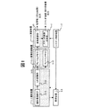
図1は本発明の実施例の簡易ステレオ画像入力装置を示す。簡易ステレオ画像入力装置は撮影対象を照明する照明装置1−2を備えたあるいは接続した撮影装置1−1に接続され、撮影対象の画像データと取り込み保持する画像記録装置1−3、照明の強弱が異なる撮影対象の複数の画像を比較することにより被写体の大まかな距離情報を求め、その結果から撮影対象のステレオ画像生成を行う演算装置1−4、上記各手段を制御するシステム制御装置1−5より構成される。
【0014】
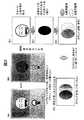
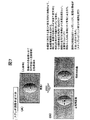
次に、本発明の実施例の画像入力方法の概要を図2を用いて説明する。(A)フラッシュありで撮影する。顔画像(前景)は明るく撮影されるが、カメラからの距離が遠い背景領域はフラッシュの明かりが届かないので暗く撮影される。(B)同じ画像をフラッシュなしで撮影する。顔画像(前景)も背景領域も暗く撮影される。(C)フラッシュありの画像とフラッシュなしの画像の濃淡値の引き算を行う。引き算の結果、明るさの差のある部分の映像が得られる。明るさの差が大きい部分が照明に近く、明るさの差の小さい部分が照明より遠いことから、前景と背景の大まかな距離情報を取得できる。(D)被写体の色・明るさの影響を吸収する為に2値化を行い2値化距離情報を得る。図の黒は前景であり、白は背景である。(E)前記2値化距離情報を用いて、撮影した映像の顔画像(前景)を取得し、これに視差を割り当て、右眼用画像と左眼用画像を作成する。しかし、このままでは、顔画像が平ら(書き割り)に見えるので、(F)右目用および左目用の顔画像に丸みを持たせ、自然に見えるように加工する。これにより、自然に見えるステレオ画像が得られる。
【0015】
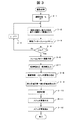
以下、簡易ステレオ画像入力装置の動作を図3に示す簡易ステレオ画像入力方法のフローチャートを用いて説明する。ある撮影対象に対して簡便にステレオ画像を生成する場合、まず照明条件と撮影枚数kを入力する(ステップ3−1)。照明条件および撮影枚数は予め決めておいても良い。次に照明装置1−2を用いて撮影対象をj番目の照明条件で照明し、撮影装置1−1により撮影した画像を入力する(ステップ3−2)。照明条件は照明の強弱で決定され、撮影装置1−1からの照明信号(例えば撮影のシャッターに同期したパルス光)にあわせて照明を行う。j番目に入力された画像信号は画像記録装置1−3のフレームメモリjに画像データとして格納される(ステップ3−3)。ステップ3−2からステップ3−3までの処理を撮影枚数kに達するまで繰り返す(ステップ3−4、3−5)。本実施例では撮影回数を2回(k=2)と想定しているので、画像記録手段1−3上のフレームメモリ(1−31、1−32)は2つであるが、撮影回数に応じてフレームメモリを増やしてもよい。画像の入力が終了すると、システム制御装置1−5の指令により撮影された画像データはフレームメモリから演算装置1−4の画像演算部1−41に転送される(ステップ3−6)。
【0016】
1−41の画像演算部では、複数画像を用いて適切な明るさの色情報(2次元画像)の出力を行う(3−7)。また、画像演算部1−41は照明条件の異なる複数の画像を比較し、複数画像間の明るさの差から大まかな距離情報を生成し、1−42のステレオ画像生成部に出力する(3−8)。距離情報の計算には、画像の差分計算・除算・2値化・エッジ検出などを用いることができる。また、色情報の合成処理としては、各画像のコントラストが最大になるように変換し最もコントラストが高いものを抽出する方法や、それらを適当な重み付けで合成する方法などがある。これらの処理の組合せをシステム制御装置1−5の命令により選択させても良い。
【0017】
図4は距離情報算出手順を示すフローチャートの例である。ここでは奥行き値として前後2値の奥行きとする。照明条件として「照明有り」「照明無し」の2つを設定し、撮影枚数は2枚とする。このとき「照明有り」のときの画像データのi番目の画素の画素値をAi、「照明無し」のときの画像データのi番目の画素の画素値をBi、2値化後のデータをDiで表す。奥行き値を計算するとき、まず閾値n・画像サイズsを決定する(ステップ4−1)。閾値nは画像を2値に分けるときのパラメータで任意に決定が可能である。また画像サイズsは入力する画像データの横方向画素サイズxと縦方向画素サイズyを掛け合わせた値とする。次に画素値AiとBiの差分を取り、閾値n以上であればDiを1、そうでなければ0とする(ステップ4−2〜4−4)。ステップ4−2〜4−4の処理を画像データの全画素分繰り返す(ステップ4−5〜4−6)。2値化後のデータDiの値が1の画素は撮影装置の近くにあると判断し手前に、その他の画素は遠くにあると判断する。またステップ4−2において、(Ai−Bi)/Biが、予め決められた割合より大きければDiを1、そうでなければ0としてもよい。また比較を行う複数の画像のデータがずれてしまう場合も、画素iの比較を行うときに近傍数画素の平均値をとることによって、ずれによる影響を軽減することが出来る他、動画対応も可能となる。
【0018】
図3のステップ3−9では、画像演算部1−41により得られた大まかな距離情報を用いて、ステレオ画像生成部1−42により、実際にステレオ画像として出力するための奥行き値を計算する。ここでは、まず、最終的に出力(表示)されるステレオ画像中の被写体の飛び出し量Lを指定し、この距離に観察されるように画像中の各画素の奥行きを決定する。具体的には、まず、距離情報を前景と背景の2種類に分割(2値化)した場合、前景の最大飛び出し量Lとする。しかし、このままでは前景が書き割りのように厚みのない物体として観察される。これを防止するため、図5に示すように、(A)に示された書き割り状態の右眼用画像と左眼用画像の各々について、(B)前景とされる物体の重心を計算し、(C)重心と前景内の各画素の距離を計算し、(D)前景領域のうちこの重心から離れた距離にある画素ほど遠景に設定するような処理を行う。この距離の決定方法は、遠景までの間を2次曲線で補間する方法、直線で補間する方法、重心を中心とした例えば30%の長さまでを最大飛び出し量Lとしそこから前景の境界までを2次曲面で補間する方法など、また、物体の厚みを任意に指定できるようにするなどが設定可能である。(E)は表示画像である。
【0019】
また遠景については、図6に示すように、前景の物体より遠方に観察されるように、奥行き値を決定する。具体的には、(A)に示す背景画像(左右眼)を、背景画像を画面の奥側に配置するのであれば、(B)に示すように、左眼用の画像ではより左方向に移動させ、右眼用の画像ではより右に移動させれば画面奥側に表示が可能である。前景と背景の奥行き決定に関する処理は、以下に示す3−10の処理と同一の処理に含めて行うことも可能である。
【0020】
図3のステップ3−9で設定した奥行き値を、ステップ3−10では画像上の視差情報に変換する。具体的には、ステップ3−9で指定した奥行きにステレオ画像を観察させるためには、両眼の間隔と画像中の1画素の大きさから三角測量の原理で計算される奥行き値と一致するように、ステレオ画像の視差を決定する。
【0021】
ステップ3−10で決定した視差に基づき、ステップ3−11では実際にステレオ画像を生成する。具体的には、図7に示すように、まず、(A)ステレオ画像(左右眼用画像)の元画像として、1−41で出力される2次元画像か、または1−31および1−32で出力される画像を用意する。次に、(B)指定した視差量に応じて画面上で各画素に対応する視差量を左右眼用画像内で左右方向に移動させる。例えば、画像中のある1点が画面手前方向に視差dの奥行き情報を持っている場合、その画素値を右眼用にはd/2だけ画像の左方向に移動させて画像を生成し、左眼用にはd/2だけ画像の右方向に移動させて画像を生成する。この際、視差が0のものについては、左右眼用画像にそのままコピーする。この方法で、左右画像間の対応点が存在するデータについてはステレオ画像の生成が可能であるが、ここで生成される左右眼用画像には、画素値(色データ)が存在しない場合が発生する。これを次のステップ3−12で処理する。
【0022】
色データの存在しない画素については、図8(A)に示すように、その画素の左右方向で色データが欠落していない画素の視差が左右で比較してより遠方に対応するデータを、欠落した画素の色データとする方法で実現できる(例1)。この他、色データの存在しない領域を隣接するより遠方の視差を持つ領域の色データで置き換える方法なども可能である(例2)。これにより、前景が背景を遮蔽する際に、前景と背景の左右方向の境界付近に発生する片眼のみに見える領域についても、背景領域の色データを用いて補間することで前景の遠方に存在しているという情報を与えられるため、ある程度自然なステレオ画像の生成が可能となる(図8(B))。
【0023】
以上により、ステレオ画像の生成が可能である。
【0024】
上記、ステレオ画像生成を行うためには、複数台のカメラを使用する必要がなく、また照明装置をカメラに隣接した位置に配置可能なため、従来の装置より小型化が可能であり、携帯端末等への搭載も可能となる。
【0025】
本発明の装置はコンピュータプログラムによっても実現でき、プログラムを記録媒体に記録することも、ネットワークを通して提供することも可能である。
【0026】
以上、本発明者によってなされた発明を、前記実施例に基づき具体的に説明したが、本発明は、前記実施例に限定されるものではなく、その要旨を逸脱しない範囲において種々変更可能であることは勿論である。
【0027】
【発明の効果】
以上述べたように本発明によれば以下に示すような効果が生じる。
本発明の請求項1の発明によれば、撮影装置が1台のみと複数用いる必要がないため、従来のステレオ画像撮影装置に比べ、小型化が可能となる。
請求項2の発明によれば、単純な2値化処理の結果を大まかな2つの距離と設定することで、照明光のムラや撮影対象の反射特性に影響を受けにくい、また計算負荷が少ない高速な処理が可能となる。
請求項3の発明によれば、複雑な計算処理をすることなく簡便に自然な奥行き知覚が得られるステレオ画像を生成することができる。
【図面の簡単な説明】
【図1】本発明の実施例の簡易ステレオ画像入力装置を示す図である。
【図2】本発明の実施例の画像入力方法の概要を示す図である。
【図3】簡易ステレオ画像入力方法のフローチャートの例を示す図である。
【図4】大まかな距離情報算出手順を示すフローチャートの例を示す図である。
【図5】書き割り回避処理を示す図である。
【図6】背景部の奥行き値決定方法を示す図である。
【図7】ステレオ画像生成方法を示す図である。
【図8】ステレオ画像生成により生じる色データの欠落の補間方法を示す図である。
【符号の説明】
1−1…撮像装置、1−2…照明装置、1−3…画像記録装置、1−4…演算装置、1−5…システム制御装置、1−11…個体撮像素子、1−12…A/D変換部、1−31…フレームメモリ1、1−32…フレームメモリ2、1−41…画像演算部、1−42…ステレオ画像生成部、3−1〜3−12…簡易ステレオ画像入力手順の各ステップ、4−1〜4−5…大まかな距離情報算出手順の各ステップ。[0001]
TECHNICAL FIELD OF THE INVENTION
The present invention relates to a simple stereo image input device, a method, a program, and a recording medium that generate a stereo image from a plurality of images captured by changing the presence or absence of illumination or the intensity of a captured object.
[0002]
[Prior art]
2. Description of the Related Art Conventionally, as a natural image input device for a stereo image display device, two or more cameras are arranged in parallel or with a slight convergence so that their optical axes intersect with each other, and the photographed images are left and right as they are. A method of inputting a display image to a display device has been used (see Non-Patent Document 1). Although this is the simplest configuration, it is more expensive because it requires the use of multiple cameras. Further, arranging a plurality of cameras in a limited size such as for a mobile phone is disadvantageous in terms of miniaturization.
[0003]
A method of generating a stereo image from a two-dimensional “moving” image captured by one camera has also been proposed (see Patent Document 1). In this method, one of the left and right eye images is input as a two-dimensional input moving image as it is, and the other eye image is delayed as a frame delay according to the magnitude of the motion vector of the input two-dimensional moving image. This is a method of stereoscopically viewing by changing the amount and inputting. In this method, since a stereo image is generated using motion information of a two-dimensional moving image, when a plurality of objects move in different directions, the parallax between the objects is reversed, and the stereoscopic image is disturbed. There is.
[0004]
On the other hand, a method of generating a stereo image from a two-dimensional “still” image has been proposed (see Patent Document 2). In this method, since a stereo image is generated from one still image, there is a shortcoming that information on distance is insufficient and the image quality level of the generated stereo image is low.
[0005]
[Patent Document 1]
Patent No. 2594235 (Method for converting 2D video to 3D video and 3D video generation device)
[Patent Document 2]
Patent No. 3067097 (3D image data generation method)
[Non-patent document 1]
Supervised by Takehiro Izumi, edited by NHK Science and Technical Research Laboratories, "Basics of 3D Video", Ohmsha, June 5, 1995, pp. 71-73
[0006]
[Problems to be solved by the invention]
Currently, mobile phones with a camera, notebook PCs, PDAs, and the like are being actively developed. Normally, images taken by a camera attached to these are only two-dimensional information. However, if the acquisition and generation of distance information becomes possible, the range of applications such as stereo image display is expanded. However, up to now, it has been necessary to use two cameras in order to input a stereo image, and the size and the price have been barriers to popularization.
[0007]
[Means for Solving the Problems]
SUMMARY OF THE INVENTION The present invention has been made to solve the above-mentioned problem, and makes it possible to generate a stereo image easily with a small size.
[0008]
The stereo image input device of the present invention includes: an image recording unit that records a plurality of images; and a depth value calculation unit that calculates a depth value of a shooting target based on a comparison operation of pixel values of corresponding pixels in the plurality of images. And a stereo image generating means for generating a stereo image based on the depth value obtained by the depth value calculating means.
[0009]
The stereo image input device according to the present invention operates as follows. A plurality of images are input to a shooting target under different lighting conditions. The depth value is calculated by comparing the plurality of images. As a comparison method, for example, "illuminated" and "non-illuminated" are set as illumination conditions, and when the difference between images under each condition is calculated, the greater the luminance difference, the closer to illumination.
[0010]
The depth value calculated at this time is coarse due to the unevenness of the illumination light and the reflection characteristics of the object to be photographed. However, the depth value is divided into a plurality of depth levels, and a parallax corresponding to the depth value is assigned to each level. In order to prevent the stereoscopic image from being perceived as described above, the parallax between the levels is changed so that the shooting target in the divided state is recognized as one object.
[0011]
Furthermore, information about occlusion of an object is more faithfully obtained by performing interpolation processing on data loss in a stereo image caused by the addition of parallax using image information at an adjacent and farther depth level. And a more natural stereo image can be generated.
[0012]
In this method, only one photographing device is required, so that the size can be reduced as compared with a case where a plurality of photographing devices are used. In addition, even in the case of detection with coarse accuracy, the parallax is changed by image processing using the approximate distance information of the object, and data loss processing is performed by generating a stereo image, thereby avoiding the perception of writing and observing. It is possible to present a high quality stereoscopic image to the user.
[0013]
BEST MODE FOR CARRYING OUT THE INVENTION
FIG. 1 shows a simplified stereo image input device according to an embodiment of the present invention. The simple stereo image input device is connected to a photographing device 1-1 having or connected to a lighting device 1-2 for illuminating a photographing target, and an image recording device 1-3 for capturing and holding image data of a photographing target, and the intensity of illumination. Calculates approximate distance information of the subject by comparing a plurality of images of the photographing targets having different image data, and generates a stereo image of the photographing target from the result, and a
[0014]
Next, an outline of an image input method according to an embodiment of the present invention will be described with reference to FIG. (A) Shoot with flash. The face image (foreground) is photographed brightly, but the background region that is far from the camera is photographed dark because the light of the flash does not reach. (B) Shoot the same image without flash. Both the face image (foreground) and the background area are shot dark. (C) Subtract the gray value of the image with flash and the image without flash. As a result of the subtraction, an image of a portion having a difference in brightness is obtained. Since a portion having a large difference in brightness is close to the illumination and a portion having a small difference in brightness is far from the illumination, rough distance information between the foreground and the background can be obtained. (D) Binarization is performed to absorb the effects of the color and brightness of the subject, and binarized distance information is obtained. In the figure, black is the foreground and white is the background. (E) Using the binarized distance information, obtain a face image (foreground) of the captured video, assign parallax thereto, and create a right-eye image and a left-eye image. However, in this state, the face image looks flat (split), so that (F) the face images for the right eye and the left eye are rounded and processed to look natural. As a result, a stereo image that looks natural can be obtained.
[0015]
Hereinafter, the operation of the simple stereo image input device will be described with reference to the flowchart of the simple stereo image input method shown in FIG. When a stereo image is easily generated for a certain photographing target, first, an illumination condition and the number k of photographed images are input (step 3-1). The lighting conditions and the number of shots may be determined in advance. Next, the object to be photographed is illuminated using the illumination device 1-2 under the j-th illumination condition, and an image captured by the imaging device 1-1 is input (step 3-2). The illumination condition is determined by the intensity of the illumination, and illumination is performed in accordance with an illumination signal from the imaging device 1-1 (for example, pulsed light synchronized with an imaging shutter). The j-th input image signal is stored as image data in the frame memory j of the image recording device 1-3 (step 3-3). The processing from step 3-2 to step 3-3 is repeated until the number of images reaches k (steps 3-4 and 3-5). In this embodiment, since the number of times of image capturing is assumed to be two (k = 2), the number of frame memories (1-31, 1-32) on the image recording means 1-3 is two. The frame memory may be increased accordingly. When the input of the image is completed, the image data photographed by the command of the system control device 1-5 is transferred from the frame memory to the image operation portion 1-41 of the operation device 1-4 (step 3-6).
[0016]
The image calculation unit 1-41 outputs color information (two-dimensional image) of appropriate brightness using a plurality of images (3-7). Further, the image calculation unit 1-41 compares a plurality of images having different lighting conditions, generates rough distance information from a difference in brightness between the plurality of images, and outputs the information to the stereo image generation unit 1-42 (3). -8). For the calculation of the distance information, image difference calculation, division, binarization, edge detection, and the like can be used. Examples of the color information synthesizing process include a method of converting each image so as to maximize the contrast and extracting an image having the highest contrast, and a method of synthesizing them with appropriate weighting. A combination of these processes may be selected by an instruction from the system controller 1-5.
[0017]
FIG. 4 is an example of a flowchart showing the procedure for calculating distance information. Here, the depth value is two depths before and after. Two lighting conditions, “lighting on” and “lighting off,” are set, and the number of shots is two. At this time, the pixel value of the i-th pixel of the image data when "illuminated" is Ai, the pixel value of the i-th pixel of the image data when "no illumination" is Bi, and the binarized data is Di. Expressed by When calculating the depth value, first, a threshold value n and an image size s are determined (step 4-1). The threshold value n can be arbitrarily determined by a parameter for dividing an image into binary values. The image size s is a value obtained by multiplying the horizontal pixel size x and the vertical pixel size y of the input image data. Next, the difference between the pixel values Ai and Bi is calculated, and if it is equal to or larger than the threshold value n, Di is set to 1, otherwise 0 is set (steps 4-2 to 4-4). The processing of steps 4-2 to 4-4 is repeated for all pixels of the image data (steps 4-5 to 4-6). The pixel whose value of the data Di after binarization is 1 is determined to be close to the image capturing apparatus, and the other pixels are determined to be near and far from the image capturing apparatus. In step 4-2, Di may be set to 1 if (Ai-Bi) / Bi is larger than a predetermined ratio, and may be set to 0 otherwise. Also, even when data of a plurality of images to be compared are shifted, by taking an average value of several neighboring pixels when comparing the pixel i, it is possible to reduce the influence of the shift and to cope with a moving image. It becomes.
[0018]
In step 3-9 in FIG. 3, the stereo image generation unit 1-42 calculates a depth value for actually outputting as a stereo image using the rough distance information obtained by the image calculation unit 1-41. . Here, first, the amount of projection L of the subject in the stereo image finally output (displayed) is specified, and the depth of each pixel in the image is determined so as to be observed at this distance. Specifically, first, when the distance information is divided into two types (binarization) of the foreground and the background, the maximum projection amount L of the foreground is set. However, in this state, the foreground is observed as an object having a small thickness such as writing. To prevent this, as shown in FIG. 5, for each of the right-eye image and left-eye image in the split state shown in FIG. , (C) calculates the distance between the center of gravity and each pixel in the foreground, and (D) performs a process of setting the pixels in the foreground area that are farther away from the center of gravity into the far view. This distance is determined by a method of interpolating a distance to a distant view with a quadratic curve, a method of interpolating with a straight line, a maximum projection amount L up to, for example, a length of 30% centered on the center of gravity, and a distance from that to the boundary of the foreground. It is possible to set a method of performing interpolation using a quadratic surface, a method of arbitrarily specifying the thickness of an object, and the like. (E) is a display image.
[0019]
For a distant view, as shown in FIG. 6, the depth value is determined so that the distant view is observed farther than the foreground object. Specifically, if the background image (left and right eyes) shown in (A) is arranged on the back side of the screen, as shown in (B), the image for the left eye is moved further leftward as shown in (B). By moving it and moving it further to the right in the image for the right eye, it is possible to display it on the far side of the screen. The processing related to the depth determination of the foreground and the background can be included in the same processing as the processing of 3-10 described below.
[0020]
The depth value set in step 3-9 in FIG. 3 is converted into parallax information on the image in step 3-10. Specifically, in order to observe the stereo image at the depth specified in step 3-9, the depth value calculated from the distance between the eyes and the size of one pixel in the image by the principle of triangulation is the same. Thus, the parallax of the stereo image is determined.
[0021]
At step 3-11, a stereo image is actually generated based on the parallax determined at step 3-10. Specifically, as shown in FIG. 7, first, (A) a two-dimensional image output at 1-41 as an original image of a stereo image (image for the left and right eyes) or 1-31 and 1-32 Prepare an image to be output with. Next, (B) the parallax amount corresponding to each pixel on the screen is moved in the left-right direction in the left-right image according to the specified parallax amount. For example, when one point in the image has depth information of the parallax d in the front direction of the screen, the pixel value is moved to the left direction of the image by d / 2 for the right eye, and an image is generated. For the left eye, an image is generated by moving the image to the right by d / 2. At this time, those having a parallax of 0 are copied as they are to the left and right eye images. With this method, a stereo image can be generated for data in which there is a corresponding point between the left and right images. However, there are cases where pixel values (color data) do not exist in the left and right eye images generated here. I do. This is processed in the next step 3-12.
[0022]
For a pixel having no color data, as shown in FIG. 8 (A), data corresponding to a farther distant pixel whose parallax is not lost in the left-right direction of the pixel is compared with the left-right direction. (Example 1). In addition, a method in which an area where no color data exists is replaced with color data of an adjacent area having a parallax that is farther away (Example 2). As a result, when the foreground blocks the background, even the region that appears near the boundary between the foreground and the background in the left-right direction and is visible only to one eye is located far away from the foreground by interpolating using the color data of the background region. Since it is given the information that the stereo image is being reproduced, a somewhat natural stereo image can be generated (FIG. 8B).
[0023]
As described above, a stereo image can be generated.
[0024]
In order to generate the above-mentioned stereo image, it is not necessary to use a plurality of cameras, and since the lighting device can be arranged at a position adjacent to the camera, it is possible to reduce the size of the conventional device, and It is also possible to mount it on such as
[0025]
The device of the present invention can also be realized by a computer program, and the program can be recorded on a recording medium or provided through a network.
[0026]
As described above, the invention made by the inventor has been specifically described based on the embodiment. However, the present invention is not limited to the embodiment, and can be variously modified without departing from the gist of the invention. Of course.
[0027]
【The invention's effect】
As described above, according to the present invention, the following effects are produced.
According to the first aspect of the present invention, since there is no need to use only one photographing device and a plurality of photographing devices, it is possible to reduce the size as compared with the conventional stereo image photographing device.
According to the second aspect of the present invention, by setting the result of the simple binarization process to roughly two distances, it is hard to be affected by unevenness of illumination light and the reflection characteristic of the photographing target, and the calculation load is small. High-speed processing becomes possible.
According to the invention of
[Brief description of the drawings]
FIG. 1 is a diagram showing a simple stereo image input device according to an embodiment of the present invention.
FIG. 2 is a diagram illustrating an outline of an image input method according to an embodiment of the present invention.
FIG. 3 is a diagram illustrating an example of a flowchart of a simple stereo image input method.
FIG. 4 is a diagram illustrating an example of a flowchart illustrating a rough distance information calculation procedure.
FIG. 5 is a diagram illustrating a write split avoidance process;
FIG. 6 is a diagram illustrating a method of determining a depth value of a background portion.
FIG. 7 is a diagram illustrating a stereo image generation method.
FIG. 8 is a diagram illustrating a method of interpolating missing color data caused by stereo image generation.
[Explanation of symbols]
1-1: imaging device, 1-2: lighting device, 1-3: image recording device, 1-4: arithmetic device, 1-5: system control device, 1-11: solid-state image sensor, 1-12: A / D conversion unit, 1-31 ...
Claims (5)
前記複数の画像を記録する画像記録手段と、
前記複数の画像における対応する画素の画素値の比較演算に基づいて撮影対象の奥行き値を算出する奥行き値算出手段と、
前記奥行き値算出手段により得られた奥行き値を元にステレオ画像を生成するステレオ画像生成手段と
を備えることを特徴とする簡易ステレオ画像入力装置。An apparatus for generating a stereo image from a plurality of images taken with or without illumination or intensity of the shooting target,
Image recording means for recording the plurality of images,
Depth value calculation means for calculating a depth value of a shooting target based on a comparison operation of pixel values of corresponding pixels in the plurality of images,
A simple stereo image input device comprising: a stereo image generating means for generating a stereo image based on the depth value obtained by the depth value calculating means.
前記複数の画像を記録する画像記録過程と、
前記複数の画像における対応する画素の画素値の比較演算に基づいて撮影対象の奥行き値を算出する奥行き値算出過程と、
前記奥行き値算出手段により得られた奥行き値を元にステレオ画像を生成するステレオ画像生成過程と
を備えることを特徴とする簡易ステレオ画像入力方法。A method of generating a stereo image from a plurality of images taken by changing the presence or absence or intensity of illumination for the shooting target,
An image recording step of recording the plurality of images,
A depth value calculating step of calculating a depth value of a shooting target based on a comparison operation of pixel values of corresponding pixels in the plurality of images,
A stereo image generating step of generating a stereo image based on the depth value obtained by the depth value calculating means.
照明装置の条件を変更した複数画像を撮影し、その画像演算により、撮影対象の距離情報を複数のレベルに切り分ける過程と、
前記複数のレベルの距離情報を実際に表示したい距離情報に変換する過程と、
前記距離情報をステレオ画像の視差情報に変換する過程と、
前記視差情報に基づき、ステレオ画像を生成する過程と、
前記ステレオ画像生成により発生する、データの欠落を周辺の画像データを用いて補間する過程と
を有することを特徴とする簡易ステレオ画像入力方法。A simple stereo image input method according to claim 2,
A process of photographing a plurality of images in which the conditions of the lighting device have been changed, and dividing the distance information of the photographing target into a plurality of levels by image calculation;
A step of converting the plurality of levels of distance information into distance information actually desired to be displayed,
Converting the distance information into parallax information of a stereo image,
Generating a stereo image based on the parallax information;
Interpolating missing data generated by the generation of the stereo image using surrounding image data.
Priority Applications (1)
| Application Number | Priority Date | Filing Date | Title |
|---|---|---|---|
| JP2002366342A JP3990271B2 (en) | 2002-12-18 | 2002-12-18 | Simple stereo image input device, method, program, and recording medium |
Applications Claiming Priority (1)
| Application Number | Priority Date | Filing Date | Title |
|---|---|---|---|
| JP2002366342A JP3990271B2 (en) | 2002-12-18 | 2002-12-18 | Simple stereo image input device, method, program, and recording medium |
Publications (2)
| Publication Number | Publication Date |
|---|---|
| JP2004200973A true JP2004200973A (en) | 2004-07-15 |
| JP3990271B2 JP3990271B2 (en) | 2007-10-10 |
Family
ID=32763577
Family Applications (1)
| Application Number | Title | Priority Date | Filing Date |
|---|---|---|---|
| JP2002366342A Expired - Fee Related JP3990271B2 (en) | 2002-12-18 | 2002-12-18 | Simple stereo image input device, method, program, and recording medium |
Country Status (1)
| Country | Link |
|---|---|
| JP (1) | JP3990271B2 (en) |
Cited By (17)
| Publication number | Priority date | Publication date | Assignee | Title |
|---|---|---|---|---|
| JP2010158009A (en) * | 2008-12-26 | 2010-07-15 | Samsung Electronics Co Ltd | Video processing method and device therefor |
| WO2010140332A1 (en) * | 2009-06-01 | 2010-12-09 | パナソニック株式会社 | Stereoscopic image display apparatus |
| JP2012029168A (en) * | 2010-07-26 | 2012-02-09 | Toshiba Corp | Parallax image generation method and device |
| WO2012133117A1 (en) * | 2011-03-25 | 2012-10-04 | 京セラ株式会社 | Electronic apparatus |
| JP2012212984A (en) * | 2011-03-30 | 2012-11-01 | Nec Personal Computers Ltd | Image processing device and image processing method |
| WO2013014710A1 (en) * | 2011-07-27 | 2013-01-31 | パナソニック株式会社 | Stereoscopic image adjustment device |
| JP2013074585A (en) * | 2011-09-29 | 2013-04-22 | Jvc Kenwood Corp | Stereoscopic image generation device and stereoscopic image generation method |
| WO2013080544A1 (en) * | 2011-11-30 | 2013-06-06 | パナソニック株式会社 | Stereoscopic image processing apparatus, stereoscopic image processing method, and stereoscopic image processing program |
| JPWO2011135857A1 (en) * | 2010-04-28 | 2013-07-18 | パナソニック株式会社 | Image converter |
| KR101314101B1 (en) | 2012-09-24 | 2013-10-04 | 위프코 주식회사 | System for three-dimensional measurement and method therefor |
| JP2014512144A (en) * | 2011-04-15 | 2014-05-19 | クゥアルコム・インコーポレイテッド | Devices and methods for warping and hole filling during view synthesis |
| JP5502211B2 (en) * | 2011-01-17 | 2014-05-28 | パナソニック株式会社 | Stereoscopic image processing apparatus and stereoscopic image processing method |
| KR20150005546A (en) * | 2012-04-19 | 2015-01-14 | 톰슨 라이센싱 | Method and device for correcting distortion errors due to accommodation effect in stereoscopic display |
| US9124874B2 (en) | 2009-06-05 | 2015-09-01 | Qualcomm Incorporated | Encoding of three-dimensional conversion information with two-dimensional video sequence |
| US9210396B2 (en) | 2011-03-31 | 2015-12-08 | JVC Kenwood Corporation | Stereoscopic image generation apparatus and stereoscopic image generation method |
| WO2017126711A1 (en) * | 2016-01-19 | 2017-07-27 | 전자부품연구원 | Illumination control method and system for optimal depth recognition of stereoscopic camera |
| US10313650B2 (en) | 2016-06-23 | 2019-06-04 | Electronics And Telecommunications Research Institute | Apparatus and method for calculating cost volume in stereo matching system including illuminator |
-
2002
- 2002-12-18 JP JP2002366342A patent/JP3990271B2/en not_active Expired - Fee Related
Cited By (29)
| Publication number | Priority date | Publication date | Assignee | Title |
|---|---|---|---|---|
| JP2010158009A (en) * | 2008-12-26 | 2010-07-15 | Samsung Electronics Co Ltd | Video processing method and device therefor |
| US8767048B2 (en) | 2008-12-26 | 2014-07-01 | Samsung Electronics Co., Ltd. | Image processing method and apparatus therefor |
| JP5308523B2 (en) * | 2009-06-01 | 2013-10-09 | パナソニック株式会社 | Stereoscopic image display device |
| WO2010140332A1 (en) * | 2009-06-01 | 2010-12-09 | パナソニック株式会社 | Stereoscopic image display apparatus |
| CN102124749A (en) * | 2009-06-01 | 2011-07-13 | 松下电器产业株式会社 | Stereoscopic image display apparatus |
| US8704881B2 (en) | 2009-06-01 | 2014-04-22 | Panasonic Corporation | Stereoscopic image display apparatus |
| US9124874B2 (en) | 2009-06-05 | 2015-09-01 | Qualcomm Incorporated | Encoding of three-dimensional conversion information with two-dimensional video sequence |
| JPWO2011135857A1 (en) * | 2010-04-28 | 2013-07-18 | パナソニック株式会社 | Image converter |
| JP2012029168A (en) * | 2010-07-26 | 2012-02-09 | Toshiba Corp | Parallax image generation method and device |
| JP5502211B2 (en) * | 2011-01-17 | 2014-05-28 | パナソニック株式会社 | Stereoscopic image processing apparatus and stereoscopic image processing method |
| US8750601B2 (en) | 2011-01-17 | 2014-06-10 | Panasonic Corporation | Three-dimensional image processing device, and three-dimensional image processing method |
| US9462259B2 (en) | 2011-03-25 | 2016-10-04 | Kyocera Corporation | Electronic device |
| WO2012133117A1 (en) * | 2011-03-25 | 2012-10-04 | 京セラ株式会社 | Electronic apparatus |
| JP2012205148A (en) * | 2011-03-25 | 2012-10-22 | Kyocera Corp | Electronic apparatus |
| JP2012212984A (en) * | 2011-03-30 | 2012-11-01 | Nec Personal Computers Ltd | Image processing device and image processing method |
| US9210396B2 (en) | 2011-03-31 | 2015-12-08 | JVC Kenwood Corporation | Stereoscopic image generation apparatus and stereoscopic image generation method |
| JP2014512144A (en) * | 2011-04-15 | 2014-05-19 | クゥアルコム・インコーポレイテッド | Devices and methods for warping and hole filling during view synthesis |
| WO2013014710A1 (en) * | 2011-07-27 | 2013-01-31 | パナソニック株式会社 | Stereoscopic image adjustment device |
| JP2013074585A (en) * | 2011-09-29 | 2013-04-22 | Jvc Kenwood Corp | Stereoscopic image generation device and stereoscopic image generation method |
| US9602797B2 (en) | 2011-11-30 | 2017-03-21 | Panasonic Intellectual Property Management Co., Ltd. | Stereoscopic image processing apparatus, stereoscopic image processing method, and stereoscopic image processing program |
| JP5307953B1 (en) * | 2011-11-30 | 2013-10-02 | パナソニック株式会社 | Stereoscopic image processing apparatus, stereoscopic image processing method, and stereoscopic image processing program |
| WO2013080544A1 (en) * | 2011-11-30 | 2013-06-06 | パナソニック株式会社 | Stereoscopic image processing apparatus, stereoscopic image processing method, and stereoscopic image processing program |
| KR20150005546A (en) * | 2012-04-19 | 2015-01-14 | 톰슨 라이센싱 | Method and device for correcting distortion errors due to accommodation effect in stereoscopic display |
| JP2015520961A (en) * | 2012-04-19 | 2015-07-23 | トムソン ライセンシングThomson Licensing | Method and apparatus for correcting distortion error due to adjustment effect in stereoscopic display |
| US10110872B2 (en) | 2012-04-19 | 2018-10-23 | Interdigital Madison Patent Holdings | Method and device for correcting distortion errors due to accommodation effect in stereoscopic display |
| KR102066058B1 (en) | 2012-04-19 | 2020-01-14 | 인터디지탈 매디슨 페이튼트 홀딩스 | Method and device for correcting distortion errors due to accommodation effect in stereoscopic display |
| KR101314101B1 (en) | 2012-09-24 | 2013-10-04 | 위프코 주식회사 | System for three-dimensional measurement and method therefor |
| WO2017126711A1 (en) * | 2016-01-19 | 2017-07-27 | 전자부품연구원 | Illumination control method and system for optimal depth recognition of stereoscopic camera |
| US10313650B2 (en) | 2016-06-23 | 2019-06-04 | Electronics And Telecommunications Research Institute | Apparatus and method for calculating cost volume in stereo matching system including illuminator |
Also Published As
| Publication number | Publication date |
|---|---|
| JP3990271B2 (en) | 2007-10-10 |
Similar Documents
| Publication | Publication Date | Title |
|---|---|---|
| US11756223B2 (en) | Depth-aware photo editing | |
| JP6563453B2 (en) | Generation of a depth map for an input image using an exemplary approximate depth map associated with an exemplary similar image | |
| KR101452172B1 (en) | Method, apparatus and system for processing depth-related information | |
| JP3990271B2 (en) | Simple stereo image input device, method, program, and recording medium | |
| US20220215568A1 (en) | Depth Determination for Images Captured with a Moving Camera and Representing Moving Features | |
| US9807372B2 (en) | Focused image generation single depth information from multiple images from multiple sensors | |
| US20130250053A1 (en) | System and method for real time 2d to 3d conversion of video in a digital camera | |
| JP2011166264A (en) | Image processing apparatus, imaging device and image processing method, and program | |
| CA2669016A1 (en) | System and method for compositing 3d images | |
| JP2014056466A (en) | Image processing device and method | |
| CN102959942B (en) | Image capture device for stereoscopic viewing-use and control method thereof | |
| CN101821769A (en) | Image generation method, device, its program and program recorded medium | |
| US9661307B1 (en) | Depth map generation using motion cues for conversion of monoscopic visual content to stereoscopic 3D | |
| TW201301202A (en) | Image processing method and image processing apparatus thereof | |
| US20160180514A1 (en) | Image processing method and electronic device thereof | |
| JP2013025649A (en) | Image processing device, image processing method, and program | |
| US20140192163A1 (en) | Image pickup apparatus and integrated circuit therefor, image pickup method, image pickup program, and image pickup system | |
| KR20080047673A (en) | Apparatus for transforming 3d image and the method therefor | |
| JP6128748B2 (en) | Image processing apparatus and method | |
| JP2004229093A (en) | Method, device, and program for generating stereoscopic image, and recording medium | |
| US8908012B2 (en) | Electronic device and method for creating three-dimensional image | |
| JP2004133919A (en) | Device and method for generating pseudo three-dimensional image, and program and recording medium therefor | |
| KR101289283B1 (en) | A holographic display method using a hybrid image acquisition system | |
| CN107845108B (en) | Optical flow value calculation method and device and electronic equipment | |
| TWI504936B (en) | Image processing device |
Legal Events
| Date | Code | Title | Description |
|---|---|---|---|
| A621 | Written request for application examination |
Free format text: JAPANESE INTERMEDIATE CODE: A621 Effective date: 20050124 |
|
| A977 | Report on retrieval |
Free format text: JAPANESE INTERMEDIATE CODE: A971007 Effective date: 20070129 |
|
| A131 | Notification of reasons for refusal |
Free format text: JAPANESE INTERMEDIATE CODE: A131 Effective date: 20070213 |
|
| A521 | Written amendment |
Free format text: JAPANESE INTERMEDIATE CODE: A523 Effective date: 20070416 |
|
| TRDD | Decision of grant or rejection written | ||
| A01 | Written decision to grant a patent or to grant a registration (utility model) |
Free format text: JAPANESE INTERMEDIATE CODE: A01 Effective date: 20070717 |
|
| A61 | First payment of annual fees (during grant procedure) |
Free format text: JAPANESE INTERMEDIATE CODE: A61 Effective date: 20070719 |
|
| FPAY | Renewal fee payment (event date is renewal date of database) |
Free format text: PAYMENT UNTIL: 20100727 Year of fee payment: 3 |
|
| R150 | Certificate of patent or registration of utility model |
Free format text: JAPANESE INTERMEDIATE CODE: R150 |
|
| FPAY | Renewal fee payment (event date is renewal date of database) |
Free format text: PAYMENT UNTIL: 20100727 Year of fee payment: 3 |
|
| FPAY | Renewal fee payment (event date is renewal date of database) |
Free format text: PAYMENT UNTIL: 20110727 Year of fee payment: 4 |
|
| FPAY | Renewal fee payment (event date is renewal date of database) |
Free format text: PAYMENT UNTIL: 20120727 Year of fee payment: 5 |
|
| FPAY | Renewal fee payment (event date is renewal date of database) |
Free format text: PAYMENT UNTIL: 20130727 Year of fee payment: 6 |
|
| S531 | Written request for registration of change of domicile |
Free format text: JAPANESE INTERMEDIATE CODE: R313531 |
|
| R350 | Written notification of registration of transfer |
Free format text: JAPANESE INTERMEDIATE CODE: R350 |
|
| LAPS | Cancellation because of no payment of annual fees |