JP2004199301A - Image processor - Google Patents
Image processor Download PDFInfo
- Publication number
- JP2004199301A JP2004199301A JP2002366040A JP2002366040A JP2004199301A JP 2004199301 A JP2004199301 A JP 2004199301A JP 2002366040 A JP2002366040 A JP 2002366040A JP 2002366040 A JP2002366040 A JP 2002366040A JP 2004199301 A JP2004199301 A JP 2004199301A
- Authority
- JP
- Japan
- Prior art keywords
- image
- image processing
- dimensional
- face image
- processing apparatus
- Prior art date
- Legal status (The legal status is an assumption and is not a legal conclusion. Google has not performed a legal analysis and makes no representation as to the accuracy of the status listed.)
- Pending
Links
Images


Classifications
-
- G—PHYSICS
- G06—COMPUTING; CALCULATING OR COUNTING
- G06T—IMAGE DATA PROCESSING OR GENERATION, IN GENERAL
- G06T11/00—2D [Two Dimensional] image generation
- G06T11/60—Editing figures and text; Combining figures or text
-
- G—PHYSICS
- G06—COMPUTING; CALCULATING OR COUNTING
- G06T—IMAGE DATA PROCESSING OR GENERATION, IN GENERAL
- G06T15/00—3D [Three Dimensional] image rendering
- G06T15/10—Geometric effects
Abstract
Description
【0001】
【発明の属する技術分野】
本発明は、画像を変形させる画像加工装置に関するものであり、特に、顔写真等の顔画像を加工できる携帯電話機に用いるのに好適である。
【0002】
【従来の技術】
従来の携帯電話機における顔写真等の顔画像の加工方法としては、ネガ反転やセピア化などのように階調変換を行うものや、イラストやフレームを付加して合成するものなどがあった。これらの加工方法においては、元となる画像の形状は加工されなかった。
【0003】
またコンピュータ等において画像の形状を加工する方法としては、3次元グラフィックスを利用したテクスチャマッピングの技法が挙げられる。従来の顔写真等の顔画像の加工方法におけるテクスチャマッピングでは、2次元のテクスチャ画像に2次元空間の中だけで変形を加えたり、3次元空間内で3次元オブジェクトモデルを構築してそのモデルを形成する個々の面に対して2次元テクスチャ画像を貼り付けたりする方法が採られてきた。このような画像加工方法の例は、例えば特許文献1に記載されている。
【0004】
【特許文献1】
特開2000−172874号公報
【0005】
【発明が解決しようとする課題】
従来の携帯電話機における顔画像や顔写真の加工方法は、以上のように、基本的には2次元の座標空間の中でのみ行われていたので、ユーザの興味を持続させることが難しいという問題点があった。
【0006】
またユーザの興味を持続させるためには、複雑なモデルを準備しなければならず、その加工のために膨大な演算処理が必要になるという問題点があった。
【0007】
本発明は以上の問題点を解決するためになされたものであり、複雑なモデルの準備やその加工のための膨大な演算処理を要することなく、簡単な処理でユーザの興味を持続させるような視覚的効果が得られる、顔写真等の顔画像を扱うのに適した画像加工装置を提供することを目的とする。
【0008】
【課題を解決するための手段】
請求項1に記載の発明に係る画像加工装置は、2次元画像を入力させる画像入力手段と、入力された前記2次元画像を記憶する画像記憶手段と、記憶された前記2次元画像上に屈曲境界線を設定する屈曲境界線設定手段と、設定された前記屈曲境界線に沿って前記2次元画像を指定された屈曲角度で3次元空間内において屈曲させるとともに、視線の深さ方向に対する回転を規定する所定の回転軸を中心として指定された回転角度で回転させた画像を作成する画像加工手段と、前記画像加工手段により作成された前記画像を表示する画像表示手段とを備える。
【0009】
【発明の実施の形態】
<実施の形態1>
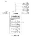
図1は、本発明の実施の形態1に係る画像加工装置100を示す構成図である。画像加工装置100は、中央処理装置(CPU)110と、指示入力装置120と、画像入力装置130と、通信装置140と、画像表示装置150と、記憶装置160とを備える。中央処理装置110は、画像加工装置100の全体の制御を行う。指示入力装置120は、中央処理装置100への指示をユーザが入力するキーボード等である。画像入力装置130は、カメラやスキャナ、ビデオ等から画像を入力させる装置である。また画像加工装置100は、画像データ等の送受信を行う通信装置140を介して、インターネット等から画像を入力させることもできる。画像表示装置150は、画像を表示するディスプレイ等である。記憶装置160は、データを格納するメモリ等である。中央処理装置110は、所定のプログラムに従って制御されることにより、屈曲境界線設定手段111と、ポリゴン加工手段112およびテクスチャ貼り付け手段113を有する画像加工手段116と、フォグ処理手段114と、光源処理手段115として動作する機能を有する。
【0010】
図2は、画像加工装置100を用いた画像加工の処理手順を示すフローチャートである。
【0011】
まずステップS1では、画像入力装置130から、例えば図3に示されるような顔画像500が入力される。入力された顔画像500は、記憶装置160に取り込まれる。このときに複数の顔画像を入力して記憶装置160に記憶しておくことにより、後述のステップS13において、原画像即ち加工前の顔画像500を入れ替える作業を容易にすることができる。
【0012】
ステップS2では、後述のステップS5〜S7において、顔画像500を縦方向(y軸方向)に屈曲させるための屈曲角θを、指示入力装置120からユーザが入力することにより設定する。
【0013】
ステップS3では、屈曲された顔画像500を後述のステップS8においてx軸を中心としてユーザの視線の深さ方向に回転させるための回転角αを、指示入力装置120からユーザが入力することにより設定する。
【0014】
ステップS4では、屈曲境界線設定手段111が、顔画像500上で縦方向の3本の屈曲境界線を設定する。図3に示すように、顔画像500の横方向をx軸、縦方向をy軸とする。顔画像500の左端のx座標を0.0、顔画像の右端のx座標を1.0、顔座標の下端のy座標を0.0、顔座標の上端のy座標を1.0とする。ユーザは画像表示装置150に表示された顔画像500を見ながら指示入力装置120に入力することにより、左右それぞれの目の位置のx座標である座標eLおよび座標eRを指定する。屈曲境界線設定手段111は、指定された座標eLおよび座標eRに基づいて当該座標eL,eRを設定するとともに、
【0015】
【数1】

により座標eMを設定する。
【0017】
顔画像500は、直線x=0.0、x=eL、x=eM、x=eR、x=1.0によって4つの四角形に分割される。図3に示すように、xy平面に垂直な方向にz軸を定め、顔画像500を、平面z=0上に置かれた平面として扱うと、分割された四角形は、4つのポリゴン10〜40として、それらの頂点の座標で表現して扱うことができる。このとき顔画像500は、ポリゴン10〜40上に、テクスチャ50〜80が貼り付けられた、2次元テクスチャ画像として扱われる。ポリゴン10〜40の頂点の座標は、ポリゴン10では点11(0.0,0.0,0.0)、点12(0.0,1.0,0.0)、点13(eL,0.0,0.0)、点14(eL,1.0,0.0)、ポリゴン20では点21(eL,0.0,0.0)、点22(eL,1.0,0.0)、点23(eM,0.0,0.0)、点24(eM,1.0,0.0)、ポリゴン30では点31(eM,0.0,0.0)、点32(eM,1.0,0.0)、点33(eR,0.0,0.0)、点34(eR,1.0,0.0)、ポリゴン40では点41(eR,0.0,0.0)、点42(eR,1.0,0.0)、点43(1.0,0.0,0.0)、点44(1.0,1.0,0.0)となる。
【0018】
テクスチャ50〜80の頂点の座標は、ポリゴン10〜40の頂点の座標からz座標成分を取り去ることにより導くことができる。従って、テクスチャ50〜80の頂点の座標は、テクスチャ50では点51(0.0,0.0)、点52(0.0,1.0)、点53(eL,0.0)、点54(eL,1.0)、テクスチャ60では点61(eL,0.0)、点62(eL,1.0)、点63(eM,0.0)、点64(eM,1.0)、テクスチャ70では点71(eM,0.0)、点72(eM,1.0)、点73(eR,0.0)、点74(eR,1.0)、テクスチャ80では点81(eR,0.0)、点82(eR,1.0)、点83(1.0,0.0)、点84(1.0,1.0)となる。
【0019】
以下に説明するステップS5〜S10において、画像加工手段116が、ポリゴン10〜40の頂点の座標を3次元空間内で平行移動および回転させた後に2次元平面上に投影し、その各ポリゴンにテクスチャ50〜80を貼り付ける(マッピングする)ことにより、顔画像500が加工される。
【0020】
まず、以下のステップS5〜S7により、ポリゴン加工手段112が顔画像500を縦方向(y軸方向)にθだけ屈曲させる。ステップS5〜S7では、顔画像500が、直線x=eLと直線x=eRとに沿って凸形になり、直線x=eMに沿って凹形になるように屈曲させる。
【0021】
ステップS5では、図4に示すように、ポリゴン加工手段112がy軸を回転軸としてポリゴン10〜40を回転させる。回転角は、ポリゴン10,30がθで、ポリゴン20,40が−θである。回転によるこの座標変換を表す行列は、ポリゴン10,30については式(2)、ポリゴン20,40については式(3)のように表すことができる。なお、後述のステップS9で説明する透視法射影による座標変換が4行4列の行列で表されるため、ポリゴン座標も3次元グラフィックスにおける同次座標として値1を付加して4次元座標とし、全ての座標変換を4行4列の行列で表すことにする。
【0022】
【数2】
【数3】
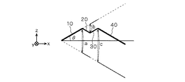
ステップS5でのθの回転により、辺を接していたポリゴン10〜40が分離されてしまう。そこで、ステップS6では、再びポリゴン10〜40の辺が接するように、ポリゴン加工手段112がポリゴン20〜40の平行移動を行う。このとき図5に示すように、ポリゴン10は平行移動させずに、ポリゴン10に対してポリゴン20,30,40をそれぞれz軸方向に平行移動させる。ポリゴン20,30,40の移動距離a,b,cは、それぞれ
【0025】
【数4】
【数5】
【数6】
により算出することができる。平行移動によるこの座標変換を表す行列は、ポリゴン20,30,40について、式(7)、式(8)、式(9)のように表すことができる。
【0029】
【数7】
【数8】
【数9】
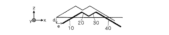
ステップS6では、ポリゴン10に対してポリゴン20,30,40を平行移動するので、顔画像500は、x座標が小さくz座標が大きい方へ寄ってしまい、後述のステップS9でxy平面上に投影したときに、画像表示装置150に表示される顔画像500が左にずれたり、大きくなってしまったりする。これを補正するために、ステップS7では図6に示すように、x座標が大きくz座標が小さい方へ、ポリゴン加工手段112がポリゴン10〜40を平行移動させる。x方向の移動距離をd、z方向の距離をeとすると、dとeとはそれぞれ式(10)、式(11)のように表すことができる。
【0033】
【数10】
【数11】
平行移動によるこの座標変換を表す行列は、ポリゴン10〜40について、式(12)のように表すことができる。
【0036】
【数12】
ステップS8では、ポリゴン加工手段112が、ポリゴン10〜40をx軸を中心としてユーザの視線の深さ方向に回転角αだけ回転させることにより、顔画像500の表情を変化させる。回転角αが負の場合に、回転させたポリゴン10〜40をx軸の正の方向から見た様子を図7に示す。また回転角αが正の場合に、回転させたポリゴン10〜40をx軸の正の方向から見た様子を図8に示す。回転によるこの座標変換を表す行列は、ポリゴン10〜40について、式(13)のように表すことができる。
【0038】
【数13】
ステップS9では、ポリゴン加工手段112が、ポリゴン10〜40をxy平面上に投影させる。3次元空間内に置かれた物体を2次元の画像表示装置150で表示させる場合には、3次元グラフィックスにおける射影方法である透視法射影を用いる。透視法射影を用いることにより、遠くにあるものは小さく、近くにあるものは大きく表示させて、実際に人間の目で見たときの画像に近づけることができる。これにより、投影された顔画像500の遠近感が表現されて、実際に顔画像500を手にとって折り曲げて斜め上方もしくは斜め下方から見ているかのように表示することができる。透視法射影によるこの座標変換を表す行列は、ポリゴン10〜40について、式(14)のように表すことができる。ここで、lは透視法射影における視体積の左端座標、rは右端座標、tは上端座標、bは下端座標、nは手前端座標、fは奥端座標である。
【0040】
【数14】
ステップS10では、テクスチャ貼り付け手段113が、ポリゴン10〜40に2次元テクスチャ画像であるテクスチャ50〜80を貼り付ける(テクスチャマッピング)。図7,8にそれぞれ示されるポリゴン10〜40にテクスチャ50〜80を貼り付けた顔画像500を図9,10に示す。ステップS5〜S8の座標変換により、ポリゴン10〜40の頂点の座標が変換されているため、テクスチャ50〜80を貼り付ける際には、テクスチャ50〜80を変換してから貼り付ける必要がある。このテクスチャ50〜80の変換は、座標変換前のポリゴン10〜40の頂点の座標と、座標変換後のポリゴン10〜40の頂点の座標とから、補間演算を行い、座標変換後のポリゴン10〜40に、変換されたテクスチャ50〜80を貼り付ける。
【0042】
以上の工程の説明においては座標変換を表す行列を1つずつ分けて説明したが、本実施の形態のように座標変換に伴う全てのパラメータが準備できる場合には、中央処理装置110が、それぞれの座標変換を表す行列から1つの行列積をあらかじめ算出しておいてもよい。これにより、顔画像加工前のポリゴン10〜40の頂点の座標から、1回の行列演算を行うことで、顔画像加工後のポリゴン10〜40の頂点の座標を算出することができる。
【0043】
なお、ステップS2(S3)においては、ユーザが直接に屈曲角θ(回転角α)の値を指示入力装置120から入力したが、所定のキーが押し下げられた時間に比例して屈曲角θ(回転角α)を増加させて、その屈曲角θ(回転角α)に対応する顔画像500をユーザが画像表示装置150上で確認しながら、任意の角度でキーの押し下げをとりやめることにより、屈曲角θ(回転角α)の値を設定してもよい。
【0044】
ステップS4においては、屈曲境界線設定手段111が式(1)を用いて座標eMを設定するが、式(1)を用いることなく、ユーザが任意に座標eMを指定してもよい。座標eLおよび座標eRについても、左右それぞれの目の位置ではなく、ユーザが顔画像の任意の位置に指定してもよい。また座標eLおよび座標eRについては、ユーザが指定するのではなく、目の形状と色(黒目の周囲に白目がある)の特徴を、例えば濃度分布を用いた画像処理等により判別することにより、屈曲境界線設定手段111が自動的に設定してもよい。この場合の顔画像の大きさや顔の向きは、屈曲境界線設定手段111が自動的に座標eLおよび座標eRすなわち顔画像上で目を認識できる程度に、制約される必要がある。
【0045】
ステップS6において、x軸を中心とした顔画像500の回転角αがユーザにより入力されるが、ユーザは回転角αを入力するだけではなく、顔画像500が回転角αを連続的に変化させる動作モードを選択することもできる。これにより、顔画像500の表情を変化させ続けることが可能となり、ユーザの興味をより長く持続させることができる。
【0046】
ステップS9に先だちユーザは、ステップS8−1において、遠近感をさらに強調するためのフォグ処理を行うためのフォグ処理手段114を用いて顔画像500にフォグ処理を行うことを、選択することができる。フォグ処理は、物体の色調を式(15)のように変えることにより、視点から遠い部分がかすんで見えるようにする技法である。
【0047】
【数15】
ここで、fはフォグ係数、Ciは物体(テクスチャ50〜80が貼り付けられたポリゴン10〜40)の色、Cfはフォグの色である。フォグ係数fは、視点と、回転角αだけ回転させたポリゴン10〜40との距離zに対して、(例えば式(16)に示すように、ユーザが設定可能な係数densityを比例定数として)指数関数的に減衰させてもよい。このフォグ処理を行うことによって、より現実味のある表示を行うことできる。
【0049】
【数16】
また、ステップS9に先だちユーザは、ステップS8−2において、物体に光が当たったかのように、物体の色を変化させたり、物体にハイライトを加えたりするための光源処理(OpenGL Programming Guide P.188−P.192参照)を行うことを、選択することができる。光源処理手段115は、視点の座標と、光源の座標と、回転角αだけ回転させたポリゴン10〜40の頂点の座標とに応じて、ポリゴン10〜40に対応するテクスチャ50〜80の色を変化させる。これにより、実際に顔画像500を手にとって、所定の方向から光を照射したかのように、顔画像500の全体に明暗をつけることができ、より現実味のある表示を行うことできる。
【0051】
以上のステップS4〜S10の工程で顔画像500の描画が完了する。ステップS11では、動作モードやパラメータ(屈曲角θ、回転角α)が指示入力装置120からのユーザ入力により変更されたか否かを確認して、動作モードやパラメータが変更された場合にはステップS5に戻って、再び顔画像500の描画を行う。
【0052】
ステップS12では、加工された顔画像500の保存を行うユーザ指示が指示入力装置120から行われたか否かを確認して、ユーザの指示があった場合にはステップS15に進み、加工された顔画像500の保存を行う。加工された顔画像500は、加工された顔画像500のデータ形式でそのまま保存してもよく、また、原画像即ち加工前の顔画像500と、屈曲角θと、回転角αとからなるデータ形式で保存してもよい。加工された顔画像500のデータ形式で保存した場合には、保存された顔画像500を、通信装置140を用いて、本発明に係る画像加工装置100を備えていない他の画像表示装置(コンピュータや携帯電話機等)に送信した場合にも、その画像表示装置で表示できるという利点がある。加工前の顔画像500と、屈曲角θと、回転角αとからなるデータ形式で保存した場合には、ステップS2,S3において屈曲角θと回転角αとをユーザが入力する必要はなく、保存された値に設定される。
【0053】
ステップS13では、原画像即ち加工前の顔画像500を入れ替えるユーザ指示が指示入力装置120から行われたか否かを確認して、ユーザ指示があった場合には、ステップS1に戻って原画像即ち加工前の顔画像500の入力を行う。前述したように、ステップS1において複数の顔画像を入力して記憶装置160に記憶しておくことにより、このステップS13において、原画像即ち加工前の顔画像500を入れ替える作業を容易にすることができる。
【0054】
ステップS14では、このフローを終了させるユーザ指示が指示入力装置120から行われたか否かを確認する。ユーザ指示があった場合には、このフローは終了し、ユーザ指示がなかった場合にはステップS11に戻ってこのフローを繰り返す。
【0055】
このように、本実施の形態に係る画像加工装置100においては、入力された顔画像500を、ポリゴン10〜40に分割して、3次元空間内で屈曲および回転させた後に2次元平面上に投影してテクスチャ50〜80を貼り付けるので、簡単な処理でユーザの興味を持続させるような視覚的効果が得られる。
【0056】
<実施の形態2>
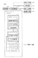
図11は、本発明の実施の形態2に係る画像加工装置200を示す構成図である。図11において、図1と同様の要素については同一の符号を付してしてあるので、それらのここでの詳細な説明は省略する。図11に示される画像加工装置200は、図1に示される画像加工装置100において、中央処理装置110と画像表示装置150との間に、画像加工処理を専ら行うグラフィックスエンジン170を設置したものである。
【0057】
グラフィックスエンジン170は、ジオメトリエンジン172と、レンダリングエンジン173と、テクスチャメモリ175と、フレームバッファ176と、Zバッファ177とを備える。ジオメトリエンジン172は、所定のプログラムに従って制御されることにより、屈曲境界線設定手段111と、ポリゴン加工手段112と、光源処理手段115として動作する機能を有する。レンダリングエンジン173は、所定のプログラムに従って制御されることにより、テクスチャ貼り付け手段113とフォグ処理手段114として動作する機能を有する。レンダリングエンジン173は、テクスチャメモリ175と、フレームバッファ176と、Zバッファ177とに接続されている。
【0058】
図2のステップS4〜S9においては、屈曲境界線設定手段111およびポリゴン加工手段112として動作するジオメトリエンジン172が、ポリゴン10〜40の変換を行う。即ち、座標変換された頂点座標が得られる。
【0059】
図2のステップS10においては、テクスチャ貼り付け手段113として動作するレンダリングエンジン173が、テクスチャメモリ175に格納されている原画像データであるテクスチャ50〜80の補間演算を行い、変換されたポリゴン10〜40に貼り付ける。画像表示装置150へのテクスチャ50〜80の表示は、テクスチャ50〜80の座標値および色値を、フレームバッファ176に書き込むことにより行われる。即ち、ジオメトリエンジン172により得られた座標変換後の頂点座標に対して、レンダリングエンジン173は、テクスチャメモリ175に既に格納しておいたテクスチャ50〜80を割り当てる。そして、ポリゴン内については、ディスプレイの解像度に相当する個々のピクセルの座標におけるテクスチャの位置を変換後の頂点座標から補間演算することで求め、その補間されたテクスチャ位置における色値をフレームバッファ176に書き込む。
【0060】
このときレンダリングエンジン173は、テクスチャ50〜80に対応するポリゴン10〜40の頂点のz座標値も補間演算してZバッファ176に書き込む。但し、書き込もうとするピクセルのz座標値が既に格納されているz座標値よりも小さくて、視点から奥行き方向に対しては既に手前にポリゴンの一部が存在して、書き込もうとするポリゴン上の部分は見えない位置にある場合には、書き込みを行わない。これによりレンダリングエンジン173は、視点に最も近い部分にある画像のみを、画像表示装置150に表示させることができる。
【0061】
また、レンダリングエンジン173がテクスチャ50〜80の補間演算を行う際には、座標値だけではなく色値についても、近傍のテクスチャの色値でフィルタリングして補間演算を行ってよい。これにより、滑らかに色が変化するテクスチャマッピングが可能となる。
【0062】
このように、本実施の形態に係る画像加工装置200は、画像加工処理を専ら行うグラフィックスエンジン170を備えているので、実施の形態1の効果に加えて、画像加工処理を高速に行うことができ、また、中央処理装置110において画像加工処理以外の処理を並行して行うことができる。実施の形態1で説明した画像加工処理は、3次元グラフィックス処理として一般的な、座標変換とテクスチャマッピングとの組み合わせによって成り立っているので、グラフィックスエンジン170として専用のハードウェアを持つことにより、上述したもの以外の3次元グラフィックス処理にも対応でき、様々な画像処理を行うことができる。
【0063】
【発明の効果】
以上、説明したように、請求項1に記載の発明に係る画像加工装置は、2次元画像を入力させる画像入力手段と、入力された前記2次元画像を記憶する画像記憶手段と、記憶された前記2次元画像上に屈曲境界線を設定する屈曲境界線設定手段と、設定された前記屈曲境界線に沿って前記2次元画像を指定された屈曲角度で3次元空間内において屈曲させるとともに、視線の深さ方向に対する回転を規定する所定の回転軸を中心として指定された回転角度で回転させた画像を作成する画像加工手段と、前記画像加工手段により作成された前記画像を表示する画像表示手段とを備えるので、簡単な処理で、ユーザの興味を持続させるような視覚的効果が得られる。
【図面の簡単な説明】
【図1】実施の形態1に係る画像加工装置の構成図である。
【図2】実施の形態1に係る画像加工方法を示すフローチャートである。
【図3】実施の形態1に係る加工前の顔画像を示す図である。
【図4】実施の形態1に係る顔画像の回転を示す図である。
【図5】実施の形態1に係る顔画像の平行移動を示す図である。
【図6】実施の形態1に係る顔画像の平行移動を示す図である。
【図7】実施の形態1に係る顔画像の回転を示す図である。
【図8】実施の形態1に係る顔画像の回転を示す図である。
【図9】実施の形態1に係る加工後の顔画像を示す図である。
【図10】実施の形態1に係る加工後の顔画像を示す図である。
【図11】実施の形態2に係る画像加工装置の構成図である。
【符号の説明】
10〜40 ポリゴン、11〜14,21〜24,31〜34,41〜44,51〜54,61〜64,71〜74,81〜84 点、50〜80 テクスチャ、100,200 画像加工装置、110 中央処理装置、111 屈曲境界線設定手段、112 ポリゴン加工手段、113 テクスチャ貼り付け手段、114 フォグ処理手段、115 光源処理手段、116 画像加工手段、120指示入力装置、130 画像入力装置、140 通信装置、150 画像表示装置、160 記憶装置、170 グラフィックスエンジン、172 ジオメトリエンジン、173 レンダリングエンジン、175 テクスチャメモリ、176 フレームバッファ、177 Zバッファ、500 顔画像、eL,eR,eM 座標、α 回転角、θ 屈曲角。[0001]
TECHNICAL FIELD OF THE INVENTION
The present invention relates to an image processing apparatus for deforming an image, and is particularly suitable for use in a mobile phone capable of processing a face image such as a face photograph.
[0002]
[Prior art]
As a method of processing a face image such as a face photograph in a conventional mobile phone, there are a method of performing tone conversion such as negative inversion and sepia conversion, and a method of adding an illustration or a frame and combining them. In these processing methods, the shape of the original image was not processed.
[0003]
As a method of processing the shape of an image in a computer or the like, there is a technique of texture mapping using three-dimensional graphics. In conventional texture mapping in a method of processing a face image such as a face photograph, a two-dimensional texture image is deformed only in a two-dimensional space, or a three-dimensional object model is constructed in a three-dimensional space to create a model. A method of attaching a two-dimensional texture image to each surface to be formed has been adopted. An example of such an image processing method is described in Patent Document 1, for example.
[0004]
[Patent Document 1]
JP 2000-172874 A
[Problems to be solved by the invention]
As described above, the method of processing a face image or a face photograph in a conventional mobile phone is basically performed only in a two-dimensional coordinate space, and thus it is difficult to maintain the interest of the user. There was a point.
[0006]
In addition, in order to maintain the interest of the user, a complicated model must be prepared, and there is a problem that an enormous amount of arithmetic processing is required for its processing.
[0007]
The present invention has been made to solve the above problems, and does not require a huge amount of arithmetic processing for preparation of a complicated model and its processing, and can maintain user's interest with simple processing. It is an object of the present invention to provide an image processing apparatus that can provide a visual effect and is suitable for handling a face image such as a face photograph.
[0008]
[Means for Solving the Problems]
The image processing device according to the first aspect of the present invention provides an image input device for inputting a two-dimensional image, an image storage device for storing the input two-dimensional image, and a bend on the stored two-dimensional image. A bent boundary line setting means for setting a boundary line, and bending the two-dimensional image in a three-dimensional space at a specified bending angle along the set bent boundary line, and rotating the line of sight in the depth direction. The image processing device includes image processing means for creating an image rotated at a designated rotation angle about a predetermined rotation axis to be defined, and image display means for displaying the image created by the image processing means.
[0009]
BEST MODE FOR CARRYING OUT THE INVENTION
<Embodiment 1>
FIG. 1 is a configuration diagram illustrating an
[0010]
FIG. 2 is a flowchart illustrating a processing procedure of image processing using the
[0011]
First, in step S1, a face image 500 as shown in FIG. 3 is input from the
[0012]
In step S2, in steps S5 to S7 described later, a bending angle θ for bending the face image 500 in the vertical direction (y-axis direction) is set by the user inputting from the
[0013]
In step S3, a rotation angle α for rotating the bent face image 500 in the depth direction of the user's line of sight about the x-axis in step S8 described later is set by the user inputting from the
[0014]
In step S4, the bending
[0015]
(Equation 1)
Sets the coordinates eM.
[0017]
The face image 500 is divided into four rectangles by a straight line x = 0.0, x = eL, x = eM, x = eR, x = 1.0. As shown in FIG. 3, when the z-axis is defined in a direction perpendicular to the xy plane, and the face image 500 is treated as a plane placed on the plane z = 0, the divided quadrilateral becomes four
[0018]
The coordinates of the vertices of the
[0019]
In steps S5 to S10 described below, the
[0020]
First, in the following steps S5 to S7, the polygon processing means 112 bends the face image 500 by θ in the vertical direction (y-axis direction). In steps S5 to S7, the face image 500 is bent so as to be convex along the straight line x = eL and the straight line x = eR and concave along the straight line x = eM.
[0021]
In step S5, as shown in FIG. 4, the polygon processing means 112 rotates the
[0022]
(Equation 2)
[Equation 3]
Due to the rotation of θ in step S5, the
(Equation 4)
(Equation 5)
(Equation 6)
Can be calculated by A matrix representing the coordinate transformation by the parallel movement can be expressed as shown in Expressions (7), (8), and (9) for the
[0029]
(Equation 7)
(Equation 8)
(Equation 9)
In step S6, the
[0033]
(Equation 10)
[Equation 11]
A matrix representing this coordinate transformation by parallel movement can be expressed as shown in equation (12) for
[0036]
(Equation 12)
In step S8, the
[0038]
(Equation 13)
In step S9, the polygon processing means 112 projects the
[0040]
[Equation 14]
In step S10, the texture pasting means 113
[0042]
In the above description of the process, the matrix representing the coordinate transformation is described one by one. However, when all the parameters involved in the coordinate transformation can be prepared as in the present embodiment, the
[0043]
In step S2 (S3), the user directly inputs the value of the bending angle θ (rotation angle α) from the
[0044]
In step S4, the bending
[0045]
In step S6, the rotation angle α of the face image 500 about the x axis is input by the user. The user not only inputs the rotation angle α, but also changes the rotation angle α of the face image 500 continuously. The operation mode can also be selected. Thus, the facial expression of the face image 500 can be continuously changed, and the user's interest can be maintained for a longer time.
[0046]
Prior to step S9, the user can select in step S8-1 to perform fog processing on the face image 500 using the fog processing means 114 for performing fog processing for further enhancing perspective. . The fog processing is a technique for changing a color tone of an object as shown in Expression (15) so that a portion far from the viewpoint is blurred.
[0047]
(Equation 15)
Here, f is the fog coefficient, Ci is the color of the object (the
[0049]
(Equation 16)
Further, prior to step S9, in step S8-2, the user performs a light source process (OpenGL Programming Guide P.3) for changing the color of the object or adding a highlight to the object as if the object has been hit by light. 188-P.192) can be selected. The light
[0051]
The drawing of the face image 500 is completed by the above steps S4 to S10. In step S11, it is checked whether or not the operation mode and parameters (bending angle θ and rotation angle α) have been changed by a user input from the
[0052]
In step S12, it is checked whether or not a user instruction to save the processed face image 500 has been made from the
[0053]
In step S13, it is checked whether or not a user instruction for replacing the original image, that is, the face image 500 before processing has been given from the
[0054]
In step S14, it is confirmed whether or not a user instruction to end this flow has been issued from the
[0055]
As described above, in the
[0056]
<
FIG. 11 is a configuration diagram showing an
[0057]
The
[0058]
In steps S4 to S9 in FIG. 2, the
[0059]
In step S10 in FIG. 2, the
[0060]
At this time, the
[0061]
Further, when the
[0062]
As described above, since the
[0063]
【The invention's effect】
As described above, the image processing apparatus according to the first aspect of the present invention has an image input unit for inputting a two-dimensional image, an image storage unit for storing the input two-dimensional image, and A bending boundary line setting means for setting a bending boundary line on the two-dimensional image, and bending the two-dimensional image at a specified bending angle in a three-dimensional space along the set bending boundary line; Image processing means for creating an image rotated at a specified rotation angle about a predetermined rotation axis defining rotation in the depth direction of the image, and image display means for displaying the image created by the image processing means Therefore, with a simple process, a visual effect that maintains the user's interest can be obtained.
[Brief description of the drawings]
FIG. 1 is a configuration diagram of an image processing apparatus according to a first embodiment.
FIG. 2 is a flowchart showing an image processing method according to the first embodiment.
FIG. 3 is a diagram showing a face image before processing according to the first embodiment;
FIG. 4 is a diagram showing rotation of a face image according to the first embodiment.
FIG. 5 is a diagram showing a parallel movement of a face image according to the first embodiment.
FIG. 6 is a diagram showing a parallel movement of a face image according to the first embodiment.
FIG. 7 is a diagram showing rotation of a face image according to the first embodiment;
FIG. 8 is a diagram showing rotation of a face image according to the first embodiment.
FIG. 9 is a diagram showing a face image after processing according to the first embodiment.
FIG. 10 is a diagram showing a face image after processing according to the first embodiment.
FIG. 11 is a configuration diagram of an image processing apparatus according to a second embodiment.
[Explanation of symbols]
10 to 40 polygons, 11 to 14, 21 to 24, 31 to 34, 41 to 44, 51 to 54, 61 to 64, 71 to 74, 81 to 84 points, 50 to 80 textures, 100, 200 image processing devices, 110 central processing unit, 111 bent boundary line setting unit, 112 polygon processing unit, 113 texture pasting unit, 114 fog processing unit, 115 light source processing unit, 116 image processing unit, 120 instruction input device, 130 image input device, 140 communication Device, 150 image display device, 160 storage device, 170 graphics engine, 172 geometry engine, 173 rendering engine, 175 texture memory, 176 frame buffer, 177 Z buffer, 500 face image, eL, eR, eM coordinates, α rotation angle , Θ bending angle.
Claims (9)
入力された前記2次元画像を記憶する画像記憶手段と、
記憶された前記2次元画像上に屈曲境界線を設定する屈曲境界線設定手段と、
設定された前記屈曲境界線に沿って前記2次元画像を指定された屈曲角度で3次元空間内において屈曲させるとともに、視線の深さ方向に対する回転を規定する所定の回転軸を中心として指定された回転角度で回転させた画像を作成する画像加工手段と、
前記画像加工手段により作成された前記画像を表示する画像表示手段と
を備える画像加工装置。Image input means for inputting a two-dimensional image,
Image storage means for storing the input two-dimensional image,
A bending boundary line setting means for setting a bending boundary line on the stored two-dimensional image;
The two-dimensional image is bent at a specified bending angle in a three-dimensional space along the set bending boundary line, and is specified around a predetermined rotation axis that defines rotation in the depth direction of the line of sight. Image processing means for creating an image rotated by a rotation angle,
An image display device for displaying the image created by the image processing device.
前記2次元画像は2次元顔画像であり、
前記屈曲境界線は、目の位置を含む前記2次元顔画像上の複数の位置に設定される画像加工装置。The image processing apparatus according to claim 1,
The two-dimensional image is a two-dimensional face image,
The image processing device, wherein the bending boundary is set at a plurality of positions on the two-dimensional face image including an eye position.
前記屈曲境界線設定手段が、
記憶された前記2次元画像の濃度分布から前記屈曲境界線の位置を算出する手段を備える画像加工装置。The image processing device according to claim 1 or 2, wherein:
The bending boundary line setting means,
An image processing apparatus comprising: means for calculating a position of the bending boundary line from a stored density distribution of the two-dimensional image.
前記回転角度は連続的に変化される
画像加工装置。An image processing apparatus according to claim 1, wherein:
An image processing apparatus wherein the rotation angle is continuously changed.
前記画像記憶手段が、入力された複数の前記2次元画像を記憶する画像加工装置。An image processing apparatus according to claim 1, wherein
An image processing device, wherein the image storage means stores the plurality of input two-dimensional images.
前記画像加工手段により作成された前記画像に対して光源処理を行う光源処理手段をさらに備える画像加工装置。The image processing apparatus according to claim 1, wherein:
An image processing apparatus further comprising light source processing means for performing light source processing on the image created by the image processing means.
前記画像加工手段により作成された前記画像に対してフォグ処理を行うフォグ処理手段
をさらに備える画像加工装置。The image processing apparatus according to claim 1, wherein:
An image processing apparatus further comprising fog processing means for performing fog processing on the image created by the image processing means.
前記画像加工装置により加工された前記2次元顔画像を送受信する通信手段
をさらに備える画像加工装置。The image processing apparatus according to claim 1, wherein:
An image processing device further comprising communication means for transmitting and receiving the two-dimensional face image processed by the image processing device.
前記画像入力手段により入力された前記2次元顔画像と、
前記屈曲角度と、
前記回転角度とからなるデータを送受信する通信手段をさらに備える画像加工装置。The image processing apparatus according to claim 1, wherein:
The two-dimensional face image input by the image input means;
The bending angle,
An image processing apparatus further comprising communication means for transmitting and receiving data comprising the rotation angle.
Priority Applications (3)
| Application Number | Priority Date | Filing Date | Title |
|---|---|---|---|
| JP2002366040A JP2004199301A (en) | 2002-12-18 | 2002-12-18 | Image processor |
| US10/454,506 US20040119723A1 (en) | 2002-12-18 | 2003-06-05 | Apparatus manipulating two-dimensional image in a three-dimensional space |
| DE10336492A DE10336492A1 (en) | 2002-12-18 | 2003-08-08 | Device for processing a two-dimensional image in a three-dimensional space |
Applications Claiming Priority (1)
| Application Number | Priority Date | Filing Date | Title |
|---|---|---|---|
| JP2002366040A JP2004199301A (en) | 2002-12-18 | 2002-12-18 | Image processor |
Publications (2)
| Publication Number | Publication Date |
|---|---|
| JP2004199301A true JP2004199301A (en) | 2004-07-15 |
| JP2004199301A5 JP2004199301A5 (en) | 2005-11-10 |
Family
ID=32588297
Family Applications (1)
| Application Number | Title | Priority Date | Filing Date |
|---|---|---|---|
| JP2002366040A Pending JP2004199301A (en) | 2002-12-18 | 2002-12-18 | Image processor |
Country Status (3)
| Country | Link |
|---|---|
| US (1) | US20040119723A1 (en) |
| JP (1) | JP2004199301A (en) |
| DE (1) | DE10336492A1 (en) |
Cited By (4)
| Publication number | Priority date | Publication date | Assignee | Title |
|---|---|---|---|---|
| WO2006041179A1 (en) * | 2004-10-15 | 2006-04-20 | Vodafone K.K. | Linking operation method, and communication terminal device |
| JP2007068133A (en) * | 2005-08-29 | 2007-03-15 | For-A Co Ltd | Three-dimensional image special effect instrument |
| JP2015136377A (en) * | 2014-01-20 | 2015-07-30 | 株式会社ニコン | Image processor |
| JP2016066327A (en) * | 2014-09-26 | 2016-04-28 | 株式会社Jvcケンウッド | Image processing device, image processing method and image processing program |
Families Citing this family (7)
| Publication number | Priority date | Publication date | Assignee | Title |
|---|---|---|---|---|
| JP4986279B2 (en) * | 2006-09-08 | 2012-07-25 | 任天堂株式会社 | GAME PROGRAM AND GAME DEVICE |
| US9326831B2 (en) * | 2006-10-20 | 2016-05-03 | Align Technology, Inc. | System and method for positioning three-dimensional brackets on teeth |
| CN102132091B (en) * | 2007-09-21 | 2013-10-16 | 皇家飞利浦电子股份有限公司 | Method of illuminating 3d object with modified 2d image of 3d object by means of projector, and projector suitable for performing such method |
| EP2447915A1 (en) * | 2010-10-27 | 2012-05-02 | Sony Ericsson Mobile Communications AB | Real time three-dimensional menu/icon shading |
| US20120197428A1 (en) * | 2011-01-28 | 2012-08-02 | Scott Weaver | Method For Making a Piñata |
| US9325936B2 (en) | 2013-08-09 | 2016-04-26 | Samsung Electronics Co., Ltd. | Hybrid visual communication |
| US10127725B2 (en) * | 2015-09-02 | 2018-11-13 | Microsoft Technology Licensing, Llc | Augmented-reality imaging |
Family Cites Families (6)
| Publication number | Priority date | Publication date | Assignee | Title |
|---|---|---|---|---|
| US5715385A (en) * | 1992-07-10 | 1998-02-03 | Lsi Logic Corporation | Apparatus for 2-D affine transformation of images |
| US6492986B1 (en) * | 1997-06-02 | 2002-12-10 | The Trustees Of The University Of Pennsylvania | Method for human face shape and motion estimation based on integrating optical flow and deformable models |
| JP2001216515A (en) * | 2000-02-01 | 2001-08-10 | Matsushita Electric Ind Co Ltd | Method and device for detecting face of person |
| US6960020B2 (en) * | 2001-08-31 | 2005-11-01 | Analogic Corporation | Image positioning method and system for tomosynthesis in a digital X-ray radiography system |
| US7246044B2 (en) * | 2000-09-13 | 2007-07-17 | Matsushita Electric Works, Ltd. | Method for aiding space design using network, system therefor, and server computer of the system |
| JP2002123160A (en) * | 2000-10-16 | 2002-04-26 | Sony Corp | Holographic stereogram printing order accepting system and method |
-
2002
- 2002-12-18 JP JP2002366040A patent/JP2004199301A/en active Pending
-
2003
- 2003-06-05 US US10/454,506 patent/US20040119723A1/en not_active Abandoned
- 2003-08-08 DE DE10336492A patent/DE10336492A1/en not_active Withdrawn
Cited By (8)
| Publication number | Priority date | Publication date | Assignee | Title |
|---|---|---|---|---|
| WO2006041179A1 (en) * | 2004-10-15 | 2006-04-20 | Vodafone K.K. | Linking operation method, and communication terminal device |
| JPWO2006041179A1 (en) * | 2004-10-15 | 2008-05-22 | ソフトバンクモバイル株式会社 | Linking operation method and communication terminal device |
| JP4722052B2 (en) * | 2004-10-15 | 2011-07-13 | ソフトバンクモバイル株式会社 | Linking operation method and communication terminal device |
| US8375079B2 (en) | 2004-10-15 | 2013-02-12 | Vodafone Group Plc | Coordinated operation method, and communication terminal device |
| JP2007068133A (en) * | 2005-08-29 | 2007-03-15 | For-A Co Ltd | Three-dimensional image special effect instrument |
| JP4626761B2 (en) * | 2005-08-29 | 2011-02-09 | 株式会社朋栄 | 3D image special effect device |
| JP2015136377A (en) * | 2014-01-20 | 2015-07-30 | 株式会社ニコン | Image processor |
| JP2016066327A (en) * | 2014-09-26 | 2016-04-28 | 株式会社Jvcケンウッド | Image processing device, image processing method and image processing program |
Also Published As
| Publication number | Publication date |
|---|---|
| DE10336492A1 (en) | 2004-07-15 |
| US20040119723A1 (en) | 2004-06-24 |
Similar Documents
| Publication | Publication Date | Title |
|---|---|---|
| JP3294149B2 (en) | Three-dimensional texture mapping processing device and three-dimensional image generation device using the same | |
| KR101145260B1 (en) | Apparatus and method for mapping textures to object model | |
| US10593096B2 (en) | Graphics processing employing cube map texturing | |
| US9367943B2 (en) | Seamless fracture in a production pipeline | |
| US8436852B2 (en) | Image editing consistent with scene geometry | |
| TWI478096B (en) | Three-dimensional graphics clipping method, three-dimensional graphics displaying method and graphics processing apparatus thereof | |
| JP3626144B2 (en) | Method and program for generating 2D image of cartoon expression from 3D object data | |
| JP2004199301A (en) | Image processor | |
| CN115810101A (en) | Three-dimensional model stylizing method and device, electronic equipment and storage medium | |
| RU2680355C1 (en) | Method and system of removing invisible surfaces of a three-dimensional scene | |
| CN113826144A (en) | Facial texture map generation using a single color image and depth information | |
| JPH09330423A (en) | Three-dimensional shape data transforming device | |
| JP3459401B2 (en) | Stereoscopic image generation method using Z buffer | |
| US5793372A (en) | Methods and apparatus for rapidly rendering photo-realistic surfaces on 3-dimensional wire frames automatically using user defined points | |
| JP2003115055A (en) | Image generator | |
| JP5165819B2 (en) | Image processing method and image processing apparatus | |
| JP4060375B2 (en) | Spotlight characteristic forming method and image processing apparatus using the same | |
| JPWO2019049457A1 (en) | Image generating apparatus and image generating method | |
| KR20100075351A (en) | Method and system for rendering mobile computer graphic | |
| CN110335335A (en) | Uniform density cube for spherical projection renders | |
| KR20080064523A (en) | 3-dimension graphic processing apparatus and operating method thereof | |
| US7656408B1 (en) | Method and system for animating a border | |
| JP2000057372A (en) | Image processor, image processing method and storage medium | |
| US10453247B1 (en) | Vertex shift for rendering 360 stereoscopic content | |
| JP2004054634A (en) | Picture processor and its method |
Legal Events
| Date | Code | Title | Description |
|---|---|---|---|
| A521 | Written amendment |
Free format text: JAPANESE INTERMEDIATE CODE: A523 Effective date: 20050916 |
|
| A621 | Written request for application examination |
Free format text: JAPANESE INTERMEDIATE CODE: A621 Effective date: 20050916 |
|
| A977 | Report on retrieval |
Free format text: JAPANESE INTERMEDIATE CODE: A971007 Effective date: 20080529 |
|
| A131 | Notification of reasons for refusal |
Free format text: JAPANESE INTERMEDIATE CODE: A131 Effective date: 20080610 |
|
| A02 | Decision of refusal |
Free format text: JAPANESE INTERMEDIATE CODE: A02 Effective date: 20081014 |