JP2004197891A - Change gear ratio controller and leading car follow-up controller - Google Patents
Change gear ratio controller and leading car follow-up controller Download PDFInfo
- Publication number
- JP2004197891A JP2004197891A JP2002369697A JP2002369697A JP2004197891A JP 2004197891 A JP2004197891 A JP 2004197891A JP 2002369697 A JP2002369697 A JP 2002369697A JP 2002369697 A JP2002369697 A JP 2002369697A JP 2004197891 A JP2004197891 A JP 2004197891A
- Authority
- JP
- Japan
- Prior art keywords
- preceding vehicle
- candidate
- speed
- vehicle
- command value
- Prior art date
- Legal status (The legal status is an assumption and is not a legal conclusion. Google has not performed a legal analysis and makes no representation as to the accuracy of the status listed.)
- Pending
Links
Images


Abstract
Description
【0001】
【発明の属する技術分野】
本発明は、変速機の変速比を制御する変速比制御装置、及び先行車に基づいて自車速を制御する先行車追従制御装置に関する。
【0002】
【従来の技術】
従来、先行車追従制御装置としては、特許文献1に記載されている技術がある。特許文献1に記載されている先行車追従制御装置は、車間距離センサを所定角度範囲で回動させることで、追従対象の先行車(制御対象)との車間距離LYを検出するとともに、変更先の追従対象先行車との車間距離Lを検出している。さらに、この先行車追従制御装置は、追従対象先行車との相対速度ΔVも測定している。
【0003】
そして、この先行車追従制御装置は、車間距離LY及び相対速度ΔVに基づいて追従対象先行車の変更を検出した場合に、変更先の追従対象先行車の車幅方向変化速度VXを測定して、この測定した車幅方向変化速度VXに基づいて追従対象先行車の変更制御ゲインKLCを算出している。そして、車両用追従走行制御装置は、このように算出した変更制御ゲインKLCを通常制御ゲインKLUに代えて制御ゲインとして設定し、車間距離演算処理の感度を車幅方向変化速度VXに応じて変更するようにすることで、割込み又は自車両の車線変更時の追従制御を最適状態に調整している。
【0004】
【特許文献1】
特開2002−87109号公報
【0005】
【発明が解決しようとする課題】
しかしながら、自車速を目標車速(車間距離制御部で演算された演算値)に一致させるような先行車追従制御装置の場合は、車両の急な割込みに対し、変速比を低速側に変更してエンジンブレーキを大きくすることが考えられる。しかし、変速機の変速比変更動作には所定の応答時間が必要である、といった場合がある。
本発明は、前述の実情に鑑みてなされたものであり、車両が割り込んできた場合でも、迅速かつ十分に制動力を発生させることができる変速比制御装置及び先行車追従制御装置の提供を目的とする。
【0006】
【課題を解決するための手段】
前述の問題を解決するために、請求項1記載の発明に係る変速比制御装置は、将来先行車になるであろう先行車候補と自車両との接近状態に基づいて、自車両の変速比を変化させる。
また、請求項6記載の発明に係る先行車追従制御装置は、走行制御の制御対象になるであろう先行車候補と自車両との接近状態に基づいて、自車両の変速比を変化させる。
【0007】
また、請求項7記載の発明に係る先行車追従制御装置は、自車両と制御対象としての先行車との間の位置関係に基づいて目標車速を算出する目標車速算出手段と、前記目標車速算出手段に合致するように自車速を制御する車速制御手段とを備えており、前記制御対象になるであろう先行車候補を先行車候補検出手段により検出し、前記先行車候補検出手段が検出した先行車候補と自車両との接近状態を接近状態検出手段により検出し、前記接近状態検出手段が検出した前記接近状態に基づいて、自車両の変速比を変速比変更手段により変更する。
【0008】
【発明の効果】
請求項1記載の変速比制御装置によれば、運転者が先行車を認識し、アクセルを戻すことで、迅速かつ十分な制動力を得ることができる。
また、請求項6及び7に記載の先行車追従制御装置によれば、先行車候補が後に割り込みなどをした結果、走行制御の制御対象になった場合でも、迅速かつ十分な制動力を得ることができる。
【0009】
【発明の実施の形態】
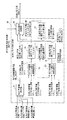
以下、本発明の実施の形態を図面を参照しながら詳細に説明する。この実施の形態は、先行車追従制御装置である。図1は先行車追従制御装置及びその先行車追従制御装置にかかる構成を、ブロック図として示す。以下、図1に示す各ブロックの構成と動作を説明する。
【0010】
先行車追従制御装置30は、車速指令最大値設定部31、車間距離制御部32、車速指令値決定部33、駆動トルク指令値算出部34、実変速比算出部35及び駆動トルク指令値分配部40を備えている。先行車追従制御装置30のこのような構成は、マイクロコンピュータとその周辺部品として構成されている。また、先行車追従制御装置30内部のブロックはコンピュータの演算処理内容をブロックに別けて表示したものであり、各ブロックにおいて一定の制御周期毎に演算を実行する。
【0011】
この先行車追従制御装置30には、セットスイッチ(SET SW)11、アクラレートスイッチ(ACC SW)12、コーストスイッチ(COAST SW)13、車速センサ14、車間時間設定部15、車間距離センサ16及びエンジン回転数センサ17からの各種信号が入力されている。ここで、車間距離センサ16には、操舵各センサ18からの信号が入力されている。また、先行車追従制御装置30は、先行車追従制御装置20は各種処理結果に基づいて、無段変速機コントローラ21及びエンジン出力コントローラ22に各種信号を出力している。
【0012】
車速センサ14は、タイヤの回転数等から自車度VAを検出し、この検出した自車度VAを先行車追従制御装置30及び車間距離センサ16に出力する。
車間時間設定部15は、運転者が車間時間dTを設定する部分である。例えば、車間時間設定部15は、例えば遠距離、中距離、近距離の3段階に切り換えるスイッチを備えており、運転者がこれらスイッチを操作して3種の車間時間を選択できるように構成されている。ここで、車間時間とは、先行車が停止した場合に、自車両が現在の速度で先行車に到達するまでの時間をいう。また、自車両と先行車との間の距離が近く設定されれば、dTは小さな値になる。この車間時間設定部15は、設定された車間時間dTを先行車追従制御装置30の車間距離制御部32に出力する。
【0013】
車間距離センサ16は、例えばーザレーダを利用し、光や電波の反射波によって、自車両と先行車との間の車間距離LAを計測する。さらに、車間距離センサ16は、計測した車間距離LAの時間変化から相対速度ΔVを検出する。そして、車間距離センサ16は、図2中(A)及び(B)に示すように、所定角度αの範囲内で回動する、いわゆるスキャン機構を備えることで、自車両500が走行する車線に存在する先行車501の他に、自車両が走行する車線の両隣の車線に存在する先行車502,503についても、車間距離や相対速度を検出することができるようになっている。車間距離センサ16に操舵角センサ18からの操舵角信号φが入力されており、車間距離センサ16は、この操舵角信号に連動して、自車両前方に対して回動する範囲が変化するようになっている。例えば、車間距離センサ16のスキャン方向を操舵角センサの操舵角信号に基づいて行う技術としては、特開2001−246962号公報に記載されている技術がある。
【0014】
ここで、車間距離センサ16が検出する値を、図2を用いて説明する。図2中(A)は、自車両と先行車との間の車間距離を説明する図であり、図2中(B)は、自車両と先行車との間の相対速度を説明する図である。
車間距離センサ16は、自車両500が走行する車線に存在する先行車(車両前方の対象物ともいえる。以下、自車線先行車という。)501との間の車間距離LA及び相対速度ΔVを検出する。そして、車間距離センサ16は、この車間距離LA及び相対速度ΔVを先行車追従制御装置30の車間距離制御部32に出力する。また、車間距離センサ16には、車速センサ14からの自車速VAが入力されており、前記相対速度ΔVと自車速VAとの差分が所定値の範囲外にある場合、自車線先行車501を制御対象としての「先行車」であると判断する。そして、車間距離センサ16は、自車線先行車501を「先行車」と判断した場合、"1"にした先行車認識フラグFを先行車追従制御装置30の車間距離制御部32に出力する。なお、車間距離センサ16は、制御対象の「先行車」の認識をすることができない場合、"0"の先行車認識フラグFを先行車追従制御装置30の車間距離制御部32に出力する。ここで、前記所定値とは、例えば±5%×VAkm/hである。
【0015】
また、車間距離センサ16は、右車線に存在する先行車(以下、右車線先行車という。)502と自車両500との間の車間距離(以下、右車線先行車候補車間距離という。)L1A_R 、自車両500とその右車線先行車502との間のX方向相対速度(以下、右車線先行車候補X方向相対速度という。)ΔV1X_R及びY方向相対速度(以下、右車線先行車候補Y方向相対速度という。)ΔV1Y_R、さらに、左車線に存在する先行車(以下、左車線先行車という。)503と自車両500との間の車間距離(以下、左車線先行車候補車間距離という。)L1A_L、自車両500とその左車線先行車503との間のX方向相対速度(以下、左車線先行車候補X方向相対速度という。)ΔV1X_L、Y方向相対速度(以下、左車線先行車候補X方向相対速度という。)ΔV1Y_Lを検出する。ここで、Y方向は自車両の走行方向であり、X方向はY方向に直交する方向である。
【0016】
そして、車間距離センサ16は、前述の右車線先行車候補車間距離L1A_R、右車線先行車候補X方向相対速度ΔV1X_R及び右車線先行車候補Y方向相対速度ΔV1Y_R、並びに左車線先行車候補車間距離L1A_L、左車線先行車候補X方向相対速度ΔV1X_L及び左車線先行車候補Y方向相対速度ΔV1Y_Lを先行車追従制御装置30の駆動トルク指令値分配部40に出力する。
【0017】
さらに、車間距離センサ16は、右車線先行車候補Y方向相対速度検出値ΔV1Y_Rと自車速VAとの差分が所定値の範囲外にある場合、右車線先行車502を将来制御対象になるであろう「先行車候補」と判断する。そして、車間距離センサ16は、右車線先行車502を「先行車候補」と判断した場合、"1"にした右車線先行車候補認識フラグFRを先行車追従制御装置30の駆動トルク指令値分配部40に出力する。また、左車線先行車503に関しても同様に、車間距離センサ16は、左車線先行車候補Y方向相対速度検出値ΔV1Y_Lと自車速VAとの差分が所定値の範囲外にある場合、左車線先行車503を将来制御対象になるであろう「先行車候補」と判断する。そして、車間距離センサ16は、左車線先行車503を「先行車候補」と判断した場合、"1"にした左車線先行車候補認識フラグFLを先行車追従制御装置30の駆動トルク指令値分配部40に出力する。なお、車間距離センサ16は、右車線について「先行車候補」を検出できない場合、右車線先行車候補認識フラグFRを"0"にして、また、左車線について「先行車候補」の検出できない場合、左車線先行車候補認識フラグFLを"0"にして、それらフラグFR、FLを先行車追従制御装置30の車間距離制御部32に出力する。また、前記所定値とは、例えば±5%×VAkm/hである。
【0018】
エンジン回転センサ17は、エンジン回転数NEを検出し、この検出したエンジン回転数NEを先行車追従制御装置30の実変速比算出部35に出力する。
先行車追従制御装置30は、前述したように、車速指令最大値設定部31、車間距離制御部32、車速指令値決定部33、駆動トルク指令値算出部34、実変速比算出部35及び駆動トルク指令値分配部40を備えている。
【0019】
ここで、車速指令最大値設定部31、車速指令値決定部33、実変速比算出部35、駆動トルク指令値算出部36については、本発明の要旨に影響しない限りどのような構成でも可能であり、例えば特開2001−328453号公報に開示されている技術と同様である。その概略は以下のようになる。なお、以下の説明では、(t)を付した符号は時間的に変化する値であることを意味し、必要に応じて(t)を付して表記している。
【0020】
車速指令最大値設定部31は、自車速VAの車速指令最大値Vsmax(目標車速)を設定する。具体的には、車速指令最大値設定部31は、セットスイッチ11が押されたときの自車速VAを車速指令最大値Vsmax(目標車速)として設定する。また、車速指令最大値設定部31は、セットスイッチ11によって車速指令最大値Vsmaxが設定された後、コーストスイッチ13が1回押される毎に、車速指令最大値Vsmaxを5km/hずつ低い値に設定する。また、車速指令最大値設定部31は、セットスイッチ11によって車速指令最大値Vsmaxが設定された後、アクセラレートスイッチ12が1回押される毎に、車速指令最大値Vsmaxを5km/hずつ高い値に設定する。車速指令最大値設定部31は、このように設定した車速指令最大値Vsmaxを車速指令値決定部33に出力する。
【0021】
車間距離制御部32は、車間制御用車速指令値V*を算出するように構成されている。具体的には次のように車間制御用車速指令値V*を算出する。
この車間距離制御部32には、自車速VA、車間時間dT、先行車認識フラグF、車間距離LA及び相対速度ΔVが入力されている。先ず、車間距離制御部32は、車間時間dT(t)、自車速VA(t)、相対速度ΔV(t)を用いて、下記(1)式により車間距離指令値L*(t)を算出する。
【0022】
L*(t)=(VA(t)+ΔV(t))×dT(t) ・・・(1)
次に、車間距離制御部32は、入力された先行車認識フラグF、相対速度ΔV及び車間距離LAに基づいて次のような演算を行う。
車間距離制御部32は、先行車を認識したときの相対速度ΔV及び車間距離LAを目標相対速度ΔVT(t)及び目標車間距離LT(t)の初期値とし、下記(2)式に示すフィルタにより、入力を前記車間距離指令値L*(t)とした場合における目標車間距離LT(t)と目標相対速度ΔVT(t)とを算出する。先行車認識フラグFは、例えば算出タイミングに用いる。
【0023】
【数1】

ここで、ωnTは目標車間距離応答の固有振動数である。また、設計者が任意に設定する値ζTは目標車間距離応答の減衰係数であり、設計者が任意に設定する値を示す前記(2)式について、車間距離指令値L*(t)を入力、目標車間距離LT(t)を出力とした場合の伝達関数は下記(3)式で示される。
LT(t)=ωnT 2・e−LV・s・L*(t)/(s2+2ζT・ωnT・s+ωnT 2) ・・・(3)
次に、車間距離制御部32は、車速制御部の無駄時間を無視した伝達特性GV(s)'を下記(4)式により算出する。
【0025】
GV(s)'=1/(TV・s+1) ・・・(4)
ここで、車速制御部は、例えば特開2001−328453号公報の記載に対応すれば、例えば車速指令最大値設定部31、車速指令値決定部33、駆動トルク指令値算出部34、実変速比算出部35及び駆動トルク指令値分配部40の部分に該当する。
【0026】
そして、車間距離制御部32は、この伝達特性GV(s)'と積分器との積からなる伝達関数の逆系と、前記LT(t)を得る前記(3)式の無駄時間を無視した伝達関数との積からなり、下記(5)式によりVC(t)を算出する。
VC(t)=ωnT 2・s(TV・s+1)・L*(t)/(s2+2ζT・ωnT・s+ωnT 2) ・・・(5)
また、前記(2)式を用いて状態空間表現からVC(t)を求めると、下記(6)式に示すようになる。
【0027】
【数2】
ここで、TVは、前述の車速制御部の伝達特性で使用する時定数である。
そして、車間距離制御部32は、実車間距離LA(t)、自車速VA(t)、相対速度ΔV(t)、目標車間距離LT(t)、目標相対速度ΔVT(t)、補正車速指令値VC(t)、及び定数fL、fVを用いて、下記(7)式により車間制御用車速指令値V*(t)を算出する。
【0029】
V*(t)=VA(t)+ΔV(t)−VC(t)−{LT(t)−LA(t)}・fL−{ΔVT(t)−ΔV(t)}・fV ・・・(7)
ここで、定数fL、fVは、いわゆるフィードバック定数であり、例えば特開2001−328453号公報に開示されているように算出される値である。
車間距離制御部32は、以上のようにして自車速VA、車間時間dT、先行車認識フラグF、車間距離LA及び相対速度ΔVに基づいて車間制御用車速指令値V*を算出する。そして、車間距離制御部32は、算出した車間制御用車速指令値V*を車速指令値決定部33に出力する。
【0030】
車速指令値決定部33は、入力された車間制御用車速指令値V*及び車速指令最大値Vsmaxに基づいて車速指令値VCOMを算出する。すなわち例えば、車速指令値決定部33は、車速指令最大値Vsmaxを上限として車間制御用車速指令値V*に基づいて車速指令値VCOMを算出する。そして、車速指令値決定部33は、算出した車速指令値VCOMを駆動トルク指令値決定部33に出力する。
【0031】
駆動トルク指令値算出部34は、入力された車速指令値VCOM及び自車速VAに基づいて駆動トルク指令値dFCを算出する。
ここで、車速指令値VCOM(t)を入力とし、自車速VA(t)を出力とした場合の伝達特性GV(s)を下記(8)式で表すことができる。
GV(s)=1/(TV・s+1)・e(−Lv・s) ・・・(8)
ここで、TVは1次遅れ時定数であり、LVはパワートレイン系の遅れによる無駄時間である。
【0032】
また、駆動トルク指令値dFC(t)を操作量とし、自車速VA(t)を制御量としてモデル化することによって、車両のパワートレインの挙動は、下記(9)式に示す簡易線形モデルとしての制御対象の車両モデルにより表すことができる。
VA(t)=1/(mV・Rt・s)・e(−Lv・s)・dFC(t) ・・・(9)
ここで、Rtはタイヤの有効回転半径であり、mVは車両質量である。このように駆動トルク指令値dFC(t)を入力とし、自車速VA(t)を出力とする車両モデルは、1/sの形となるので積分特性を有することになる。
【0033】
駆動トルク指令値算出部34は、以上のような関係に基づいて入力された車速指令値VCOM及び自車速VAを用いて駆動トルク指令値dFCを得る。そして、駆動トルク指令値算出部34は、駆動トルク指令値dFCを駆動トルク指令値分配部40に出力する。
駆動トルク指令値分配部40には、前述したように、右車線先行車候補車間距離L1A_R 、右車線先行車候補X方向相対速度ΔV1X_R、右車線先行車候補Y方向相対速度ΔV1Y_R及び右車線先行車候補認識フラグFR、並びに左車線先行車候補車間距離L1A_L、左車線先行車候補X方向相対速度ΔV1X_L、左車線先行車候補Y方向相対速度ΔV1Y_L及び左車線先行車候補認識フラグFLが入力されている。また、駆動トルク指令値分配部40には、車速センサ14からの自車両VA、駆動トルク指令値算出部34からの駆動トルク指令値dFC及び実変速比算出部35からの実変速比RATIOが入力されている。
【0034】
この駆動トルク指令値分配部40は、以上のような各種信号に基づいて変速比指令値DRATIO及びエンジン出力トルク指令値TECOMを算出し、この算出した変速比指令値DRATIOを無段変速機コントローラ21に出力し、また、エンジン出力トルク指令値TECOMをエンジン出力コントローラ22に出力している。
以下に駆動トルク指令値分配部40の詳細を説明する。
【0035】
駆動トルク指令値分配部40は、図3に示すように、変速比指令値設定部41、エンジントルク指令値算出部42及び変速比指令値補正部50を備えている。エンジントルク指令値算出部42には、駆動トルク指令値dFC及び実変速比RATIOが入力されており、この駆動トルク指令値dFC及び実変速比RATIOを用いて下記(11)式によりエンジントルク指令値TECOMを算出する。
【0036】
TECOM=dFC/(Gf・RATIO) ・・・(11)
ここで、Gfはファイナルギア比である。
駆動トルク指令値分配部40は、このエンジントルク指令値算出部42により算出したエンジントルク指令値TECOMをエンジン出力コントローラ22の出力する。エンジン出力コントローラ22では、このエンジン出力トルク指令値TECOMに基づいてエンジン出力の制御をする。
【0037】
変速比指令値設定部41は、車速と変速比との関係を、駆動トルクをパラメータとしたマップを有している。図4は、そのマップの例を示す。この変速比指令値設定部41には、自車速VAと駆動トルク指令値dFCが入力されており、変速比指令値設定部41は、前記マップを用いて、自車速VAと駆動トルク指令値dFCと対応する変速比を示す変速比指令値を算出する。なお、後述するが、本実施の形態では、変速比指令値DRATIOを補正しており、このようなことから、この変速比指令値設定部41が得る値は、補正前の変速比指令値(以下、補正前変速比指令値という。)DRATIO0となっている。変速比指令値設定部41は、このように算出した補正前変速比指令値DRATIO0を変速比指令値補正部50に出力する。
【0038】
変速比指令値補正部50は、自車両或いは自車線の左右の車線を走行している車両の状況から自車線への車両の割込みが予想される場合は、変速比指令値を大なる側(低速側)に変更するように構成されている。
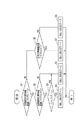
この変速比指令値補正部50は、図5に示すように、先行車候補選択部51、先行車候補X方向相対速度選択部52、先行車候補Y方向相対速度選択部53、変速比指令値補正マップ部(X方向)(以下、変速比指令値X方向補正マップ部という。)54、先行車候補X方向相対速度変化量演算部55、変速比指令値補正マップ部(Y方向)(以下、変速比指令値Y方向補正マップ部という。)56、変速比補正演算部60及び変速比指令値補正マップ部(X方向変化量)(以下、変速比指令値X方向変化量補正マップ部という。)57を備えている。
【0039】
先行車候補選択部51には、左車線先行車候補認識フラグFL、右車線先行車候補認識フラグFR、左車線先行車候補車間距離L1A_L及び右車線先行車候補車間距離L1A_Rが入力されている。先行車候補選択部51は、これら入力値に基づいて最終的な制御対象とする先行車を選択し、その選択結果を選択値(以下、先行車候補選択値という。)OBJ_SELECTとして出力する。
【0040】
具体的には、先行車候補選択部51は、自車両の左右どちらの車線に先行車候補が存在するか否かを判定する。先行車候補選択部51は、両車線に先行車候補が存在すると判定した場合は、車間距離が短い方を先行車候補とする。また、先行車候補選択部51は、両車線に先行車候補が存在すると判定した場合でかつその各車両との車間距離が同じである場合、右車線を走行している車両を強制的に先行車候補に決定する。そして、先行車候補選択部51は、そのような判断結果に基づいて、先行車候補がなしの場合、先行車候補選択値OBJ_SELECTを"0"にして、または、右車線を走行している先行車が先行車候補になる場合、先行車候補選択値OBJ_SELECTを"1"にして、または、左車線を走行している先行車が先行車候補になる場合、先行車候補選択値OBJ_SELECTを"2"にする。
【0041】
ここで、図6は、そのような先行車候補選択部51の先行車候補選択値OBJ_SELECTの設定処理の具体的な手順を示す。この図6を用いて、さらに具体的に説明する。
先ずステップS1において、先行車候補選択部51は、左車線先行車候補認識フラグFLが1であるか否か、すなわち左車線の先行車を先行車候補として認識しているか否かを判定する。ここで、先行車候補選択部51は、左車線先行車候補認識フラグFLが1の場合、ステップS2に進み、左車線先行車候補認識フラグFLが0の場合、すなわち左車線について先行車候補なしと判断した場合、ステップS6に進む。
【0042】
ステップS2では、先行車候補選択部51は、右車線先行車候補認識フラグFRが1であるか否か、すなわち右車線の先行車を先行車候補として認識しているか否かを判定する。ここで、先行車候補選択部51は、右車線先行車候補認識フラグFRが1の場合、ステップS3に進み、左車線先行車候補認識フラグFRが0の場合、すなわち右車線について先行車候補なしと判断した場合、ステップS5に進む。
【0043】
ステップS3は、左右の両車線の先行車を先行車候補として認識している場合のステップである。このステップS3では、先行車候補選択部51は、左車線先行車候補車間距離L1A_Lと、右車線先行車候補車間距離L1A_Rとを比較する。ここでは、先行車候補選択部51は、右車線先行車候補車間距離L1A_Rが左車線先行車候補車間距離L1A_L以下か否かを判定している。ここで、先行車候補選択部51は、右車線先行車候補車間距離L1A_Rが左車線先行車候補車間距離L1A_L以下の場合、ステップS4に進み、右車線先行車候補車間距離L1A_Rが、左車線先行車候補車間距離L1A_Lよりも大きい場合、ステップS5に進む。
【0044】
ステップS4では、先行車候補選択部51は、先行車候補選択値OBJ_SELECT を"1"にして(OBJ_SELECT=1)、すなわち自車線の右側車線を走行している先行車候補を最終的な先行車候補とし、当該処理を終了する。
ステップS5では、先行車候補選択部51は、先行車候補選択値OBJ_SELECT を"2"にして(OBJ_SELECT=2)、すなわち自車線の左側車線を走行している先行車候補を最終的な先行車候補とし、当該処理を終了する。
【0045】
また、前記ステップS1において左車線先行車候補認識フラグFLが0の場合に進むステップS6では、先行車候補選択部51は、右車線先行車候補認識フラグFRが1であるか否か、すなわち右車線に先行車の候補を認識中であるか否かを判定する。ここで、先行車候補選択部51は、右車線先行車候補認識フラグFRが1の場合、ステップS7に進み、左車線先行車候補認識フラグFRが0の場合、すなわち右車線について先行車候補なしと判断した場合、ステップS8に進む。
【0046】
ステップS7では、先行車候補選択部51は、先行車候補選択値OBJ_SELECT を"1"にして(OBJ_SELECT=1)、すなわち自車線の右側車線を走行している先行車候補を最終的な先行車候補とし、当該処理を終了する。
ステップS8では、先行車候補選択部51は、先行車候補選択値OBJ_SELECT を"0"にして(OBJ_SELECT=0)、すなわち自車線の左右両側車線について先行車候補がなしとし、当該処理を終了する。
【0047】
先行車候補選択部51は、以上の処理手順により、先行車候補選択値OBJ_SELECTを決定する。そして、先行車候補選択部51は、このようにして決定した先行車候補選択値OBJ_SELECTを、先行車候補X方向相対速度選択部52、先行車候補Y方向相対速度選択部53及び先行車候補X方向相対速度変化量演算部55に出力する。
【0048】
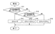
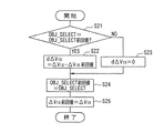
先行車候補X方向相対速度選択部52には、先行車候補選択値OBJ_SELECTの他、左車線先行車候補X方向相対速度ΔV1X_L及び右車線先行車候補X方向相対速度ΔV1X_Rが入力されている。先行車候補X方向相対速度選択部52は、これら入力値に基づいて先行車候補X方向相対速度ΔV1Xを算出する。図7は、その算出処理の処理手順を示す。
【0049】
先ずステップS11において、先行車候補X方向相対速度選択部52は、先行車候補選択値OBJ_SELECTが0か否か、すなわち先行車候補がなしか否かを判定する。ここで、先行車候補X方向相対速度選択部52は、先行車候補選択値OBJ_SELECTが0の場合、ステップS12に進み、先行車候補選択値OBJ_SELECTが0でない場合、ステップS13に進む。
【0050】
ステップS12では、先行車候補X方向相対速度選択部52は、先行車候補X方向相対速度ΔV1Xを0にして、当該処理を終了する。
ステップS13では、先行車候補X方向相対速度選択部52は、先行車候補選択値OBJ_SELECTが1か否か、すなわち自車線の右側車線を走行している先行車候補が最終的な先行車候補になったか否かを判定する。ここで、先行車候補X方向相対速度選択部52は、先行車候補選択値OBJ_SELECTが1の場合、ステップS14に進み、先行車候補選択値OBJ_SELECTが1でない場合、すなわち先行車候補選択値OBJ_SELECTが2の場合、ステップS15に進む。
【0051】
ステップS14では、先行車候補X方向相対速度選択部52は、先行車候補X方向相対速度ΔV1Xを右車線先行車候補X方向相対速度ΔV1X_Rにして、当該処理を終了する。
ステップS15では、先行車候補X方向相対速度選択部52は、先行車候補X方向相対速度ΔV1Xを左車線先行車候補X方向相対速度ΔV1X_Lにして、当該処理を終了する。
【0052】
先行車候補X方向相対速度選択部52は、以上のような処理手順により、先行車候補X方向相対速度ΔV1Xを算出する。そして、先行車候補X方向相対速度選択部52は、算出した先行車候補X方向相対速度ΔV1Xを変速比指令値X方向補正マップ部54及び先行車候補X方向相対速度変化量演算部55に出力する。
【0053】
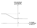
変速比指令値X方向補正マップ部54は、入力された先行車候補X方向相対速度ΔV1Xに基づいて、X方向についての変速比指令値補正値(以下、変速比指令値X方向補正値という。)DRATIO_HOSEI_Xを決定する。変速比指令値X方向補正マップ部54は、マップをもとに、先行車候補X方向相対速度ΔV1Xに基づいて変速比指令値X方向補正値DRATIO_HOSEI_Xを決定しており、図8は、そのマップの例を示す。
【0054】
図8に示すマップでは、先行車候補X方向相対速度ΔV1Xが0近傍又はそれ以上の場合、すなわち、X方向(自車両の走行方向の直交方向)において自車速と先行車候補速度とが同等か又は先行車候補速度の方が大きい場合、変速比指令値X方向補正値DRATIO_HOSEI_Xを1にする。ここで、X方向において自車速と先行車候補速度とが同等か又は先行車候補速度の方が大きい場合とは、X方向において自車両と先行車候補との近づく程度が小さいか、自車両と走行車候補とが離れていく場合である。
【0055】
また、先行車候補X方向相対速度ΔV1Xが前記0近傍よりも小さい場合、すなわち先行車候補速度よりも自車速の方が大きく、自車両が先行車候補に近づく程度が大きい場合、先行車候補X方向相対速度ΔV1Xが負の方向に大きくなるにしたがい、変速比指令値X方向補正値DRATIO_HOSEI_Xを1から増加させ、さらに、先行車候補X方向相対速度ΔV1Xがある負の値になった以降では、変速比指令値X方向補正値DRATIO_HOSEI_Xを1.5にする。
【0056】
変速比指令値X方向補正マップ部54はこのように先行車候補X方向相対速度ΔV1Xに基づいて変速比指令値X方向補正値DRATIO_HOSEI_Xを得ており、この変速比指令値X方向補正値DRATIO_HOSEI_Xは変速比補正演算部60に出力される。
先行車候補X方向相対速度変化量演算部55は、入力された先行車候補選択値OBJ_SELECT及び先行車候補X方向相対速度ΔV1Xに基づいて先行車候補X方向相対速度変化量dΔV1Xを算出する。図9は、その算出処理の処理手順を示す。
【0057】
先ずステップS21において、先行車候補X方向相対速度変化量演算部55は、先行車候補選択値OBJ_SELECTと当該先行車候補選択値OBJ_SELECTの前回値とが同じか否かを判定する。ここで、先行車候補X方向相対速度変化量演算部55は、それが同じである場合、すなわち先行車候補の変更がない場合、ステップS22に進み、それが異なる場合、すなわち先行車候補が変更している場合、ステップS23に進む。
【0058】
ステップS22では、先行車候補X方向相対速度変化量演算部55は、下記(12)式により、先行車候補X方向相対速度変化量dΔV1Xを算出する。
dΔV1X=ΔV1X−ΔV1X前回値 ・・・(12)
この先行車候補X方向相対速度変化量dΔV1Xは、自車両と先行車候補とのX方向の位置の変化量を示す値になる。
【0059】
先行車候補X方向相対速度変化量演算部55は、このようにして先行車候補X方向相対速度変化量dΔV1Xを算出し、ステップS24に進む。
ステップS23では、先行車候補X方向相対速度変化量演算部55は、先行車候補X方向相対速度変化量dΔV1Xを0にする(dΔV1X=0)。そして、先行車候補X方向相対速度変化量演算部55は、ステップS24に進む。
【0060】
ステップS24では、先行車候補X方向相対速度変化量演算部55は、先行車候補選択値OBJ_SELECTの前回値を更新する。すなわち、先行車候補選択値OBJ_SELECTの前回値を、今回の処理で使用した先行車候補選択値OBJ_SELECTにする(OBJ_SELECT前回値=OBJ_SELECT(今回値))。
続いてステップS25において、先行車候補X方向相対速度変化量演算部55は、先行車候補X方向相対速度ΔV1Xの前回値を、今回の処理で使用した先行車候補X方向相対速度ΔV1Xにする(ΔV1X前回値=ΔV1X(今回値))。そして、先行車候補X方向相対速度変化量演算部55は当該処理を終了する。
【0061】
先行車候補X方向相対速度変化量演算部55は、以上のような処理手順により、先行車候補が変更していないと判断できる場合、先行車候補X方向相対速度ΔV1Xについて、その前回値と今回値(最新値)との差分である先行車候補X方向相対速度変化量dΔV1Xを更新していく。そして、先行車候補X方向相対速度変化量演算部55は、算出した先行車候補X方向相対速度変化量dΔV1Xを変速比指令値X方向変化量補正マップ部57に出力する。
【0062】
変速比指令値X方向変化量補正マップ部57では、入力された先行車候補X方向相対速度変化量dΔV1Xに基づいて変速比指令値補正値(X方向変化量)(以下、変速比指令値X方向変化量補正値という。)DRATIO_HOSEI_dXを決定しており、図10は、そのマップの例を示す。
図10に示すマップでは、先行車候補X方向相対速度変化量dΔV1Xが0近傍又はそれ以上の場合、すなわち先行車候補X方向相対速度ΔV1Xに変化がないか、又は大なる方向へ変化する場合(自車両が加速している場合)、変速比指令値X方向変化量補正値DRATIO_HOSEI_dXを1にする。また、先行車候補X方向相対速度変化量dΔV1Xが前記0近傍よりも小さい場合、すなわち先行車候補X方向相対速度ΔV1Xが小なる方向へ変化する場合、先行車候補X方向相対速度変化量dΔV1Xが負の方向に大きくなるにしたがい、変速比指令値X方向変化量補正値DRATIO_HOSEI_dXを1から増加させ、さらに、先行車候補X方向相対速度変化量dΔV1Xがある負の値になった以降では、変速比指令値X方向変化量補正値DRATIO_HOSEI_dXを1.5にする。
【0063】
ここで、先行車候補X方向相対速度変化量dΔV1Xの正値は、自車両が先行車から遠ざかろうとしていることを示す。例えば自車両のX方向の減速度が大きくなる場合である。また、先行車候補X方向相対速度変化量dΔV1Xの負値は、自車両が先行車に近づこうとしている場合である。例えば自車両のX方向の加速度が大きくなる場合である。
【0064】
変速比指令値X方向補正マップ部54はこのように先行車候補X方向相対速度変化量dΔV1Xに基づいて変速比指令値X方向変化量補正値DRATIO_HOSEI_dXを得ており、この変速比指令値X方向変化量補正値DRATIO_HOSEI_dXは変速比補正演算部60に出力される。
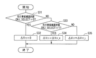
先行車候補Y方向相対速度選択部53では、入力される先行車候補選択値OBJ_SELECT、左先行車候補Y方向相対速度ΔV1Y_L及び右先行車候補Y方向相対速度ΔV1Y_Rに基づいて先行車候補Y方向相対速度ΔV1Yを算出する。図11は、その算出処理の処理手順を示す。
【0065】
先ずステップS31において、先行車候補Y方向相対速度選択部53は、先行車候補選択値OBJ_SELECTが0か否か、すなわち先行車候補がなしか否かを判定する。ここで、先行車候補Y方向相対速度選択部53は、先行車候補選択値OBJ_SELECTが0の場合、ステップS32に進み、先行車候補選択値OBJ_SELECTが0でない場合、ステップS33に進む。
【0066】
ステップS32では、先行車候補Y方向相対速度選択部53は、先行車候補Y方向相対速度ΔV1Yを0にして、当該処理を終了する。
ステップS33では、先行車候補Y方向相対速度選択部53は、先行車候補選択値OBJ_SELECTが1か否か、すなわち自車線の右側車線を走行している先行車候補が最終的な先行車候補になったか否かを判定する。ここで、先行車候補Y方向相対速度選択部53は、先行車候補選択値OBJ_SELECTが1の場合、ステップS34に進み、先行車候補選択値OBJ_SELECTが1でない場合、すなわち先行車候補選択値OBJ_SELECTが2の場合、ステップS35に進む。
【0067】
ステップS34では、先行車候補Y方向相対速度選択部53は、先行車候補Y方向相対速度ΔV1Yを右車線先行車候補Y方向相対速度ΔV1Y_Rにして、当該処理を終了する。
ステップS35では、先行車候補Y方向相対速度選択部53は、先行車候補Y方向相対速度ΔV1Yを左車線先行車候補Y方向相対速度ΔV1Y_Lにして、当該処理を終了する。
【0068】
先行車候補Y方向相対速度選択部53は、以上のような処理手順により、先行車候補Y方向相対速度ΔV1Yを算出する。そして、先行車候補Y方向相対速度選択部53は、算出した先行車候補Y方向相対速度ΔV1Yを変速比指令値Y方向補正マップ部56に出力する。
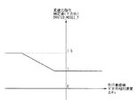
変速比指令値Y方向補正マップ部56は、入力された先行車候補Y方向相対速度ΔV1Yに基づいて、Y方向についての変速比指令値補正値(以下、変速比指令値Y方向補正値という。)DRATIO_HOSEI_Yを決定する。変速比指令値Y方向補正マップ部56は、マップをもとに、先行車候補Y方向相対速度ΔV1Yに基づいて変速比指令値Y方向補正値DRATIO_HOSEI_Yを決定しており、図12は、そのマップの例を示す。
【0069】
図12に示すマップでは、先行車候補Y方向相対速度ΔV1Yが0近傍又はそれ以上の場合、すなわちY方向(自車両の走行方向)において自車速と先行車候補速度とが同等か又は先行車候補速度の方が大きい場合、変速比指令値Y方向補正値DRATIO_HOSEI_Yを1にする。ここで、Y方向において自車速と先行車候補速度とが同等か又は先行車候補速度の方が大きい場合とは、Y方向において自車両と先行車候補との近づく程度が小さいか、自車両と走行車候補とが離れていく場合である。
【0070】
また、先行車候補Y方向相対速度ΔV1Yが前記0近傍よりも小さい場合、すなわち先行車候補速度よりも自車速の方が大きい場合、先行車候補Y方向相対速度ΔV1Yが負の方向に大きくなるにしたがい、変速比指令値X方向補正値DRATIO_HOSEI_Yを1から増加させ、さらに、先行車候補Y方向相対速度ΔV1Yがある負の値になった以降では、変速比指令値Y方向補正値DRATIO_HOSEI_Yを1.5にする。
【0071】
変速比指令値Y方向補正マップ部56はこのように先行車候補Y方向相対速度ΔV1Yに基づいて変速比指令値Y方向補正値DRATIO_HOSEI_Yを得ており、この変速比指令値Y方向補正値DRATIO_HOSEI_Yは変速比補正演算部60に出力される。
変速比補正演算部60は、入力された補正前変速比指令値DRATIO0、変速比指令値X方向補正値DRATIO_HOSEL_X、変速比指令値Y方向補正値DRATIO_HOSEI_Y及び変速比指令値X方向変化量補正値DRATIO_HOSEI_dXに基づいて変速比指令値DRATIOを算出する。図13は、その算出処理を実現する変速比補正演算部60の構成を示す。変速比補正演算部60は、図13に示すように、乗算器61,62,63、上下限リミッタ処理部64及びフィルタ処理部65を備えている。
【0072】
乗算器61,62,63にはそれぞれ、補正前変速比指令値DRATIO0、変速比指令値X方向補正値DRATIO_HOSEL_X、変速比指令値Y方向補正値DRATIO_HOSEI_Y及び変速比指令値X方向変化量補正値DRATIO_HOSEI_dXが入力されており、これにより、乗算器61から入力された補正前変速比指令値DRATIO0に、それら各補正値が乗算されて、変速比指令値リミッタ処理前値DRATIO1とされる。
【0073】
上下限リミッタ処理部64では、変速比指令値リミッタ処理前値DRATIO1に対して上下限リミッタ処理を施し、変速比指令値フィルタ処理前値DRATIO2を得る。具体的には、上下限リミッタ処理部64では、変速比指令値リミッタ処理前値DRATIO1が変速比指令値上限値DRATIO_MAXより大きい場合、変速比指令値フィルタ処理前値DRATIO2を変速比指令値上限値DRATIO_MAXとする(DRATIO2=DRATIO_MAX)。また、変速比指令値リミッタ処理前値DRATIO1が変速比指令値下限値DRATIO_MINより小さい場合、変速比指令値フィルタ処理前値DRATIO2を変速比指令値下限値DRATIO_MINとする(DRATIO2=DRATIO_MIN)。また、変速比指令値フィルタ処理前値DRATIO2が変速比指令値下限値DRATIO_MINと変速比指令値上限値DRATIO_MAXとの間の値の場合、変速比指令値フィルタ処理前値DRATIO2をそのままの値に維持する。
【0074】
フィルタ処理部65では、変速比指令値フィルタ処理前値DRATIO2をフィルタ処理を施して、最終的な変速比指令値DRATIOを得る。ここで、図13に示すフィルタ処理部65のτDRATIOは時定数であり、フィルタ処理部65は、この時定数τDRATIOのローパスフィルタ処理を施すことで、速度比指令値の急変を防止した変速比指令値DRATIOを得る。
【0075】
以上のように変速比指令値補正部50は構成されており、各種情報、すなわち補正前変速比指令値DRATIO0、左車線先行車候補認識フラグFL、右車線先行車候補認識フラグFR、左車線先行車候補車間距離L1A_L、右車線先行車候補車間距離L1A_R、先行車候補選択値OBJ_SELECT、左車線先行車候補X方向相対速度ΔV1X_L、右車線先行車候補X方向相対速度ΔV1X_R、左先行車候補Y方向相対速度ΔV1Y_L及び右先行車候補Y方向相対速度ΔV1Y_Rに基づいて最終的な変速比指令値DRATIOを得ている。そして、駆動トルク指令値分配部40は、この変速比指令値補正部50が得た変速比指令値DRATIOを無段変速機コントローラ21に出力する。無段変速機コントローラ21では、この変速比指令値DRATIOに基づいて変速機の変速比を制御をする。ここで、無段変速機コントローラ21は、変速比指令値DRATIOが大きいほど、変速比を低速側に変更する。
【0076】
次に本発明を適用したことで特徴となる変速比指令値補正部50の一連の処理動作を説明する。
例えば、先行車追従制御装置30は、電源投入後、後述するセットスイッチ11がオンされると制御を開始し、車速指令値VCOMに自車両VAが一致するように、無段変速機コントローラ21及びエンジン出力コントローラ22に指令値を出力するように動作する。
【0077】
このとき、特に、先行車候補選択部51は、左車線先行車候補認識フラグFL、右車線先行車候補認識フラグFR、左車線先行車候補車間距離L1A_L及び右車線先行車候補車間距離L1A_Rに基づいて先行車候補選択値OBJ_SELECTを設定する(図6参照)。具体的には、先行車候補がなしの場合、先行車候補選択値OBJ_SELECTを"0"に設定し(OBJ_SELECT=0)、右車線を走行している先行車候補が最終的な先行車候補になる場合、先行車候補選択値OBJ_SELECTを"1"に設定し(OBJ_SELECT=1)、左車線を走行している先行車候補が最終的な先行車候補になる場合、先行車候補選択値OBJ_SELECTを"2"に設定する(OBJ_SELECT=2)。そして、先行車候補選択部51は、この先行車候補選択値OBJ_SELECTを、先行車候補X方向相対速度選択部52、先行車候補Y方向相対速度選択部53及び先行車候補X方向相対速度変化量演算部55に出力する。
【0078】
先行車候補X方向相対速度選択部52は、先行車候補選択値OBJ_SELECT、左車線先行車候補X方向相対速度ΔV1X_L及び右車線先行車候補X方向相対速度ΔV1X_Rに基づいて先行車候補X方向相対速度ΔV1Xを算出する(図7参照)。具体的には、先行車候補X方向相対速度選択部52は、先行車候補がなしの場合(OBJ_SELECT=0)、先行車候補X方向相対速度ΔV1Xを0にし、右側車線を走行している先行車が先行車候補の場合(OBJ_SELECT=1)、先行車候補X方向相対速度ΔV1Xを右車線先行車候補X方向相対速度ΔV1X_Rにし、左側車線を走行している先行車が先行車候補の場合(OBJ_SELECT=2)、先行車候補X方向相対速度ΔV1Xを左車線先行車候補X方向相対速度ΔV1X_Lにする。これにより、先行車候補X方向相対速度選択部52は、先行車候補X方向相対速度ΔV1Xを先行車候補(最終的に選択した先行車候補)に対応する値に設定している。そして、先行車候補X方向相対速度選択部52は、この先行車候補X方向相対速度ΔV1Xを変速比指令値X方向補正マップ部54及び先行車候補X方向相対速度変化量演算部55に出力する。
【0079】
また、先行車候補X方向相対速度変化量演算部55は、先行車候補選択値OBJ_SELECT及び先行車候補X方向相対速度ΔV1Xに基づいて先行車候補X方向相対速度変化量dΔV1Xを算出する(図9参照)。具体的には、先行車候補X方向相対速度変化量演算部55は、先行車候補の変更がない場合(OBJ_SELECT(今回値)=OBJ_SELECT(前回値))、(12)式により先行車候補X方向相対速度変化量dΔV1Xを更新していく。一方、先行車候補X方向相対速度変化量演算部55は、先行車候補が変更している場合、最初から先行車候補X方向相対速度変化量dΔV1Xの更新をやり直す。そして、先行車候補X方向相対速度変化量演算部55は、この先行車候補X方向相対速度変化量dΔV1Xを変速比指令値X方向変化量補正マップ部57に出力する。
【0080】
また、先行車候補Y方向相対速度選択部53は、先行車候補選択値OBJ_SELECT、左車線先行車候補Y方向相対速度ΔV1Y_L及び右車線先行車候補Y方向相対速度ΔV1Y_Rに基づいて先行車候補Y方向相対速度ΔV1Yを算出する(図11参照)。具体的には、先行車候補Y方向相対速度選択部53は、先行車候補がなしの場合(OBJ_SELECT=0)、先行車候補Y方向相対速度ΔV1Yを0にし、右側車線を走行している先行車が先行車候補の場合(OBJ_SELECT=1)、先行車候補Y方向相対速度ΔV1Yを右車線先行車候補Y方向相対速度ΔV1Y_Rにし、左側車線を走行している先行車が先行車候補の場合(OBJ_SELECT=2)、先行車候補Y方向相対速度ΔV1Yを左車線先行車候補Y方向相対速度ΔV1Y_Lにする。これにより、先行車候補Y方向相対速度選択部53は、先行車候補Y方向相対速度ΔV1Yを先行車候補(最終的に選択した先行車候補)に対応する値に設定している。そして、先行車候補Y方向相対速度選択部53は、この先行車候補Y方向相対速度ΔV1Yを変速比指令値Y方向補正マップ部56に出力する。
【0081】
以上の処理により、先行車候補X方向相対速度選択部52、先行車候補X方向相対速度変化量演算部55及び先行車候補Y方向相対速度選択部53から変速比指令値X方向補正マップ部54、変速比指令値X方向変化量補正マップ部57及び変速比指令値Y方向補正マップ部56それぞれに補正値を得るための値が出力される。
【0082】
これにより、変速比指令値X方向補正マップ部54では、先行車候補X方向相対速度ΔV1Xに基づいて変速比指令値X方向補正値DRATIO_HOSEI_Xを決定する(図8参照)。また、変速比指令値X方向変化量補正マップ部57では、先行車候補X方向相対速度変化量dΔV1Xに基づいて変速比指令値X方向変化量補正値DRATIO_HOSEI_dXを決定する(図10参照)。さらに、変速比指令値Y方向補正マップ部56では、先行車候補Y方向相対速度ΔV1Yに基づいて変速比指令値Y方向補正値DRATIO_HOSEI_Yを決定する(図12参照)。
【0083】
そして、変速比補正演算部60では、変速比指令値X方向補正値DRATIO_HOSEL_X、変速比指令値Y方向補正値DRATIO_HOSEI_Y及び変速比指令値X方向変化量補正値DRATIO_HOSEI_dXに基づいて補正前変速比指令値DRATIO0を補正し、変速比指令値DRATIOを算出する(図13参照)。具体的には、補正前変速比指令値DRATIO0に、変速比指令値X方向補正値DRATIO_HOSEL_X、変速比指令値Y方向補正値DRATIO_HOSEI_Y及び変速比指令値X方向変化量補正値DRATIO_HOSEI_dXの各値を乗算し、さらに上下限リミッタ処理及びローパスフィルタ処理を施し、最終的に変速比指令値DRATIOを得ている。そして、無段変速機コントローラ21は、この変速比指令値DRATIOに基づいて変速機の変速比を制御する。
【0084】
ここで、変速比指令値X方向補正マップ部54では、X方向において自車速と先行車候補速度とが同等か又は先行車候補速度の方が大きい場合、変速比指令値X方向補正値DRATIO_HOSEI_Xを1にしている。一方で、変速比指令値X方向補正マップ部54では、X方向において先行車候補速度よりも自車速の方が大きい場合、先行車候補X方向相対速度ΔV1Xが負の方向に大きくなるにしたがい、変速比指令値X方向補正値DRATIO_HOSEI_Xを1から増加させ、さらに、先行車候補X方向相対速度ΔV1Xがある負の値になった以降では、変速比指令値X方向補正値DRATIO_HOSEI_Xを1.5にしている。一方、前述したように、補正前変速比指令値DRATIO0に変速比指令値X方向補正値DRATIO_HOSEI_Xを乗算して変速比指令値DRATIOを得ており、このようなことから、X方向において先行車候補速度よりも自車速の方が一定以上大きくなった場合、変速比指令値DRATIOは、補正前変速比指令値DRATIO0が大きい方向に補正された値になる。これにより、変速比は、低速側に補正される。
【0085】
また、変速比指令値X方向変化量補正マップ部57では、先行車候補X方向相対速度ΔV1Xに変化がないか、又は大なる方向へ変化する場合、すなわち自車両が先行車から遠ざかろうとしている場合、変速比指令値X方向変化量補正値DRATIO_HOSEI_dXを1にしている。一方で、変速比指令値X方向変化量補正マップ部57では、先行車候補X方向相対速度ΔV1Xが小なる方向へ変化する場合、すなわち自車両が先行車に近づこうとしている場合、先行車候補X方向相対速度変化量dΔV1Xが負の方向に大きくなるにしたがい、変速比指令値X方向変化量補正値DRATIO_HOSEI_dXを1から増加させ、さらに、先行車候補X方向相対速度変化量dΔV1Xがある負の値になった以降では、変速比指令値X方向変化量補正値DRATIO_HOSEI_dXを1.5にしている。一方、前述したように、補正前変速比指令値DRATIO0に変速比指令値X方向変化量補正値DRATIO_HOSEI_dXを乗算して変速比指令値DRATIOを得ており、このようなことから、自車両がX方向の加速度を大きくして先行車に近づこうとしている場合(特にその近づく度合いが大きい場合)、変速比指令値DRATIOは、補正前変速比指令値DRATIO0が大きい方向に補正された値になる。これにより、変速比は、低速側に補正される。
【0086】
さらに、変速比指令値Y方向補正マップ部56では、Y方向において自車速と先行車候補速度とが同等か又は先行車候補速度の方が大きい場合、変速比指令値Y方向補正値DRATIO_HOSEI_Yを1にしている。一方で、変速比指令値Y方向補正マップ部56では、Y方向において先行車候補速度よりも自車速の方が大きい場合、先行車候補Y方向相対速度ΔV1Yが負の方向に大きくなるにしたがい、変速比指令値Y方向補正値DRATIO_HOSEI_Yを1から増加させ、さらに、先行車候補Y方向相対速度ΔV1Yがある負の値になった以降では、変速比指令値Y方向補正値DRATIO_HOSEI_Yを1.5にしている。一方、前述したように、補正前変速比指令値DRATIO0に変速比指令値Y方向補正値DRATIO_HOSEI_Yを乗算して変速比指令値DRATIOを得ており、このようなことから、Y方向において先行車候補速度よりも自車速の方が一定以上大きくなった場合、変速比指令値DRATIOは、補正前変速比指令値DRATIO0が大きい方向に補正された値になる。これにより、変速比は、低速側に補正される。
【0087】
次に効果を説明する。
前述したように、隣車線を走行している特定条件を満たす車両を先行車候補とし、自車両及びその先行車候補との間のY方向(走行方向)及びX方向(走行方向に直交する方向)の相対速度、及びX方向の相対速度の変化量に基づいて自車両と先行車との接近状態を検出し、その自車両と先行車候補との接近状態に基づいて、自車両の変速比を変更している。具体的には、Y方向(走行方向)或いはX方向(走行方向に直交する方向)の相対速度が負の方向に大なるほど、X方向の相対速度の変化量が負の方向に大なるほど、すなわち、自車両が先行車候補に近づいている場合、或いは先行車候補の後方に自車両が割り込もうとしている場合、変速比を減速側に予め変更している。すなわち、自車両の左右の車線を走行している車両の状況を検出し、先行車が自車線への割込みが予想される場合には、変速比を低速側に変更している。
【0088】
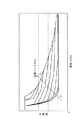
図14はその動作例を示す。図14中(A)は実車間距離変化を割り込み前後の時間変化として示し、図14中(B)は自車速変化を割り込み前後の時間変化として示し、図14中(C)は実変速比変化を割り込み前後の時間変化としている。そして、図中点線は本発明を適用して変速比を変更した結果を示し、図中実線は変速比の変更を行わない比較例の結果(従来の結果)を示す。また、時刻t1で先行車候補を発見し、時刻t2で割り込みが発生している。
【0089】
本発明の適用結果と比較例の結果とを比較してわかるように、本発明を適用することで、時刻t1で先行車候補を検出することで、変速比が大なる方向(減速側)へ予め変更している。これにより、時刻t2で割込みが発生しても速やかに減速することが可能となる。この結果、自車両と割り込み車両(先行車候補であった車両)に近づき過ぎてしまうことを防止することができる。
【0090】
以上、本発明の実施の形態について説明した。しかし、本発明は、前述の実施の形態として実現されることに限定されるものではない。
すなわち、前述の実施の形態では、車両が自車両の前方に割り込む場合を前提に説明しているが、自車両が他の車両が走行している車線に車線変更する場合にも、本発明の効果を得ることができる。この場合、自車両が車線変更するであろう車線を走行している車両が先行車候補になる。例えば、このような場合、例えばハンドルの操作状態、ウインカの操作状態、運転者の視線等の自車両側に属する情報に基づいて先行車候補を検出するようにしてもよい。
【0091】
また、前述の実施の形態では、変速比を変更するための補正値を具体的な値からなるマップ(図8、図10及び図12)に基づいて得る場合について説明したが、これに限定されるものではない。例えば、前記マップの値に限定されるものでもなく、さらに、マップ以外の手段、例えば数式により補正値を得るようにしてもよい。
【0092】
また、先行車追従制御装置により変速比が制御される変速機は、無段変速機でもよく、多段変速機でもよい。
また、前述の実施の形態では、本発明を先行車追従制御装置に適用した場合について説明したがこれに限定されるものではない。本発明は、変速制御装置に適用することができる。すなわち、本発明に係る変速制御装置は、将来先行車になるであろう先行車候補と自車両との接近状態に基づいて、自車両の変速比を変化させる。これにより、運転者が先行車を認識した場合、運転者がアクセルを戻すことで、迅速かつ十分な制動力を得ることができる。
【0093】
なお、前述の実施の形態の説明において、車間距離制御部32は、自車両と制御対象としての先行車との間の位置関係に基づいて目標車速を算出する目標車速算出手段を実現しており、車速指令値決定部33は、目標車速算出手段に合致するように自車速を制御する車速制御手段を実現しており、先行車候補選択部51は、制御対象になるであろう先行車候補を検出する先行車候補検出手段を実現しており、車間距離センサ16、先行車候補X方向相対速度選択部52、先行車候補Y方向相対度選択部53及び先行車候補X方向相対速度変化量演算部55は、先行車候補検出手段が検出した先行車候補と自車両との接近状態を検出する接近状態検出手段を実現しており、変速比指令値X方向補正マップ部54、変速比指令値Y方向補正マップ部56、変速比指令値X方向変化量補正マップ部57及び変速比補正演算部60は、接近状態検出手段が検出した前記接近状態に基づいて、自車両の変速比を変更する変速比変更手段を実現している。
【図面の簡単な説明】
【図1】本発明の実施の形態の走行車追従制御装置等の構成を示すブロック図である。
【図2】車間距離センサの所定角度αの範囲内で回動することで行う車間距離及び相対速度の検出の説明のために使用した図である。
【図3】前記走行車追従制御装置の駆動トルク指令値分配部の構成を示すブロック図である。
【図4】前記駆動トルク指令値分配部の変速比指令値設定部が有するマップであり、車速と変速比との関係を、駆動トルクをパラメータとしたマップを示す図である。
【図5】前記駆動トルク指令値分配部の変速比指令値補正部の構成を示すブロック図である。
【図6】前記変速比指令値補正部の先行車候補選択部による先行車候補選択値OBJ_SELECTの設定手順を示すフローチャートである。
【図7】前記変速比指令値補正部の先行車候補X方向相対速度選択部による先行車候補X方向相対速度ΔV1Xの算出手順を示すフローチャートである。
【図8】前記変速比指令値補正部の変速比指令値X方向補正マップ部が有するマップであり、先行車候補X方向相対速度ΔV1Xに基づいて変速比指令値X方向補正値DRATIO_HOSEI_Xを決定するためのマップを示す図である。
【図9】前記変速比指令値補正部の先行車候補X方向相対速度変化量演算部による先行車候補X方向相対速度変化量dΔV1Xの算出手順を示すフローチャートである。
【図10】前記変速比指令値補正部の変速比指令値X方向変化量補正マップ部の有するマップであり、先行車候補X方向相対速度変化量dΔV1Xに基づいて変速比指令値X方向変化量補正値DRATIO_HOSEI_dXを決定するためのマップを示す図である。
【図11】前記変速比指令値補正部の先行車候補Y方向相対速度選択部による先行車候補Y方向相対速度ΔV1Yの算出手順を示すフローチャートである。
【図12】前記変速比指令値補正部の変速比指令値Y方向補正マップ部が有するマップであり、先行車候補Y方向相対速度ΔV1Yに基づいて変速比指令値Y方向補正値DRATIO_HOSEI_Yを決定するためのマップを示す図である。
【図13】前記変速比指令値補正部の変速比補正演算部の構成を示すブロック図である。
【図14】本発明の効果の説明のために使用した図である。
【符号の説明】
11 セットスイッチ
12 アクラレートスイッチ
13 コーストスイッチ
14 車速センサ
15 車間時間設定部
16 車間距離センサ
17 エンジンセンサ
21 無段変速機コントローラ
22 エンジン出力コントローラ
30 先行車追従制御装置
31 速指令最大値設定部
32 車間距離制御部
33 車速指令値決定部
34 駆動トルク指令値算出部
35 実変速比算出部
40 駆動トルク指令値分配部
41 変速比指令値設定部
42 エンジントルク指令値算出部
50 変速比指令値補正部
51 先行車候補選択部
52 先行車候補X方向相対速度選択部
53 先行車候補Y方向相対速度選択部
54 変速比指令値X方向補正マップ部
55 先行車候補X方向相対速度変化量演算部
56 変速比指令値Y方向補正マップ部
57 変速比指令値X方向変化量補正マップ部
60 変速比補正演算部
61,62,63 乗算器
64 上下限フィルタ処理部
65 フィルタ処理部[0001]
TECHNICAL FIELD OF THE INVENTION
The present invention relates to a speed ratio control device that controls a speed ratio of a transmission, and a preceding vehicle follow-up control device that controls own vehicle speed based on a preceding vehicle.
[0002]
[Prior art]
Conventionally, as a preceding vehicle following control device, there is a technique described in
[0003]
Then, the preceding vehicle following control device calculates the following distance LYWhen the change of the following vehicle to be followed is detected based on the relative speed ΔV and the relative speed ΔV, the change speed V in the width direction of the preceding vehicle to be followed is changed.XIs measured, and the measured vehicle width direction change speed VXControl gain K of the preceding vehicle to be followed based onLCIs calculated. Then, the vehicle following travel control device changes the control gain K calculated in this manner.LCWith the normal control gain KLUIs set as a control gain, and the sensitivity of the inter-vehicle distance calculation processing is set to the vehicle width direction change speed VXTherefore, the following control at the time of interruption or lane change of the own vehicle is adjusted to an optimum state.
[0004]
[Patent Document 1]
JP-A-2002-87109
[0005]
[Problems to be solved by the invention]
However, in the case of a preceding vehicle following control device in which the own vehicle speed matches the target vehicle speed (the value calculated by the following distance control unit), the speed ratio is changed to a low speed side in response to a sudden interruption of the vehicle. It is conceivable to increase the engine brake. However, there are cases where a predetermined response time is required for the transmission ratio changing operation of the transmission.
The present invention has been made in view of the above-described circumstances, and has as its object to provide a speed ratio control device and a preceding vehicle follow-up control device that can quickly and sufficiently generate a braking force even when a vehicle is interrupted. And
[0006]
[Means for Solving the Problems]
In order to solve the above-mentioned problem, a gear ratio control device according to the first aspect of the present invention provides a gear ratio control system for a host vehicle based on an approaching state between the host vehicle and a preceding vehicle candidate which will become a preceding vehicle in the future. To change.
Further, the preceding vehicle following control device according to the invention described in
[0007]
A preceding vehicle following control device according to a seventh aspect of the present invention includes a target vehicle speed calculating means for calculating a target vehicle speed based on a positional relationship between the host vehicle and a preceding vehicle to be controlled, and the target vehicle speed calculating device. Vehicle speed control means for controlling the own vehicle speed so as to match the means, the preceding vehicle candidate detecting means which detects the preceding vehicle candidate to be controlled is detected by the preceding vehicle candidate detecting means, The approach state between the preceding vehicle candidate and the own vehicle is detected by the approach state detecting means, and the gear ratio of the own vehicle is changed by the gear ratio changing means based on the approach state detected by the approach state detecting means.
[0008]
【The invention's effect】
According to the speed ratio control device of the first aspect, the driver recognizes the preceding vehicle and returns the accelerator, whereby a quick and sufficient braking force can be obtained.
In addition, according to the preceding vehicle following control device of the sixth and seventh aspects, even when the preceding vehicle candidate is interrupted later or the like and becomes a control target of the traveling control, a quick and sufficient braking force can be obtained. Can be.
[0009]
BEST MODE FOR CARRYING OUT THE INVENTION
Hereinafter, embodiments of the present invention will be described in detail with reference to the drawings. This embodiment is a preceding vehicle follow-up control device. FIG. 1 is a block diagram showing a configuration relating to a preceding vehicle following control device and the preceding vehicle following control device. Hereinafter, the configuration and operation of each block shown in FIG. 1 will be described.
[0010]
The preceding vehicle following
[0011]
The preceding vehicle following
[0012]
The vehicle speed sensor 14 calculates the vehicle speed V based on the tire rotation speed and the like.AAnd the detected vehicle degree VAIs output to the preceding vehicle following
The inter-vehicle
[0013]
The
[0014]
Here, the values detected by the
The
[0015]
Further, the
[0016]
The
[0017]
Further, the
[0018]
The
As described above, the preceding vehicle following
[0019]
Here, the vehicle speed command maximum
[0020]
The vehicle speed command maximum
[0021]
The inter-vehicle
This inter-vehicle
[0022]
L*(T) = (VA(T) + ΔV (t)) × dT(T) ... (1)
Next, the following
The following
[0023]
(Equation 1)
Where ωnTIs the natural frequency of the target inter-vehicle distance response. In addition, a value arbitrarily set by the designerTIs a damping coefficient of a target inter-vehicle distance response, and in the equation (2) indicating a value arbitrarily set by a designer, the inter-vehicle distance command value L*Input (t), target inter-vehicle distance LTThe transfer function when (t) is output is expressed by the following equation (3).
LT(T) = ωnT 2・ E-LV · s・ L*(T) / (s2+ 2ζT・ ΩnT・ S + ωnT 2・ ・ ・ ・ ・ ・ (3)
Next, the inter-vehicle
[0025]
GV(s) '= 1 / (TV・ S + 1) (4)
Here, if the vehicle speed control unit corresponds to, for example, the description of JP-A-2001-328453, the vehicle speed command maximum
[0026]
The inter-vehicle
VC(T) = ωnT 2・ S (TV・ S + 1) ・ L*(T) / (s2+ 2ζT・ ΩnT・ S + ωnT 2・ ・ ・ ・ ・ ・ (5)
Also, from the state space representation using the above equation (2), VCWhen (t) is obtained, it becomes as shown in the following equation (6).
[0027]
(Equation 2)
Where TVIs a time constant used in the transfer characteristic of the vehicle speed control unit described above.
Then, the following
[0029]
V*(T) = VA(T) + ΔV (t) −VC(T)-{LT(T) -LA(T)} · fL− {ΔVT(T) −ΔV (t)} · fV ... (7)
Where the constant fL, FVIs a so-called feedback constant, and is a value calculated as disclosed in, for example, JP-A-2001-328453.
The inter-vehicle
[0030]
The vehicle speed command
[0031]
The drive torque command value calculation unit 34 calculates the input vehicle speed command value VCOMAnd own vehicle speed VADrive torque command value d based onFCIs calculated.
Here, the vehicle speed command value VCOM(T) as input, and own vehicle speed VAThe transfer characteristic GV (s) when (t) is the output can be expressed by the following equation (8).
GV(s) = 1 / (TV・ S + 1) ・ e(-Lv · s) ... (8)
Where TVIs the first-order lag time constant, and LVIs a dead time due to a delay in the power train system.
[0032]
The drive torque command value dFC(T) is the operation amount, and the vehicle speed VABy modeling (t) as a control amount, the behavior of the power train of the vehicle can be represented by a vehicle model to be controlled as a simplified linear model represented by the following equation (9).
VA(T) = 1 / (mV・ Rt ・ s) ・ e(-Lv · s)・ DFC(T) ... (9)
Here, Rt is the effective turning radius of the tire, and mVIs the vehicle mass. Thus, the drive torque command value dFC(T) as input, and own vehicle speed VAA vehicle model that outputs (t) has an integral characteristic because it has a form of 1 / s.
[0033]
The drive torque command value calculation unit 34 calculates the vehicle speed command value V input based on the above relationship.COMAnd own vehicle speed VAAnd the driving torque command value dFCGet. Then, the drive torque command value calculation unit 34 calculates the drive torque command value d.FCIs output to the drive torque command
As described above, the driving torque command
[0034]
The drive torque command
Hereinafter, the drive torque command
[0035]
The drive torque command
[0036]
TECOM= DFC/ (Gf・ RATIO) (11)
Where GfIs the final gear ratio.
The drive torque command
[0037]
The gear ratio command
[0038]
The speed ratio command
As shown in FIG. 5, the speed ratio command
[0039]
The preceding vehicle
[0040]
Specifically, the preceding vehicle
[0041]
Here, FIG. 6 shows a specific procedure of such setting processing of the preceding vehicle candidate selection value OBJ_SELECT of the preceding vehicle
First, in step S1, the preceding vehicle
[0042]
In step S2, the preceding vehicle
[0043]
Step S3 is a step in the case where the preceding vehicle in both the left and right lanes is recognized as a preceding vehicle candidate. In this step S3, the preceding vehicle
[0044]
In step S4, the preceding vehicle
In step S5, the preceding vehicle
[0045]
In step S1, the left lane preceding vehicle candidate recognition flag FLIn step S6, to which the process proceeds when the value is 0, the preceding vehicle
[0046]
In step S7, the preceding vehicle
In step S8, the preceding vehicle
[0047]
The preceding vehicle
[0048]
The preceding vehicle candidate X direction relative speed selection unit 52 includes, in addition to the preceding vehicle candidate selection value OBJ_SELECT, the left lane preceding vehicle candidate X direction relative speed ΔV.1X_LAnd right lane preceding vehicle candidate X direction relative speed ΔV1X_RIs entered. Based on these input values, the preceding vehicle candidate X-direction relative speed selection unit 52 calculates the preceding vehicle candidate X-direction relative speed ΔV1XIs calculated. FIG. 7 shows a processing procedure of the calculation processing.
[0049]
First, in step S11, the preceding vehicle candidate X direction relative speed selection unit 52 determines whether or not the preceding vehicle candidate selection value OBJ_SELECT is 0, that is, whether there is no preceding vehicle candidate. Here, the preceding vehicle candidate X direction relative speed selection unit 52 proceeds to step S12 when the preceding vehicle candidate selection value OBJ_SELECT is 0, and proceeds to step S13 when the preceding vehicle candidate selection value OBJ_SELECT is not 0.
[0050]
In step S12, the preceding vehicle candidate X direction relative speed selection unit 52 outputs the preceding vehicle candidate X direction relative speed ΔV.1XIs set to 0, and the process ends.
In step S13, the preceding vehicle candidate X direction relative speed selection unit 52 determines whether or not the preceding vehicle candidate selection value OBJ_SELECT is 1, that is, the preceding vehicle candidate traveling in the right lane of the own lane is the final preceding vehicle candidate. It is determined whether or not it has become. Here, if the preceding vehicle candidate selection value OBJ_SELECT is 1, the process proceeds to step S14, and if the preceding vehicle candidate selection value OBJ_SELECT is not 1, that is, if the preceding vehicle candidate selection value OBJ_SELECT is In the case of 2, the process proceeds to step S15.
[0051]
In step S14, the preceding vehicle candidate X direction relative speed selection unit 52 outputs the preceding vehicle candidate X direction relative speed ΔV.1XTo the right lane preceding vehicle candidate X direction relative speed ΔV1X_RThen, the process ends.
In step S15, the preceding vehicle candidate X direction relative speed selection unit 52 outputs the preceding vehicle candidate X direction relative speed ΔV.1XIs the left lane preceding vehicle candidate X direction relative speed ΔV1X_LThen, the process ends.
[0052]
The preceding vehicle candidate X direction relative speed selection unit 52 performs the preceding vehicle candidate X direction relative speed ΔV1XIs calculated. Then, the preceding vehicle candidate X direction relative speed selection unit 52 calculates the calculated preceding vehicle candidate X direction relative speed ΔV.1XIs output to the gear ratio command value X-direction
[0053]
The gear ratio command value X-direction
[0054]
In the map shown in FIG. 8, the preceding vehicle candidate X direction relative speed ΔV1XIs greater than or equal to 0, that is, if the own vehicle speed and the preceding vehicle candidate speed are equal to each other or the preceding vehicle candidate speed is higher in the X direction (the direction orthogonal to the traveling direction of the own vehicle), the gear ratio command value Set the X-direction correction value DRATIO_HOSEI_X to 1. Here, the case where the own vehicle speed and the preceding vehicle candidate speed are equal in the X direction or the case where the preceding vehicle candidate speed is higher is that the degree of approach between the own vehicle and the preceding vehicle candidate in the X direction is small, This is a case where the traveling vehicle candidate is moving away.
[0055]
The preceding vehicle candidate X direction relative speed ΔV1XIs smaller than the vicinity of 0, that is, when the own vehicle speed is higher than the preceding vehicle candidate speed and the degree to which the own vehicle approaches the preceding vehicle candidate is larger, the preceding vehicle candidate X direction relative speed ΔV1XIncreases in the negative direction, the gear ratio command value X-direction correction value DRATIO_HOSEI_X is increased from 1, and the preceding vehicle candidate X-direction relative speed ΔV1XAfter a certain negative value, the speed ratio command value X-direction correction value DRATIO_HOSEI_X is set to 1.5.
[0056]
The gear ratio command value X-direction
The preceding vehicle candidate X direction relative speed change
[0057]
First, in step S21, the preceding vehicle candidate X direction relative speed change
[0058]
In step S22, the preceding vehicle candidate X-direction relative speed change
dΔV1X= ΔV1X-ΔV1XPrevious value (12)
The preceding vehicle candidate X direction relative speed change amount dΔV1XIs a value indicating the amount of change in the position in the X direction between the own vehicle and the preceding vehicle candidate.
[0059]
The preceding vehicle candidate X direction relative speed change
In step S23, the preceding vehicle candidate X direction relative speed change
[0060]
In step S24, the preceding vehicle candidate X direction relative speed change
Subsequently, in step S25, the preceding vehicle candidate X direction relative speed change
[0061]
If the preceding vehicle candidate X-direction relative speed change
[0062]
In the gear ratio command value X-direction change amount
In the map shown in FIG. 10, the preceding vehicle candidate X direction relative speed change amount dΔV1XIs near zero or more, that is, the preceding vehicle candidate X direction relative speed ΔV1XIf the vehicle speed does not change or changes in a larger direction (when the host vehicle is accelerating), the gear ratio command value X-direction change amount correction value DRATIO_HOSEI_dX is set to 1. In addition, the preceding vehicle candidate X direction relative speed change amount dΔV1XIs smaller than the vicinity of 0, that is, the preceding vehicle candidate X direction relative speed ΔV1XChanges in the direction in which the vehicle speed decreases, the preceding vehicle candidate X direction relative speed change amount dΔV1XIncreases in the negative direction, the gear ratio command value X-direction change amount correction value DRATIO_HOSEI_dX is increased from 1, and the preceding vehicle candidate X-direction relative speed change amount dΔV is further increased.1XAfter a certain negative value, the speed ratio command value X-direction change amount correction value DRATIO_HOSEI_dX is set to 1.5.
[0063]
Here, the preceding vehicle candidate X direction relative speed change amount dΔV1XA positive value of indicates that the own vehicle is moving away from the preceding vehicle. For example, this is a case where the deceleration of the own vehicle in the X direction becomes large. In addition, the preceding vehicle candidate X direction relative speed change amount dΔV1XIs a case where the own vehicle is approaching the preceding vehicle. For example, this is a case where the acceleration of the own vehicle in the X direction increases.
[0064]
The speed ratio command value X-direction
In the preceding vehicle candidate Y direction relative
[0065]
First, in step S31, the preceding vehicle candidate Y direction relative
[0066]
In step S32, the preceding vehicle candidate Y direction
In step S33, the preceding vehicle candidate Y direction relative
[0067]
In step S34, the preceding vehicle candidate Y direction
In step S35, the preceding vehicle candidate Y direction relative
[0068]
The preceding vehicle candidate Y direction relative
The speed ratio command value Y direction
[0069]
In the map shown in FIG. 12, the preceding vehicle candidate Y direction relative speed ΔV1YIs greater than or equal to 0, that is, if the own vehicle speed is equal to the preceding vehicle candidate speed or the preceding vehicle candidate speed is higher in the Y direction (the running direction of the own vehicle), the gear ratio command value Y direction correction value Set DRATIO_HOSEI_Y to 1. Here, the case where the own vehicle speed and the preceding vehicle candidate speed are equal in the Y direction or the case where the preceding vehicle candidate speed is higher is that the degree of approach of the own vehicle and the preceding vehicle candidate in the Y direction is small, This is a case where the traveling vehicle candidate is moving away.
[0070]
In addition, the preceding vehicle candidate Y direction relative speed ΔV1YIs smaller than the vicinity of 0, that is, when the own vehicle speed is higher than the preceding vehicle candidate speed, the preceding vehicle candidate Y direction relative speed ΔV1YIncreases in the negative direction, the speed ratio command value X-direction correction value DRATIO_HOSEI_Y is increased from 1, and the preceding vehicle candidate Y-direction relative speed ΔV1YAfter a certain negative value, the speed ratio command value Y-direction correction value DRATIO_HOSEI_Y is set to 1.5.
[0071]
The speed ratio command value Y direction
The gear ratio
[0072]
Each of the
[0073]
In the upper / lower
[0074]
In the filter processing unit 65, the gear ratio command value pre-filter value DRATIO2To obtain a final speed ratio command value DRATIO. Here, τ of the filter processing unit 65 shown in FIG.DRATIOIs a time constant, and the filtering unit 65 calculates the time constant τDRATIOBy performing the low-pass filter processing described above, a speed ratio command value DRATIO that prevents a sudden change in the speed ratio command value is obtained.
[0075]
The speed ratio command
[0076]
Next, a series of processing operations of the gear ratio command
For example, the preceding vehicle following
[0077]
At this time, in particular, the preceding vehicle
[0078]
The preceding vehicle candidate X direction relative speed selection unit 52 calculates the preceding vehicle candidate selection value OBJ_SELECT, the left lane preceding vehicle candidate X direction relative speed ΔV.1X_LAnd right lane preceding vehicle candidate X direction relative speed ΔV1X_RBased on the preceding vehicle candidate X direction relative speed ΔV1XIs calculated (see FIG. 7). Specifically, when there is no preceding vehicle candidate (OBJ_SELECT = 0), the preceding vehicle candidate X direction relative speed selection unit 52 determines that the preceding vehicle candidate X direction relative speed ΔV1XIs set to 0, and if the preceding vehicle traveling in the right lane is a candidate for a preceding vehicle (OBJ_SELECT = 1), the relative speed ΔV in the X direction of the preceding vehicle candidate1XTo the right lane preceding vehicle candidate X direction relative speed ΔV1X_RIf the preceding vehicle traveling in the left lane is a candidate for a preceding vehicle (OBJ_SELECT = 2), the relative speed ΔV in the X direction of the preceding vehicle candidate1XIs the left lane preceding vehicle candidate X direction relative speed ΔV1X_LTo Thereby, the preceding vehicle candidate X direction relative speed selection unit 52 outputs the preceding vehicle candidate X direction relative speed ΔV.1XIs set to a value corresponding to the preceding vehicle candidate (finally selected preceding vehicle candidate). Then, the preceding vehicle candidate X direction relative speed selection unit 52 calculates the preceding vehicle candidate X direction relative speed ΔV.1XIs output to the gear ratio command value X-direction
[0079]
The preceding vehicle candidate X-direction relative speed change
[0080]
Further, the preceding vehicle candidate Y direction relative
[0081]
By the above processing, the preceding vehicle candidate X-direction relative speed selector 52, the preceding vehicle candidate X-direction relative speed
[0082]
As a result, in the gear ratio command value X-direction
[0083]
Then, in the gear ratio
[0084]
Here, in the gear ratio command value X direction
[0085]
In the gear ratio command value X direction change amount
[0086]
Further, the speed ratio command value Y direction
[0087]
Next, the effects will be described.
As described above, a vehicle traveling in the adjacent lane and satisfying specific conditions is defined as a preceding vehicle candidate, and the Y direction (running direction) and the X direction (direction orthogonal to the running direction) between the own vehicle and the preceding vehicle candidate are set. ), The approach state between the host vehicle and the preceding vehicle is detected based on the relative speed in the X direction and the change amount of the relative speed in the X direction. Has changed. Specifically, as the relative speed in the Y direction (running direction) or X direction (direction orthogonal to the running direction) increases in the negative direction, and as the amount of change in the relative speed in the X direction increases in the negative direction, When the own vehicle is approaching the preceding vehicle candidate, or when the own vehicle is about to interrupt behind the preceding vehicle candidate, the gear ratio is changed to the reduction side in advance. That is, the state of the vehicle traveling in the left and right lanes of the own vehicle is detected, and when the preceding vehicle is expected to interrupt the own lane, the gear ratio is changed to the lower speed side.
[0088]
FIG. 14 shows an example of the operation. 14A shows a change in the actual inter-vehicle distance as a time change before and after the interruption, FIG. 14B shows a change in the own vehicle speed as a time change before and after the interruption, and FIG. 14C shows a change in the actual gear ratio. Is the time change before and after the interruption. The dotted line in the figure shows the result of changing the gear ratio by applying the present invention, and the solid line in the figure shows the result (conventional result) of the comparative example in which the gear ratio is not changed. In addition, a preceding vehicle candidate is found at time t1, and an interrupt occurs at time t2.
[0089]
As can be seen by comparing the result of applying the present invention with the result of the comparative example, by applying the present invention, a candidate for a preceding vehicle is detected at time t1, thereby increasing the gear ratio (toward the deceleration side). It has been changed in advance. This makes it possible to quickly decelerate even if an interrupt occurs at time t2. As a result, it is possible to prevent the host vehicle and the interrupting vehicle (vehicles that were candidate preceding vehicles) from being too close to each other.
[0090]
The embodiment of the invention has been described. However, the present invention is not limited to being realized as the above-described embodiment.
That is, in the above-described embodiment, the description has been made on the assumption that the vehicle interrupts in front of the own vehicle. However, the present invention is also applicable to the case where the own vehicle changes lanes to the lane where another vehicle is traveling. The effect can be obtained. In this case, a vehicle running on a lane in which the own vehicle will change lanes is a candidate for a preceding vehicle. For example, in such a case, the preceding vehicle candidate may be detected based on information belonging to the host vehicle such as the operating state of the steering wheel, the operating state of the turn signal, and the driver's line of sight.
[0091]
Further, in the above-described embodiment, the case where the correction value for changing the gear ratio is obtained based on the map (FIGS. 8, 10, and 12) made up of specific values has been described. Not something. For example, the correction value is not limited to the value of the map, and the correction value may be obtained by means other than the map, for example, a mathematical expression.
[0092]
The transmission whose speed ratio is controlled by the preceding vehicle following control device may be a continuously variable transmission or a multi-stage transmission.
Further, in the above-described embodiment, the case where the present invention is applied to the preceding vehicle following control device has been described, but the present invention is not limited to this. The present invention can be applied to a shift control device. That is, the transmission control device according to the present invention changes the transmission ratio of the host vehicle based on the approaching state between the host vehicle and the preceding vehicle candidate that will become the preceding vehicle in the future. Thus, when the driver recognizes the preceding vehicle, the driver can return the accelerator to obtain a quick and sufficient braking force.
[0093]
In the description of the above-described embodiment, the following
[Brief description of the drawings]
FIG. 1 is a block diagram illustrating a configuration of a traveling vehicle tracking control device and the like according to an embodiment of the present invention.
FIG. 2 is a diagram used to explain detection of an inter-vehicle distance and a relative speed performed by rotating the inter-vehicle distance sensor within a range of a predetermined angle α.
FIG. 3 is a block diagram showing a configuration of a drive torque command value distribution unit of the traveling vehicle following control device.
FIG. 4 is a map included in a gear ratio command value setting unit of the drive torque command value distribution unit, and is a diagram illustrating a map in which a relationship between a vehicle speed and a gear ratio is set using a drive torque as a parameter.
FIG. 5 is a block diagram showing a configuration of a gear ratio command value correction unit of the drive torque command value distribution unit.
FIG. 6 is a flowchart showing a procedure for setting a preceding vehicle candidate selection value OBJ_SELECT by a preceding vehicle candidate selection unit of the speed ratio command value correction unit.
FIG. 7 shows a preceding vehicle candidate X direction relative speed ΔV by a preceding vehicle candidate X direction relative speed selection unit of the speed ratio command value correction unit.1X6 is a flowchart showing a calculation procedure of the calculation.
FIG. 8 is a map included in a gear ratio command value X direction correction map unit of the gear ratio command value correction unit, and is a relative speed ΔV in a preceding vehicle candidate X direction.1XFIG. 9 is a diagram showing a map for determining a gear ratio command value X-direction correction value DRATIO_HOSEI_X based on the map.
FIG. 9 is a diagram showing a relative speed change dΔV of a preceding vehicle candidate in the X direction by a preceding vehicle candidate X direction relative speed change calculating unit of the speed ratio command value correcting unit;1X6 is a flowchart showing a calculation procedure of the calculation.
FIG. 10 is a map included in a speed ratio command value X direction change amount correction map unit of the speed ratio command value correction unit, and is a relative speed change amount dΔV of a preceding vehicle candidate in the X direction.1XFIG. 9 is a diagram showing a map for determining a gear ratio command value X-direction change amount correction value DRATIO_HOSEI_dX based on the map.
FIG. 11 is a diagram showing a relative speed ΔV of a preceding vehicle candidate in a Y direction by a preceding vehicle candidate Y direction relative speed selecting unit of the speed ratio command value correcting unit;1Y6 is a flowchart showing a calculation procedure of the calculation.
FIG. 12 is a map included in a speed ratio command value Y direction correction map section of the speed ratio command value correction section, and is a relative speed ΔV in a preceding vehicle candidate Y direction.1YFIG. 9 is a diagram showing a map for determining a gear ratio command value Y-direction correction value DRATIO_HOSEI_Y based on the above.
FIG. 13 is a block diagram showing a configuration of a gear ratio correction calculating unit of the gear ratio command value correcting unit.
FIG. 14 is a diagram used for describing the effect of the present invention.
[Explanation of symbols]
11 Set switch
12 Accurate switch
13 Coast switch
14 Vehicle speed sensor
15 Inter-vehicle time setting section
16 Inter-vehicle distance sensor
17 Engine sensor
21 Continuously variable transmission controller
22 Engine output controller
30 Leading vehicle follow-up control device
31 Speed command maximum value setting section
32 Inter-vehicle distance control unit
33 Vehicle speed command value determination unit
34 Drive torque command value calculation unit
35 Actual gear ratio calculator
40 Drive torque command value distribution unit
41 Speed ratio command value setting section
42 Engine torque command value calculation unit
50 Gear ratio command value correction unit
51 preceding car candidate selection section
52 preceding vehicle candidate X direction relative speed selector
53 preceding vehicle candidate Y direction relative speed selector
54 Speed ratio command value X direction correction map section
55 preceding vehicle candidate X-direction relative speed change amount calculation unit
56 Speed ratio command value Y direction correction map section
57 Speed ratio command value X direction change amount correction map section
60 Gear ratio correction calculation unit
61,62,63 Multiplier
64 Upper / lower limit filter processing unit
65 Filter processing section
Claims (12)
前記目標車速算出手段に合致するように自車速を制御する車速制御手段と、
前記制御対象になるであろう先行車候補を検出する先行車候補検出手段と、
前記先行車候補検出手段が検出した先行車候補と自車両との接近状態を検出する接近状態検出手段と、
前記接近状態検出手段が検出した前記接近状態に基づいて、自車両の変速比を変更する変速比変更手段と、
を備えたことを特徴とする先行車追従制御装置。Target vehicle speed calculation means for calculating a target vehicle speed based on a positional relationship between the host vehicle and a preceding vehicle as a control target,
Vehicle speed control means for controlling the own vehicle speed to match the target vehicle speed calculation means,
Preceding vehicle candidate detecting means for detecting a preceding vehicle candidate that will be the control target;
Approaching state detecting means for detecting an approaching state between the preceding vehicle candidate and the own vehicle detected by the preceding vehicle candidate detecting means,
Speed ratio changing means for changing the speed ratio of the host vehicle based on the approach state detected by the approach state detection means,
A preceding vehicle following control device, comprising:
Priority Applications (1)
| Application Number | Priority Date | Filing Date | Title |
|---|---|---|---|
| JP2002369697A JP2004197891A (en) | 2002-12-20 | 2002-12-20 | Change gear ratio controller and leading car follow-up controller |
Applications Claiming Priority (1)
| Application Number | Priority Date | Filing Date | Title |
|---|---|---|---|
| JP2002369697A JP2004197891A (en) | 2002-12-20 | 2002-12-20 | Change gear ratio controller and leading car follow-up controller |
Publications (1)
| Publication Number | Publication Date |
|---|---|
| JP2004197891A true JP2004197891A (en) | 2004-07-15 |
Family
ID=32765849
Family Applications (1)
| Application Number | Title | Priority Date | Filing Date |
|---|---|---|---|
| JP2002369697A Pending JP2004197891A (en) | 2002-12-20 | 2002-12-20 | Change gear ratio controller and leading car follow-up controller |
Country Status (1)
| Country | Link |
|---|---|
| JP (1) | JP2004197891A (en) |
Cited By (4)
| Publication number | Priority date | Publication date | Assignee | Title |
|---|---|---|---|---|
| JP2006056485A (en) * | 2004-08-24 | 2006-03-02 | Daihatsu Motor Co Ltd | Method for selecting preceding vehicle, and device for selecting preceding vehicle |
| JP2014058229A (en) * | 2012-09-18 | 2014-04-03 | Daimler Ag | Driving support device |
| JP2015119538A (en) * | 2013-12-18 | 2015-06-25 | 旭化成株式会社 | Power control device and power supply system |
| JP2019001283A (en) * | 2017-06-14 | 2019-01-10 | 本田技研工業株式会社 | vehicle |
Citations (5)
| Publication number | Priority date | Publication date | Assignee | Title |
|---|---|---|---|---|
| JPH10338057A (en) * | 1997-06-10 | 1998-12-22 | Hitachi Ltd | Automatic travel controller and inter-vehicle distance warning device for automobile |
| JPH1148885A (en) * | 1997-08-05 | 1999-02-23 | Honda Motor Co Ltd | Distance measuring device for vehicle |
| JPH11342766A (en) * | 1998-06-04 | 1999-12-14 | Nissan Motor Co Ltd | Inter-vehicle distance control device |
| JP2001026228A (en) * | 1999-07-14 | 2001-01-30 | Denso Corp | Vehicle driving power control device and recording medium |
| JP2001235016A (en) * | 2000-02-22 | 2001-08-31 | Nissan Motor Co Ltd | Driving force control device for automobile |
-
2002
- 2002-12-20 JP JP2002369697A patent/JP2004197891A/en active Pending
Patent Citations (5)
| Publication number | Priority date | Publication date | Assignee | Title |
|---|---|---|---|---|
| JPH10338057A (en) * | 1997-06-10 | 1998-12-22 | Hitachi Ltd | Automatic travel controller and inter-vehicle distance warning device for automobile |
| JPH1148885A (en) * | 1997-08-05 | 1999-02-23 | Honda Motor Co Ltd | Distance measuring device for vehicle |
| JPH11342766A (en) * | 1998-06-04 | 1999-12-14 | Nissan Motor Co Ltd | Inter-vehicle distance control device |
| JP2001026228A (en) * | 1999-07-14 | 2001-01-30 | Denso Corp | Vehicle driving power control device and recording medium |
| JP2001235016A (en) * | 2000-02-22 | 2001-08-31 | Nissan Motor Co Ltd | Driving force control device for automobile |
Cited By (5)
| Publication number | Priority date | Publication date | Assignee | Title |
|---|---|---|---|---|
| JP2006056485A (en) * | 2004-08-24 | 2006-03-02 | Daihatsu Motor Co Ltd | Method for selecting preceding vehicle, and device for selecting preceding vehicle |
| JP4619064B2 (en) * | 2004-08-24 | 2011-01-26 | ダイハツ工業株式会社 | Prior vehicle selection method and preceding vehicle selection device |
| JP2014058229A (en) * | 2012-09-18 | 2014-04-03 | Daimler Ag | Driving support device |
| JP2015119538A (en) * | 2013-12-18 | 2015-06-25 | 旭化成株式会社 | Power control device and power supply system |
| JP2019001283A (en) * | 2017-06-14 | 2019-01-10 | 本田技研工業株式会社 | vehicle |
Similar Documents
| Publication | Publication Date | Title |
|---|---|---|
| US10065643B2 (en) | Vehicle travel control apparatus | |
| US10479363B2 (en) | Driving assist apparatus | |
| US10515552B2 (en) | Driving assist apparatus | |
| JP3775353B2 (en) | Preceding vehicle tracking control device | |
| US7561955B2 (en) | Preceding-vehicle following control system | |
| US7433772B2 (en) | Target speed control system for a vehicle | |
| EP1769962B1 (en) | Adaptive cruise control system for vehicle | |
| JP7151179B2 (en) | Lane change estimation device and lane change estimation method, vehicle control device and vehicle control method | |
| JP2004017847A (en) | Driving operation auxiliary device for vehicle | |
| JPH0776237A (en) | Traveling controller for automobile | |
| JP3788240B2 (en) | Vehicle tracking control device | |
| JP2010158924A (en) | Inter-vehicle distance controller | |
| CN113859240B (en) | Lane change assisting system and lane change method using the same | |
| JP2000355234A (en) | Preceding vehicle follow-up control device | |
| JP2017136897A (en) | Vehicle travel control device | |
| US11148666B2 (en) | Vehicle control apparatus | |
| JP2006224882A (en) | Vehicle deceleration control device | |
| JP2004197891A (en) | Change gear ratio controller and leading car follow-up controller | |
| JP2006036159A (en) | Vehicular traveling control device | |
| JP2010149859A (en) | Travel controller for vehicle | |
| JP2005297900A (en) | Vehicle speed control device | |
| JP2001027317A (en) | Automatic traveling controller and recording medium | |
| JPH0717298A (en) | Running control device for automobile | |
| JP3903913B2 (en) | VEHICLE DRIVE OPERATION ASSISTANCE DEVICE AND VEHICLE HAVING THE DEVICE | |
| JP2004161175A (en) | Travel speed control device |
Legal Events
| Date | Code | Title | Description |
|---|---|---|---|
| A621 | Written request for application examination |
Free format text: JAPANESE INTERMEDIATE CODE: A621 Effective date: 20051026 |
|
| A977 | Report on retrieval |
Free format text: JAPANESE INTERMEDIATE CODE: A971007 Effective date: 20070417 |
|
| A131 | Notification of reasons for refusal |
Free format text: JAPANESE INTERMEDIATE CODE: A131 Effective date: 20070424 |
|
| A521 | Written amendment |
Free format text: JAPANESE INTERMEDIATE CODE: A523 Effective date: 20070608 |
|
| A131 | Notification of reasons for refusal |
Free format text: JAPANESE INTERMEDIATE CODE: A131 Effective date: 20071113 |
|
| A02 | Decision of refusal |
Free format text: JAPANESE INTERMEDIATE CODE: A02 Effective date: 20080311 |