JP2004193045A - Fpc connector - Google Patents
Fpc connector Download PDFInfo
- Publication number
- JP2004193045A JP2004193045A JP2002362008A JP2002362008A JP2004193045A JP 2004193045 A JP2004193045 A JP 2004193045A JP 2002362008 A JP2002362008 A JP 2002362008A JP 2002362008 A JP2002362008 A JP 2002362008A JP 2004193045 A JP2004193045 A JP 2004193045A
- Authority
- JP
- Japan
- Prior art keywords
- fpc
- actuator
- shaft
- insulating housing
- terminal
- Prior art date
- Legal status (The legal status is an assumption and is not a legal conclusion. Google has not performed a legal analysis and makes no representation as to the accuracy of the status listed.)
- Granted
Links
Images


Classifications
-
- H—ELECTRICITY
- H01—ELECTRIC ELEMENTS
- H01R—ELECTRICALLY-CONDUCTIVE CONNECTIONS; STRUCTURAL ASSOCIATIONS OF A PLURALITY OF MUTUALLY-INSULATED ELECTRICAL CONNECTING ELEMENTS; COUPLING DEVICES; CURRENT COLLECTORS
- H01R12/00—Structural associations of a plurality of mutually-insulated electrical connecting elements, specially adapted for printed circuits, e.g. printed circuit boards [PCB], flat or ribbon cables, or like generally planar structures, e.g. terminal strips, terminal blocks; Coupling devices specially adapted for printed circuits, flat or ribbon cables, or like generally planar structures; Terminals specially adapted for contact with, or insertion into, printed circuits, flat or ribbon cables, or like generally planar structures
- H01R12/70—Coupling devices
- H01R12/82—Coupling devices connected with low or zero insertion force
- H01R12/85—Coupling devices connected with low or zero insertion force contact pressure producing means, contacts activated after insertion of printed circuits or like structures
- H01R12/88—Coupling devices connected with low or zero insertion force contact pressure producing means, contacts activated after insertion of printed circuits or like structures acting manually by rotating or pivoting connector housing parts
-
- H—ELECTRICITY
- H01—ELECTRIC ELEMENTS
- H01R—ELECTRICALLY-CONDUCTIVE CONNECTIONS; STRUCTURAL ASSOCIATIONS OF A PLURALITY OF MUTUALLY-INSULATED ELECTRICAL CONNECTING ELEMENTS; COUPLING DEVICES; CURRENT COLLECTORS
- H01R12/00—Structural associations of a plurality of mutually-insulated electrical connecting elements, specially adapted for printed circuits, e.g. printed circuit boards [PCB], flat or ribbon cables, or like generally planar structures, e.g. terminal strips, terminal blocks; Coupling devices specially adapted for printed circuits, flat or ribbon cables, or like generally planar structures; Terminals specially adapted for contact with, or insertion into, printed circuits, flat or ribbon cables, or like generally planar structures
- H01R12/70—Coupling devices
- H01R12/77—Coupling devices for flexible printed circuits, flat or ribbon cables or like structures
- H01R12/79—Coupling devices for flexible printed circuits, flat or ribbon cables or like structures connecting to rigid printed circuits or like structures
Abstract
Description
【0001】
【発明の属する技術分野】
この発明は、一般にFPC、FFCなどと呼ばれている平型柔軟ケーブル(この明細書においてもこれらを代表して単に「FPC」という。)を接続するためのFPC用コネクタに関する。
【0002】
【従来の技術】
従来この種のコネクタは、FPC挿入空間が設けられた絶縁ハウジングと、絶縁ハウジングに所定のピッチで並列して装着された複数の端子であって、それぞれに設けられたコンタクト片が前記FPC挿入空間に臨んでいる複数の端子と、FPC挿入空間にFPCを挿入可能とする第1の位置(開放位置)と、挿入されたFPCを端子のコンタクト片に向けて付勢する第2の位置(閉鎖位置)の間で回動可能に設けられたアクチュエータとを備えた構成とされていた。
【0003】
前記アクチュエータの第1の位置と第2の位置の間の回動は、実用新案登録第2580074号公報の図3、4、5に示され、特開2001−307829号公報の図2、3に示され、更には、特開2002−289283号公報の図1に示されているように、略固定された回動軸の回りで回動するようにしたものと、実用新案登録第3035692号公報の図1〜図10に順次示されているように、回動中心が移動しながら回動するようにしたものが知られている。
【0004】
回動可能に設けられたアクチュエータが第2の位置にある状態で、不用意に第1の位置の方向へ回動しないようにするために、特開2002−289283号公報の図5に表れているように、抑止翼55と、アクチュエータ(加圧部材)56の操作端側の両端に垂下片の形状で設けられている係合片(符号なし)を互いに係合するようにしている。アクチュエータが第2の位置にある状態は、絶縁ハウジングに挿入されたFPCと端子が電気的に接続した状態であり、この接続状態を安定に保つために、このような構成が採用されている。
【0005】
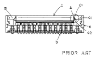
第2の位置にあるアクチュエータの位置を保持するための構造として、図19〜図21に示したような構造も知られている。図において、aが絶縁ハウジング、bが端子、cがアクチュエータである。アクチュエータcの両端面に断面が半円形の突部c1が設けられ、絶縁ハウジングaの両側壁a1の内面に形成された弧状の凹入係止部a2に係合するようにしている。
【0006】
アクチュエータの回動を制限する機構には、上記のほかに、実用新案登録第2580074号や特開2001−307829号公報で開示されているような、端子のコンタクト片の弾性反力を利用して、アクチュエータを閉鎖方向へ付勢する構成のものも知られている。実用新案登録第2580074号公報においては、明細書の段落[0019]〜[0021]、特に[0021]にこのことが説明されている。また、特開2001−307829号公報では、明細書の段落[0011]と[0013]にこのことが説明されている。
【0007】
【発明が解決しようとする課題】
アクチュエータが不用意に回動しないようにした前記の如くの構成のうち、前者のアクチュエータと絶縁ハウジングの間で係合構造を設けるようにしたものは、コネクタの高さや端子の並列している幅方向などで、コネクタ内にある一定の領域をさかなければならないので、コネクタの小型化を図る場合に困難に遭遇していた。
また、後者のコンタクト片の弾性反力を利用するようにしたものは、コネクタにFPCを接続した状態でなければコンタクト片の弾性反力が働かないものであった。このため、FPCを接続する前の、輸送や取付基板への実装の際に、外的衝撃でアクチュエータが不用意に回動してしまう(開いてしまう)という困難に遭遇していた。
【0008】
この発明は、このような事情を考慮して成されたもので、FPCの接続の有無に拘わらず、閉鎖位置(第2の位置)にあるアクチュエータが不用意に開放位置(第1の位置)の方向へ回動しないようにしたFPC用コネクタを提供することを目的としている。
【0009】
【課題を解決するための手段】
上記の目的はこの発明の、FPC挿入空間が設けられた絶縁ハウジングと、
絶縁ハウジングに所定のピッチで並列して装着された複数の端子であって、それぞれに設けられたコンタクト片が前記FPC挿入空間に臨んでいる複数の端子と、
FPC挿入空間にFPCを挿入可能とする第1の位置と、挿入されたFPCを端子のコンタクト片に向けて付勢する第2の位置の間で回動可能に設けられたアクチュエータとを備え、
前記アクチュエータが、回動軸方向で両端部に設けられた第1の軸と、この両端部の第1の軸の間に設けられた第2の軸を有しており、
アクチュエータを前記第2の位置から第1の位置に向けて回動する時、第2の軸の回動中心が第1の軸に対する第1支持部分から離れる方向へ移動するように、第1の軸の回動中心と第2の軸の回動中心がオフセットしていると共に、第2の軸が前記移動を弾性的に阻止する第2支持部分で軸支されていることを特徴とするFPC用コネクタ、によって達成される。
【0010】
【作用】
このように構成されるこの発明のFPC用コネクタによれば、アクチュエータに第1の軸と第2の軸がオフセット状態で設けられ、第2の軸が弾性反力を発揮できる第2支持部分で軸支されている構成としたので、コネクタにFPCが接続されている状態でも、接続されていない状態でも、第2の位置(閉鎖位置)にあるアクチュエータが第1の位置(開放位置)へ向けて不用意に回動しようとすると、第2の軸に第2支持部分から弾性反力が作用して回動を阻止する。
【0011】
前記アクチュエータの第1の軸は、請求項2のように、アクチュエータの後端側両端に突出して設け、絶縁ハウジング側に設けられた平坦な面でなる第1支持部分に載置して回動可能に軸支するのが好ましい。この場合、絶縁ハウジング側に設けられる第1支持部分は、絶縁ハウジングに一体として設けても良いが、請求項3のように、絶縁ハウジングに装着された支持金具の側縁で構成することで、支持部分を堅固にすることができる。このような支持金具には、請求項4のように、取付基板に半田付けが可能なネール部分を備えるようにすることで、部品点数の増加を抑えることができる。
【0012】
また、前記アクチュエータの第2の軸は、請求項5のように、端子から一体に延びる支持アームの切欠凹部で構成された第2支持部分に収容されている構成として、支持アームに弾性反力を発揮させるようにするのが望ましいが、絶縁ハウジングにこのような第2支持部分を直接、一体として形成することも可能である。端子に一体に設けられる支持アームは、以下で説明する実施形態のように、絶縁ハウジングに装着されている全ての端子に設けることができるが、これに限られるものではなく、請求項6のように、少なくとも一つの端子に設けられていればこの発明に含まれる。
【0013】
【発明の実施の形態】
以下、この発明の実施形態のFPC用コネクタについて詳細に説明する。
【0014】
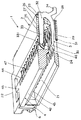
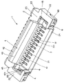
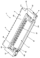
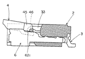
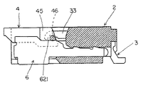
図1、2及び図3、4に実施形態のFPC用コネクタ1が示されている。このFPC用コネクタ1は、絶縁ハウジング2と、複数の端子3と、アクチュエータ4とを備えている。絶縁ハウジング2とアクチュエータ4は、絶縁性のプラスチックで成形されている。端子3は、薄金属板を打ち抜いて成形されている。アクチュエータ4は、図1、3に示されている第1の位置(開放位置)と、図2、4に示されている第2の位置(閉鎖位置)の間で回動可能とされている。アクチュエータ4が第1の位置にあるときは、絶縁ハウジング2に設けられているFPC挿入空間21にFPC5(図17参照)を挿入することが可能となる。また、アクチュエータ4が第2の位置にあるときは、アクチュエータ4に設けられている加圧面41が、FPC挿入空間21に挿入されたFPC5を端子3のコンタクト片31に向けて押圧付勢することができ、FPC5と端子3を電気的に接続する。
【0015】
絶縁ハウジング2は、図1〜4、特に図1、3に示されているように、細幅の板状で、中間部前方(図において手前側)がくりぬかれた形状とされて、FPC挿入空間21、側壁22、後壁23、底壁24が画成されている。FPC挿入空間21は、前方と上方が開放している。後壁23には頂壁25が一体に設けられ、FPC挿入空間21側にひさし状となって延びている。後壁23の上部には、長手方向に所定のピッチで端子装着孔26が形成されている。この端子装着孔26は、頂壁25に形成された端子受入溝27に連続している。また、端子装着孔26に対応させて、後壁24の下部には、コンタクト挿入孔28が形成されている。コンタクト挿入孔28に連続するようにして、底壁24にはコンタクト受入溝29が形成されている。
【0016】
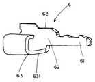
絶縁ハウジング2の両側壁22には、図3、4に表れているように、それぞれ支持金具6が側壁22に沿って装着されている。この支持金具6は、比較的厚い金属板を打ち抜いて図5のように成形したものである。絶縁ハウジング2の側壁22内に圧入されて係止する係止部分61に幅広の支持部分62が連続しており、また、支持部分62の下部に、屈曲して折り返されたネール部分63が連続している。一方の側壁22に装着される支持金具6と、他方の側壁22に装着される支持金具6は、係止部分61と支持部分62に対してネール部分63が互いに反対の側に連続している。
【0017】
側壁22に装着された支持金具6は、支持部分62の上縁部が、図1、3、4に表れているように、FPC挿入空間21の側部において露出している。また、支持金具6のネール部分63は、その下面631が絶縁ハウジング2の底壁24の下面と略面一となって、取付基板(図示せず)上に半田付けができるようにされている。
【0018】
FPC挿入空間21の側部において露出している支持金具6の支持部分62は、上部側縁に平坦な面621が形成されており、以下で説明するように、アクチュエータ4に対する第1支持部分を構成している。
【0019】
複数の端子3は、絶縁ハウジング2の各端子装着孔26に一つずつ装着されている。各端子3は、図1、2に表れているように、端子装着孔26に挿入されて係止する装着片32から支持アーム33が直線的に延びるとともに、装着片32からコンタクト片31が弧状に延びた形状をしており、支持アーム33とコンタクト片31が二股状となっている。支持アーム33は、絶縁ハウジング2の頂壁25に形成した端子受入溝27に沿って延びて、FPC挿入空間21の上部に臨む長さを有している。コンタクト片31は、絶縁ハウジング2のコンタクト挿入孔28を通してコンタクト受入溝29に沿って延びて、FPC挿入空間21の下部に片持ち梁状となって臨む長さを有している。コンタクト片31の先端部上縁には、コンタクト部311が突起状に形成されており、FPC挿入空間21に挿入されるFPC5の下面と対向できるようにされている。
【0020】
端子3のコンタクト片31の基部からはテール片34が外向きに分岐して設けられており、絶縁ハウジング2の底壁24の下面と略面一となって、前記ネール部分63と同様に、取付基板へ半田付けができるようにされている。
【0021】
端子3のコンタクト片31は、絶縁ハウジング2のコンタクト挿入孔28とコンタクト受入溝29の中でフリーの状態となっており、コンタクト片31の略全長に亘る部分が図の上下の方向で弾性変形が可能となっている。これに対して、端子3の支持アーム33は、装着片32に近いおよそ半分の長さに亘る部分が、上縁を絶縁ハウジング2の頂壁25でバックアップされて上方向への変形が拘束されている。支持アーム33の先端側のおよそ半分の長さに亘る部分は、FPC挿入空間21でフリーの状態とされ、上下の方向で弾性変形が可能となっているが、コンタクト片31に比べると弾性変形がしにくくなっている。
【0022】
この弾性変形が可能な部分とされた支持アーム33の先端部下縁には、切欠凹部331が形成されている。この切欠凹部331は、以下で説明するように、アクチュエータ4に対する第2支持部分を構成している。
【0023】
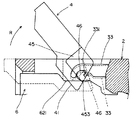
次に、アクチュエータ4の構成について説明する。このアクチュエータ4は、図1〜図4に明らかなように、略方形の細長い板状をしており、絶縁ハウジング2に形成されたFPC挿入空間21の上部に収容できる大きさとなっている。回動の操作部となる先端42側の下面にテーパ面43が形成されて、先端42側が中間部から徐々に薄くなるようにしてある。後端44側は逆に、下面側が突出するように中間部より厚く形成され、この下面がFPC5に対する加圧面41となっている。
【0024】
基本的な形状を上記の如くにしたアクチュエータ4は、回動の際の回動軸が後端44側に沿って形成されるように、第1の軸45と複数の第2の軸46が設けられている。第1の軸45は後端44側の両端に回動軸方向で突出して設けられている。この第1の軸45は、断面が略台形とされ(図6参照)、前記支持金具6の支持部分62の側縁に形成した平坦な面621、即ち第1支持部分に載置されている。
【0025】
アクチュエータ4の第2の軸46は、アクチュエータ4の後端44側に形成された複数の貫通孔47の中に、回動軸方向で設けられている。この第2の軸46は、基本的に断面が略円形とされている。複数の貫通孔47は、絶縁ハウジング2に装着した端子3の支持アーム33に、1対1で対応するように形成されている。アクチュエータ4を組み付けると、各支持アーム33が貫通孔47に進入し、支持アーム33の先端部下縁に形成した切欠凹部331、即ち第2支持部分に、断面が略円形とされた第2の軸46が収容されるようにしてある。支持アーム33の切欠凹部331は弧状とされ、この弧状縁に第2の軸46の周面が接するようにされている。
【0026】
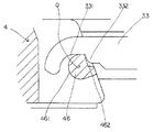
図6、7には、前記第1の軸45が第1支持部分621に支持されている部分が示されている。また、図8には、前記第2の軸46が第2支持部分331に支持されている部分が示されている。図6、7に明確に示されているように、第1の軸45は、台形の斜辺に相当する側面で構成される第1停止面451と、台形の底辺に相当する側面で構成される第2停止面452と、これら第1、第2停止面451、452に挟まれた円弧面453を有している。したがって、アクチュエータ4が回動する時には、支持金具6の平坦な面(第1支持部分)621で支持される第1の軸45は、円弧面453が平坦な面621に接した状態で、円弧面453の中心点Pを回動中心として回動するようにされている。また、アクチュエータ4が第1の位置(開放位置)にある時は、第1停止面451が平坦な面(第1支持部分)621に接し、第2の位置(閉鎖位置)にある時は、第2停止面452が平坦な面(第1支持部分)621に接するようにされている。
【0027】
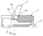
図8を参照して、第2の軸46について説明すると、この実施形態では、第2の軸46はおよそ半円に相当する円弧面461と、係合凹部462とを有している。アクチュエータ4が回動する時には、端子3の支持アーム33に形成された切欠凹部(第2支持部分)331に収容されるこの第2の軸46は、円弧面461が切欠凹部331の縁に接した状態で、円弧面461の中心点Qを回動中心として回動するようにされている。また、アクチュエータ4が第2の位置(閉鎖位置)にある時は、弧状の切欠凹部331に突出するように設けた突部332と係合凹部462が係合するようにされている。
【0028】
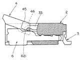
前記第1の軸45の円弧面453の中心点Pと、第2の軸46の円弧面461も中心点Qは、図9、10に示されているように、オフセット(偏心)している。つまり、アクチュエータ4を第2の位置(閉鎖位置)から第1の位置(開放位置)に向けて、図の矢示Rのように回動させる時には、第2の軸46の円弧面461の中心点Qが、図9の矢示rのように、第1の軸45に対する第1支持部分621から離れる方向へ移動するようにされている。即ち、第2の軸46が、図10に点線で示した位置から実線で示す位置へと移動するようにされている。そして、この中心点Qの移動は、端子3の支持アーム33の矢示F方向(図9)への弾性変形を伴い(図10では、点線で示した位置から実線で示した位置へと変形)、この弾性変形の反力が第2の軸46に作用して、中心点Qのこのような移動を阻止するようにされている。したがって、アクチュエータ4の回動には、この支持アーム33の弾性反力に打ち勝つだけの力を必要とするようになっている。
【0029】
加えて、この実施形態では、支持アーム33の切欠凹部(第2支持部分)331に突部332を設けて、第2の軸46の係合凹部462に係合させるようにしたので、第2の軸46は、後方(図9において右方向)への移動が拘束されている。したがって、アクチュエータ4を矢示Rの方向へ回動させる時には、第1の軸45の円弧面453が第1支持部分(平坦な面)621に沿って前方(図9において左方向)へ摩擦に打ち勝って摺動させる必要が有り、このための力もアクチュエータ4に加えなければならないものとなっている。
【0030】
以上のように構成された実施形態のFPC用コネクタ1の、アクチュエータ4の回動の様子が図11から図17に亘って順次示されている。FPC5を接続する時は、図11のようにアクチュエータ4を第1の位置(開放位置)に回動させて、FPC挿入空間21を開放し、FPC5の接続端部を挿入する。FPC5を挿入した後、アクチュエータ4を図12、13、・・・を経て、図17の第2の位置(閉鎖位置)まで回動させる。この接続時のアクチュエータ4の回動には、端子3の支持アーム33の弾性反力も加わる。アクチュエータ4が第2の位置に到達すると、アクチュエータ4が前記のように端子3の支持アーム33の弾性反力を受けて、これによってアクチュエータ4の加圧面41がFPC5の表面へ衝突するように接するので、この時「パチン」と音を発して、操作者にクリック感を与えることができると共に、アクチュエータ4は再現性良く第2の位置で停止させることができる。
【0031】
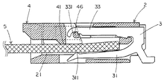
図18には、FPC5が挿入された状態が示されている。アクチュエータ4が第2の位置では、加圧面41がFPC5を端子3のコンタクト片31に向けて押圧付勢し、コンタクト片31のコンタクト部311とFPC5の接点を適度の接触圧で当接させて、電気的な接続を形成する。アクチュエータ4の第2の位置の再現性が良いために、コンタクト部311と接点の接触圧も、再現性良く、一定の圧力を確保し、常に安定な接続状態を形成することができる。
【0032】
FPC5が接続されたアクチュエータ4の第2の位置は、その位置に安定的に保持することができる。即ち、不用意にアクチュエータ4が第1の位置に向かって回動しようとすると、図9、10を用いて説明したように、端子3の支持アーム33を弾性変形させることとなるために、その弾性反力がそのような回動を阻止するように働く。したがって、アクチュエータ4は第2の位置に保持されて、安定な接続状態を確実に維持することができる。
【0033】
このアクチュエータ4の第2の位置(閉鎖位置)から第1の位置(開放位置)に向かう不用意な回動は、FPC5が挿入されていない場合でも阻止することができる。アクチュエータ4がFPC5を加圧しているかいないかに拘わらず、アクチュエータ4が第1の位置に向かって回動する時には、支持アーム33の弾性変形を伴うためである。したがって、このFPC用コネクタ1を輸送する際や、取付基板に実装する際などに、第2の位置においたアクチュエータ4が不用意に第1の位置に向かって回動するのを阻止することができる。
【0034】
このように、アクチュエータ4の不用意な回動が、端子3の支持アーム33が発揮する弾性反力で阻止できるので、アクチュエータ4と絶縁ハウジング2の間では、図19、20、21に示すような第2の位置(閉鎖位置)を維持するための係合構造は設けなくてよくできる。したがって、係合構造のためにさかなければならない部分(スペース)を無くすることができるので、FPC用コネクタ1の小型化を図る際の障害を除くことができる。
【0035】
FPC5の接続を解除する場合は、アクチュエータ4を図17の第2の位置から、図16、15、・・・を経て図11の第1の位置まで回動させる。この場合、端子3の支持アーム33の弾性反力に打ち勝つ力と、第1の軸45の円弧面453と第1支持部分(平坦な面)621の摩擦に打ち勝つ力を加えることになる。アクチュエータ4が第1の位置に到達すると、第1の軸45の第1停止面451が第1支持部分である平坦な面621に接して、その位置が固定されるので、FPC5を抜き出したり、再度挿入する作業を、アクチュエータ4に邪魔されることなく行うことができる。
【0036】
以上で説明した実施形態のFPC用コネクタ1では、全ての端子3に支持アーム33を設けて、アクチュエータ4の対応する第2の軸46と係合させているが、端子3の極数に比例して支持アーム33の弾性反力が増強されることとなるので、端子3の極数に応じて、支持アーム33を設ける端子3を減らすこともできる。例えば、1極おきの端子3に支持アーム33を設けるようにすることができる。少なくとも一つの端子3に支持アーム33を設けて、上記のように不用意なアクチュエータ4の回動を阻止することができる。
【0037】
【発明の効果】
以上に説明したように、この発明のFPC用コネクタは、FPCが接続されているか、いないかに拘わらず、アクチュエータの第2の軸の移動で生じる弾性反力でアクチュエータの第2の位置(閉鎖位置)から第1の位置(開放位置)に向かう不用意な回動を阻止できる構成なので、接続状態を安定に維持できると共に、アクチュエータと絶縁ハウジングの間に係合構造を不要として小型化を図ることができる効果がある。
【図面の簡単な説明】
【図1】この発明の実施形態のFPC用コネクタの、アクチュエータが第1の位置にある時の、一部を破断して示した斜視図である。
【図2】同じく、アクチュエータが第2の位置にある時の、一部を破断して示した斜視図である。
【図3】実施形態のFPC用コネクタの、アクチュエータが第1の位置にある時の斜視図である。
【図4】同じく、アクチュエータが第2の位置にある時の斜視図である。
【図5】実施形態のFPC用コネクタに設けられた支持金具の斜視図である。
【図6】実施形態のFPC用コネクタの、第1の軸が第1支持部分に支持されている部分の拡大断面図である。
【図7】実施形態のFPC用コネクタの第1の軸が第1支持部分に支持されている部分の拡大斜視図(絶縁ハウジングを除く)である。
【図8】実施形態のFPC用コネクタの、第2の軸が第2支持部分に支持されている部分の拡大断面図である。
【図9】実施形態のFPC用コネクタの、第1の軸と第2の軸の回動中心を説明する図である。
【図10】実施形態のFPC用コネクタのアクチュエータを第2の位置から第1の位置へ回動させる時の回動の変化を示す図である。
【図11】実施形態のFPC用コネクタの、アクチュエータが第1の位置にある時の断面図である。
【図12】図11の状態からアクチュエータを第2の位置に向かって回動する途中の断面図である。
【図13】図12の状態からアクチュエータを第2の位置に向かって更に回動する途中の断面図である。
【図14】図13の状態からアクチュエータを第2の位置に向かって更に回動する途中の断面図である。
【図15】図14の状態からアクチュエータを第2の位置に向かって更に回動する途中の断面図である。
【図16】図15の状態からアクチュエータを第2の位置に向かって更に回動する途中の断面図である。
【図17】実施形態のFPC用コネクタの、アクチュエータが第2の位置にある時の断面図である。
【図18】実施形態のFPC用コネクタにFPCが接続されている状態の断面図である。
【図19】従来のFPC用コネクタの平面図である。
【図20】同じく、従来のFPC用コネクタの正面図である。
【図21】図18のA部の拡大図である。
【符号の説明】
1 FPC用コネクタ
2 絶縁ハウジング
21 FPC挿入空間
22 側壁
23 後壁
24 底壁
25 頂壁
26 端子装着孔
27 端子受入溝
28 コンタクト挿入孔
29 コンタクト受入溝
3 端子
31 コンタクト片
311 コンタクト部
32 装着片
33 支持アーム
331 切欠凹部(第2支持部分)
332 突部
34 テール片
4 アクチュエータ
41 加圧面
42 先端
43 テーパ面
44 後端
45 第1の軸
451 第1停止面
452 第2停止面
453 円弧面
46 第2の軸
461 円弧面
462 係合凹部
47 貫通孔
5 FPC
6 支持金具
61 係止部分
62 支持部分
621 平坦な面(第1支持部分)
63 ネール部分
631 下面[0001]
TECHNICAL FIELD OF THE INVENTION
BACKGROUND OF THE INVENTION 1. Field of the Invention The present invention relates to an FPC connector for connecting a flat flexible cable generally referred to as an FPC, FFC, or the like (in this specification, these are simply referred to as "FPC").
[0002]
[Prior art]
Conventionally, this type of connector is composed of an insulating housing provided with an FPC insertion space, and a plurality of terminals mounted in parallel on the insulating housing at a predetermined pitch. , A first position (open position) at which the FPC can be inserted into the FPC insertion space, and a second position (closed) for urging the inserted FPC toward the contact piece of the terminal. (Position) between the actuator and the actuator.
[0003]
The rotation of the actuator between the first position and the second position is shown in FIGS. 3, 4 and 5 of Utility Model Registration No. 2580074, and FIGS. 2 and 3 of Japanese Patent Application Laid-Open No. 2001-307829. Further, as shown in FIG. 1 of Japanese Patent Application Laid-Open No. 2002-289283, it is configured to rotate around a substantially fixed rotation axis, and Japanese Utility Model Registration No. 3035692. As shown in FIG. 1 to FIG. 10 sequentially, there is known an apparatus in which the center of rotation is rotated while moving.
[0004]
As shown in FIG. 5 of Japanese Patent Application Laid-Open No. 2002-289283, in order to prevent the actuator rotatably provided in the second position from inadvertently rotating in the direction of the first position. As described above, the restraining wings 55 and the engaging pieces (not shown) provided in the shape of the hanging pieces at both ends on the operation end side of the actuator (pressing member) 56 are engaged with each other. The state where the actuator is in the second position is a state in which the FPC inserted into the insulating housing and the terminal are electrically connected, and such a configuration is employed to stably maintain the connection state.
[0005]
As a structure for holding the position of the actuator at the second position, a structure as shown in FIGS. 19 to 21 is also known. In the figure, a is an insulating housing, b is a terminal, and c is an actuator. Projections c1 having a semicircular cross section are provided on both end surfaces of the actuator c so as to engage with arcuate concave locking portions a2 formed on the inner surfaces of both side walls a1 of the insulating housing a.
[0006]
In addition to the above, the mechanism for restricting the rotation of the actuator uses the elastic reaction force of the contact piece of the terminal as disclosed in Japanese Utility Model Registration No. 2580074 or JP-A-2001-307829. There is also known a configuration in which an actuator is biased in a closing direction. Japanese Utility Model Registration No. 2580074 describes this in paragraphs [0019] to [0021], particularly [0021] of the specification. Japanese Patent Application Laid-Open No. 2001-307829 describes this in paragraphs [0011] and [0013] of the specification.
[0007]
[Problems to be solved by the invention]
Of the above-described configurations in which the actuator is prevented from being accidentally rotated, the former in which the engagement structure is provided between the actuator and the insulating housing is the height of the connector or the width of the terminals in parallel. Since a certain area in the connector has to be cut in a direction or the like, it is difficult to reduce the size of the connector.
In the latter case in which the elastic reaction force of the contact piece is used, the elastic reaction force of the contact piece does not work unless the FPC is connected to the connector. For this reason, during transportation or mounting on a mounting board before connecting the FPC, the actuator is inadvertently rotated (opened) due to an external impact.
[0008]
The present invention has been made in view of such circumstances, and regardless of whether or not the FPC is connected, the actuator in the closed position (the second position) is inadvertently opened (the first position). It is an object of the present invention to provide an FPC connector that does not rotate in the direction of.
[0009]
[Means for Solving the Problems]
An object of the present invention is to provide an insulating housing provided with an FPC insertion space according to the present invention,
A plurality of terminals mounted in parallel on the insulating housing at a predetermined pitch, wherein a plurality of contact pieces provided respectively face the FPC insertion space;
An actuator provided rotatably between a first position at which the FPC can be inserted into the FPC insertion space and a second position at which the inserted FPC is biased toward the contact piece of the terminal;
The actuator has a first shaft provided at both ends in the rotation axis direction, and a second shaft provided between the first shafts at both ends,
When the actuator is rotated from the second position toward the first position, the first shaft is moved so that the center of rotation of the second shaft moves away from the first support portion with respect to the first shaft. An FPC wherein the center of rotation of the shaft and the center of rotation of the second shaft are offset, and the second shaft is pivotally supported by a second support portion that elastically blocks the movement. Connector.
[0010]
[Action]
According to the FPC connector of the present invention configured as described above, the first shaft and the second shaft are provided in the actuator in an offset state, and the second shaft is formed by the second support portion capable of exhibiting an elastic reaction force. Since the connector is pivotally supported, the actuator at the second position (closed position) moves toward the first position (opened position) regardless of whether the FPC is connected to the connector or not. If the user attempts to rotate the device inadvertently, an elastic reaction force acts on the second shaft from the second support portion, thereby preventing the rotation.
[0011]
The first shaft of the actuator is provided to protrude from both ends on the rear end side of the actuator, and is mounted on a first support portion having a flat surface provided on the insulating housing side, and is rotated. It is preferable to support as much as possible. In this case, the first support portion provided on the insulating housing side may be provided integrally with the insulating housing. However, as described in
[0012]
Further, the second shaft of the actuator is housed in a second support portion formed by a cutout recess of the support arm integrally extending from the terminal, and the elastic force is applied to the support arm. However, it is also possible to form such a second support portion directly and integrally with the insulating housing. The support arm provided integrally with the terminal can be provided on all the terminals mounted on the insulating housing as in the embodiment described below, but is not limited to this. In addition, the present invention is included as long as it is provided in at least one terminal.
[0013]
BEST MODE FOR CARRYING OUT THE INVENTION
Hereinafter, an FPC connector according to an embodiment of the present invention will be described in detail.
[0014]
1, 2 and 3 and 4 show an FPC connector 1 according to an embodiment. The FPC connector 1 includes an insulating
[0015]
As shown in FIGS. 1 to 4, and particularly FIGS. 1 and 3, the insulating
[0016]
As shown in FIGS. 3 and 4, the
[0017]
The support fitting 6 attached to the
[0018]
The
[0019]
The plurality of
[0020]
A
[0021]
The
[0022]
A
[0023]
Next, the configuration of the
[0024]
In the
[0025]
The
[0026]
FIGS. 6 and 7 show a portion where the
[0027]
Referring to FIG. 8, the
[0028]
The center point P of the
[0029]
In addition, in this embodiment, the
[0030]
The rotation of the
[0031]
FIG. 18 shows a state where the
[0032]
The second position of the
[0033]
This careless rotation of the
[0034]
In this manner, the inadvertent rotation of the
[0035]
When the connection of the
[0036]
In the FPC connector 1 of the embodiment described above, all the
[0037]
【The invention's effect】
As described above, the FPC connector according to the present invention is capable of controlling the second position (closed position) of the actuator by the elastic reaction force generated by the movement of the second axis of the actuator regardless of whether the FPC is connected or not. Position) to prevent the inadvertent rotation from the first position (the open position) to the first position (the open position), so that the connection state can be stably maintained, and the size of the actuator can be reduced by eliminating the need for an engagement structure between the actuator and the insulating housing. There are effects that can be.
[Brief description of the drawings]
FIG. 1 is a partially cutaway perspective view of an FPC connector according to an embodiment of the present invention when an actuator is at a first position.
FIG. 2 is a perspective view showing a part of the actuator when the actuator is at a second position.
FIG. 3 is a perspective view of the FPC connector of the embodiment when an actuator is at a first position.
FIG. 4 is a perspective view when the actuator is in a second position.
FIG. 5 is a perspective view of a support fitting provided on the FPC connector of the embodiment.
FIG. 6 is an enlarged cross-sectional view of a portion of the FPC connector according to the embodiment, in which a first shaft is supported by a first support portion.
FIG. 7 is an enlarged perspective view (excluding an insulating housing) of a portion where a first shaft of the FPC connector of the embodiment is supported by a first support portion.
FIG. 8 is an enlarged cross-sectional view of a portion of the FPC connector according to the embodiment, in which a second shaft is supported by a second support portion.
FIG. 9 is a diagram illustrating a center of rotation of a first shaft and a second shaft of the FPC connector of the embodiment.
FIG. 10 is a diagram showing a change in rotation when the actuator of the FPC connector according to the embodiment is rotated from a second position to a first position.
FIG. 11 is a cross-sectional view of the FPC connector of the embodiment when the actuator is at a first position.
FIG. 12 is a cross-sectional view in the course of rotating the actuator from the state of FIG. 11 toward the second position.
FIG. 13 is a cross-sectional view showing a state where the actuator is further rotated from the state of FIG. 12 toward the second position.
FIG. 14 is a cross-sectional view showing a state where the actuator is further rotated from the state shown in FIG. 13 toward the second position.
FIG. 15 is a cross-sectional view showing a state where the actuator is further rotated from the state shown in FIG. 14 toward the second position.
FIG. 16 is a cross-sectional view showing a state where the actuator is further rotated from the state of FIG. 15 toward the second position.
FIG. 17 is a cross-sectional view of the FPC connector of the embodiment when the actuator is at a second position.
FIG. 18 is a cross-sectional view showing a state where the FPC is connected to the FPC connector of the embodiment.
FIG. 19 is a plan view of a conventional FPC connector.
FIG. 20 is a front view of a conventional FPC connector.
21 is an enlarged view of a portion A in FIG.
[Explanation of symbols]
REFERENCE SIGNS LIST 1
332
6
63
Claims (6)
絶縁ハウジング(2)に所定のピッチで並列して装着された複数の端子(3)であって、それぞれに設けられたコンタクト片(31)が前記FPC挿入空間(21)に臨んでいる複数の端子(3)と、
FPC挿入空間(21)にFPC(5)を挿入可能とする第1の位置と、挿入されたFPC(5)を端子(3)のコンタクト片(31)に向けて付勢する第2の位置の間で回動可能に設けられたアクチュエータ(4)とを備え、
前記アクチュエータ(4)が、回動軸方向で両端部に設けられた第1の軸(45)と、この両端部の第1の軸(45)の間に設けられた第2の軸(46)を有しており、
アクチュエータ(4)を前記第2の位置から第1の位置に向けて回動する時、第2の軸(46)の回動中心(Q)が第1の軸(45)に対する第1支持部分(621)から離れる方向へ移動するように、第1の軸(45)の回動中心(P)と第2の軸(46)の回動中心(Q)がオフセットしていると共に、第2の軸(46)が前記移動を弾性的に阻止する第2支持部分(331)で軸支されていることを特徴とするFPC用コネクタ(1)。An insulating housing (2) provided with an FPC insertion space (21);
A plurality of terminals (3) mounted in parallel on the insulating housing (2) at a predetermined pitch, and a plurality of contact pieces (31) provided respectively face the FPC insertion space (21). Terminal (3),
A first position at which the FPC (5) can be inserted into the FPC insertion space (21), and a second position at which the inserted FPC (5) is biased toward the contact piece (31) of the terminal (3). An actuator (4) rotatably provided between the
The actuator (4) is provided with a first shaft (45) provided at both ends in the rotation axis direction and a second shaft (46) provided between the first shafts (45) at the both ends. )
When the actuator (4) is rotated from the second position toward the first position, the center of rotation (Q) of the second shaft (46) is moved to the first support portion with respect to the first shaft (45). The rotation center (P) of the first shaft (45) and the rotation center (Q) of the second shaft (46) are offset so as to move in a direction away from (621), and the second shaft (46) is offset. The connector (1) for an FPC, wherein the shaft (46) is pivotally supported by a second support portion (331) for elastically preventing the movement.
Priority Applications (3)
| Application Number | Priority Date | Filing Date | Title |
|---|---|---|---|
| JP2002362008A JP3632106B2 (en) | 2002-12-13 | 2002-12-13 | FPC connector |
| MYPI20034749A MY138776A (en) | 2002-12-13 | 2003-12-11 | Fpc connector |
| CN2003101147490A CN1549401B (en) | 2002-12-13 | 2003-12-12 | Fpc connector |
Applications Claiming Priority (1)
| Application Number | Priority Date | Filing Date | Title |
|---|---|---|---|
| JP2002362008A JP3632106B2 (en) | 2002-12-13 | 2002-12-13 | FPC connector |
Publications (2)
| Publication Number | Publication Date |
|---|---|
| JP2004193045A true JP2004193045A (en) | 2004-07-08 |
| JP3632106B2 JP3632106B2 (en) | 2005-03-23 |
Family
ID=32760578
Family Applications (1)
| Application Number | Title | Priority Date | Filing Date |
|---|---|---|---|
| JP2002362008A Expired - Lifetime JP3632106B2 (en) | 2002-12-13 | 2002-12-13 | FPC connector |
Country Status (3)
| Country | Link |
|---|---|
| JP (1) | JP3632106B2 (en) |
| CN (1) | CN1549401B (en) |
| MY (1) | MY138776A (en) |
Cited By (9)
| Publication number | Priority date | Publication date | Assignee | Title |
|---|---|---|---|---|
| US7112079B2 (en) | 2004-10-26 | 2006-09-26 | J.S.T. Mfg. Co., Ltd. | Flexible printed circuit board connector |
| JP2007179760A (en) * | 2005-12-27 | 2007-07-12 | Molex Inc | Cable connecting connector |
| KR100826744B1 (en) * | 2005-09-20 | 2008-04-30 | 니혼 고꾸 덴시 고교 가부시끼가이샤 | Connector having an actuator which is stably operable |
| JP2010056066A (en) * | 2008-07-29 | 2010-03-11 | Yamaichi Electronics Co Ltd | Cable connector |
| EP1976067A3 (en) * | 2007-03-27 | 2010-11-03 | Panasonic Electric Works Co., Ltd. | Cable connector |
| JP2012099498A (en) * | 2012-01-17 | 2012-05-24 | Molex Inc | Connector for cable connection |
| KR101367823B1 (en) | 2011-11-01 | 2014-02-26 | 니혼 고꾸 덴시 고교 가부시끼가이샤 | Connector |
| KR20150009918A (en) | 2013-07-17 | 2015-01-27 | 니혼 고꾸 덴시 고교 가부시끼가이샤 | Connector |
| CN114142280A (en) * | 2020-09-03 | 2022-03-04 | 泰科电子连接印度私有有限公司 | Angled connector and method of assembling an angled connector |
Families Citing this family (2)
| Publication number | Priority date | Publication date | Assignee | Title |
|---|---|---|---|---|
| JP4566076B2 (en) * | 2005-06-29 | 2010-10-20 | タイコエレクトロニクスジャパン合同会社 | connector |
| CN102055093A (en) * | 2009-11-07 | 2011-05-11 | 昆山玉鼎精密模具股份有限公司 | Electric connector |
Family Cites Families (1)
| Publication number | Priority date | Publication date | Assignee | Title |
|---|---|---|---|---|
| JP3786400B2 (en) * | 2001-03-23 | 2006-06-14 | ヒロセ電機株式会社 | Electric connector for flat cable and method for manufacturing the same |
-
2002
- 2002-12-13 JP JP2002362008A patent/JP3632106B2/en not_active Expired - Lifetime
-
2003
- 2003-12-11 MY MYPI20034749A patent/MY138776A/en unknown
- 2003-12-12 CN CN2003101147490A patent/CN1549401B/en not_active Expired - Lifetime
Cited By (11)
| Publication number | Priority date | Publication date | Assignee | Title |
|---|---|---|---|---|
| US7112079B2 (en) | 2004-10-26 | 2006-09-26 | J.S.T. Mfg. Co., Ltd. | Flexible printed circuit board connector |
| KR100826744B1 (en) * | 2005-09-20 | 2008-04-30 | 니혼 고꾸 덴시 고교 가부시끼가이샤 | Connector having an actuator which is stably operable |
| JP2007179760A (en) * | 2005-12-27 | 2007-07-12 | Molex Inc | Cable connecting connector |
| EP1976067A3 (en) * | 2007-03-27 | 2010-11-03 | Panasonic Electric Works Co., Ltd. | Cable connector |
| JP2010056066A (en) * | 2008-07-29 | 2010-03-11 | Yamaichi Electronics Co Ltd | Cable connector |
| KR101367823B1 (en) | 2011-11-01 | 2014-02-26 | 니혼 고꾸 덴시 고교 가부시끼가이샤 | Connector |
| US8936479B2 (en) | 2011-11-01 | 2015-01-20 | Japan Aviation Electronics Industry, Limited | Connector having first and second types of contacts with support members to support an actuator |
| JP2012099498A (en) * | 2012-01-17 | 2012-05-24 | Molex Inc | Connector for cable connection |
| KR20150009918A (en) | 2013-07-17 | 2015-01-27 | 니혼 고꾸 덴시 고교 가부시끼가이샤 | Connector |
| US9225097B2 (en) | 2013-07-17 | 2015-12-29 | Japan Aviation Electronics Industry, Limited | Electrical connector having a guard portion |
| CN114142280A (en) * | 2020-09-03 | 2022-03-04 | 泰科电子连接印度私有有限公司 | Angled connector and method of assembling an angled connector |
Also Published As
| Publication number | Publication date |
|---|---|
| JP3632106B2 (en) | 2005-03-23 |
| MY138776A (en) | 2009-07-31 |
| CN1549401A (en) | 2004-11-24 |
| CN1549401B (en) | 2010-05-26 |
Similar Documents
| Publication | Publication Date | Title |
|---|---|---|
| JP2976327B2 (en) | connector | |
| JP3099102U (en) | connector | |
| JP2892945B2 (en) | Electrical connector for flexible board | |
| US6726497B2 (en) | Connector for flat flexible cable | |
| JP2007048499A (en) | Electrical connector for flat cable | |
| JP3391431B2 (en) | Connector for sheet-shaped conductive path | |
| JP2005056824A (en) | Electric connector | |
| JP4054741B2 (en) | ZIF connector for low profile FPC | |
| JP2004193045A (en) | Fpc connector | |
| JP2002083638A (en) | Terminal for substrate connection and connector using the same | |
| JP4054740B2 (en) | ZIF connector for FPC | |
| KR101495785B1 (en) | Electric connector | |
| JP2001110483A (en) | Connector for cable | |
| JP3019288U (en) | Electrical connector for flat flexible cable | |
| JP2010003458A (en) | Connector device | |
| JP2009252538A (en) | Connector device | |
| JP2003317838A (en) | Connector for flexible board | |
| JP2006032285A (en) | Socket | |
| JP2580074Y2 (en) | Electrical connector for flexible board | |
| JPH10208822A (en) | Connector for sheet conducting path | |
| JP2004319349A (en) | Connector for fpc | |
| JP2008300340A (en) | Connector | |
| JP2004192825A (en) | Connector for fpc | |
| JP2001143827A (en) | Connector for plate shaped object | |
| JPH10270130A (en) | Connector for sheet-like conductive path |
Legal Events
| Date | Code | Title | Description |
|---|---|---|---|
| A621 | Written request for application examination |
Free format text: JAPANESE INTERMEDIATE CODE: A621 Effective date: 20040909 |
|
| A871 | Explanation of circumstances concerning accelerated examination |
Free format text: JAPANESE INTERMEDIATE CODE: A871 Effective date: 20040914 |
|
| A975 | Report on accelerated examination |
Free format text: JAPANESE INTERMEDIATE CODE: A971005 Effective date: 20040928 |
|
| TRDD | Decision of grant or rejection written | ||
| A01 | Written decision to grant a patent or to grant a registration (utility model) |
Free format text: JAPANESE INTERMEDIATE CODE: A01 Effective date: 20041012 |
|
| A61 | First payment of annual fees (during grant procedure) |
Free format text: JAPANESE INTERMEDIATE CODE: A61 Effective date: 20041206 |
|
| R150 | Certificate of patent or registration of utility model |
Free format text: JAPANESE INTERMEDIATE CODE: R150 Ref document number: 3632106 Country of ref document: JP Free format text: JAPANESE INTERMEDIATE CODE: R150 |
|
| FPAY | Renewal fee payment (event date is renewal date of database) |
Free format text: PAYMENT UNTIL: 20090107 Year of fee payment: 4 |
|
| R250 | Receipt of annual fees |
Free format text: JAPANESE INTERMEDIATE CODE: R250 |
|
| FPAY | Renewal fee payment (event date is renewal date of database) |
Free format text: PAYMENT UNTIL: 20100107 Year of fee payment: 5 |
|
| R250 | Receipt of annual fees |
Free format text: JAPANESE INTERMEDIATE CODE: R250 |
|
| FPAY | Renewal fee payment (event date is renewal date of database) |
Free format text: PAYMENT UNTIL: 20110107 Year of fee payment: 6 |
|
| R250 | Receipt of annual fees |
Free format text: JAPANESE INTERMEDIATE CODE: R250 |
|
| FPAY | Renewal fee payment (event date is renewal date of database) |
Free format text: PAYMENT UNTIL: 20120107 Year of fee payment: 7 |
|
| R250 | Receipt of annual fees |
Free format text: JAPANESE INTERMEDIATE CODE: R250 |
|
| FPAY | Renewal fee payment (event date is renewal date of database) |
Free format text: PAYMENT UNTIL: 20130107 Year of fee payment: 8 |
|
| R250 | Receipt of annual fees |
Free format text: JAPANESE INTERMEDIATE CODE: R250 |
|
| FPAY | Renewal fee payment (event date is renewal date of database) |
Free format text: PAYMENT UNTIL: 20130107 Year of fee payment: 8 |
|
| R250 | Receipt of annual fees |
Free format text: JAPANESE INTERMEDIATE CODE: R250 |
|
| R250 | Receipt of annual fees |
Free format text: JAPANESE INTERMEDIATE CODE: R250 |
|
| R250 | Receipt of annual fees |
Free format text: JAPANESE INTERMEDIATE CODE: R250 |
|
| S533 | Written request for registration of change of name |
Free format text: JAPANESE INTERMEDIATE CODE: R313533 |
|
| R350 | Written notification of registration of transfer |
Free format text: JAPANESE INTERMEDIATE CODE: R350 |
|
| R250 | Receipt of annual fees |
Free format text: JAPANESE INTERMEDIATE CODE: R250 |
|
| R250 | Receipt of annual fees |
Free format text: JAPANESE INTERMEDIATE CODE: R250 |
|
| R250 | Receipt of annual fees |
Free format text: JAPANESE INTERMEDIATE CODE: R250 |
|
| R250 | Receipt of annual fees |
Free format text: JAPANESE INTERMEDIATE CODE: R250 |
|
| R250 | Receipt of annual fees |
Free format text: JAPANESE INTERMEDIATE CODE: R250 |
|
| R250 | Receipt of annual fees |
Free format text: JAPANESE INTERMEDIATE CODE: R250 |
|
| R250 | Receipt of annual fees |
Free format text: JAPANESE INTERMEDIATE CODE: R250 |
|
| EXPY | Cancellation because of completion of term |