JP2004192033A - Coordinate input device - Google Patents
Coordinate input device Download PDFInfo
- Publication number
- JP2004192033A JP2004192033A JP2002355473A JP2002355473A JP2004192033A JP 2004192033 A JP2004192033 A JP 2004192033A JP 2002355473 A JP2002355473 A JP 2002355473A JP 2002355473 A JP2002355473 A JP 2002355473A JP 2004192033 A JP2004192033 A JP 2004192033A
- Authority
- JP
- Japan
- Prior art keywords
- coordinate
- mode
- input
- coordinates
- input device
- Prior art date
- Legal status (The legal status is an assumption and is not a legal conclusion. Google has not performed a legal analysis and makes no representation as to the accuracy of the status listed.)
- Withdrawn
Links
Images


Abstract
Description
【0001】
【発明の属する技術分野】
本発明は、表示システムと組み合わせて使用することにより、入出力一体の装置を構成することができる座標入力装置に関する。より詳しくは、ディスプレイの画面に指示具によって直接座標を入力したり、画面に対して離れたところから座標を入力することにより、外部接続されたコンピュータを制御したり、文字や図形などを書き込むために用いられる座標入力装置に関する。
【0002】
【従来の技術】
従来、CRTディスプレイ、液晶ディスプレイ(LCD)、あるいはプロジェクター等の表示装置の表示面に、座標を入力することができる座標入力装置を重ねて配置し、操作者が行ったポインティング、或いは筆記による筆跡をディスプレイに表示し、あたかも、紙と鉛筆のような関係を実現することができる装置が知られている。座標入力装置としては、抵抗膜方式をはじめ、静電方式、ガラス等の座標入力面に超音波を伝播させる超音波方式等、透明な入力板を有するものや、光学式、あるいは空中に音波を放射することで位置を検出する方式、さらには電磁誘導(電磁授受)方式の様に、表示装置の裏側に座標算出のための機構を配置し、表示装置の前面に透明な保護板を配置して、入出力一体の情報機器を構成しているものも有る。
【0003】
この様な機器は、携帯性を有する小型の電子手帳に始まって、ペン入力コンピュータ等、表示デバイスの大型化に伴って、比較的大きなサイズの情報機器も見られるようになった。そして、フロントプロジェクタ、リアプロジェクタ、あるいはPDP等の大型の表示装置と組み合わせて、例えばプレゼンテーション装置、TV会議システム等に利用され始めている。この大型の液晶ディスプレイやPDPディスプレイは、現在も画質の改善、低コスト化が進められており、衛星放送等のデジタル化に伴い、テレビの仕様形態も過渡期の状態に入りつつある。
【0004】
また、これらの大型表示装置は、例えばオフィスにおいて使われていたホワイトボード、あるいは電子黒板にとって変わり、パソコン内にあらかじめ用意した資料用データを大画面ディスプレイに表示させることで、会議用途、打ち合わせ用途に使われ始めている。その場合、表示用ディスプレイに表示された情報は、ホワイトボードの如く、操作者、あるいは出席者により表示情報を更新するために、直接画面をタッチすることで、パソコンを制御して、例えば表示スクリーンの表示内容を切り替えることができるように構成されている。
【0005】
【発明が解決しようとする課題】
しかしながら、この種の大型の入出力一体型システムを考慮した場合には、下記の課題があった。すなわち、大勢の参加者を想定した打ち合わせ、あるいはネットワークを介した使用環境を考慮すれば、操作者が直接画面をタッチすることでパソコンを制御するばかりではなく、例えば質問者がその場で遠隔操作により、画面を操作したり、その場で必要に応じてネットワークより情報を引き出せるような構成になるのが好ましい形態であると言える。
【0006】
従来、この種の装置は、画面に直接ペン先をタッチして入力する装置の場合には、指示する点をダイレクトに出力する絶対座標方式であり、アイコンなどの表示されている内容に対して、操作者はダイレクトに指示操作ができるため非常にアクセス性に優れるものである。
【0007】
一方で、画面から離れて入力(遠隔操作)する場合には、コンピュータを操作するマウスと同じように前回の座標に対する差分値でカーソルの移動量を算出する相対座標方式の装置が主流であった。したがって、画面に表示されている現状のカーソル位置を操作者が確認し、その位置から所望の位置までカーソルを移動させたり、アプリケーションによっては、カーソルが移動する軌跡として図形や文字等を描画したりできる。
【0008】
しかしながら、両者を同一装置で構成し、かつ両者を操作者が適宜切り替えるには困難性がともなった。
【0009】
すなわち、この種の装置での一連の入力動作は、まず、入力装置(例えばペンタイプ)に実装されたオン/オフを切り替えるボタンスイッチ等によって発信が制御され、ボタンスイッチをロックさせて入力装置を発信するモードに固定したならば、続いて所望の位置にカーソルを移動させる動作をする。そして、移動させたカーソル位置で描画やアイコンのクリック動作をさせるために、別のボタンスイッチを押す操作をする。そして操作者は、動作を終了させるために、発信を制御するボタンスイッチのロックを解除する。このように、入力操作するための一連の動作が非常に複雑である。
【0010】
それに加えて、絶対座標方式と相対座標方式を操作者が切り替えるには、表示画面に表示されているメニューから選択することによって、モードを切り替える方法が主であって、モードを切り替えるためにカーソルを移動させる必要であり、操作者にとって必ずしも操作性のよいものではなかった。
【0011】
本発明は、上記問題に鑑みてなされたものであり、表示画面に対する座標の入力を簡素化させるとともに操作者が所望する入力方式を容易に選択できる操作性に優れた座標入力装置を提供することを目的とする。
【0012】
【課題を解決するための手段】
上記目的を達成するため、本出願に係る発明は、座標入力面に対して所望の位置を指示して座標を入力する座標入力装置であって、位置を指示する位置指示手段と、該位置指示手段によって指示された座標を算出する座標算出手段と、前記座標算出手段が算出する座標を出力する座標出力手段と、前記座標出力手段が出力する座標を絶対座標あるいは相対座標に切替える座標切替手段を前記位置指示手段が有する。
【0013】
さらに、前記位置指示手段と前記座標入力面の距離を算出する手段と、該算出された距離から前記座標算出手段が出力する座標を絶対座標あるいは相対座標に切替える切替手段を有する。
【0014】
さらに、前記位置指示手段は、座標入力面に対して信号を発信する手段を有し、該発信を制御するスイッチ手段をさらに有し、該スイッチ手段が、前記座標切替手段を兼ねる。
【0015】
さらに、入力面を構成する表示面に対して位置入力を行う超音波入力手段と、前記表示面の周辺部に設けられた複数の振動検出手段と、前記超音波入力手段から発生した超音波を前記複数の振動検出手段が受信した受信タイミングに基づいて当該超音波入力手段の位置を獲得する座標入力装置において、前記超音波入力手段によって指示された座標を算出する座標算出手段と、前記座標算出手段が算出する座標を出力する座標出力手段と、前記座標出力手段が出力する座標を絶対座標あるいは相対座標に切替える座標切替手段を前記超音波入力手段が有する。
【0016】
さらに、前記超音波入力手段と前記表示面の距離を算出する手段と、該算出された距離から前記座標算出手段が出力する座標を絶対座標あるいは相対座標に切替える切替手段を有する。
【0017】
さらに、前記超音波入力手段は、前記超音波入力手段から発生した超音波の駆動を制御するスイッチ手段を有し、該スイッチ手段が、前記座標切替手段を兼ねる。
【0018】
したがって、表示画面に対する座標の入力を簡素化させるとともに操作者が所望する入力方式を容易に選択できる操作性に優れた座標入力装置を提供することができる。
【0019】
【発明の実施の形態】
<第一の実施例>
以下、本発明の実施例を図面を参照して詳細に説明する。
【0020】
<システム構成の説明(図1)>
図1は、本発明の座標入力装置を利用したシステムの概略図である。
【0021】
本システムは、リアプロジェクション表示装置101に座標入力装置を内蔵して構成したシステムの一例である。この装置は、入出力一体型のシステムで、接続されたコンピュータが出力する各種の情報を画面102に表示するとともに、ペン21は、画面102を直接タッチすることで座標データを入力することができる。この座標データは、アイコンの操作(コンピュータの操作)に使用したり、カーソルの移動、図形の描画(カーソルの軌跡)等として使用することができる。
【0022】
座標入力装置は、ペン21の位置を計算して座標データとしてコンピュータに送出し、コンピュータは、リアプロジェクション表示装置101の画面102にフィードバックさせるが、ペン21で画面102を指示してマウスの如きにコンピュータを操作するだけではなく、画面102から離れた場所からコンピュータを遠隔操作することも可能な装置である。
【0023】
図中102は、リアプロジェクション装置101の画面であり、コンピュータのウィンドウ情報等が表示されている。操作者は、先述したとおり、ペン21で画面102を直接タッチして入力することも可能であるが、図1に示すように画面102から離れた場所での入力も可能である。いま仮想的な座標系(X,Y,Z)を操作者が操作する位置に構成し、図のような概略XY平面105に106のような線を仮想的に描画したとする。そのとき、リアプロジェクション装置101の画面102には、操作者が操作したペン21の軌跡106と対応する線104が表示されることになる。
【0024】
したがって、会議などで操作者が画面から離れている場合など、コンピュータを遠隔操作したり、表示されている内容に上書きをしたりすることができるので、非常に有効な装置となる。
【0025】
<座標入力装置の構成に関する説明(図2〜図4)>
座標入力装置は、先述した通り、ペン型の入力装置を用いて座標入力面の任意の点を指示すると、その入力点の座標を検出して、接続されたコンピュータに座標データを出力する装置である。本実施例では、座標入力装置として超音波方式の座標入力装置を構成した場合について図2から図4を用いて説明する。
【0026】
図2に本実施例の座標入力装置の入力ペンを示す。この座標入力ペン21は、画面にペン先を押し当てることで22のスイッチがオンになり超音波の発振が開始される。また、遠隔操作する場合は、2段スイッチを動作させることで操作することが可能となっており、2段スイッチの1段目であるスイッチ23と2段目であるスイッチ24を適宜押し切り替えることで入力ペン21の超音波の発振動作を制御する事ができる。
【0027】
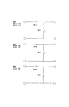
ここで、2段スイッチの構造について図3を用いて説明する。本実施例に用いる2段スイッチは、1段目を押してさらに押し込むことで2段目のスイッチがオンになる構造となっている。一般的にスイッチの操作感は、操作者がスイッチのキートップを押し込んでスイッチ内部回路がオン(オフ)となるための作動力と内部回路がオン(オフ)となるために必要な押し込み距離である移動量で支配されていて、この両方を座標入力装置として適切な値に設定することで操作性のよい座標入力装置を構成することが可能となる。
【0028】
図3は、本実施例で用いる2段スイッチの内部回路を示している。図中、状態1は、スイッチ23とスイッチ24の両方がオフの状態を示している。そして、1段目であるスイッチ23を押すと状態2に示すようにスイッチ23の接点がオンになる。状態2の状態からさらに押し込むことによってスイッチ24の接点がオンになり、状態3に示すようなスイッチ状態となる。すなわち、状態3ではスイッチ23とスイッチ24の両方がオンになる。したがって、この図からもわかるように2段スイッチは1段目と2段目が連動しており、1段目が押されていて、すなわちオン状態でなければ、2段目がオンとなる状態は有り得ず、言い換えれば、2段目のスイッチがオンのときは、必ず1段目のスイッチがオンの状態である。
【0029】
図2の25は回転スイッチで、ペン先22が指示した点を直接座標として出力する絶対座標方式と前回の座標との差分を出力する相対座標方式を操作者が入力用途によって適宜切り替えることができるような構成となっている。スイッチ25を回転させてAの表示を切り欠き26と合わせることでモードA(絶対座標出力モード)になり、またはBの表示を切り欠き26と合わせることでモードB(相対座標出力モード)になる。
【0030】
ここで、各モードについて説明を加える。まず、モードAの絶対座標方式は、画面に直接ペン先22をタッチして入力する場合に特に有効で、アイコンなどの表示されている内容に対して、操作者はダイレクトに指示操作ができるため非常に応答性に優れるものである。一方で、モードBの相対座標方式は、画面から離れて入力(遠隔操作)する場合に特に有効で、コンピュータを操作するマウスと同じように前回の座標に対する差分値でカーソルの移動量を算出するので、画面に表示されている現状のカーソル位置を操作者が確認し、その位置から所望の位置までカーソルを移動させたり、アプリケーションによっては、カーソルが移動する軌跡として図形や文字等を描画したりすることができる。
【0031】
それぞれのモードには、以下のような利点がある。まず、絶対座標方式は、画面と座標入力装置が一体に構成された入出力一体型の装置では、画面に対してダイレクトに操作が可能であるため直感的な入力が可能である。したがって、カーソルをクリックしたいところに何度も移動(ドラッグ)させないでも、ペン先を指示したい点に示せば瞬時に操作が可能である。また、相対座標方式は、マウスと同じ座標出力方式なので、同じイメージで操作者が操作を習得するのが比較的容易である。さらに、特に大画面のときには、ペンが届かない位置への入力が可能で、ペンの移動範囲が狭くても入力が可能であるため手を大きく動かさなくてすむことがあげられる。そしてさらに、表示されているカーソルに対して離れた場所での座標の入力が可能なので、表示されている内容を手や体で隠さないで入力することが可能である。
【0032】
上述のように、各モードはそれぞれ主となる使用用途が存在するが、本願の座標入力装置は汎用性のある装置であるため操作者の用途は多岐にわたるものと考えられる。ゆえに、上記の各モードの利点を生かして、操作者は随時モードを切り替えられる構成とした。
【0033】
したがって、本実施例のペン21に配置する回転スイッチ25は、座標の入力中は操作者の任意のタイミングで変更が可能で、画面に表示されているメニューアイコンを操作して変更するなどの操作が不要となる。
【0034】
なお、ペン21に配置されている各スイッチの情報は、赤外線や電波で本体に送信してもよいし、発振の間隔をスイッチの動作ごとに可変させることによって、本体側で検出してもよい。
【0035】
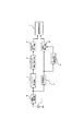
図4は、超音波方式の座標入力装置を構成したブロック図である。
【0036】
図中、301は入力ペン202の内部構成を図示している。302は、不図示のバッテリで動作する303の発振子を駆動する駆動回路である。この駆動回路302は、発振子303を所定のタイミングで駆動するように制御している。そして、発振子303から発振された超音波信号は、座標入力装置本体203の内部回路304のうち、超音波センサ305で検出される。検出された超音波信号は、波形処理回路306で所定のレベルまで増幅されて、検出タイミング信号としてCPU307に入力される。こうして、複数の超音波センサで検出されたタイミング信号が揃ったらCPU307は、時間情報から距離情報に変換して、さらに三角測量の原理で入力ペン202の座標位置を算出する。なお、この座標計算は、ROMに格納されている座標算出プログラム307をCPU307が呼び出すことによって実行される。そして、算出された座標データは、メモリ310に格納される。さらに、座標データは、逐次無線インターフェース311によって、外部のコンピュータに転送される。
【0037】
なお、本実施形態のシステム構成は、上述した構成以外にも種々の構成を採用することができる。例えば、入力具はペン状に限定されるものではなく、いわゆる指示棒状やリモコンの形状であってもよい。また、座標入力の方式は、超音波方式に限らず、赤外線利用方式、抵抗膜方式、電磁誘導方式、或いは、静電結合方式等も採用することができる。
【0038】
但し、本実施例のようなXYZ軸の3次元の座標を算出することが可能な座標入力装置ではなく2次元の座標を算出する座標入力装置の場合においては、例えば赤外線の反射光を用いることで距離を測定できる機能を付加するなどして、画面と入力装置の間の距離を算出できる機能を別に有するならば、本願の発明が有効であることは言うまでもない。
【0039】
また、表示装置は、リアプロジェクション装置に限定されず、フロントプロジェクタ、液晶ディスプレイ、プラズマディスプレイ等、コンピュータの情報を表示することができるものであれば本願の発明が有効であることは言うまでもない。
【0040】
<座標入力装置の動作に関する説明(図5)>
以下、遠隔操作の場合(スイッチ23およびスイッチ24の操作による入力)の入力例をあげて、本実施例における座標入力装置の入力ペンの入力方法について説明する。
【0041】
図5は、表示装置の画面上にカーソルが表示されているときの入力例を示している。今、操作者が、図5の1に示した点Aから点Bまで線を描画したいとき、ペンのスイッチの動作とペンから出力される超音波が発振あるいは停止のいずれかの状態にあるかと座標入力装置の座標出力モードに関して図5を用いて説明する。
【0042】
なお、図5の入力例は、ペンの位置とは関係なく画面に表示されている内容を示したものであり、絶対座標モードでも相対座標モードでも同様である。
【0043】
まず、カーソル401が画面上に表示されていて、点Aから点Bまで線を描画したいとき(描画は、マウスの左クリックを押しながらカーソルを移動させたのと同様に、座標情報とスイッチ情報がコンピュータに送信されることによって描かれる。)、図5において、1の状態はカーソルが画面上に表示されているのみで、ペンのスイッチはいずれも押されていない(図3においてスイッチ23および24がオフの状態)。
【0044】
次に2の状態では、描画を開始したい点Aにカーソルを移動させる。すなわち、スイッチ23をオンにして、超音波を発振するモードにし、カーソルを点Aに移動させる。
【0045】
次に3の状態では、スイッチ23および24をオンにして点Aから点Bまでカーソルを移動させる動作をする。すなわち、この状態は描画されている状態であり、画面上には、カーソルの軌跡が表示される。
【0046】
そして、4の状態では、点Bまで軌跡が表示されてカーソルが移動したならば、スイッチ24をオフ(手をはなす)にする。以上のようにして、座標情報とスイッチ情報を入力することによって、マウスの如きにコンピュータを操作することができる。
【0047】
なお、1および4の状態では、スイッチ23がオンでスイッチ24がオフの状態でもよく、この場合、連続的にカーソルを移動させることができるため、早い入力が必要なときには有効である。
【0048】
<座標入力装置の詳細な構成の説明>
上述した動作をする座標入力装置の構成をより詳細に説明する。
【0049】
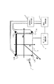
図6は本実施例に於ける3次元(空間)座標計測可能な座標入力装置の概略構成を示すものである。図中4は筆記具であるところの座標入力ペンであって、操作者による座標入力動作により空中に音波を発生するように構成されている。発生した音波は複数の検出センサ3(本実施例の場合、4個の検出センサ3_Sa〜Sdを使用する)により検出され、後述する方法により信号波形検出回路2で処理された後、演算制御回路1によって、筆記具4の発信源位置(X,Y,Z)を算出するように構成されている。演算制御回路1は装置全体を制御するとともに、得られる座標データを基に、ディスプレイ駆動回路5を介して、ディスプレイ6に表示されているカーソルを移動したり、あるいは筆記等の手書き情報をディスプレイ6に表示、追記できるように構成されている。以上のように、座標入力装置と表示装置を組み合わせることで、あたかも『紙と鉛筆』の様な関係を実現することができるマンマシンインターフェースを提供することが可能となる。
【0050】
以下、図面に基づき、本願発明の詳細を説明する。
【0051】
<座標入力ペンの説明>
まず、図7を用いて座標入力ペン4の構成について、その概略を説明する。座標入力ペン4内に内蔵された音波発生源43は、ペン電源45、およびタイマと発振回路、並びに座標入力ペン4に具備されている複数のスイッチ情報を検知して制御する制御回路等で構成された駆動回路44によって駆動される。音波発生源43は、例えばPVDF(ポリフッ化ビニリデン)などの圧電性素子で構成される。このPVDFはフィルム状で、所定サイズの円環状に構成することで、所望周波数で駆動効率が最大になるようになっている。音波発生源43の駆動信号は、タイマによって発せられる所定の周期で繰り返すパルス信号であって、発振回路により所定のゲインで増幅された後、音波発生源43に印加される。この電気的な駆動信号は音波発生源43によって機械的な振動に変換され、空中にそのエネルーギーが放射されることになる。なお本実施例における座標入力ペン4は、画面に直接タッチして入力するための筆記具であるところのペン先端部を押圧することで動作するペン先スイッチ(SW41)と、画面にタッチしないで入力するための座標入力ペン4の筐体に設けられたペンサイド2段スイッチ(SW42aおよびSW42b)を具備する。これらのスイッチを押すことによって、音波発生源43の駆動が開始される。さらに、回転スイッチ46は、回転させることによって切り欠きに合わせてモードを切り替えるスイッチで、「ModeA」に合わせると絶対座標モード、「ModeB」に合わせると相対座標モード、「AUTO」に合わせると自動モード(自動で絶対座標モードと相対座標モードを切り替えるモード)になる。自動モードの詳細については後述する。
【0052】
各スイッチの信号は、駆動回路44で検出されて各モードに対応した信号を赤外線などで本体側に送信される。
【0053】
<本体検出回路の説明>
さて、所定周期毎(例えば10msec毎、その場合、1秒間あたりに音波を100回放射するので、本座標入力装置の座標出力サンプリングレートは、100回/秒となる)に駆動回路44は、座標入力ペン4内の音波発生源43を駆動させる信号を出力し、空中に音波を放射することになるが、その音波は音源と各検出センサ3_Sa〜Sd迄の距離に各々応じて遅延し、到達、検出されることになる。この検出センサ3_Sa〜Sdは、例えばPZT等の厚み振動を行う圧電振動子で、前面に音響整合層を設けている。この音響整合層は、シリコンゴム等を薄層化したもので、気体との音響インピーダンスの整合をとり、高感度で広帯域特性が得られ、またパルス応答性のよい超音波信号の送受信が可能となっている。
【0054】
この種の座標入力装置は、座標入力ペン4の音波発信源と各検出センサ3間の距離を、音波の既知の音速と、その到達時間の積により各々導出し、各検出センサの位置情報を用いて幾何学的に前述音波発信源の位置情報を得ることを基本としたシステムである。そこで、この音波の到達時間を検出する方法について説明する。
【0055】
<検出方式に関する説明>
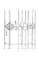
図8は本実施形態における到達時間検出方法を説明するためのタイミングチャートであり、図9はそれを実現するための回路ブロック図である。符号51は駆動回路44で発生した駆動信号であり、駆動信号51を発生するとともにスタート信号を生成する。このスタート信号は例えば座標入力ペン4内に内蔵されている赤外LED等(不図示)を介して、その信号を演算制御回路1に送信し、演算制御回路1内のタイマ12をスタートさせる。一方、空中に放射された音波は、前述音波発生源43と検出センサ3間の距離に応じて遅延し、検出センサ3で検出されることになる。符号53は前置き増幅回路60で所定レベルまで増幅された検出センサ3で検出された検出信号を示す。この信号を絶対値回路及び、低域通過フィルタ等により構成されるエンベロープ検出回路61で処理をし、検出信号のエンベロープ54のみが取り出される。
【0056】
このエンベロープに着目すると、その波形が伝播する音速は群速度Vgであり、このエンベロープの特異な点、例えばエンベロープのピークやエンベロープの変曲点を検出すると、群速度Vgに関わる遅延時間tgが得られる。エンベロープのピーク、あるいは変曲点を検出するエンベロープ特異点検出回路62は微分回路、ゼロクロスコンパレータを用いて容易に検出が可能であり、本実施例では2階微分することによって信号55を形成し、閾値レベル52と信号53で比較されたゲート信号を参照してエンベロープの変曲点を検出する(信号56)。この信号56を用いて前述したスタート信号により動作しているタイマ12をストップさせれば、群速度Vgに関わる群遅延時間Tgを検出することが可能である(なお、図9のブロック図にはこの部分の構成は不図示である。また厳密に言えば、この群遅延時間Tgには、波形処理に関わる回路の遅延分が含まれるが、後述する方法により、その影響は完全に除去される。よって、ここでは説明を簡略化するために、回路遅延時間は無いものとして説明を加える)。従って、音波発生源43と検出センサ3間の距離Lは次式で求めることができる。
【0057】
L=Vg×Tg (1)
一方、より高精度な距離検出を行うための実施形態は、検出信号波形の位相情報より、音波が到達する時間を導出する方法である。その詳細について説明すれば、検出センサ3の出力信号53は、帯域通過フィルタ64により余分な周波数成分を除いた後、Tp信号検出回路66に入力される。Tp信号検出回路66は、ゼロクロスコンパレータ、マルチバイブレータ等で構成され、帯域通過フィルタ64によって出力された信号のゼロクロス点に関わる信号を、所定の閾値レベルと比較するゲート信号発生回路65が生成するゲート信号57と比較し、信号58をまず生成する。その後に、前述した群遅延時間Tgを検出する信号56をゲート信号(ゲート信号発生回路63が生成)として参照し、前述ゲート信号56の期間内において、帯域通過フィルター64で出力される信号波形の位相が、例えば負側から正側にクロスする最初のゼロクロス点を出力する信号59を生成する。同様にして、この信号59を用いて前述したスタート信号により動作しているタイマ12をストップさせれば、位相速度Vpに関わる位相延時間Tpを検出することが可能である(厳密にいえば、この群遅延時間Tpには、波形処理に関わる回路の遅延分が含まれるが、後述する方法により、その影響は完全に除去される。よって、ここでは説明を簡略化するために、回路遅延時間は無いものとして説明を加える)。従って、音波発生源43と検出センサ3間の距離Lは次式で求めることができる。
【0058】
L=Vp×Tp (2)
さてここで、エンベロープ特異点検出回路62に基づきゲート信号発生回路63で生成するゲート信号を用いる効果について説明する。
【0059】
検出センサ3によって検出される信号レベルは、次の要因によって変動する。
1)音波発生源43、検出センサ3の電気−機械変換効率
2)音波発生源43と検出センサ3間の距離
3)音波が伝播する空中の温度、湿度等の環境変動
4)音波発生源43の音波放射に関する指向性、並びに検出センサ3の感度指向性
項目1は、部品公差により発生する要因であり、装置を大量生産する場合には十分な留意が必要である。また項目2は音波の減衰に関する項目であり、音波発生源43と検出センサ3間の距離が大きくなるにつれて、空気中を伝播する音波の信号レベルは指数関数的に減衰することが一般的によく知られている他、その減衰定数も項目3による環境で変化する。
【0060】
<演算制御回路1の説明>
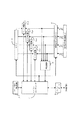
図10は本実施例の演算制御回路1の概略構成を示すブロック図で、各構成要素及びその動作概略を以下に説明する。図中11は演算制御回路1及び本座標入力装置全体を制御するマイクロコンピュータであり、内部カウンタ、操作手順を記憶したROM、そして計算等に使用するRAM、定数等を記憶する不揮発性メモリ等によって構成されている。前述した通り、駆動回路44により座標入力ペン4内の音波発生源43の駆動タイミングと同期したスタート信号が、座標入力ペン4に内蔵された赤外LED等(不図示)により光信号として放射され、その信号をスタート信号検出回路17で検波することによって、演算制御回路1内のタイマ12(例えばカウンタなどにより構成されている)をスタートさせる。このように構成することで、座標入力ペン4内の音波発生源43を駆動する駆動タイミングと、演算制御回路1内の例えばタイマとの同期が得られるので、音波発生源43で発生した音波が、音波発生源43から各検出センサ3各々に到達するのに要する時間を測定することが可能となる。
【0061】
信号波形検出回路2より出力される各振動センサ3_Sa〜3_Sdよりの振動到達タイミング信号(第1実施例における符号59の信号)は、検出信号入力ポート13を介してラッチ回路15_a〜15_dに各々入力される。ラッチ回路15_a〜15_dの各々は、対応するセンサよりのタイミング信号を受信すると、その時のタイマ12の計時値をラッチする。この様にして座標検出に必要な全ての検出信号の受信がなされたことを判定回路14が判定すると、マイクロコンピュータ11にその旨の信号を出力する。マイクロコンピュータ11がこの判定回路14からの信号を受信すると、ラッチ回路15_a〜15_dから各々の振動センサまでの振動到達時間をラッチ回路より読み取り、所定の計算を行なって、座標入力ペン4の座標位置を算出する。その結果を、I/Oポート16を介してディスプレイ駆動回路5に出力し、ディスプレイ6の対応する位置に、例えばドット等を表示することができる様に構成した。またI/Oポート16を介しインターフェース回路に、座標位置情報を出力することによって、外部機器に座標値を出力することができる様に構成したものである。
【0062】
<第二の実施例>
本願発明の第二の実施形態は、前述のごとく精度良く距離を求める方法について説明するものである。
【0063】
図11、図12を用いて同様に説明すれば、符号71は駆動回路44で発生した駆動信号であり、駆動信号71を発生するとともにスタート信号を生成する。このスタート信号は例えば座標入力ペン4内に内蔵されている赤外LED等(不図示)を介して、その信号を演算制御回路1に送信し、演算制御回路1内のタイマ12をスタートさせる。一方、空中に放射された音波は、前述音波発生源43と検出センサ3間の距離に応じて遅延し、検出センサ3で検出されることになる。符号73は前置き増幅回路80で所定レベルまで増幅された検出センサ3で検出された検出信号を示す。この信号を絶対値回路及び、低域通過フィルタ等により構成されるエンベロープ検出回路81で処理をし、検出信号のエンベロープ74のみが取り出される。
【0064】
このエンベロープ74に着目すると、その波形が伝播する音速は群速度Vgであり、このエンベロープの特異な点、例えばエンベロープのピークやエンベロープの変曲点を検出すると、群速度Vgに関わる遅延時間tgが得られる。エンベロープのピーク、あるいは変曲点を検出するエンベロープ特異点検出回路82は微分回路、ゼロクロスコンパレータを用いて容易に検出が可能であり、本実施例では2階微分することによって信号75を形成し、閾値レベル72と信号73で比較されたゲート信号を参照してエンベロープの変曲点を検出する(信号76)。この信号76を用いて前述したスタート信号により動作しているタイマ12をストップさせれば、群速度Vgに関わる群遅延時間Tgを検出することが可能である(同様に回路の遅延分が含まれるが、説明を簡略化するために、回路遅延時間は無いものとして説明を加える)。従って、音波発生源43と検出センサ3間の距離Lは(1)式で求めることができる。
【0065】
一方、検出センサ3の出力信号73は、帯域通過フィルタ84により余分な周波数成分を除いた後、Tp信号検出回路86に入力される。Tp信号検出回路86は、ゼロクロスコンパレータ、マルチバイブレータ等で構成され、帯域通過フィルタ84によって出力された信号のゼロクロス点に関わる信号を、所定の閾値レベルと比較するゲート信号発生回路85が生成するゲート信号77と比較し、信号78をまず生成した後、帯域通過フィルター84で出力される信号波形の位相が、例えば負側から正側にクロスする最初のゼロクロス点を出力する信号79を生成する。同様にして、この信号79を用いて前述したスタート信号により動作しているタイマ12をストップさせれば、位相速度Vpに関わる位相延時間Tp_2を検出することが可能である。しかしながらこの信号は、前述したとおり信号73の信号レベルによって変化する(例えば信号レベルがより低下した場合には、固定閾値で比較されるゲート信号のために、ゲート信号発生位置が変化し、例えば信号78′となる)。しかしながらこの位相遅延時間Tp_2と前述した第1実施例で求められたTp信号の差分は、検出信号波形73の位相周期の整数倍であって、必ず以下の関係が成立する。
【0066】
Tp=Tp_2+n×T (3)
ここでnは整数、Tは検出信号波形の位相周期であり、既知の値である。式(3)を式(2)に代入し、式(1)を用いれば
n=Int[(Vg×Tg−Vp×Tp_2)/λp+0.5] (4)
ここでλpは音波の波長であって、位相速度Vpと周期Tの積に等しい。よって整数nが既知となり、式(2)、式(3)を用いて距離Lの導出が高精度に可能となる(上述の説明において、第3図信号56と信号58の時間差Δ、および図7に示される信号76と信号78の時間差Δが存在するが、空中を伝播する音波の群速度Vgと位相速度Vpは等しく、この時間差Δは固定量となる。従って、回路遅延と同様に後述する方法で、その影響は完全に除去されるので、ここではΔ=0として説明している)。
【0067】
第一の実施例に比べ、第二の実施例は位相遅延時間の検出点が検出信号波形53、73のより先頭部分に位置することにあり、この様な構成とすることで、反射波による影響をより軽微なものにすることができる。よって本願の実施例においては、群遅延時間Tgの検出点を特定するために、エンベロープのピーク(1階微分)でなく、より前方に位置する変曲点(2階微分)を検出点としているし、さらには第一の実施例よりも第二の実施例のほうが位相遅延時間Tpの検出点が、検出信号波形のより先頭部に位置しているので、前述した反射波の影響を受けにくく、より高精度に座標算出を可能とする優れた構成であると言える。さらに第二実施例の群遅延時間Tgは、先に述べた演算方法により整数nを算出するため(式4)にのみ使用され、しかも式(4)で演算上、整数化(四捨五入相当)を実行することになるので、例えば反射波の影響による群遅延時間tgの誤差が検波する信号波形の位相の半周期以内(長さに換算して、半波長以内)であれば、結果に影響することが無い。従って、第二実施例は、より反射波の影響を除去することができる優れた構成であると言える。
【0068】
しかしながら、群遅延時間Tg、位相遅延時間Tpの両者を検出しなければならない第二の実施例に比べ、第一の実施例は位相遅延時間Tpのみでの検出が可能であり、コスト的にはより有利な構成となっている。従って、どちらの実施形態を採用するかは、目的とする製品形態の仕様によって選択することになる。
【0069】
以上述べた実施例において、検出された時間には、音波発生源43と各検出センサ3まで音波が到達する時間に加えて、回路等による電気的な処理時間も含まれる。従って、ここでは、音波が伝播する時間以外に余分に計測される時間を除去する方法について説明する。前記ラッチ回路によってラッチされた群遅延時間Tg、もしくは位相遅延時間Tpには、各々群回路遅延時間etg、位相回路遅延時間etpを含む。この回路遅延時間は、時間計測毎に同一の値を必ず含む。そこで、ある計測回路によって、音波発生源43と検出センサ3間を伝播する際に計測された時間をt*、その計測回路における回路遅延時間をe、実際に音波が音波発生源43と検出センサ3間を伝播したのに要した時間をtとすれば、
t*=t+e (5)
一方、音波発生源43と検出センサ3間の距離が既知の距離Liniにおける時間計測値をtini *とし、その計測回路における回路遅延時間をe、実際に音波が伝播した時間をtiniとすれば
tini *=tini+e (6)
よって
t*−tini *=t−tini (7)
今、音波の音速をVとすれば、
V×(t*−tini *)=V×(t−tini)=V×t−Lini (8)
よって求めるべき任意の音波発生源43と検出センサ3間の距離Lは
L=V×t=V×(t*−tini *)+Lini (9)
上記、既知の距離Lini、及びその距離における時間計測値tini *(第一実施例においては群遅延時間Tgini *、位相遅延時間Tpini *、第2実施例においては、その両者)を、出荷時等に不揮発性メモリ等に記憶することによって、任意の距離における音波発生源43と検出センサ3間の距離を精度良く算出することが可能となる。また前述したように、図8信号56と信号58の時間差Δ、および図11に示される信号76と信号78の時間差Δについても固定量(一般に空中を伝播する音波の群速度Vgと位相速度Vpは等しい)であるので、上記の方法によりその影響を除去することが可能である。
【0070】
<座標算出式の説明>
さて今、図13の様な座標系に検出センサ3_Sa〜3_Sdが配置された時、音波発生源43の位置座標(x、y、z)を求める方法について説明する。上記の方法により正確に求められた振動発生源43と各検出センサ3までの距離を各々La〜Ld、X方向の検出センサ間距離をXs−s、Y方向の検出センサ間距離をYs−sとすれば
【外1】

同様にして
【外2】
以上示したように少なくとも3個の振動発生源43と検出センサ3までの距離が測定できれば、容易に音波発生源43の位置(空間)座標を求めることが可能となる。本願発明の実施例では、検出センサを4個用いており、例えば、距離が最も遠い情報を使わず(この場合、検出センサ3で出力される信号は、距離が遠いために信号レベルが最も小さくなっている)、残り3個の距離情報のみで、座標を算出することで、信頼性の高い座標算出を可能としている。また、この距離が遠いセンサの情報を活用することで、出力された座標値の信頼性が高いものか判定することも可能である。具体的方法としては、例えば、距離情報La、Lb、Lcで算出された座標値と、距離情報Lb、Lc、Ldで算出された座標値は同一の値を出力するはずであり(距離情報の組み合わせを変更して演算する)、両者が一致しない場合には、いずれかの距離情報が不正、つまり誤検出したことになるので、その場合には、座標値を出力しない、と言った信頼性を向上させる構成も実施可能となる。
【0073】
<空間座標算出モードの説明>
次に本願発明の様な空間座標を算出することが可能な座標入力装置の動作モードについて説明する。
【0074】
本願発明の座標入力ペンは、外観図を図7に示すように、ペン先SW41、及び2段スイッチであるペンサイドSW42a,SW42b、さらに座標出力モードを切り替える回転スイッチ46を具備してなり、各SWの動作モードについて表1から表3、図14を用いて説明を加える。また、座標入力ペンの動作モードに対応した検出回路側(本体側)の動作モードについて表1から表3、図15を用いて説明をする。
【0075】
図7の駆動回路44内のメモリには、図14に示す動作プログラムが内蔵されていて、同じく駆動回路44内の制御回路は、SW41およびSW42a,SW42b,SW46の動作にしたがって以下のように動作する。
【0076】
まず、ステップS102で、SW46の状態としてどのモードがセットされているかを検知して駆動回路44内のメモリにセットされる。次に、操作者が、座標入力ペン4を握って座標入力面(表示装置のスクリーン面にXY平面(z=0)が設定されている)を押圧する場合は、ペン先SW41が動作する。このとき、ステップS103でSW41=ONなのでステップS104に進む。
【0077】
ステップS104では、SW46の状態をメモリから読み込みModeがA(絶対座標モード)かどうかを判定する。Mode=Aの場合は、ステップS107で駆動間隔Tをセットする。ステップS107では、T=T1(例えば、100回/秒)に設定して、ステップS108で音波発生源43を駆動して音波が空中に放射されるように動作する。すなわち、表1において動作モードはペン入力モード(Mode=1)になる。ステップS104でModeがAではない場合は、ステップS105でModeがB(相対座標モード)かどうかを判定する。Mode=Bの場合は、ステップS106で駆動間隔Tをセットする。ステップS106では、T=T2(例えば、50回/秒)に設定して、ステップS108で音波発生源43を駆動して音波が空中に放射されるように動作する。すなわち、表2において動作モードはペン入力モード(Mode=3)になる。ステップS105でModeがBではない場合は、Mode=AUTO(自動モード)であると判定して、ステップS107では、T=T1(例えば、100回/秒)に設定して、ステップS108で音波発生源43を駆動して音波が空中に放射されるように動作する。すなわち、表3において動作モードはペン入力モード(Mode=1)になる。
【0078】
さらに、ステップS109でSW41の状態を検知する動作を実行して、SW41がONの状態であるならば、操作者が筆記動作を続けているとみなして、ステップS108の音波発生源43を駆動する動作を繰り返す。ステップS109でSW41がOFFのとき、すなわち、操作者が座標入力面から座標入力ペン4を離したときは、ステップS110で所定の時間(例えば10秒)だけタイマ(Timer)をセットする。次に、ステップS111では、SW46の状態をメモリから読み込みModeがA(絶対座標モード)どうかを判定する。Mode=Aの場合は、ステップS114で駆動間隔Tをセットする。ステップS114では、T=T11(例えば、40回/秒)に設定して、ステップS115で音波発生源43を駆動して音波が空中に放射されるように動作する。すなわち、表1において動作モードは近接入力モード1(Mode=2)になる。ステップS111でModeがAではない場合は、ステップS112でModeがB(相対座標モード)かどうかを判定する。Mode=Bの場合は、ステップS113で駆動間隔Tをセットする。ステップS113では、T=T21(例えば、30回/秒)に設定して、ステップS115で音波発生源43を駆動して音波が空中に放射されるように動作する。すなわち、表2において動作モードは近接入力モード(Mode=4)になる。ステップS112でModeがBではない場合は、Mode=AUTO(自動モード)であると判定して、ステップS114では、T=T11(例えば、40回/秒)に設定して、ステップS115で音波発生源43を駆動して音波が空中に放射されるように動作する。すなわち、表3において動作モードは近接入力モード(Mode=2)になる。
【0079】
そして、ステップS116でSW41の状態を検知する動作を実行して、SW41がOFFの状態であるならば、ステップS115で音波発生源43を駆動するように動作し、ステップS117でタイマがゼロ(Timer=0)になるまでこの動作を繰り返す。途中ステップS116でSW41の状態がONになったときは、操作者が筆記動作を再開したとみなして、ステップS103に戻る。
【0080】
次に本実施例では、図7に示すSW42aを押すことによってカーソルを移動させて、さらにSW42bを押し込むことでアイコンのクリックや描画の動作を実現する。ステップS103でSW41がOFFの場合は、ステップS118でSW42aの状態を判定する。ステップS118でSW42aがONのとき、すなわち操作者が、座標入力面から離れて操作する場合には、次にステップS119でSW42bの状態を検知する動作をさせる。ステップS119でSW42bがOFFのときは、さらにステップS120でSW41の状態を判定する。ステップS120でSW41がONの場合は、ステップS104を実行する。ステップS120でSW41がOFFの場合は、ステップS121で、SW46の状態をメモリから読み込みModeがA(絶対座標モード)どうかを判定する。Mode=Aの場合は、ステップS124で駆動間隔Tをセットする。ステップS124では、T=T11(例えば、40回/秒)に設定して、ステップS125で音波発生源43を駆動して音波が空中に放射されるように動作する。すなわち、表1において動作モードは遠隔入力モード(Mode=2)になる。ステップS121でModeがAではない場合は、ステップS122でModeがB(相対座標モード)かどうかを判定する。Mode=Bの場合は、ステップS123で駆動間隔Tをセットする。ステップS123では、T=T21(例えば、30回/秒)に設定して、ステップS125で音波発生源43を駆動して音波が空中に放射されるように動作する。すなわち、表2において動作モードは遠隔入力モード(Mode=4)になる。ステップS122でModeがBではない場合は、Mode=AUTO(自動モード)であると判定して、ステップS124では、T=T11(例えば、40回/秒)に設定して、ステップS125で音波発生源43を駆動して音波が空中に放射されるように動作する。すなわち、表3において動作モードは遠隔入力モード(Mode=3)になる。
【0081】
一方、ステップS119でSW42bがONの場合は、ステップS126では、SW46の状態をメモリから読み込みModeがA(絶対座標モード)かどうかを判定する。Mode=Aの場合は、ステップS129で駆動間隔Tをセットする。ステップS129では、T=T1(例えば、100回/秒)に設定して、ステップS130で音波発生源43を駆動して音波が空中に放射されるように動作する。すなわち、表1において動作モードは遠隔入力モード(Mode=1)になる。ステップS126でModeがAではない場合は、ステップS127でModeがB(相対座標モード)かどうかを判定する。Mode=Bの場合は、ステップS128で駆動間隔Tをセットする。ステップS128では、T=T2(例えば、50回/秒)に設定して、ステップS130で音波発生源43を駆動して音波が空中に放射されるように動作する。すなわち、表2において動作モードは遠隔入力モード(Mode=3)になる。ステップS127でModeがBではない場合は、Mode=AUTO(自動モード)であると判定して、ステップS129では、T=T1(例えば、100回/秒)に設定して、ステップS130で音波発生源43を駆動して音波が空中に放射されるように動作する。すなわち、表3において動作モードは遠隔入力モード(Mode=4)になる。
そして、再びステップS131でSW42bの状態を検知する動作をし、SW42bがONのときには、入力が継続しているとみなして、ステップS130で音波発生源43を駆動する動作を繰り返す。ステップS131でSW42bがOFFのときには、ステップS102に戻り以上の動作を繰り返し実行する。
【0082】
なお、通常の動作としては、Mode=AUTOでの入力が多いと考えられる。したがって、ペン入力モード(Mode=1)、近接入力モード(Mode=2)、遠隔入力モード2(Mode=4)、遠隔入力モード1(Mode=3)の順番で操作者が高速に入力をすることを考慮すると、各モード(Mode=1〜4)における駆動間隔Tは、駆動間隔:T1<T11<T21<T2のように設定することで効率よく本願の座標入力装置を構成することができる。すなわち、座標入力ペン4の消費電力を抑えることができるので電池寿命を延ばすことができるという効果がある。
【0083】
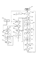
次に、検出回路側(本体側)での動作について図15を用いて説明する。図15において、ステップS1310の待機状態から、ステップS132で、検出センサ3が信号を検出したと判断されたならば、上述したとおり、座標入力ペン4の位置座標X,Y,Zを算出する。次にステップS134で前回のサンプリングのときの座標と差分値を計算してΔX,ΔYを算出しておく。次に、ステップS134で駆動間隔Tを判定する。ここで、T=T1のときは、ステップS136で座標入力ペン4から出力されたSW26の状態を示す信号が、Mode=AUTOかどうかを検出する。ここで、検出されたModeがAUTO以外のときは、ステップS142でMode=1に設定してペン入力モードの動作をさせる。また、ステップS136でMode=AUTOのときは、ステップS137でステップS133で算出したZ座標の大きさを判断する。本実施例では、Z座標が400mmを閾値として比較される。Z座標が400mm以上のときは、ステップS144でMode=3に設定して、遠隔入力モード1の動作をさせる。Z座標が400mmより小さいときは、ステップS142でMode=1に設定して、ペン入力モードの動作をさせる。
【0084】
ステップS135で駆動間隔Tを判定した結果がT=T1以外の場合は、さらにステップS138で駆動間隔Tを判定する。ここで、T=T11のときは、ステップS139で座標入力ペン4から出力されたSW26の状態を示す信号が、Mode=AUTOかどうかを検出する。ここで、検出されたModeがAUTO以外のときは、ステップS143でMode=2に設定して近接入力モードの動作をさせる。また、ステップS139でMode=AUTOのときは、ステップS140でステップS133で算出したZ座標の大きさを判断する。Z座標が400mm以上のときは、ステップS145でMode=4に設定して、遠隔入力モード2の動作をさせる。Z座標が400mmより小さいときは、ステップS143でMode=2に設定して、近接入力モードの動作をさせる。
【0085】
また、ステップS138でT=T11と判断されない場合は、ステップS141に進み前回のサンプリングに計算した座標値X,Yとの差分値(相対座標)ΔX,ΔYの出力方式を決定するために、ステップS141で駆動間隔Tを判定する。ここで、T=T2のときは、ステップS144でMode=3に設定して遠隔入力モード1の動作をさせる。ステップS141でT=T2以外の駆動間隔と判断されたときは、ステップS145でMode=4に設定して遠隔入力モード2の動作をさせる。
【0086】
以上の動作において、Mode=1およびMode=2では、ステップS146で絶対座標X,Yを出力する。また、Mode=3およびMode=4では、ステップS147で相対座標ΔX,ΔYを出力する。
【0087】
ここで、各モードの動作について説明する。まず、ペン先SW41がオン状態の場合はペン入力モード(Mode=1)は、算出される座標値は絶対座標値(X,Y,0)であって、その値を直接外部装置に出力することで、操作者は筆記動作が可能となる。
【0088】
一方、ペン先SW41がオフ状態の場合は、少なくとも操作者によるXY平面内(Z=0)での座標入力が行われていない状態を意味するが、その場合であっても、画面上に表示されているカーソルを移動する等の動作を行えることが好ましい。そのため、ペン先SW41がオン状態からオフ状態に遷移したときには一定時間、ペン先SW41を座標入力面に押しつけなくても(ペンSW41がオン状態でなくても)座標の入力が可能な近接入力モード(Mode=2)を有している。
【0089】
さらに、本願の座標入力装置は、座標入力面(XY平面)から離れて入力する(Z>0であることを示す)ことが可能であり、SW42aが押されることで遠隔入力1モード(Mode=3)、また、SW42a,SW42bが同時に押されることで、遠隔入力2モード(Mode=4)に設定されて、座標入力ペンの動きによってカーソルを移動し、その移動状態を記録(筆跡)として残すことが可能となっている。
【0090】
また、本願の座標入力装置の座標入力ペンは、各モードにおける座標出力の方式を切り替えることができるSW46を有しているので、操作者は、通常の使用ではAUTOモードにすることで画面と入力点の距離によって、絶対座標と相対座標を適宜自動的に切り替えていても、用途によって絶対座標あるいは相対座標に固定したい場合には、座標入力ペンのスイッチを切り替えるだけで容易に座標出力形式を固定のモードに変更することが可能である。
【0091】
<第三の実施例>
本願発明の第三の実施形態は、先に説明した第一実施例および第二実施例における座標入力ペン4に具備されている2段スイッチであるペンサイドスイッチSW42a,SW42bが、振動発生源43の駆動を制御するのみではなく、第一実施例および第二実施例においてはSW46の機能であった座標の出力形式のモードを変更するスイッチをも兼ねる構成とした場合ついて説明する。
【0092】
本実施例は、座標入力ペン4に具備されている2段スイッチであるペンサイドスイッチSW42a,SW42bについて、1段目がオンになる時間から2段目がオンになる時間までを計測すること、および2段目がオンの時間を計測するように構成にしたことが特徴である。
【0093】
上記時間は、座標入力ペン4に内蔵されている駆動回路のCPUにて各スイッチから出力されるオン・オフで極性が切り替わるパルス信号が入力されていて、該パルス信号の例えばオンになったときの立上りエッジから立上りエッジまでの時間をクロックパルスでカウントすることによって計測する。そして、得られた時間について、あらかじめメモリされている所定の閾値と比較することによって、モードの切り替え動作を実行する。
【0094】
図16から図18は、上記動作を示したフローチャートで、図16は、座標の出力形式は本体側で得られた座標によって、自動的に決定される自動モードであり、メインのフローチャートである。図17は、絶対座標モードが実行された場合のフローチャートである。また、図18は、相対座標モードが実行された場合のフローチャートである。
【0095】
図16において、各モードを示すフラグであるiの初期値としてi=0がセットされる。そして、ペンサイドスイッチSW42a,SW42bが押された場合、すなわち2段目までオンになった場合は、ステップS166で1段目がオンになる時間から2段目がオンになる時間までを計測し(Δt)、所定の閾値kと比較される。さらに、2段目が押され続けている時間t2onを所定値jと比較する。両者の比較された結果が、Δt≦kかつt2on≧jと判定された場合はモードを変更するために、ステップS170に進みフラグをi=1にセットしてステップS171で絶対座標モードジャンプする。
【0096】
図17では、図16を上記で説明したのと同様に、モードを切り替える操作をした場合は、ステップS198でΔt≦kかつt2on≧jと判定されるので、ステップS202でフラグをi=2にセットしてステップS203で相対座標モードジャンプする。
【0097】
同様に図18の相対座標モードでは、モードを切り替える操作をした場合は、ステップS228でΔt≦kかつt2on≧jと判定されるので、ステップS232でメインモード(自動モード)へジャンプする。
【0098】
以上のように、SW42a,SW42bを所定のタイミングで押すたびに、絶対座標モード→相対座標モード→自動モードとループして座標出力モードを変更することが可能であり、第一実施例および第二実施例と比較して、部品コストを削減させることができるという効果がある。
【0099】
【表1】
【表2】
【表3】
【発明の効果】
以上説明したように、本発明によれば、座標入力面に対して所望の位置を指示して座標を入力する座標入力装置であって、位置を指示する位置指示手段と、該位置指示手段によって指示された座標を算出する座標算出手段と、前記座標算出手段が算出する座標を出力する座標出力手段と、前記座標出力手段が出力する座標を絶対座標あるいは相対座標に切替える座標切替手段を前記位置指示手段が有するので、座標の入力を操作者が所望する入力方式を容易に選択できる操作性に優れた座標入力装置を提供することができる。
【図面の簡単な説明】
【図1】第1実施例に係る座標入力装置を利用したシステムの一例を示す図。
【図2】第1実施例に係る座標入力ペンの模式図。
【図3】第1実施例に係る座標入力ペンに配置された2段スイッチの回路図。
【図4】第1実施例に係る座標入力装置の方式の一例を説明する図。
【図5】第1実施例に係る座標入力装置の入力方法の一例を説明する図。
【図6】第1実施例に係る座標入力装置の概略構成図。
【図7】第1実施例に係る座標入力装置の座標入力ペンを説明する図。
【図8】第1実施例に係る信号処理のタイミングチャート。
【図9】第1実施例に係る信号処理のブロック図。
【図10】演算制御回路1のブロック図。
【図11】第2実施例に係る信号処理のタイミングチャート。
【図12】第2実施例に係る信号処理のブロック図。
【図13】座標系を説明する説明図。
【図14】第2実施例に係る座標入力ペンの動作を説明するフローチャート。
【図15】第2実施例に係る検出回路側の動作を説明するフローチャート。
【図16】第3実施例に係る座標入力ペンの動作を説明するフローチャート。
【図17】第3実施例に係る座標入力ペンの動作を説明するフローチャート。
【図18】第3実施例に係る座標入力ペンの動作を説明するフローチャート。
【符号の説明】
1 演算制御回路
2 信号波形検出回路
3 検出センサ
4 座標入力ペン
6 表示ディスプレイ
41 ペン先SW
42a ペンサイドSW
42b ペンサイドSW
43 音波発生源[0001]
TECHNICAL FIELD OF THE INVENTION
The present invention relates to a coordinate input device that can constitute an input / output integrated device when used in combination with a display system. In more detail, by inputting coordinates directly on the display screen with a pointing device, or by inputting coordinates from a distance from the screen, you can control an externally connected computer or write characters and graphics The present invention relates to a coordinate input device used for (1).
[0002]
[Prior art]
2. Description of the Related Art Conventionally, a coordinate input device capable of inputting coordinates is disposed on a display surface of a display device such as a CRT display, a liquid crystal display (LCD), or a projector, so that pointing or handwriting performed by an operator can be performed. 2. Description of the Related Art Devices that can be displayed on a display and realize a relationship like paper and a pencil are known. Examples of the coordinate input device include a resistive film type, an electrostatic type, an ultrasonic type that transmits ultrasonic waves to a coordinate input surface such as glass, an ultrasonic type, a type having a transparent input plate, an optical type, or a type in which sound waves are transmitted in the air. A mechanism for calculating coordinates is placed on the back side of the display device, and a transparent protective plate is placed on the front of the display device, such as a method of detecting the position by radiating, or an electromagnetic induction (electromagnetic transfer) method. In some cases, an information device integrated with an input / output is configured.
[0003]
Such devices began with small electronic organizers having portability, and with the increase in size of display devices such as pen input computers, information devices of relatively large size have come to be seen. Then, in combination with a large display device such as a front projector, a rear projector, or a PDP, it has begun to be used for a presentation device, a TV conference system, and the like. The image quality and cost of these large liquid crystal displays and PDP displays are still being improved, and with the digitization of satellite broadcasts and the like, the specification of televisions is entering a transitional state.
[0004]
In addition, these large-sized display devices are replaced with, for example, whiteboards or electronic blackboards used in offices. It is starting to be used In this case, the information displayed on the display is controlled by directly touching the screen to update the display information by the operator or the attendees, such as a whiteboard. Is configured to be able to switch the display content.
[0005]
[Problems to be solved by the invention]
However, when this type of large-sized integrated input / output system is considered, there are the following problems. In other words, taking into account meetings with a large number of participants or using the environment via a network, the operator not only controls the PC by directly touching the screen, but also allows the questioner to remotely control the Therefore, it can be said that it is a preferable embodiment that the screen can be operated or information can be extracted from the network as needed on the spot.
[0006]
Conventionally, this type of device is an absolute coordinate system that directly outputs a point to be pointed when the device is operated by directly touching a pen tip on a screen. Since the operator can directly perform the instruction operation, the accessibility is very high.
[0007]
On the other hand, when performing input (remote operation) away from the screen, a relative coordinate system device that calculates the amount of movement of the cursor using a difference value with respect to the previous coordinate in the same manner as a mouse operating a computer has been mainstream. . Therefore, the operator confirms the current cursor position displayed on the screen and moves the cursor from that position to a desired position, or draws a figure, character, or the like as a locus along which the cursor moves depending on the application. it can.
[0008]
However, it has been difficult to configure both of them with the same device and to switch between the two as appropriate.
[0009]
That is, in a series of input operations in this type of device, first, transmission is controlled by a button switch for switching on / off mounted on an input device (for example, a pen type), and the input device is locked by locking the button switch. After the transmission mode is fixed, the operation of moving the cursor to a desired position is performed. Then, an operation of pressing another button switch is performed in order to perform a drawing operation or an icon click operation at the moved cursor position. Then, the operator unlocks the button switch for controlling the transmission in order to end the operation. Thus, a series of operations for performing the input operation is very complicated.
[0010]
In addition, the operator switches between the absolute coordinate system and the relative coordinate system by mainly selecting the mode from the menu displayed on the display screen and switching the mode. It has to be moved, and the operability is not always good for the operator.
[0011]
The present invention has been made in view of the above-described problems, and provides a coordinate input device which simplifies input of coordinates on a display screen and has excellent operability in which an operator can easily select a desired input method. With the goal.
[0012]
[Means for Solving the Problems]
In order to achieve the above object, an invention according to the present application is a coordinate input device that inputs a coordinate by designating a desired position on a coordinate input surface, and a position instruction unit that designates a position; Coordinate calculating means for calculating coordinates specified by the means, coordinate output means for outputting coordinates calculated by the coordinate calculating means, and coordinate switching means for switching coordinates output by the coordinate output means to absolute coordinates or relative coordinates. The position indicating means is provided.
[0013]
Further, there are provided means for calculating the distance between the position indicating means and the coordinate input surface, and switching means for switching the coordinates output by the coordinate calculating means to absolute coordinates or relative coordinates based on the calculated distance.
[0014]
Further, the position indicating means includes means for transmitting a signal to the coordinate input surface, and further includes switch means for controlling the transmission, and the switch means also functions as the coordinate switching means.
[0015]
Further, ultrasonic input means for inputting a position with respect to a display surface constituting an input surface, a plurality of vibration detecting means provided on a peripheral portion of the display surface, and ultrasonic waves generated from the ultrasonic input means. A coordinate input device that obtains a position of the ultrasonic input unit based on reception timings received by the plurality of vibration detection units; a coordinate calculation unit that calculates coordinates indicated by the ultrasonic input unit; The ultrasonic input means has coordinate output means for outputting coordinates calculated by the means, and coordinate switching means for switching coordinates output by the coordinate output means to absolute coordinates or relative coordinates.
[0016]
Further, there is provided a means for calculating a distance between the ultrasonic input means and the display surface, and a switching means for switching the coordinates output by the coordinate calculating means from the calculated distance to absolute coordinates or relative coordinates.
[0017]
Further, the ultrasonic input means has switch means for controlling driving of ultrasonic waves generated from the ultrasonic input means, and the switch means also serves as the coordinate switching means.
[0018]
Therefore, it is possible to provide a coordinate input device which simplifies input of coordinates on a display screen and has excellent operability in which an operator can easily select a desired input method.
[0019]
BEST MODE FOR CARRYING OUT THE INVENTION
<First embodiment>
Hereinafter, embodiments of the present invention will be described in detail with reference to the drawings.
[0020]
<Description of system configuration (FIG. 1)>
FIG. 1 is a schematic diagram of a system using the coordinate input device of the present invention.
[0021]
This system is an example of a system in which a coordinate input device is built in the rear
[0022]
The coordinate input device calculates the position of the
[0023]
In the figure,
[0024]
Therefore, when the operator is away from the screen at a meeting or the like, the computer can be remotely operated and the displayed contents can be overwritten, so that the device is very effective.
[0025]
<Description of Configuration of Coordinate Input Device (FIGS. 2 to 4)>
As described above, the coordinate input device is a device that, when an arbitrary point on the coordinate input surface is designated using a pen-type input device, detects the coordinates of the input point and outputs the coordinate data to a connected computer. is there. In this embodiment, a case where an ultrasonic coordinate input device is configured as the coordinate input device will be described with reference to FIGS.
[0026]
FIG. 2 shows an input pen of the coordinate input device of the present embodiment. By pressing the pen tip of the coordinate
[0027]
Here, the structure of the two-stage switch will be described with reference to FIG. The two-stage switch used in this embodiment has a structure in which the second-stage switch is turned on when the first stage is pressed and further depressed. Generally, the operational feeling of a switch is determined by the operating force required for an operator to press the key top of the switch to turn on (off) the internal circuit of the switch and the pushing distance required for the internal circuit to be turned on (off). The coordinate input device is controlled by a certain amount of movement, and by setting both of them to appropriate values as the coordinate input device, it is possible to configure a coordinate input device with good operability.
[0028]
FIG. 3 shows an internal circuit of the two-stage switch used in the present embodiment. In the figure,
[0029]
[0030]
Here, each mode will be described. First, the absolute coordinate system in mode A is particularly effective when the
[0031]
Each mode has the following advantages. First, in the absolute coordinate system, in an input / output integrated device in which a screen and a coordinate input device are integrally formed, an intuitive input is possible because an operation can be directly performed on the screen. Therefore, even if the cursor is not moved (dragged) many times to the place where the user wants to click, the operation can be performed instantly by pointing the pen tip to the point to be pointed. Further, since the relative coordinate system is the same coordinate output system as the mouse, it is relatively easy for the operator to learn the operation with the same image. Furthermore, particularly on a large screen, an input can be made to a position where the pen does not reach, and even if the moving range of the pen is narrow, the input is possible, so that the hand does not need to be moved greatly. Further, since the coordinates of the displayed cursor can be input at a position remote from the cursor, the displayed contents can be input without being hidden by the hand or the body.
[0032]
As described above, each mode has a main use purpose. However, since the coordinate input device of the present application is a versatile device, it is considered that the use of the operator is diversified. Therefore, taking advantage of the advantages of each mode described above, the operator can switch the mode at any time.
[0033]
Therefore, the
[0034]
The information of each switch arranged on the
[0035]
FIG. 4 is a block diagram illustrating an ultrasonic coordinate input device.
[0036]
In the figure,
[0037]
Note that the system configuration of the present embodiment can employ various configurations other than the above-described configuration. For example, the input tool is not limited to a pen shape, but may be a so-called pointing stick or a remote controller. The method of inputting coordinates is not limited to the ultrasonic method, but may be an infrared method, a resistive film method, an electromagnetic induction method, an electrostatic coupling method, or the like.
[0038]
However, in the case of a coordinate input device that calculates two-dimensional coordinates instead of a coordinate input device that can calculate three-dimensional coordinates of XYZ axes as in the present embodiment, for example, reflected light of infrared rays is used. It is needless to say that the invention of the present application is effective as long as it has another function of calculating the distance between the screen and the input device by adding a function of measuring the distance by using, for example.
[0039]
Further, the display device is not limited to the rear projection device, and it goes without saying that the present invention is effective as long as it can display computer information, such as a front projector, a liquid crystal display, and a plasma display.
[0040]
<Description of operation of coordinate input device (FIG. 5)>
The input method of the input pen of the coordinate input device according to the present embodiment will be described below with reference to an input example in the case of remote operation (input by operating the
[0041]
FIG. 5 shows an input example when the cursor is displayed on the screen of the display device. Now, when the operator wants to draw a line from point A to point B shown in 1 of FIG. 5, it is determined whether the operation of the pen switch and the ultrasonic wave output from the pen are in the oscillation or stop state. The coordinate output mode of the coordinate input device will be described with reference to FIG.
[0042]
The input example in FIG. 5 shows the content displayed on the screen regardless of the position of the pen, and is the same in the absolute coordinate mode and the relative coordinate mode.
[0043]
First, when the
[0044]
Next, in the state of 2, the cursor is moved to the point A where the drawing is to be started. That is, the
[0045]
Next, in the
[0046]
Then, in the state of 4, if the trajectory is displayed to the point B and the cursor moves, the
[0047]
In the
[0048]
<Detailed configuration of coordinate input device>
The configuration of the coordinate input device that operates as described above will be described in more detail.
[0049]
FIG. 6 shows a schematic configuration of a coordinate input device capable of measuring three-dimensional (space) coordinates in the present embodiment. In the figure,
[0050]
Hereinafter, the present invention will be described in detail with reference to the drawings.
[0051]
<Description of coordinate input pen>
First, the configuration of the coordinate
[0052]
The signal of each switch is detected by the
[0053]
<Description of main body detection circuit>
Now, at predetermined intervals (for example, every 10 msec, in which case, a sound wave is emitted 100 times per second, the coordinate output sampling rate of the coordinate input device is 100 times / second). A signal for driving the
[0054]
This type of coordinate input device derives a distance between a sound source of the coordinate
[0055]
<Description of detection method>
FIG. 8 is a timing chart for explaining the arrival time detecting method in the present embodiment, and FIG. 9 is a circuit block diagram for realizing the method.
[0056]
Focusing on this envelope, the sound velocity at which the waveform propagates is the group velocity Vg. When a unique point of this envelope, for example, a peak of the envelope or an inflection point of the envelope is detected, a delay time tg relating to the group velocity Vg is obtained. Can be The envelope singularity detecting
[0057]
L = Vg × Tg (1)
On the other hand, an embodiment for performing more accurate distance detection is a method of deriving a time at which a sound wave arrives from phase information of a detection signal waveform. More specifically, the
[0058]
L = Vp × Tp (2)
Now, the effect of using the gate signal generated by the gate signal generation circuit 63 based on the envelope
[0059]
The signal level detected by the
1) Electro-mechanical conversion efficiency of the
2) Distance between
3) Environmental fluctuations such as temperature and humidity in the air where sound waves propagate
4) Directivity of
[0060]
<Description of
FIG. 10 is a block diagram illustrating a schematic configuration of the arithmetic and
[0061]
The vibration arrival timing signals (signals 59 in the first embodiment) from the vibration sensors 3_Sa to 3_Sd output from the signal
[0062]
<Second embodiment>
The second embodiment of the present invention describes a method for obtaining a distance with high accuracy as described above.
[0063]
11 and 12, the reference numeral 71 denotes a drive signal generated by the
[0064]
Focusing on this envelope 74, the sound velocity at which the waveform propagates is the group velocity Vg. When a unique point of this envelope, for example, a peak of the envelope or an inflection point of the envelope is detected, the delay time tg relating to the group velocity Vg is calculated. can get. The envelope
[0065]
On the other hand, the
[0066]
Tp = Tp_2 + n × T (3)
Here, n is an integer, and T is a phase period of the detection signal waveform, which is a known value. Substituting equation (3) into equation (2) and using equation (1)
n = Int [(Vg × Tg−Vp × Tp_2) /λp+0.5] (4)
Here, λp is the wavelength of the sound wave, and is equal to the product of the phase velocity Vp and the period T. Therefore, the integer n is known, and the distance L can be derived with high accuracy using the equations (2) and (3) (in the above description, the time difference Δ between the
[0067]
Compared to the first embodiment, the second embodiment is such that the detection point of the phase delay time is located at the leading part of the
[0068]
However, compared to the second embodiment in which both the group delay time Tg and the phase delay time Tp must be detected, the first embodiment can detect only the phase delay time Tp, and is cost-effective. It has a more advantageous configuration. Therefore, which embodiment is adopted depends on the specification of the target product form.
[0069]
In the above-described embodiment, the detected time includes an electric processing time by a circuit and the like, in addition to a time when the sound wave reaches the
t*= T + e (5)
On the other hand, the distance between the
tini *= Tini+ E (6)
Therefore
t*-Tini *= Ttini (7)
Now, if the sound speed of the sound wave is V,
V × (t*-Tini *) = V × (t−t)ini) = V × t−Lini (8)
Therefore, the distance L between any
L = V × t = V × (t*-Tini *) + Lini (9)
The known distance Lini, And the time measurement t at that distanceini *(In the first embodiment, the group delay time Tgini *, Phase delay time Tpini *In the second embodiment, both are stored in a non-volatile memory or the like at the time of shipment, so that the distance between the
[0070]
<Description of coordinate calculation formula>
Now, a method of obtaining the position coordinates (x, y, z) of the
[Outside 1]
In the same way
[Outside 2]
As described above, if the distance between at least three
[0073]
<Explanation of spatial coordinate calculation mode>
Next, an operation mode of the coordinate input device capable of calculating spatial coordinates as in the present invention will be described.
[0074]
As shown in FIG. 7, the coordinate input pen of the present invention includes a pen tip SW41,
[0075]
The operation program shown in FIG. 14 is built in the memory in the
[0076]
First, in step S102, which mode is set as the state of the
[0077]
In step S104, the state of the
[0078]
Further, the operation of detecting the state of the
[0079]
Then, the operation of detecting the state of the
[0080]
Next, in the present embodiment, the cursor is moved by pressing the
[0081]
On the other hand, if the switch 42b is ON in step S119, the state of the
Then, the operation of detecting the state of the SW 42b is performed again in step S131. When the SW 42b is ON, it is considered that the input is continued, and the operation of driving the
[0082]
In addition, as a normal operation, it is considered that there are many inputs in Mode = AUTO. Therefore, the operator performs high-speed input in the order of the pen input mode (Mode = 1), the proximity input mode (Mode = 2), the remote input mode 2 (Mode = 4), and the remote input mode 1 (Mode = 3). Taking this into consideration, the coordinate input device of the present application can be configured efficiently by setting the drive interval T in each mode (Mode = 1 to 4) as drive interval: T1 <T11 <T21 <T2. . That is, since the power consumption of the coordinate
[0083]
Next, the operation on the detection circuit side (main body side) will be described with reference to FIG. In FIG. 15, if it is determined in step S132 that the
[0084]
If the result of the determination of the drive interval T in step S135 is other than T = T1, the drive interval T is further determined in step S138. Here, when T = T11, it is detected whether or not the signal indicating the state of the
[0085]
If it is not determined in step S138 that T = T11, the process proceeds to step S141 to determine the output method of the difference values (relative coordinates) ΔX and ΔY from the coordinate values X and Y calculated in the previous sampling. In S141, the drive interval T is determined. Here, when T = T2, Mode = 3 is set in step S144 to operate the
[0086]
In the above operation, when Mode = 1 and Mode = 2, the absolute coordinates X and Y are output in step S146. When Mode = 3 and Mode = 4, the relative coordinates ΔX and ΔY are output in step S147.
[0087]
Here, the operation in each mode will be described. First, when the
[0088]
On the other hand, when the
[0089]
Further, the coordinate input device of the present application can input an input away from the coordinate input surface (XY plane) (indicating that Z> 0), and the
[0090]
In addition, the coordinate input pen of the coordinate input device of the present application has the
[0091]
<Third embodiment>
In the third embodiment of the present invention, the pen-side switches SW42a and SW42b, which are two-stage switches provided in the coordinate
[0092]
This embodiment measures the pen-side switches SW42a and SW42b, which are two-stage switches provided in the coordinate
[0093]
The above-mentioned time is when a pulse signal whose polarity switches between on and off, which is output from each switch, is inputted by the CPU of the drive circuit built in the coordinate
[0094]
FIGS. 16 to 18 are flowcharts showing the above operation. FIG. 16 is a main flowchart showing an automatic mode in which a coordinate output format is automatically determined by coordinates obtained on the main body side. FIG. 17 is a flowchart when the absolute coordinate mode is executed. FIG. 18 is a flowchart when the relative coordinate mode is executed.
[0095]
In FIG. 16, i = 0 is set as an initial value of a flag i indicating each mode. When the pen-side switches SW42a and SW42b are pressed, that is, when the second stage is turned on, the time from when the first stage is turned on to when the second stage is turned on is measured in step S166. (Δt) is compared with a predetermined threshold value k. Further, the time t2on during which the second stage is kept pressed is compared with a predetermined value j. If the result of the comparison is Δt ≦ k and t2on ≧ j, the flow advances to step S170 to set the flag to i = 1, and the absolute coordinate mode jump is performed in step S171.
[0096]
In FIG. 17, similarly to the case described above with reference to FIG. 16, when an operation of switching the mode is performed, it is determined that Δt ≦ k and t2on ≧ j in step S198, and the flag is set to i = 2 in step S202. Set and jump to relative coordinate mode in step S203.
[0097]
Similarly, in the relative coordinate mode shown in FIG. 18, when the mode is changed, since it is determined in step S228 that Δt ≦ k and t2on ≧ j, the process jumps to the main mode (automatic mode) in step S232.
[0098]
As described above, each time the
[0099]
[Table 1]
[Table 2]
[Table 3]
【The invention's effect】
As described above, according to the present invention, there is provided a coordinate input device for designating a desired position on a coordinate input surface and inputting coordinates, the position designating means for designating a position, and the position designating means. A coordinate calculating means for calculating the designated coordinates; a coordinate output means for outputting the coordinates calculated by the coordinate calculating means; and a coordinate switching means for switching the coordinates output by the coordinate output means to absolute coordinates or relative coordinates. Since the pointing means is provided, it is possible to provide a coordinate input device excellent in operability in which the operator can easily select the input method desired by the operator.
[Brief description of the drawings]
FIG. 1 is a diagram showing an example of a system using a coordinate input device according to a first embodiment.
FIG. 2 is a schematic diagram of a coordinate input pen according to the first embodiment.
FIG. 3 is a circuit diagram of a two-stage switch arranged on the coordinate input pen according to the first embodiment.
FIG. 4 is a view for explaining an example of a method of the coordinate input device according to the first embodiment.
FIG. 5 is a view for explaining an example of an input method of the coordinate input device according to the first embodiment.
FIG. 6 is a schematic configuration diagram of a coordinate input device according to the first embodiment.
FIG. 7 is a diagram illustrating a coordinate input pen of the coordinate input device according to the first embodiment.
FIG. 8 is a timing chart of signal processing according to the first embodiment.
FIG. 9 is a block diagram of signal processing according to the first embodiment.
FIG. 10 is a block diagram of the arithmetic and
FIG. 11 is a timing chart of signal processing according to the second embodiment.
FIG. 12 is a block diagram of signal processing according to a second embodiment.
FIG. 13 is an explanatory diagram illustrating a coordinate system.
FIG. 14 is a flowchart illustrating the operation of the coordinate input pen according to the second embodiment.
FIG. 15 is a flowchart illustrating the operation of the detection circuit according to the second embodiment.
FIG. 16 is a flowchart illustrating the operation of the coordinate input pen according to the third embodiment.
FIG. 17 is a flowchart illustrating the operation of the coordinate input pen according to the third embodiment.
FIG. 18 is a flowchart illustrating an operation of the coordinate input pen according to the third embodiment.
[Explanation of symbols]
1 Operation control circuit
2 Signal waveform detection circuit
3 Detection sensor
4 Coordinate input pen
6 Display
41 Pen tip SW
42a Pen side SW
42b Pen side SW
43 Sound source
Claims (6)
位置を指示する位置指示手段と、
該位置指示手段によって指示された座標を算出する座標算出手段と、
前記座標算出手段が算出する座標を出力する座標出力手段と、
前記座標出力手段が出力する座標を絶対座標モードあるいは相対座標モードに切替える座標切替手段を前記位置指示手段が有すること特徴とする座標入力装置。A coordinate input device for inputting coordinates by designating a desired position on a coordinate input surface,
Position indicating means for indicating a position;
Coordinate calculating means for calculating coordinates indicated by the position indicating means;
Coordinate output means for outputting coordinates calculated by the coordinate calculation means,
The coordinate input device, wherein the position indicating means has coordinate switching means for switching the coordinates output by the coordinate output means to an absolute coordinate mode or a relative coordinate mode.
該算出された距離によって、前記座標算出手段が出力する座標を絶対座標モードあるいは相対座標モードに切替える切替手段を有し、前記絶対座標モードおよび前記相対座標モードを固定にするモードと切り替え可能とすることを特徴とする請求項1記載の座標入力装置。Means for calculating the distance between the position indicating means and the coordinate input surface,
There is provided switching means for switching the coordinates output by the coordinate calculation means to an absolute coordinate mode or a relative coordinate mode according to the calculated distance, so that the absolute coordinate mode and the relative coordinate mode can be switched to a fixed mode. The coordinate input device according to claim 1, wherein:
該発信を制御するスイッチ手段を有し、該スイッチ手段が前記座標切替手段を兼ねることを特徴とする請求項1記載の座標入力装置。The position indicating means has means for transmitting a signal to the coordinate input surface,
2. The coordinate input device according to claim 1, further comprising switch means for controlling said transmission, said switch means also serving as said coordinate switching means.
前記超音波入力手段によって指示された座標を算出する座標算出手段と、
前記座標算出手段が算出する座標を出力する座標出力手段と、
前記座標出力手段が出力する座標を絶対座標モードあるいは相対座標モードに切替える座標切替手段を
前記超音波入力手段が有すること特徴とする座標入力装置。Ultrasonic input means for performing position input on a display surface constituting an input surface, a plurality of vibration detecting means provided in a peripheral portion of the display surface, and a plurality of ultrasonic waves generated from the ultrasonic input means. In a coordinate input device that acquires the position of the ultrasonic input unit based on the reception timing received by the vibration detection unit,
Coordinate calculating means for calculating coordinates instructed by the ultrasonic input means,
Coordinate output means for outputting coordinates calculated by the coordinate calculation means,
A coordinate input device, wherein the ultrasonic input means has a coordinate switching means for switching a coordinate output from the coordinate output means to an absolute coordinate mode or a relative coordinate mode.
該算出された距離によって、前記座標算出手段が出力する座標を絶対座標モードあるいは相対座標モードに切替える切替手段を有し、前記絶対座標モードおよび前記相対座標モードを固定にするモードと切り替え可能とすることを特徴とする請求項4記載の座標入力装置。Means for calculating the distance between the ultrasonic input means and the display surface,
A switching unit that switches the coordinates output by the coordinate calculation unit to an absolute coordinate mode or a relative coordinate mode according to the calculated distance; 5. The coordinate input device according to claim 4, wherein:
Priority Applications (1)
| Application Number | Priority Date | Filing Date | Title |
|---|---|---|---|
| JP2002355473A JP2004192033A (en) | 2002-12-06 | 2002-12-06 | Coordinate input device |
Applications Claiming Priority (1)
| Application Number | Priority Date | Filing Date | Title |
|---|---|---|---|
| JP2002355473A JP2004192033A (en) | 2002-12-06 | 2002-12-06 | Coordinate input device |
Publications (1)
| Publication Number | Publication Date |
|---|---|
| JP2004192033A true JP2004192033A (en) | 2004-07-08 |
Family
ID=32756163
Family Applications (1)
| Application Number | Title | Priority Date | Filing Date |
|---|---|---|---|
| JP2002355473A Withdrawn JP2004192033A (en) | 2002-12-06 | 2002-12-06 | Coordinate input device |
Country Status (1)
| Country | Link |
|---|---|
| JP (1) | JP2004192033A (en) |
Cited By (2)
| Publication number | Priority date | Publication date | Assignee | Title |
|---|---|---|---|---|
| JP2009259079A (en) * | 2007-12-26 | 2009-11-05 | E-Lead Electronic Co Ltd | Touch board cursor control method |
| JP2015049539A (en) * | 2013-08-29 | 2015-03-16 | シャープ株式会社 | Drawing system |
-
2002
- 2002-12-06 JP JP2002355473A patent/JP2004192033A/en not_active Withdrawn
Cited By (2)
| Publication number | Priority date | Publication date | Assignee | Title |
|---|---|---|---|---|
| JP2009259079A (en) * | 2007-12-26 | 2009-11-05 | E-Lead Electronic Co Ltd | Touch board cursor control method |
| JP2015049539A (en) * | 2013-08-29 | 2015-03-16 | シャープ株式会社 | Drawing system |
Similar Documents
| Publication | Publication Date | Title |
|---|---|---|
| JP4006290B2 (en) | Coordinate input device, control method of coordinate input device, and program | |
| JP3952896B2 (en) | Coordinate input device, control method therefor, and program | |
| JP4590114B2 (en) | Coordinate input device, control method therefor, and recording medium | |
| JP2011216088A (en) | Projection system with touch-sensitive projection image | |
| US7075514B2 (en) | Coordinate input apparatus, control method therefor, and computer-readable memory | |
| KR20120056465A (en) | Apparatus for controlling touch panel | |
| JP2004192033A (en) | Coordinate input device | |
| JP2004078323A (en) | Coordinate input system and coordinate calculation method | |
| JP2004185488A (en) | Coordinate input device | |
| JP2002351605A (en) | Coordinate input device | |
| JP2004192032A (en) | Coordinate input device | |
| JP2004070496A (en) | Coordinate input device and coordinate value processing method | |
| JP3978795B2 (en) | Pen input device | |
| JP4136584B2 (en) | Coordinate input device, coordinate value output method and program | |
| JP2004240633A (en) | Coordinate input device | |
| JPH09212288A (en) | System and method for information input | |
| JPH09160721A (en) | Pen input device | |
| JP2004272636A (en) | Processing method for detection coordinate value, and coordinate input device | |
| JP2003216335A (en) | Coordinate input device and method for controlling the same and its program | |
| JPH09167046A (en) | Ultrasonic stylus pen | |
| JP2002236545A (en) | Coordinate input device and its control method, and computer-readable memory | |
| JP2004310351A (en) | Coordinate input system | |
| JP2003029917A (en) | Coordinate input device | |
| JPH09212299A (en) | Information input device and its method | |
| JP2004070575A (en) | Device for inputting coordinate and method for processing detected coordinate value |
Legal Events
| Date | Code | Title | Description |
|---|---|---|---|
| A300 | Withdrawal of application because of no request for examination |
Free format text: JAPANESE INTERMEDIATE CODE: A300 Effective date: 20060207 |