JP2004191966A - Fixing device and image forming apparatus - Google Patents
Fixing device and image forming apparatus Download PDFInfo
- Publication number
- JP2004191966A JP2004191966A JP2003400081A JP2003400081A JP2004191966A JP 2004191966 A JP2004191966 A JP 2004191966A JP 2003400081 A JP2003400081 A JP 2003400081A JP 2003400081 A JP2003400081 A JP 2003400081A JP 2004191966 A JP2004191966 A JP 2004191966A
- Authority
- JP
- Japan
- Prior art keywords
- temperature
- fixing
- power
- fixing device
- recording material
- Prior art date
- Legal status (The legal status is an assumption and is not a legal conclusion. Google has not performed a legal analysis and makes no representation as to the accuracy of the status listed.)
- Pending
Links
Images


Abstract
Description
本発明は、定着装置および画像形成装置に関する。 The present invention relates to a fixing device and an image forming device.
より詳しくは、例えば、電子写真方式の複写機、プリンタ、ファクシミリ等の画像形成装置及びそれに使用される定着装置に関する。 More specifically, for example, the present invention relates to an image forming apparatus such as an electrophotographic copying machine, a printer, and a facsimile, and a fixing device used therein.
近年、プリンタや複写機等の画像形成装置におけるカラー化が進んできている。電子写真方式のカラーの画像形成装置として、各色毎に応じて感光ドラムを1列に複数配置し、各感光ドラム上に形成された各色のトナー像を転写媒体に順次重ね合わせてカラー画像を形成する、いわゆるインライン型の画像形成装置が提案されている。 2. Description of the Related Art In recent years, colorization in image forming apparatuses such as printers and copiers has been advanced. As an electrophotographic color image forming apparatus, a plurality of photosensitive drums are arranged in a row according to each color, and a color image is formed by sequentially superimposing toner images of each color formed on each photosensitive drum on a transfer medium. A so-called in-line type image forming apparatus has been proposed.
このようなカラー画像形成装置に使用される定着装置としては、定着部材に弾性層を有する熱ローラ定着が良く知られている。弾性層を有する熱ローラ方式の定着方式においては、熱ローラ自体の熱容量が大きくなってしまい、定着ローラをトナー画像定着に適した温度までに昇温させるまでに必要な時間(ウォームアップタイム)が長いという問題があった。これはユーザーを不必要に待たせてしまうばかりでなく、消費電力の観点からも好ましくない。また、定着装置のコストも高価なものとなっていた。 As a fixing device used in such a color image forming apparatus, a heat roller fixing method having an elastic layer on a fixing member is well known. In the heat roller type fixing method having an elastic layer, the heat capacity of the heat roller itself becomes large, and the time (warm-up time) required for raising the temperature of the fixing roller to a temperature suitable for fixing the toner image is increased. There was a problem that it was long. This not only makes the user wait unnecessarily, but is also not preferable from the viewpoint of power consumption. Further, the cost of the fixing device has been expensive.
ウォームアップタイムの短い定着装置として、白黒プリンタによく使用されるベルト定着方式の定着装置が良く知られている。このようなベルト定着装置の一例の概略構成模型図を図14に示す。 As a fixing device having a short warm-up time, a fixing device of a belt fixing type often used for a black and white printer is well known. FIG. 14 shows a schematic configuration model diagram of an example of such a belt fixing device.
201は本例のベルト定着装置の全体符号である。202は定着ベルトユニットであり、横断面略半円弧状樋型のヒータホルダ207、このヒータホルダ207の下面にヒータホルダ長手(図面に垂直方向)に沿って固定して配設した定着ヒータ204、この定着ヒータ付きのヒータホルダ207にルーズに外嵌させた、エンドレスベルト状(円筒状)の薄層の定着ベルト203などからなるアセンブリである。
205は弾性加圧ローラであり、その芯金の両端部を定着装置の側板間に回転自由に軸受させて配設してある。
定着ベルトユニット202は弾性加圧ローラ205の上側に、定着ヒータ204側を下向きにして加圧ローラ205に並行に配列し、ヒータホルダ207の両端部側を不図示の付勢手段で所定の押圧力で押し下げ状態にしてある。これにより、定着ヒータ204の下面を定着ベルト203を挟んで弾性加圧ローラ205の上面に加圧ローラの弾性に抗して圧接させて所定幅の定着ニップ部206を形成させている。
The
弾性加圧ローラ205は不図示の駆動機構により矢印の反時計方向に所定の周速度にて回転駆動される。この弾性加圧ローラ205の回転駆動により、定着ニップ部206において弾性加圧ローラ205と定着ベルト203の外面との摩擦力で定着ベルト203に回転力が作用し、定着ベルト203はその内周面が定着ニップ部206において定着ヒータ204の下面に密着して摺動しながら矢印の時計方向に弾性加圧ローラ205の周速度にほぼ対応した周速度をもってヒータホルダ207の外回りを従動回転状態になる。
The
定着ベルト203は、例えば、厚さ50μm程度の耐熱性樹脂のエンドレスベルトを用い、その表面に厚さ10μmの離形層(フッ素コーティング樹脂など)を形成したものである。また、定着ベルト203の熱容量を小さくするため、定着ベルト203には弾性層を用いていない。
The
定着ヒータ204は、セラミック基板上に抵抗発熱体を形成したものである。定着ヒータ204には温度検知手段209が当接され、定着ヒータ204の温度が検知され、不図示の制御手段により定着ヒータ204の温度が所望の温度になるように定着ヒータ204に対する供給電力が制御されて温調制御される。
The
弾性加圧ローラ205が回転駆動され、定着ベルト203が従動回転し、定着ヒータ204が所定温度に立ち上がって温調制御された状態において、未定着トナー像tを担持した記録材Pが定着ニップ部206の定着ベルト203と弾性加圧ローラ205との間に導入される。その記録材Pは未定着トナー像担持面が定着ベルト203の外面に密着して定着ベルト203と一緒に定着ニップ部206を挟持搬送されていく。その挟持搬送過程において、記録材Pに対して定着ヒータ204の熱が定着ベルト203を介して付与され、また定着ニップ部206の加圧力を受け、未定着トナー像tが記録材P上に永久固着画像として熱と圧力で定着される。記録材Pは定着ニップ部206を通過して定着ベルト203の面から曲率分離して排出される。
When the
このような構成の定着装置201では、定着ベルト203の熱容量が非常に小さくなっているので、定着ヒータ204に電力を投入した後、短時間で定着ニップ部206をトナー画像の定着可能温度まで昇温させることが可能である。
In the
しかし、このような弾性層を設けていない定着ベルト203を使用しているベルト定着装置201をカラー画像形成装置の定着装置として使用すると、定着部材である定着ベルト203に弾性層が無いために、記録材Pの表面の凹凸やトナー層の有無による凹凸、そしてトナー層自体の凹凸などに定着ベルト203の表面が追従できず、凹部と凸部で定着ベルト203から加えられる熱に差ができてしまう。定着ベルト203とよく接触する凸部においては、定着ベルト203からよく熱が伝わり、定着ベルト203とあまりよく接触しない凹部においては、定着ベルト203からの熱が凸部に比べて伝わりにくい。このように、トナー層が凹凸による溶融状態の違いを反映することにより、定着後の画像に影響をもたらしてしまう。
However, when the
特に、カラー画像においては、複数色のトナー像を重ね、混色させて使用するため、トナー層の凹凸が白黒画像に比べて大きく、定着ベルト203に弾性層が無い場合、定着後の画像の光沢ムラが大きくなって画像品質を低下させる。また、記録材PがOHPシートの場合には定着後画像を投影した場合、定着後の画像表面が微視的に見て均一でないことに起因する光の散乱が発生し、結果として透過性の低下を招いてしまう。
In particular, in the case of a color image, since toner images of a plurality of colors are superimposed and mixed and used, the unevenness of the toner layer is larger than that of a black and white image, and when the
また、弾性層を有しない定着ベルト203と、記録材Pや未定着トナー像tの凹凸部分に満遍なくよく熱が伝わるようにシリコンオイル等を定着ベルト203に塗布すると、コストが高くなることや定着後画像および記録材Pがオイルでべとつくという問題があった。
Further, if silicone oil or the like is applied to the
そこで、弾性層を有する定着ベルトをベルト定着装置に使用することで、低コストなカラーオンデマンド定着装置を構成する定着装置が提案されている(例えば特許文献1参照)。 Therefore, a fixing device that constitutes a low-cost color-on-demand fixing device by using a fixing belt having an elastic layer in the belt fixing device has been proposed (for example, see Patent Document 1).
図15は定着部材として弾性層を有する定着ベルト203を用いたベルト定着装置の概略構成模型図である。図14の装置と共通する構成部材・部分には同一の符号を付して再度の説明を省略する。
FIG. 15 is a schematic configuration diagram of a belt fixing device using a
この定着装置を用いる場合には、定着ベルト203の弾性層に用いられるシリコーンゴム層の熱伝導率が小さいことより定着ベルト203の温度応答性は悪く、定着ヒータ204の温度に対するスリーブ温度の追従は大きな遅れを伴ってしまう。さらに、定着ヒータ204の温度と定着ベルト203の温度差は定常状態においても数十℃と大変大きく、またその温度差は空回転時と、通紙時において大きく異なる。このため定着ベルトの温度制御は非常に困難であった。
When this fixing device is used, the thermal response of the
このため、図14の装置のように定着ヒータ部ではなく、図15の装置のように定着ベルト203の表面や内面等に温度検出手段209を配置させて、定着ベルト203自身の温度を検出し、PID制御(P:Proportional−比例、I:Integral−積分、D:Differential−微分)などのフィードバック制御により定着ヒータ204の温度を制御することにより定着ベルトの温調を行う方法がある。このような構成を用いることによって定着ベルト203の温度をより精度良く制御することが可能である。
しかし、この定着装置においては、
1)定着ベルト203の弾性層に用いられるシリコーンゴム層の熱伝導率が小さく、定着ヒータ204から定着ベルト表面までに多くの部材があることにより定着ヒータ204へ通電した後に、定着ベルト温度が上昇するまでの、いわゆる熱応答性が悪いこと。
However, in this fixing device,
1) Since the thermal conductivity of the silicone rubber layer used for the elastic layer of the
2)定着ベルト203の温度を検出する温度検知手段209の位置が定着ニップ部206から離れていることによる定着ニップ部の検知タイミングの遅れがあること。
2) There is a delay in the detection timing of the fixing nip due to the position of the
の2つの理由によるむだ時間(タイムラグ)が比較的大きい。PID制御に代表されるフィードバック制御は、制御量の変動を検知し、それに対応した操作量を加えることによって成り立っているため、制御量の変動検知後、投入電力を加えてから定着ベルト203の温度が適切な温度になるまでに時間がかかる。よって、オーバーシュートやアンダーシュートを起こしやすく、大きなハンチング(温度リップル)を生じやすい。 The dead time (time lag) due to the two reasons is relatively large. Feedback control represented by PID control is realized by detecting a change in the control amount and adding an operation amount corresponding to the control amount. It takes time to reach the appropriate temperature. Therefore, overshoot and undershoot are likely to occur, and large hunting (temperature ripple) is likely to occur.
この問題は特に、a.立ち上げ直後、b.通紙開始時、において顕著であり、これらの問題の対策として、
a.定着装置を立ち上げる際に、定着装置の温度をすみやかに立ち上げるための第一電力レベルと、定着装置の温度を安定させるための第二電力レベルの二段階以上の電力レベルを有し、所定時間を定着装置の蓄熱具合を考慮した必要電力値にした後にフィードバック制御に移行する方法
b.通紙開始時の記録材Pの突入タイミングとあわせて、一定時間PID制御を行わず、定着ヒータ16に投入される電力を所定の値に補正して投入する際に、記録材Pの熱的特性や、定着装置の蓄熱具合を考慮した略必要電力値に補正する方法
が非常に効果的であることがわかっている。
This problem is particularly relevant for a. Immediately after startup, b. It is remarkable at the start of paper passing, and as a countermeasure for these problems,
a. When starting the fixing device, the fixing device has two or more power levels of a first power level for quickly raising the temperature of the fixing device and a second power level for stabilizing the temperature of the fixing device, and has a predetermined power level. Method of shifting to feedback control after setting the time to the required power value in consideration of the heat storage condition of the fixing device b. When the power supplied to the fixing
上記のような制御を行う場合、立ち上げ時の第二電力レベルの所定電力値や、通紙開始時に補正する所定電力値は、それぞれ、立ち上げ時に定着装置の温度を目標温度で安定させる為に必要な電力値や、通紙時に必要となる電力値に略等しい必要がある。この所定電力値が必要な電力値と大きく異なる場合には、温度が目標温度と離れてしまい、温度リップルが大きくなってしまう。 In the case of performing the above control, the predetermined power value of the second power level at the time of startup and the predetermined power value to be corrected at the start of sheet feeding are respectively used for stabilizing the temperature of the fixing device at the startup time at the target temperature. And the power value required when the paper is passed. If the predetermined power value is significantly different from the required power value, the temperature deviates from the target temperature, and the temperature ripple increases.
本定着装置においては、電力の出力制御として波数制御もしくは位相制御が用いられており、何W出力するという形ではなく、最大供給電力(フル電力)の何%の出力という形で制御される。つまりは温調制御上必要となる電力値を最大供給電力の何%という形で制御しなければならない。 In the present fixing device, wave number control or phase control is used as power output control, and the power is controlled not in a form of how many watts but in what percentage of the maximum supply power (full power). In other words, the power value required for the temperature control must be controlled in the form of a percentage of the maximum supply power.
一方、定着ヒータ204への入力電圧のばらつきや定着ヒータ204の抵抗値のばらつきにより、最大供給電力はばらついてしまう。表1に120V圏内における本定着装置での電圧、抵抗、電力のばらつきについて示す。ただし、ここでは入力電圧の範囲が定格電圧の85〜110%、抵抗のばらつきが±7%とした。
On the other hand, the maximum supply power varies due to variations in the input voltage to the fixing

このとき、定着ヒータ204への最大供給電力のばらつきは747Wから1441Wまで、およそ2倍ものばらつきを持つことになる。ここで、先ほど述べたaもしくはbの制御を行うにあたって、最大供給電力が中心値となる1107Wであり、所定電力として30%の出力を行う場合には、332Wが出力されることとなるが、これに対して、電力下限である747Wのときには所定電力が224W、1441Wのときには所定電力が432Wとなり、例えば所定電力として332Wの投入が最適である条件において、上記最大供給電力のばらつきに伴う所定電力のばらつきにより、所定電力の入力時に大きな温度リップルを生じてしまうことがあった。
At this time, the variation of the maximum power supplied to the fixing
具体的には最大供給電力の上下限においては、温度リップルが約12℃となってしまい、試験に用いたインライン型の電子写真方式カラー画像形成装置においては出力された印刷物のグロスは単色で約7変動し、また、2次色では約11変動し、画質の低下を招いた(表2)。また、記録材や画像パターンによっては大きな温度変動に伴い、ホットオフセットや定着性の悪化などの定着不良が生じてしまうという問題を生じた。 Specifically, at the upper and lower limits of the maximum supply power, the temperature ripple is about 12 ° C., and in the in-line type electrophotographic color image forming apparatus used for the test, the gloss of the printed matter output is about one color. 7 and about 11 in the case of the secondary color, resulting in a decrease in image quality (Table 2). In addition, depending on a recording material or an image pattern, a large temperature variation causes a problem that a fixing defect such as a hot offset or a deterioration of fixing property occurs.
最大供給電力が大きい場合には、立ち上げ時のオーバーシュートが過度に大きくなり、使用を重ねるとより高温での動作が繰り返されることにより、定着装置の寿命が短くなってしまうという問題も生じた。また、過度のオーバーシュートは消費電力の観点から見てもロスが大きく不必要に電力を消費するという無駄も生じる。 When the maximum power supply is large, the overshoot at the time of startup becomes excessively large, and when used repeatedly, the operation at a higher temperature is repeated, thereby causing a problem that the life of the fixing device is shortened. . In addition, excessive overshoot causes a large loss from the viewpoint of power consumption and wastes unnecessary power consumption.
ここでは、120V圏において定着ヒータ204の抵抗が13.0Ωとして説明したが、定格電圧が127Vの地域においては、同じ抵抗値を持つ定着ヒータを用いた場合、110%までのばらつきと抵抗値のばらつきを考慮すると、定着ヒータ204への最大供給電力は1614Wまで考慮する必要がある。
Here, the description has been made assuming that the resistance of the fixing
さらに、100V圏に使用することを考えた場合、定格電圧は100Vの85%までのばらつきと抵抗値のばらつきを考慮すると、定着ヒータ204への最大供給電力は519Wまで考慮する必要がある。
Further, when considering the use in the 100V area, the maximum supply power to the fixing
以上を総合すると、定着ヒータ204への最大供給電力のばらつきは519Wから1614Wまで、およそ3倍ものばらつきを持つことになる。
Summing up the above, the variation in the maximum power supply to the fixing
この場合においては、同様の理由から温度制御はさらに不安定になり、グロス変動による画質の更なる低下、また、記録材や画像パターンによっては、ホットオフセットや定着性の悪化などの定着不良が更に悪化するという問題を生じる。また、最大供給電力が大きい場合には、立ち上げ時のオーバーシュートが更に大きくなり、使用を重ねるとより高温での動作が繰り返されることにより、定着装置の寿命が更に短くなってしまい、また、消費電力も更に大きくなってしまうという問題を生じる。 In this case, the temperature control becomes more unstable for the same reason, further lowering the image quality due to the fluctuation of gloss, and depending on the recording material and image pattern, further fixing defects such as hot offset and deterioration of fixing property are further caused. The problem of worsening occurs. Further, when the maximum supply power is large, the overshoot at the time of startup is further increased, and the operation at a higher temperature is repeated with repeated use, thereby further shortening the life of the fixing device, and There is a problem that power consumption is further increased.
これに対して、ヒータを各地域の定格電圧にあわせて、定着ヒータ204の抵抗値を分ける方法があるが、この場合には、定着ヒータのコストや管理コストが上がるだけでなく、さらには仕向け地域を越えて、異なる仕向け地域で使用した場合や、誤って異なる仕向けが行われた場合には、上述した問題の発生に伴い、ユーザーに不満を与えることが懸念されるばかりでなく、結果としてサービス費用の増大につながることが懸念される。
On the other hand, there is a method of dividing the resistance value of the fixing
ここで、仮に上述したようにヒータを仕分けしたとしても、そもそもの各地域における最大供給電力の上下限における問題は解決しきれない。つまり、定着装置の使用地域には、電源のかなり不安定な地域もあり、入力電力の範囲が定格電圧から大きく異なる場合も存在し、このような場合においても、結局同様の問題を生じることとなる。 Here, even if the heaters are sorted out as described above, the problem in the upper and lower limits of the maximum supply power in each region in the first place cannot be solved. In other words, there are areas where the power supply is very unstable in the area where the fixing device is used, and the range of the input power may be significantly different from the rated voltage.In such a case, the same problem will eventually occur. Become.
本発明は、上記問題点に鑑みてなされたものであり、定着部材として弾性層を有する定着ベルトを用いた場合においても、入力電圧のばらつきや定着ヒータの抵抗値のばらつきによらず、定着部材の正確な温調制御を行うことにより、以下の課題を解決することを目的とする。 The present invention has been made in view of the above problems, and even when a fixing belt having an elastic layer is used as a fixing member, the fixing member is not affected by variations in input voltage and resistance values of the fixing heater. It is an object of the present invention to solve the following problems by performing accurate temperature control.
1)入力電圧のばらつきや定着ヒータの抵抗値のばらつきによらず、画像不良が無く、グロスなどの印字品質ムラのない高画質な画像を得ることができる定着装置および該定着装置を搭載した画像形成装置の提供。 1) A fixing device capable of obtaining a high-quality image with no image defects and no print quality unevenness such as gloss regardless of a variation in an input voltage and a variation in a resistance value of a fixing heater, and an image equipped with the fixing device Provision of forming equipment.
2)入力電圧のばらつきや定着ヒータの抵抗値のばらつきによらず、耐久性が高く高寿命な定着装置、および該定着装置を搭載した画像形成装置の提供。 2) To provide a fixing device having high durability and a long service life irrespective of variation in input voltage and variation in resistance value of a fixing heater, and an image forming apparatus equipped with the fixing device.
3)入力電圧のばらつきや定着ヒータの抵抗値のばらつきによらず、低消費電力である定着装置、および該定着装置を搭載した画像形成装置の提供。 3) To provide a fixing device which consumes low power regardless of a variation in input voltage and a variation in resistance value of a fixing heater, and an image forming apparatus equipped with the fixing device.
4)定格電圧の異なる地域においても同一の定着装置を提供することによりコストの削減とサービス費用の削減を可能にする。 4) By providing the same fixing device even in regions having different rated voltages, it is possible to reduce costs and service costs.
本発明は下記の構成を特徴とする定着装置および画像形成装置である。 The present invention is a fixing device and an image forming apparatus having the following configurations.
(1)少なくとも、加熱体と、前記加熱体に電力を供給する電力供給部と、少なくとも1つ以上の温度検出手段と、記録材と共に移動する第一の回転体と、前記記録材と圧接部を形成し、かつ、前記記録材を搬送する第二の回転体と、を有し、前記温度検出手段によって検知された温度を基に前記電力供給部から前記加熱体に供給する電力をフィードバック制御することで前記第一の回転体の温度制御を行い、前記圧接部で画像を担持した記録材を挟持搬送させて加熱する定着装置において、
前記加熱体に供給する加熱に必要な電力は、前記定着装置の安定動作に必要な電力値と略等しい所定電力で補正され、
前記所定電力の出力時には、定着装置への最大供給電力値に基づき、加熱体に供給する通電電力を制御することを特徴とする定着装置。
(1) At least a heating body, a power supply unit for supplying power to the heating body, at least one or more temperature detecting means, a first rotating body that moves together with the recording material, and a pressure contact portion with the recording material. And a second rotating body that conveys the recording material, and feedback-controls the power supplied from the power supply unit to the heating body based on the temperature detected by the temperature detecting unit. In the fixing device, the temperature of the first rotating body is controlled by doing so, and the recording material carrying the image is nipped and conveyed and heated by the pressing portion.
The power required for heating supplied to the heating element is corrected by a predetermined power substantially equal to a power value required for stable operation of the fixing device,
When the predetermined power is output, the power supply to the heating element is controlled based on the maximum power supply value to the fixing device.
(2)無端状の第一の回転体と、
前記第一の回転体に圧接される第二の回転体であって、画像を担持した記録材を前記第一,第二の回転体の圧接部で挟持搬送させる第二の回転体と、
電力供給を受けることにより、前記第一の回転体の局所的な部位の温度を上昇させる温度上昇手段と、
前記第一の回転体の回転方向に関して前記圧接部とは異なる位置の温度を検知する温度検知手段と、
前記温度検知手段によって検知された温度に基づいて、前記温度上昇手段に供給する電力をフィードバック制御する第一制御手段と、
所定の通電量で通電したときに前記温度検知手段によって検知される昇温速度に基づいて、前記温度上昇手段に供給すべき電力に応じた設定値を可変設定する設定手段と、
当該定着装置を立ち上げるとき、前記温度検出手段の検出温度が目標温度に到達するタイミング近傍又は記録材の前記圧接部への突入タイミング近傍で、前記設定手段により設定された設定値に応じた電力を一時的に前記温度上昇手段に供給する第二制御手段と、を有することを特徴とする定着装置。
(2) an endless first rotating body;
A second rotator pressed against the first rotator, wherein the second rotator causes the recording material bearing the image to be nipped and conveyed by the pressed portions of the first and second rotators;
Temperature increasing means for increasing the temperature of a local portion of the first rotating body by receiving power supply;
Temperature detection means for detecting the temperature at a position different from the pressure contact portion with respect to the rotation direction of the first rotating body,
Based on the temperature detected by the temperature detecting means, the first control means for performing feedback control of the power supplied to the temperature increasing means,
Setting means for variably setting a set value corresponding to electric power to be supplied to the temperature increasing means, based on a temperature increase rate detected by the temperature detecting means when energized at a predetermined energization amount;
When the fixing device is started up, in the vicinity of the timing when the temperature detected by the temperature detecting means reaches the target temperature or in the vicinity of the timing when the recording material enters the pressure contact portion, the electric power according to the set value set by the setting means. And a second control means for temporarily supplying the temperature control means to the temperature increasing means.
(3)第一の回転体において、回転体外周の移動速度をV、前記圧接部から温度検知位置までの長さをa、前記第一の回転体の外周長をLとしたときに、第二制御手段の行われる時間tは、t≦(a+L)/Vで表されることを特徴とする(2)に記載の定着装置。 (3) In the first rotating body, when the moving speed of the outer periphery of the rotating body is V, the length from the press contact portion to the temperature detection position is a, and the outer circumferential length of the first rotating body is L, The fixing device according to (2), wherein the time t during which the two control means is performed is represented by t ≦ (a + L) / V.
(4)前記温度上昇手段は、圧接部近傍に設けられ、通電により発熱するヒータ、又は通電により磁界を発生させることにより、前記第一の回転体に渦電流を発生させるコイルを有することを特徴とする(2)または(3)に記載の定着装置。 (4) The temperature raising means includes a heater which is provided in the vicinity of the pressure contact portion and generates heat when energized, or a coil which generates an eddy current in the first rotating body by generating a magnetic field when energized. The fixing device according to (2) or (3).
(5)前記所定の通電量で通電したときに前記温度検知手段によって検知される昇温速度に応じた値、前記設定手段により設定された設定値を記憶する不揮発性メモリを有することを特徴とする(2)または(3)に記載の定着装置。 (5) A nonvolatile memory for storing a value corresponding to a temperature increasing rate detected by the temperature detecting means when the predetermined amount of current is supplied, and a set value set by the setting means. The fixing device according to (2) or (3).
(6)記録材上に画像を形成するとともに、(1)から(5)の何れか1つに記載された定着装置を用いて記録材の画像を定着することを特徴とする画像形成装置。 (6) An image forming apparatus for forming an image on a recording material and fixing the image on the recording material using the fixing device according to any one of (1) to (5).
(7)さらに、定着装置の蓄熱具合を判断する第一の判断手段を有し、前記設定手段は、前記第一の判断手段による判断結果、及び所定の通電量で通電したときに前記温度検知手段によって検知される昇温速度に基づいて、前記温度上昇手段に供給すべき電力に応じた設定値を可変設定することを特徴とする(2)または(3)に記載の定着装置。 (7) Further, there is provided first determining means for determining the degree of heat storage of the fixing device, wherein the setting means determines the result of the determination by the first determining means, and detects the temperature when a predetermined amount of power is supplied. The fixing device according to (2) or (3), wherein a set value corresponding to electric power to be supplied to the temperature increasing unit is variably set based on the temperature increasing speed detected by the unit.
(8)さらに、記録材の種類を判断する第二の判断手段を有し、前記設定手段は、前記第二の判断手段による判断結果、及び所定の通電量で通電したときに前記温度検知手段によって検知される昇温速度に基づいて、前記温度上昇手段に供給すべき電力に応じた設定値を可変設定することを特徴とする(2)または(3)に記載の定着装置。 (8) Further, there is provided a second judging means for judging the type of the recording material, wherein the setting means determines the judgment result by the second judging means and the temperature detecting means when energizing with a predetermined energizing amount. The fixing device according to (2) or (3), wherein a set value according to the power to be supplied to the temperature increasing unit is variably set based on the temperature increasing speed detected by the fixing device.
(9)無端状の第一の回転体と、
前記第一の回転体に圧接される第二の回転体であって、画像を担持した記録材を前記第一,第二の回転体の圧接部で挟持搬送させる第二の回転体と、
電力供給を受けることにより、前記第一の回転体の局所的な部位の温度を上昇させる温度上昇手段と、
前記第一の回転体の回転方向に関して前記圧接部とは異なる位置の温度を検知する第一温度検知手段と、
前記圧接部近傍に設けられる第二温度検知手段と、
前記第一温度検知手段によって検知された温度に基づいて、前記温度上昇手段に供給する電力をフィードバック制御する第一制御手段と、
所定の通電量で通電したときに前記第二温度検知手段によって検知される昇温速度に基づいて前記温度上昇手段に供給すべき電力に応じた設定値を可変設定する設定手段と、
当該定着装置を立ち上げるとき、前記温度検出手段の検出温度が目標温度に到達するタイミング近傍又は記録材の前記圧接部への突入タイミング近傍で、前記設定手段により設定された設定値に応じた電力を一時的に前記温度上昇手段に供給する第二制御手段と、を有することを特徴とする定着装置。
(9) an endless first rotating body;
A second rotator pressed against the first rotator, wherein the second rotator causes the recording material bearing the image to be nipped and conveyed by the pressed portions of the first and second rotators;
Temperature increasing means for increasing the temperature of a local portion of the first rotating body by receiving power supply;
A first temperature detection unit that detects a temperature at a position different from the pressure contact portion with respect to a rotation direction of the first rotating body,
Second temperature detecting means provided near the pressure contact portion,
Based on the temperature detected by the first temperature detecting means, first control means for feedback controlling the power supplied to the temperature increasing means,
Setting means for variably setting a set value corresponding to electric power to be supplied to the temperature increasing means based on a temperature increasing rate detected by the second temperature detecting means when energized at a predetermined energizing amount,
When the fixing device is started up, in the vicinity of the timing when the temperature detected by the temperature detecting means reaches the target temperature or in the vicinity of the timing when the recording material enters the pressure contact portion, the electric power according to the set value set by the setting means. And a second control means for temporarily supplying the temperature control means to the temperature increasing means.
(10)第一の回転体において、回転体外周の移動速度をV、前記圧接部から温度検知位置までの長さをa、前記第一の回転体の外周長をLとしたときに、第二制御手段の行われる時間tは、t≦(a+L)/Vで表されることを特徴とする(9)に記載の定着装置。 (10) In the first rotating body, when the moving speed of the outer periphery of the rotating body is V, the length from the press contact portion to the temperature detection position is a, and the outer circumferential length of the first rotating body is L, The fixing device according to (9), wherein the time t during which the two control means is performed is represented by t ≦ (a + L) / V.
(11)前記温度上昇手段は、圧接部近傍に設けられ、通電により発熱するヒータ、又は通電により磁界を発生させることにより、前記第一の回転体に渦電流を発生させるコイルを有することを特徴とする(9)または(10)に記載の定着装置。 (11) The temperature raising means includes a heater which is provided in the vicinity of the pressure contact portion and generates heat when energized, or a coil which generates an eddy current in the first rotating body by generating a magnetic field when energized. (9) or (10).
(12)前記設定手段により設定される設定値を記憶する不揮発性メモリを有することを特徴とする(9)または(10)に記載の定着装置。 (12) The fixing device according to (9) or (10), further including a nonvolatile memory that stores a set value set by the setting unit.
(13)記録材上に画像を形成するとともに、(9)から(12)の何れか1つに記載された定着装置を用いて記録材の画像を定着することを特徴とする画像形成装置。 (13) An image forming apparatus for forming an image on a recording material and fixing the image on the recording material using the fixing device described in any one of (9) to (12).
(14)さらに、定着装置の蓄熱具合を判断する第一の判断手段を有し、前記設定手段は、前記第一の判断手段による判断結果、及び所定の通電量で通電したときに前記温度検知手段によって検知される昇温速度に基づいて、前記温度上昇手段に供給すべき電力に応じた設定値を可変設定することを特徴とする(9)または(10)に記載の定着装置。 (14) Further, the image forming apparatus further includes first determining means for determining the degree of heat storage of the fixing device, wherein the setting means determines a result of the determination by the first determining means and detects the temperature when a predetermined amount of power is supplied. The fixing device according to (9) or (10), wherein a set value corresponding to power to be supplied to the temperature increasing unit is variably set based on a temperature increasing speed detected by the unit.
(15)さらに、記録材の種類を判断する第二の判断手段を有し、前記設定手段は、前記第二の判断手段による判断結果、及び所定の通電量で通電したときに前記温度検知手段によって検知される昇温速度に基づいて、前記温度上昇手段に供給すべき電力に応じた設定値を可変設定することを特徴とする(9)または(10)に記載の定着装置。 (15) Further, there is provided a second determination means for determining the type of the recording material, wherein the setting means determines a result of the determination by the second determination means and the temperature detection means when a predetermined amount of power is supplied. The fixing device according to (9) or (10), wherein a set value corresponding to electric power to be supplied to the temperature increasing means is variably set based on the temperature increasing speed detected by the fixing device.
(1)の発明によれば、入力電圧のばらつきや定着ヒータ(加熱体)の抵抗値のばらつきによらず、定着部材の正確な温調制御を行い、その結果画像不良が無く、グロスなどの印字品質ムラのない高画質な画像を得られ、また、低消費電力かつ耐久性が高く高寿命な定着装置を提供することができる。 According to the invention of (1), accurate temperature control of the fixing member is performed irrespective of the variation of the input voltage and the variation of the resistance value of the fixing heater (heating body). It is possible to obtain a high-quality image without printing quality unevenness, and to provide a fixing device with low power consumption, high durability and long life.
定着部材として弾性層を有する定着ベルトを用いた場合においても、入力電圧のばらつきや定着ヒータの抵抗値のばらつきによらず、定着部材の正確な温調制御を行うことにより、画像不良が無く、グロスなどの印字品質ムラのない高画質な画像を得ること、耐久性が高く高寿命なこと、低消費電力であることを達成し、定格電圧の異なる地域においても同一の定着装置を提供することによりコストの削減とサービス費用の削減を可能にすることができる。 Even when a fixing belt having an elastic layer is used as the fixing member, the temperature of the fixing member is controlled accurately regardless of the variation in the input voltage and the variation in the resistance value of the fixing heater, so that there is no image defect. Achieving high-quality images without print quality unevenness such as gloss, high durability and long life, low power consumption, and providing the same fixing device in regions with different rated voltages Thus, cost reduction and service cost reduction can be achieved.
(2)の発明によれば、入力電圧のばらつきや定着ヒータ(加熱体)の抵抗値のばらつきによらず、定着部材の正確な温調制御を行い、その結果画像不良が無く、グロスなどの印字品質ムラのない高画質な画像を得られ、また、低消費電力かつ耐久性が高く高寿命な定着装置を提供することができる。 According to the invention of (2), accurate temperature control of the fixing member is performed irrespective of the variation of the input voltage and the variation of the resistance value of the fixing heater (heating body). It is possible to obtain a high-quality image without printing quality unevenness, and to provide a fixing device with low power consumption, high durability and long life.
(3)の発明によれば、入力電圧のばらつきや定着ヒータ(加熱体)の抵抗値のばらつきによらず、定着部材の更なる正確な温調制御を行い、その結果画像不良が無く、グロスなどの印字品質ムラのない高画質な画像を得られ、また、低消費電力かつ耐久性が高く高寿命な定着装置を提供することができる。 According to the invention of (3), further accurate temperature control of the fixing member is performed irrespective of the variation of the input voltage and the variation of the resistance value of the fixing heater (heating body). Thus, it is possible to obtain a high-quality image with no uneven printing quality, and to provide a fixing device with low power consumption, high durability and long life.
(4)の発明によれば、さらに、オンデマンド性を有する定着装置においても、本発明を適用することができ、入力電圧のばらつきや定着ヒータ(加熱体)の抵抗値のばらつきによらず、定着部材の正確な温調制御を行い、その結果画像不良が無く、グロスなどの印字品質ムラのない高画質な画像を得られ、また、低消費電力かつ耐久性が高く高寿命な定着装置を提供することができる。 According to the invention of (4), the present invention can be applied to a fixing device having an on-demand property, regardless of a variation in input voltage or a variation in resistance value of a fixing heater (heating body). Performs accurate temperature control of the fixing member.As a result, it is possible to obtain a high-quality image with no image defects and no print quality unevenness such as gloss, and a fixing device with low power consumption, high durability and high life. Can be provided.
(5)の発明によれば、入力電圧のばらつきや定着ヒータの抵抗値のばらつきによらず、定着部材の正確な温調制御を行い、その結果画像不良が無く、グロスなどの印字品質ムラのない高画質な画像を得られ、また、低消費電力かつ耐久性が高く高寿命な定着装置を提供することができる。また、更に、電源のOff−On前後においても安定した温調制御を保つことができる。 According to the invention of (5), accurate temperature control of the fixing member is performed irrespective of the variation of the input voltage and the variation of the resistance value of the fixing heater. It is possible to provide a fixing device that can obtain a high-quality image with no power consumption, low power consumption, high durability, and long life. Further, stable temperature control can be maintained before and after the power supply is turned off.
(6)の発明によれば、上記(1)〜(5)の何れかの発明の効果を有する定着装置を備えた画像形成装置を提供することができる。 According to the invention of (6), it is possible to provide an image forming apparatus provided with a fixing device having the effect of any of the above-mentioned inventions (1) to (5).
(7)の発明によれば、入力電圧のばらつきや定着ヒータの抵抗値のばらつきによらず、また、更に、定着装置の蓄熱具合によらず、記録材の突入時においても定着部材の正確な温調制御を行い、その結果画像不良が無く、グロスなどの印字品質ムラのない高画質な画像を得られ、また、低消費電力かつ耐久性が高く高寿命な定着装置を提供することができる。 According to the invention of (7), regardless of the variation of the input voltage and the variation of the resistance value of the fixing heater, and furthermore, regardless of the heat storage condition of the fixing device, the fixing member can be accurately positioned even when the recording material enters. By performing temperature control, as a result, it is possible to obtain a high-quality image with no image defects and no printing quality unevenness such as gloss, and it is possible to provide a fixing device with low power consumption, high durability and a long life. .
(8)の発明によれば、入力電圧のばらつきや定着ヒータの抵抗値のばらつきによらず、また、更に、記録剤の種類によらず、記録材の突入時においても定着部材の正確な温調制御を行い、その結果画像不良が無く、グロスなどの印字品質ムラのない高画質な画像を得られ、また、低消費電力かつ耐久性が高く高寿命な定着装置を提供することができる。 According to the invention of (8), the accurate temperature of the fixing member can be maintained even when the recording material enters, irrespective of the variation of the input voltage or the variation of the resistance value of the fixing heater and irrespective of the type of the recording material. As a result, it is possible to obtain a high-quality image with no image defects and no print quality unevenness such as gloss, and to provide a fixing device with low power consumption, high durability and long life.
(9)の発明によれば、入力電圧のばらつきや定着ヒータの抵抗値のばらつきによらず、また、記録剤によらず、記録材の突入時においても定着部材の正確な温調制御を行い、その結果画像不良が無く、グロスなどの印字品質ムラのない高画質な画像を得られ、また、低消費電力かつ耐久性が高く高寿命な定着装置を提供することができる。 According to the invention of (9), accurate temperature control of the fixing member is performed regardless of the variation in the input voltage or the variation in the resistance value of the fixing heater and regardless of the recording material even when the recording material enters. As a result, it is possible to obtain a high-quality image with no image defects and no print quality unevenness such as gloss, and to provide a fixing device with low power consumption, high durability and long life.
(10)の発明によれば、入力電圧のばらつきや定着ヒータ(加熱体)の抵抗値のばらつきによらず、定着部材の更なる正確な温調制御を行い、その結果画像不良が無く、グロスなどの印字品質ムラのない高画質な画像を得られ、また、低消費電力かつ耐久性が高く高寿命な定着装置を提供することができる。 According to the invention of (10), further accurate temperature control of the fixing member is performed irrespective of the variation of the input voltage and the variation of the resistance value of the fixing heater (heating body). Thus, it is possible to obtain a high-quality image with no uneven printing quality, and to provide a fixing device with low power consumption, high durability and long life.
(11)の発明によれば、さらに、オンデマンド性を有する定着装置においても、本発明を適用することができ、入力電圧のばらつきや定着ヒータ(加熱体)の抵抗値のばらつきによらず、定着部材の正確な温調制御を行い、その結果画像不良が無く、グロスなどの印字品質ムラのない高画質な画像を得られ、また、低消費電力かつ耐久性が高く高寿命な定着装置を提供することができる。 According to the invention of (11), the present invention can be applied to a fixing device having an on-demand property, regardless of the variation of the input voltage and the variation of the resistance value of the fixing heater (heating body). Performs accurate temperature control of the fixing member.As a result, it is possible to obtain a high-quality image with no image defects and no print quality unevenness such as gloss, and a fixing device with low power consumption, high durability and high life. Can be provided.
(12)の発明によれば、入力電圧のばらつきや定着ヒータの抵抗値のばらつきによらず、定着部材の正確な温調制御を行い、その結果画像不良が無く、グロスなどの印字品質ムラのない高画質な画像を得られ、また、低消費電力かつ耐久性が高く高寿命な定着装置を提供することができる。また、更に、電源のOff−On前後においても安定した温調制御を保つことができる。 According to the invention of (12), accurate temperature control of the fixing member is performed irrespective of the variation of the input voltage and the variation of the resistance value of the fixing heater. It is possible to provide a fixing device that can obtain a high-quality image with no power consumption, low power consumption, high durability, and long life. Further, stable temperature control can be maintained before and after the power supply is turned off.
(13)の発明によれば、上記(9)〜(12)の何れかの発明の効果を有する定着装置を備えた画像形成装置を提供することができる。 According to the invention of (13), it is possible to provide an image forming apparatus provided with a fixing device having the effects of any of the above-mentioned inventions (9) to (12).
(14)の発明によれば、入力電圧のばらつきや定着ヒータの抵抗値のばらつきによらず、また、更に、定着装置の蓄熱状態によらず、記録材の突入時においても定着部材の正確な温調制御を行い、その結果画像不良が無く、グロスなどの印字品質ムラのない高画質な画像を得られ、また、低消費電力かつ耐久性が高く高寿命な定着装置を提供することができる。 According to the invention of (14), regardless of the variation of the input voltage and the variation of the resistance value of the fixing heater, and furthermore, regardless of the heat storage state of the fixing device, the fixing member can be accurately positioned even when the recording material enters. By performing temperature control, as a result, it is possible to obtain a high-quality image with no image defects and no printing quality unevenness such as gloss, and it is possible to provide a fixing device with low power consumption, high durability and a long life. .
(15)の発明によれば、入力電圧のばらつきや定着ヒータの抵抗値のばらつきによらず、また、記録剤の種類によらず、記録材の突入時においても定着部材の正確な温調制御を行い、その結果画像不良が無く、グロスなどの印字品質ムラのない高画質な画像を得られ、また、低消費電力かつ耐久性が高く高寿命な定着装置を提供することができる。 According to the invention of (15), the temperature control of the fixing member can be accurately performed even when the recording material enters, irrespective of the variation of the input voltage and the variation of the resistance value of the fixing heater, and regardless of the type of the recording material. As a result, it is possible to obtain a high-quality image having no image defects and no print quality unevenness such as gloss, and to provide a fixing device with low power consumption, high durability and long life.
本発明の実施例について説明する。以下に図面を参照して、この発明の好適な実施例を例示的に詳しく説明する。ただし、この実施例に記載されている構成部品の寸法、材質、形状それらの相対配置などは、発明が適用される装置の構成や各種条件により適宜変更されるべきものであり、この発明の範囲を以下の実施例に限定する趣旨のものではない。 An embodiment of the present invention will be described. Preferred embodiments of the present invention will be illustratively described in detail below with reference to the accompanying drawings. However, the dimensions, materials, shapes, relative arrangements, and the like of the components described in this embodiment should be appropriately changed depending on the configuration of the apparatus to which the invention is applied and various conditions. Is not limited to the following examples.
(1)画像形成装置例
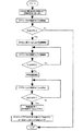
図1は、本発明の実施例1に係るカラー画像形成装置を示す概略構成図である。本例の画像形成装置は電子写真方式のタンデム型のフルカラープリンタである。
(1) Example of Image Forming Apparatus FIG. 1 is a schematic configuration diagram showing a color image forming apparatus according to Embodiment 1 of the present invention. The image forming apparatus of the present embodiment is a tandem type full color printer of an electrophotographic system.
この画像形成装置は、イエロー色の画像を形成する画像形成部1Yと、マゼンタ色の画像を形成する画像形成部1Mと、シアン色の画像を形成する画像形成部1Cと、ブラック色の画像を形成する画像形成部1Bkの4つの画像形成部(画像形成ユニット)を備えており、これらの4つの画像形成部は一定の間隔をおいて一列に配置されている。
The image forming apparatus includes an
各画像形成部1Y、1M、1C、1Bkには、それぞれ感光ドラム2a、2b、2c、2dが設置されている。各感光ドラム2a、2b、2c、2dの周囲には、帯電ローラ3a、3b、3c、3d、現像装置4a、4b、4c、4d、転写ローラ5a、5b、5c、5d、ドラムクリーニング装置6a、6b、6c、6dがそれぞれ設置されており、帯電ローラ3a、3b、3c、3dと現像装置4a、4b、4c、4d間の上方には露光装置7a、7b、7c、7dがそれぞれ設置されている。各現像装置4a、4b、4c、4dには、それぞれイエロートナー、マゼンタトナー、シアントナー、ブラックトナーが収納されている。
画像形成部1Y、1M、1C、1Bkの各感光ドラム2a、2b、2c、2dの各1次転写部Nに、転写媒体としての無端ベルト状の中間転写体40が当接している。中間転写ベルト40は、駆動ローラ41、支持ローラ42、2次転写対向ローラ43間に張架されており、駆動ローラ41の駆動によって矢印方向(時計方向)に回転(移動)される。
An endless belt-shaped
1次転写用の各転写ローラ5a、5b、5c、5dは、各1次転写ニップ部Nにて中間転写ベルト40を介して各感光ドラム2a、2b、2c、2dに当接している。
The
2次転写対向ローラ43は、中間転写ベルト40を介して2次転写ローラ44と当接して、2次転写部Mを形成している。2次転写ローラ44は、中間転写ベルト40に接離自在に設置されている。
The secondary
中間転写ベルト40の外側の駆動ローラ41近傍には、中間転写ベルト40の表面に残った転写残トナーを除去して回収するベルトクリーニング装置45が設置されている。
A
また、2次転写部Mの記録材Pの搬送方向下流側には定着装置12が設置されている。
Further, a fixing
また、この画像形成装置内には環境センサ50とメディアセンサ51が設置されている。
Further, an
画像形成動作開始信号(プリント開始信号)が発せられると、所定のプロセススピードで回転駆動される画像形成部1Y、1M、1C、1Bkの各感光ドラム2a、2b、2c、2dは、それぞれ帯電ローラ3a、3b、3c、3dによって一様に本実施例では負極性に帯電される。
When an image forming operation start signal (print start signal) is issued, each of the
そして、露光装置7a、7b、7c、7dは、入力されるカラー色分解された画像信号をレーザ出力部(不図示)にて光信号にそれぞれ変換し、変換された光信号であるレーザ光を帯電された各感光ドラム2a、2b、2c、2d上にそれぞれ走査露光して静電潜像を形成する。
The
そして、まず静電潜像が形成された感光ドラム2a上に、感光ドラム2aの帯電極性(負極性)と同極性の現像バイアスが印加された現像装置4aによりイエローのトナーを感光体表面の帯電電位に応じて静電吸着させることで静電潜像を顕像化し、現像像とする。このイエローのトナー像は、1次転写部Nにて1次転写バイアス(トナーと逆極性(正極性))が印加された転写ローラ5aにより、回転している中間転写ベルト40上に1次転写される。イエローのトナー像が転写された中間転写ベルト40は画像形成部1M側に回転される。
First, the yellow toner is charged on the surface of the photosensitive member by the developing
そして、画像形成部1Mにおいても、前記同様にして感光ドラム2bに形成されたマゼンタのトナー像が、中間転写ベルト40上のイエローのトナー像上に重ね合わせて、1次転写部Nにて転写される。
In the image forming section 1M, the magenta toner image formed on the
以下、同様にして中間転写ベルト40上に重畳転写されたイエロー、マゼンタのトナー像上に、画像形成部1C、1Bkの感光ドラム2c、2dで形成されたシアン、ブラックのトナー像を各1次転写部Nにて順次重ね合わせて、フルカラーのトナー像を中間転写ベルト40上に形成する。
Thereafter, the cyan and black toner images formed by the
そして、中間転写ベルト40上のフルカラーのトナー像先端が2次転写部Mに移動されるタイミングに合わせて、レジストローラ46により記録材(転写材)Pを2次転写部Mに搬送して、この記録材Pに、2次転写バイアス(トナーと逆極性(正極性))が印加された2次転写ローラ44によりフルカラーのトナー像が一括して2次転写される。フルカラーのトナー像が形成された記録材Pは定着装置12に搬送されて、定着ベルト20と加圧ローラ22間の定着ニップ部でフルカラーのトナー像を加熱、加圧して記録材P表面に溶融定着した後に外部に排出され、画像形成装置の出力画像となる。そして、一連の画像形成動作を終了する。
Then, the recording material (transfer material) P is conveyed to the secondary transfer unit M by the
尚、画像形成装置内には環境センサ50を有しており、帯電、現像、1次転写、2次転写のバイアスや定着条件は画像形成装置内の雰囲気環境(温度、湿度)に応じて変更可能な構成となっており、記録材Pに形成されるトナー像濃度の調整のためや、最適な転写、定着条件を達成するために用いられる。また、画像形成装置内にはメディアセンサ51を有しており、記録材Pの判別を行うことによって、転写バイアスや定着条件は記録材に応じて変更可能な構成となっており、記録材Pに対する最適な転写、定着条件を達成するため用いられる。
Note that the image forming apparatus has an
上記した1次転写時において、感光ドラム2a、2b、2c、2d上に残留している1次転写残トナーは、ドラムクリーニング装置6a、6b、6c、6dによって除去されて回収される。また、2次転写後に中間転写ベルト40上に残った2次転写残トナーは、ベルトクリーニング装置45によって除去されて回収される。
At the time of the primary transfer, the primary transfer residual toner remaining on the
(2)定着装置12
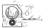
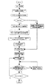
図2は本実施例における定着装置12の概略構成模型図である。本例の定着装置12は、定着ベルト加熱方式、加圧用回転体駆動方式(テンションレスタイプ)の加熱装置である。
(2) Fixing
FIG. 2 is a schematic model diagram of the fixing
1)装置12の全体的構成
20は第一の回転体(第一の定着部材)としての定着ベルトであり、ベルト状部材に弾性層を設けてなる円筒状(エンドレスベルト状、スリーブ状)の部材である。この定着ベルト20は後記6)項で詳述する。
1) Overall Configuration of Apparatus 12 A fixing
22は第二の回転体(第二の定着部材)としての加圧ローラである。17は加熱体保持部材としての、横断面略半円弧状樋型の耐熱性・剛性を有するヒータホルダ、16は加熱体(熱源)としての定着ヒータであり、ヒータホルダ17の下面に該ホルダの長手に沿って配設してある。定着ベルト20はこのヒータホルダ17にルーズに外嵌させてある。定着ヒータ16は本実施例では後記2)項で詳述するようなセラミックヒータである。
ヒータホルダ17は、耐熱性の高い液晶ポリマー樹脂で形成し、定着ヒータ16を保持し、定着ベルト20をガイドする役割を果たす。本実施例においては、液晶ポリマーとして、デュポン社のゼナイト7755(商品名)を使用した。ゼナイト7755の最大使用可能温度は、約270℃である。
The
加圧ローラ22は、ステンレス製の芯金に、射出成形により、厚み約3mmのシリコーンゴム層を形成し、その上に厚み約40μmのPFA樹脂チューブを被覆してなる。この加圧ローラ22は芯金の両端部を装置フレーム24の不図示の奥側と手前側の側板間に回転自由に軸受保持させて配設してある。この加圧ローラ22の上側に、前記の定着ヒータ16・ヒータホルダ17・定着ベルト20等から成る定着ベルトユニットをヒータ16側を下向きにして加圧ローラ22に並行に配置し、ヒータホルダ17の両端部を不図示の加圧機構により片側98N(10kgf)、総圧196N(20kgf)の力で加圧ローラ22の軸線方向に附勢することで、定着ヒータ16の下向き面を定着ベルト20を介して加圧ローラ22の弾性層に該弾性層の弾性に抗して所定の押圧力をもって圧接させ、加熱定着に必要な所定幅の定着ニップ部27を形成させてある。加圧機構は、圧解除機構を有し、ジャム処理時等に、加圧を解除し、記録材Pの除去が容易な構成となっている。
The
18と19は第一と第二の温度検知手段としてのメインとサブの2つのサーミスタである。第一の温度検知手段としてのメインサーミスタ18は加熱体である定着ヒータ16に非接触に配置され、本実施例ではヒータホルダ17の上方において定着ベルト20の内面に弾性的に接触させてあり、定着ベルト20の内面の温度を検知する。第二の温度検知手段としてのサブサーミスタ19はメインサーミスタ18よりも熱源である定着ヒータ16に近い場所に配置され、本実施例では定着ヒータ16の裏面に接触させてあり、定着ヒータ16裏面の温度を検知する。
メインサーミスタ18は、ヒータホルダ17に固定支持させたステンレス製のアーム25の先端にサーミスタ素子が取り付けられ、アーム25が弾性揺動することにより、定着ベルト20の内面の動きが不安定になった状態においても、サーミスタ素子が定着ベルト20の内面に常に接する状態に保たれる。
The
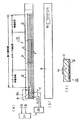
図3に、本実施例の定着装置における、定着ヒータ16、メインサーミスタ18、サブサーミスタ19の位置関係をあらわす斜視模型図を示す。メインサーミスタ18は定着ベルト20の長手中央付近に、サブサーミスタ19は定着ヒータ16の端部付近に配設され、それぞれ定着ベルト20の内面、定着ヒータ16の裏面に接触するよう配置されている。
FIG. 3 is a perspective model diagram showing a positional relationship between the fixing
メインサーミスタ18、及びサブサーミスタ19は、その出力がそれぞれA/Dコンバータ64・65を介して制御回路部(CPU)21に接続され、制御回路部21は、メインサーミスタ18、サブサーミスタ19の出力をもとに、定着ヒータ16の温調制御内容を決定し、電力供給部(加熱手段)としてのヒータ駆動回路部28(図2・図4)によって定着ヒータ16への通電を制御する。
The outputs of the
23と26は装置フレーム24に組付けた入り口ガイドと定着排紙ローラである。入り口ガイド23は、二次転写ニップを抜けた記録材Pが、定着ヒータ16部分における定着ベルト20と加圧ローラ22との圧接部である定着ニップ部27に正確にガイドされるよう、転写材を導く役割を果たす。本実施例の入り口ガイド23は、ポリフェニレンサルファイド(PPS)樹脂により形成されている。
加圧ローラ22は駆動手段(図不示)により矢印の方向に所定の周速度で回転駆動される。この加圧ローラ22の回転駆動による該加圧ローラ22の外面と定着ベルト20との、定着ニップ部27における圧接摩擦力により円筒状の定着ベルト20に回転力が作用して該定着ベルト20がその内面側が定着ヒータ16の下向き面に密着して摺動しながらヒータホルダ17の外回りを矢印の方向に従動回転状態になる。定着ベルト20内面にはグリスが塗布され、ヒータホルダ17と定着ベルト20内面との摺動性を確保している。
The
加圧ローラ22が回転駆動され、それに伴って円筒状の定着ベルト20が従動回転状態になり、また定着ヒータ16に通電がなされ、該定着ヒータ16が昇温して所定の温度に立ち上げ温調された状態において、定着ニップ部27の定着ベルト20と加圧ローラ22との間に未定着トナー像を担持した記録材Pが入り口ガイド23に沿って案内されて導入され、定着ニップ部27において記録材Pのトナー像担持面側が定着ベルト20の外面に密着して定着ベルト20と一緒に定着ニップ部27を挟持搬送されていく。この挟持搬送過程において、定着ヒータ16の熱が定着ベルト20を介して記録材Pに付与され、記録材P上の未定着トナー像tが記録材P上に加熱・加圧されて溶融定着される。定着ニップ部27を通過した記録材Pは定着ベルト20から曲率分離され、定着排紙ローラ26で排出される。
The
2)メインサーミスタ18
メインサーミスタ18は図2,3に示すように、定着ベルト20の長手中央付近に配置され、定着ベルト20の内面に接触するよう配置されている。このメインサーミスタ18は、定着ニップ部の温度により近い温度である定着ベルト20の温度を検出する手段として用いている。よって、通常の動作においては、メインサーミスタ18の検知温度が目標温度になるよう、温調制御される。
2)
As shown in FIGS. 2 and 3, the
3)サブサーミスタ19
サブサーミスタ19は図3に示すように、定着ヒータ16の端部付近に配設され、定着ヒータ16の裏面に接触するよう配置されている。このサブサーミスタ19は、加熱体である定着ヒータ16の温度を検出し、定着ヒータの温度が所定温度以上にならないようにモニターする、安全装置としての役割を果たしている。
また、サブサーミスタ19により、立ち上げ時の定着ヒータ16の温度のオーバーシュートや、端部の昇温をモニターし、例えば端部の昇温により定着ヒータ20の端部の温度が所定の温度を超えた場合には、それ以上に端部昇温が悪化しないようにスループットを落とす等の制御を行う為の判断に用いられる。
3)
As shown in FIG. 3, the
Further, the sub-thermistor 19 monitors the overshoot of the temperature of the fixing
4)定着ヒータ16
熱源としての定着ヒータ16は、本実施例では、窒化アルミの基板上に、銀・パラジウム合金を含んだ導電ペーストをスクリーン印刷法によって均一な厚さの膜状に塗布することで抵抗発熱体を形成した上に耐圧ガラスによるガラスコートを施した、セラミックヒータを使用している。
4) Fixing
In the present embodiment, the fixing
図4はそのようなセラミックヒータの一例の構造模型図であり、(a)は一部切欠き表面模型図、(b)は裏面模型図、(c)は拡大横断面模型図である。 FIGS. 4A and 4B are structural model diagrams of an example of such a ceramic heater. FIG. 4A is a partially cutaway surface model diagram, FIG. 4B is a rear model diagram, and FIG. 4C is an enlarged cross-sectional model diagram.
この定着ヒータ16は、
a.通紙方向と直交する方向を長手とする横長の窒化アルミ基板a、
b.上記の窒化アルミ基板aの表面側に長手に沿ってスクリーン印刷により線状あるいは帯状に塗工した、電流が流れることにより発熱する銀パラジウム(Ag/Pd)合金を含んだ導電ペーストの、厚み10μm程度、幅1〜5mm程度の抵抗発熱体層b、
c.上記の抵抗発熱体層bに対する給電パターンとして、同じく窒化アルミ基板aの表面側に銀ペーストのスクリーン印刷等によりパターン形成した、第1と第2の電極部c・d及び延長電路部e・f、
d.抵抗発熱体層bと延長電路部e・fの保護と絶縁性を確保するためにそれ等の上に形成した、定着ベルト20との摺擦に耐えることが可能な、厚み10μm程度の薄肉のガラスコートg、
e.窒化アルミ基板aの裏面側に設けたサブサーミスタ19
等からなる。
The fixing
a. A horizontally long aluminum nitride substrate a whose longitudinal direction is the direction perpendicular to the paper passing direction,
b. A 10 μm thick conductive paste containing a silver-palladium (Ag / Pd) alloy, which is applied in a linear or band shape by screen printing on the surface side of the aluminum nitride substrate a along its length and generates heat when a current flows. Resistance heating element layer b having a width of about 1 to 5 mm,
c. As a power supply pattern for the resistance heating element layer b, first and second electrode portions c and d and extended electric circuit portions e and f are also formed on the surface side of the aluminum nitride substrate a by screen printing of silver paste or the like. ,
d. In order to protect the resistance heating element layer b and the extended electric circuit portions e and f and to secure insulation, the thin film having a thickness of about 10 μm, which can withstand rubbing with the fixing
e.
Etc.
上記の定着ヒータ16は表面側を下向きに露呈させてヒータホルダ17に固定して支持させてある。
The fixing
上記定着ヒータ16の第1と第2の電極部c・d側には給電用コネクタ30が装着される。ヒータ駆動回路部28から上記の給電用コネクタ30を介して第1と第2の電極部c・dに給電されることで抵抗発熱体層bが発熱して定着ヒータ16が迅速に昇温する。ヒータ駆動回路部28は制御回路部(CPU)21により制御される。
A
通常使用においては、加圧ローラ22の回転開始とともに、定着ベルト20の従動回転が開始し、定着ヒータ16の温度の上昇とともに、定着ベルト20の内面温度も上昇していく。定着ヒータ16への通電は、PID制御によりコントロールされ、定着ベルト20の内面温度、すなわち、メインサーミスタ18の検知温度が190℃になるように、入力電力が制御される。
In normal use, the driven rotation of the fixing
5)定着ヒータ駆動回路部28
図5は定着手段の温度制御手段としての制御回路部(CPU)21と定着ヒータ駆動回路部28のブロック図である。上記定着ヒータ16の給電用電極部c・dは給電コネクタ(不図示)を介してこの定着ヒータ駆動回路部28に接続されている。
5) Fixing heater
FIG. 5 is a block diagram of a control circuit unit (CPU) 21 as a temperature control unit of the fixing unit and a fixing heater
定着ヒータ駆動回路部28において、60は交流電源、61はトライアック、62はゼロクロス発生回路、21は制御回路部(CPU)である。トライアック61は制御回路部21により制御される。トライアック61は定着ヒータ16の発熱抵抗体層bに対する通電・遮断を行う。
In the fixing heater
交流電源60はゼロクロス検知回路62を介して制御回路部21にゼロクロス信号を送出する。制御回路部21はこのゼロクロス信号を基にトライアック61を制御する。このようにして定着ヒータ駆動回路部28から定着ヒータ16の発熱抵抗体層bに通電されることで、定着ヒータ16の全体が急速昇温する。
The
定着ベルト20の温度を検知するメインサーミスタ18と定着ヒータ16の温度を検知するサブサーミスタ19の出力はそれぞれA/Dコンバータ64・65を介して制御回路部(CPU)21に取り込まれる。
The outputs of the
制御回路部21はメインサーミスタ18からの定着ヒータ16の温度情報をもとにトライアック61により定着ヒータ16に通電するAC電圧を位相、波数制御等により、ヒータ通電電力を制御して定着ヒータ16の温度が所定の制御目標温度(設定温度)に維持されるように制御する。
The
すなわち、メインサーミスタ18、サブサーミスタ19の温度は電圧値として制御回路部21でモニターされ、これにより定着ベルト20の温度が所定の設定温度に温調維持されるように、また定着ヒータの16が所定温度内で駆動されるように定着ヒータ16への通電電力の制御が行われる。
That is, the temperatures of the
代表的な温度制御方式としてはPID制御が用いられる。また電力の制御法としては、波数制御や位相制御などがあるが、ここでは位相制御を用いて説明する。 PID control is used as a typical temperature control method. As a power control method, there are a wave number control, a phase control, and the like. Here, the phase control will be described.
すなわちメインサーミスタ18の温度を制御回路部21が2μsecごとに検知し、制御回路部21内で所望の温調温度に制御するようにPID制御にて定着ヒータ16への電力供給量を決定する。たとえば電力の指定を5%刻みで行うには、一般に電源から供給される交流波形の1半波にたいして5%刻みの通電角を用いて行われる。通電角はゼロクロス発生回路62にてゼロクロス信号を検知したときを起点にトライアック61をONするタイミングとして求められる。
That is, the
6)定着ベルト20
本実施例において、定着ベルト20はベルト状部材に弾性層を設けてなる円筒状(エンドレスベルト状)の部材である。
具体的には、SUSにより、厚み30μmの円筒状に形成したエンドレスベルト(ベルト基材)上に、厚み約300μmのシリコーンゴム層(弾性層)を、リングコート法により形成した上に、厚み30μmのPFA樹脂チューブ(最表面層)を被覆してなる。このような構成で作成した定着ベルト20の熱容量を測定したところ、12.2×10⁻²J/cm2・℃(定着ベルト1cm2あたりの熱容量)であった。
6) Fixing
In this embodiment, the fixing
Specifically, a silicone rubber layer (elastic layer) having a thickness of about 300 μm is formed on a cylindrical endless belt (belt base material) having a thickness of 30 μm by SUS by a ring coating method, and then a thickness of 30 μm is formed. Of the PFA resin tube (outermost surface layer). When the heat capacity of the fixing
a.定着ベルトの基層
定着ベルト20の基層にはポリイミドなどの樹脂を用いることも出来るが、ポリイミドよりもSUSやニッケルといった、金属のほうが、熱伝導率がおよそ10倍と大きく、より高いオンデマンド性を得られることから、本実施例においては、定着ベルト20の基層には、金属であるSUSを用いた。
a. Resin such as polyimide can be used for the base layer of the fixing
b.定着ベルトの弾性層
定着ベルト20の弾性層には、比較的熱伝導率の高いゴム層を用いている。これはより高いオンデマンド性を得る為である。本実施例で用いた材質は比熱が約12.2×10⁻¹J/g・℃である。
b. Elastic Layer of Fixing Belt As the elastic layer of the fixing
c.定着ベルトの離形層
定着ベルト20の表面には、フッ素樹脂層を設けることで、表面の離型性を向上し、定着ベルト20表面にトナーが一旦付着し、再度記録材Pに移動することで発生するオフセット現象を防止することができる。また、定着ベルト20の表面のフッ素樹脂層を、PFAチューブとすることで、より簡便に、均一なフッ素樹脂層を形成することが可能となる。
c. Release Layer of Fixing Belt By providing a fluororesin layer on the surface of the fixing
d.定着ベルトの熱容量
一般に、定着ベルト20の熱容量が大きくなると、温度立ち上がりが鈍くなり、オンデマンド性が損なわれる。たとえば、定着装置の構成にも拠るが、スタンバイ温調無しで、1分以内での立ち上がりを想定した場合、定着ベルト20の熱容量は約4.2J/cm2・℃以下である必要があることが分かっている。
d. Heat Capacity of Fixing Belt Generally, when the heat capacity of the fixing
本実施例においては、室温状態からの立ち上げの際に、定着ヒータ16に約1000Wの電力を投入して、定着ベルト20が190℃に20秒以内に立ち上がる様に設計してある。シリコーンゴム層には、比熱が約12.2×10⁻¹J/g・℃の材質を用いており、このとき、シリコーンゴムの厚みは500μm以下でなければならなく、定着ベルト20の熱容量は約18.9×10−2J/cm2・℃以下である必要がある。また、逆に、4.2×10−2J/cm2・℃以下にしようとすると、定着ベルト20のゴム層が極端に薄くなり、OHT透過性やグロスムラなどの画質の点において、弾性層を持たないオンデマンド定着装置と同等になってしまう。
In the present embodiment, at the time of startup from a room temperature state, an electric power of about 1000 W is applied to the fixing
本実施例においては、OHT透過性やグロスの設定など高画質な画像を得るために必要なシリコーンゴムの厚みは200μm以上であった。この際の熱容量は8.8×10⁻²J/cm2・℃であった。 In this embodiment, the thickness of the silicone rubber necessary for obtaining a high-quality image such as OHT transparency and gloss setting was 200 μm or more. The heat capacity at this time was 8.8 × 10 −2 J / cm 2 · ° C.
つまり、本実施例と同様の定着装置の構成における、定着ベルト20の熱容量は4.2×10⁻²J/cm2・℃以上4.2J/cm2・℃以下が一般的に対象となる。この中で、よりオンデマンド性と高画質の両立を図ることができる、熱容量8.8×10−2J/cm2・℃以上18.9×10−2J/cm2・℃以下の定着ベルトを用いることとした。
In other words, the heat capacity of the fixing
(3)定着装置への入力される最大供給電力の予測方法
本実施例では、定着ヒータ16に通電開始してからメインサーミスタ18の検知温度の上昇時間に従い、定着ヒータ16への最大供給電力値を予測し、定着装置の安定動作に必要な電力値の出力時に、出力電力を最大供給電力値に従い補正することによって、入力電圧のばらつきや定着ヒータ16の抵抗値のばらつきによらず、オーバーシュート/アンダーシュートを防止し、立ち上げ時や通紙開始時においても安定した温度制御を行う。上記の制御は制御回路部(CPU)21でなされる。
(3) Method of Predicting Maximum Supply Power Input to Fixing Device In the present embodiment, the maximum supply power value to fixing
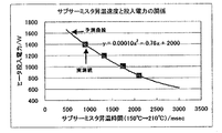
本実施例においては、定着装置に入力される最大供給電力の予測方法として、立ち上がり温調中にフル電力(100%)を供給し、加熱体である定着ヒータ16の昇温時間を、サブサーミスタ19の検知温度から測定することにより、最大供給電力の予測をおこなう。具体的には、立ち上がり温調中にサブサーミスタ19の検知温度が150℃から210℃まで昇温するのにかかる時間T(msec)を測定し、予想される最大供給電力E(W)を以下の(1)式にて算出する。
In the present embodiment, as a method of estimating the maximum supply power input to the fixing device, full power (100%) is supplied during startup temperature control, and the temperature rise time of the fixing
E=2000−0.76×T+0.00010×T2・・・(1)
ここで用いた予想式は、本実施例で説明した構成をとった定着装置において、最適化されたものであり、発明が適用される装置の構成や各種条件により適宜変更されるべきものである。もちろん、立ち上がり上昇カーブの時間を測定する温度範囲によって変化することは言うまでもない。
E = 2000−0.76 × T + 0.00010 × T2 (1)
The prediction formula used here is optimized in the fixing device having the configuration described in this embodiment, and should be appropriately changed according to the configuration of the device to which the invention is applied and various conditions. . It goes without saying that the temperature varies depending on the temperature range in which the time of the rising rise curve is measured.
つまりは、立ち上がり上昇カーブの時間と投入電力の関係として、
E=α+β×T+λ×T2・・・(2)
を用いることとし、本実施例で説明した構成をとった定着装置において、サブサーミスタ19の検知温度が150℃から210℃まで昇温するのにかかる昇温時間と投入電力の関係を示すときには、(1)式のように係数を採った場合がよく一致することからこのような予想式を用いることとした。また、制御回路部(CPU)21への負担を低減する為に簡単な係数を用いた。予想式には必ずしも2次の多項式を用いなければいけないわけではなく、定着装置の構成によっては、2次の項を省略することや、更に高次の項を用いる、もしくは他の形の式を用いてもかまわない。
In other words, as the relationship between the time of the rise curve and the input power,
E = α + β × T + λ × T2 (2)
In the fixing device having the configuration described in the present embodiment, when the relationship between the heating time required for the detection temperature of the
図5に上記の予想式と実測値を比較した結果を示す。サブサーミスタ19の検知温度が150℃から210℃まで昇温するのにかかる時間は、試験に用いたインライン型の電子写真方式カラー画像形成装置内において、サーミスタの出力をA/D変換して、測定される。一方、実際に供給される電力についてはYOKOGAWA製WT200 DIGITAL POWER METERを介して電力値の出力を同じくキーエンス製PC用温度レコーダーNR250にてA/D変換しPCに取り込むことにより測定した。
FIG. 5 shows the result of comparison between the above-mentioned prediction formula and actual measurement values. The time required for the detection temperature of the
図5に示すように、実測値と予想式は良く一致し、本実施例を用いることで、最大供給電力が精度良く求まる事が分かる。 As shown in FIG. 5, the measured value and the prediction formula agree well, and it is understood that the maximum supply power can be accurately obtained by using this embodiment.
本実施例においては、立ち上がり温調を利用した最大供給電力の予測は、立ち上げ温調前に、サブサーミスタ19の検知温度が測定範囲を超えている場合は、予測値を算出できない為、立ち上げ温調前に、サブサーミスタ19の検知温度が140℃以上の時には予測値の更新を行わないこととしてある。
In the present embodiment, the prediction of the maximum supply power using the rising temperature control is performed when the detected temperature of the
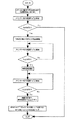
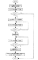
図16に本実施例における定着装置へ入力される最大供給電力の予測方法についてのフローチャートを示す。このようにしてサブサーミスタの検知温度を用いることによって、最大供給電力を精度良く求める事ができる。
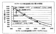
本実施例においては、立ち上がり上昇カーブの時間を測定する温度範囲として、サブサーミスタ19の検知温度が150℃から210℃までとして説明した。この範囲は、以下のような条件から決定される。
FIG. 16 is a flowchart illustrating a method of estimating the maximum supply power input to the fixing device according to the present exemplary embodiment. By using the detected temperature of the sub thermistor in this way, the maximum supply power can be accurately obtained.
In the present embodiment, the temperature range for measuring the time of the rising rise curve has been described assuming that the detected temperature of the
1)温度範囲の低温下限について
・下限はサブサーミスタの初期温度であり、少なくとも使用温度環境以上となる
・低温側を用いた場合、上昇カーブが急峻すぎて電力予想の誤差が大きくなる
・使用温度環境や、定着装置の蓄熱状態に影響を受ける(場合によっては補正
を必要とする)
2)温度範囲の高温上限について
・上限は立ち上げ時の最大駆動温度となる
・上限が高いほど上昇カーブの測定時間が長くなる為、電力予想の反映が遅く
なる
このような観点から、立ち上がり上昇カーブの時間を測定する温度範囲として、サブサーミスタ19の検知温度が150℃から210℃までを最も好ましい条件として使用した。上昇カーブの温度範囲は、上記条件から70℃以上230℃以下の何れかの範囲を用いることが好適であったが、その範囲以内で使用する必要は必ずしもない。
1) Low temperature lower limit of temperature range-The lower limit is the initial temperature of the sub thermistor, which is at least higher than the operating temperature environment.-When the low temperature side is used, the rising curve is too steep to increase the error in power estimation.-Operating temperature Affected by the environment and the heat storage state of the fixing device (correction may be required in some cases)
2) Regarding the high temperature upper limit of the temperature range-The upper limit is the maximum drive temperature at startup.-The higher the upper limit, the longer the measurement time of the rise curve, and the slower the reflection of the power forecast. As the temperature range for measuring the time of the curve, the detection temperature of the
(4)定着装置の温度制御
本実施例では、定着ベルト20の内面にメインサーミスタ18を当接させることにより、定着ベルトの温度を検出し、PID制御などのフィードバック制御により定着ヒータ16の投入電力を制御する方法を基本として温調制御を行っている。
(4) Temperature Control of the Fixing Device In this embodiment, the temperature of the fixing belt is detected by bringing the
一方、定着装置の立ち上げ時と通紙開始時においては、更なる温調精度の向上とオーバーシュート/アンダーシュートの防止のために、次のような制御を行っている。以下に詳細を述べる。 On the other hand, at the time of starting the fixing device and at the time of starting the sheet feeding, the following control is performed in order to further improve the temperature control accuracy and prevent overshoot / undershoot. The details are described below.
1)立ち上げ時の温度制御
本実施例においては、速やかに、且つ、過度のオーバーシュートを発生させること無く立ち上げる為に、立ち上げ温調中にフィードバック制御を禁止する領域を設け、複数電力レベルを用いて電力制御を行うことによって、オーバーシュートを生じることなく、安定した温度制御を行っている。
1) Temperature Control at Startup In this embodiment, in order to start up quickly and without excessive overshoot, an area where feedback control is prohibited during start-up temperature control is provided. By performing power control using the level, stable temperature control is performed without causing overshoot.
本実施例においては、複数の電力レベルとして、定着ヒータ16に投入される電力に、定着装置温度をすみやかに立ち上げるための第一電力レベルと、オーバーシュートを防止し、定着装置温度を安定させるための第二電力レベルとを用い、立ち上げ温調中に所定タイミングで切り替えている。
In the present embodiment, as the plurality of power levels, the power supplied to the fixing
また、第二電力レベルは、定着装置の蓄熱具合を考慮した必要電力値に適宜補正している。 The second power level is appropriately corrected to a required power value in consideration of the heat storage condition of the fixing device.
具体的には以下に述べるような制御を行っている。 Specifically, the following control is performed.
本実施例においては、「立ち上げ第一電力出力(100%フル出力)」→「昇温時間検知(最大供給電力予測)」→「補正した立ち上げ第一電力投入」→「所定温度検知」→「補正した立ち上げ第二電力投入」→「補正したPID制御」、と立ち上げ制御を行う。 In the present embodiment, “first startup power output (100% full output)” → “heat-up time detection (predicted maximum supply power)” → “corrected first startup power input” → “predetermined temperature detection” Start-up control is performed in the order of “corrected start-up second power input” → “corrected PID control”.
まず、電力の補正方法について述べる。 First, a power correction method will be described.
電力の補正には以下のような補正式を用いることとした。
ここで、基準とする最大供給電力として、1050Wを用いたのは、使用条件での典型的な最大供給電力である為である。この基準は適宜変更しても良い。 Here, 1050 W is used as the reference maximum supply power because it is a typical maximum supply power under use conditions. This criterion may be changed as appropriate.
前述した補正を行った場合の結果を表3に示す。例えば、最大供給電力が1050Wのときに、出力電力が50%の出力を行うべきところで、最大供給電力がそれぞれ750W、1500Wの時には、それぞれ、フル電力の67.8%、38.5%を出力することにより、結果として同じ電力を出力する。このような補正を行わないと、最大供給電力が750W、1500Wの時にそれぞれ325W、750Wの電力が出力されてしまう。ただし、最大供給電力であるフル電力(100%)以上は出力できないので、その場合は100%の出力とする。 Table 3 shows the results of the above-described correction. For example, when the maximum supply power is 1050 W, the output power should be 50%, and when the maximum supply power is 750 W and 1500 W, respectively, 67.8% and 38.5% of the full power are output, respectively. By doing so, the same power is output as a result. Unless such correction is performed, 325 W and 750 W of power are output when the maximum supply power is 750 W and 1500 W, respectively. However, the output cannot be more than the full power (100%) which is the maximum supply power. In this case, the output is set to 100%.
ここで示すのは、普通紙モードとOHTモードの温調温度である。このように、カウント数が進むにつれ、つまりは加圧ローラ22の予想温度が上がるにつれて、温調温度を下げるようにした。
Shown here are the temperature control temperatures in the plain paper mode and the OHT mode. As described above, as the count number advances, that is, as the expected temperature of the
以上説明したように、定着装置の立ち上げ回数に従ったカウント値を用いることで、定着装置の使用状態によらず、加圧ローラ温度を精度良く予想し、その加圧ローラの温度に従った温調温度を選択することによって、定着温調温度が不適切な場合に発生する画像不良を発生させることや記録材の巻きつきを発生させることが無く、良好な定着性を示し、グロス値などの印字品質ムラがない高画質な画像を得ることができる。 As described above, by using the count value in accordance with the number of startups of the fixing device, the temperature of the pressure roller is accurately predicted regardless of the use state of the fixing device, and the temperature of the pressure roller is predicted. By selecting the temperature control temperature, it does not cause image defects that occur when the fixing temperature control temperature is inappropriate and does not cause wrapping of the recording material. And a high quality image without uneven printing quality can be obtained.
このように、予想される最大供給電力に従い、出力電力率を補正することにより、最大供給電力のばらつきによらず、安定した温度制御を行うことができる。従って、電力制御を最大供給電力が1050Wのときに最適になるように、制御パラメータを最適化すれば、その他の電力の場合においても、前述した補正を行うことにより最適な制御が行われることとなる。 As described above, by correcting the output power rate according to the expected maximum supply power, stable temperature control can be performed regardless of the variation in the maximum supply power. Therefore, by optimizing the control parameters such that the power control is optimized when the maximum supply power is 1050 W, the optimum control is performed by performing the above-described correction even in the case of other powers. Become.
次に、立ち上げ第一電力や第二電力の出力タイミングについて述べる。 Next, the output timing of the first power up and the second power up will be described.
立ち上げ第一電力(100%)出力後、立ち上げ第一電力の補正のタイミングは、サブサーミスタ19の検知温度が150℃から210℃まで昇温するのにかかる時間を測定して、前述した方法により、最大供給電力の予測値が決定した時点で行われることとした。補正した立ち上げ第一電力出力後、第二電力に切り替えるタイミングと、第二電力の投入時間は、表4に示すようにすることとした。表に示した以外の電力においてはこの表にある電力から線形補間したものを用いる。
After the output of the first power (100%), the correction of the first power is performed by measuring the time required for the detected temperature of the
このように、最大供給電力によって切り替えタイミングを変える理由は次のとおりである。 The reason why the switching timing is changed according to the maximum supply power is as follows.
・最大供給電力が大きい場合には、フル電力を投入し、サブサーミスタ19により最大供給電力の予想を終えるまでの間の定着ヒータ16の昇温の大きさが大きいことを考慮して、早めに第二電力に切り替える。その分、第二電力の投入時間は長く取る。
When the maximum supply power is large, full power is supplied, and the temperature rise of the fixing
・最大供給電力が小さい場合には、最大供給電力の予想が終わった後、補正される出力電力率は100%以上を出力できないため、立ち上げ時間を早めるために、第一電力の投入時間を出来るだけ長くする。その分、第二電力の投入時間は短くする。
-When the maximum supply power is small, after the prediction of the maximum supply power is over, the output power ratio to be corrected cannot
このようにすることにより、最大供給電力のばらつきによらずオーバーシュートの小さい温度制御を行うことができる。 By doing so, temperature control with a small overshoot can be performed irrespective of variations in the maximum supply power.
2)通紙開始時の温度制御
本実施例においては、通紙開始時の記録材Pの突入タイミングとあわせて、一定時間PID制御を行わず、定着ヒータ16に投入される電力を所定の値に補正して投入する際に、記録材Pの熱的特性や、定着装置の蓄熱具合を考慮した略必要電力値に補正することによって、温度検知のむだ時間(タイムラグ)による通紙開始時の記録材Pの突入に伴う温度変動を生じることなく、安定した温度制御を行っている。
2) Temperature control at the start of sheet feeding In this embodiment, the PID control is not performed for a certain period of time in accordance with the entry timing of the recording material P at the start of sheet feeding, and the power supplied to the fixing
具体的には、通紙前後にPID制御を行い、通紙開始時の記録材突入前の約0.3秒から約0.7秒間はPID制御を行わず通紙時に必要な略必要電力値を投入し、その後PID制御に移行するようにした。例えば、室温状態からの立ち上げ直後の普通紙通紙においては約500Wである。つまりは、基準とする最大供給電力が1050Wの場合においては約47.5%の出力となる。 More specifically, the PID control is performed before and after the paper is fed, and the PID control is not performed for about 0.3 to 0.7 seconds before the recording material enters at the time of the start of the paper feeding, and the substantially required power value required for the paper feeding is not performed. And then shifted to PID control. For example, the power is about 500 W for plain paper passing immediately after startup from a room temperature state. That is, when the reference maximum supply power is 1050 W, the output is about 47.5%.
電力の補正には先述した補正式を同様に用いる。つまり、約500Wを必要とする場面においては、最大供給電力がそれぞれ750W、1500Wの時には、それぞれ、フル電力の約66.5%、33.25%を出力することにより、結果として同じ電力(500W)を出力する。この場合においても、電力制御を最大供給電力が1050Wのときに最適になるように制御パラメータを最適化すれば、その他の電力においても補正することにより最適な制御が行われることとなる。 The correction equation described above is similarly used for power correction. In other words, in a situation where about 500 W is required, when the maximum supply power is 750 W and 1500 W, respectively, about 66.5% and 33.25% of the full power are output, and as a result, the same power (500 W ) Is output. In this case as well, if the control parameters are optimized so that the power control is optimal when the maximum supply power is 1050 W, the optimum control is performed by correcting other power.
尚、本実施例においては、所定電力の投入時間0.7秒は、最大供給電力によって変更できるものとした。これは、最大供給電力が大きい場合には、昇温時間が短いことから比較的予測値の誤差が大きくなり、また、最大供給電力が小さい場合には、昇温時間が長いことから定着装置の蓄熱具合や使用環境等の影響を受け、予測値の誤差が大きくなる為である。つまり、予想式によって求まった予測値の実際の最大供給電力との差分の影響を小さくする為に、最大供給電力が基準とした1050Wから離れている場合には、所定電力の投入時間を若干短くした。具体的には、最大供給電力が1500W以上もしくは700W以下の時には所定電力の投入時間を通紙開始時の記録材突入前の約0.3秒から約0.5秒間とした。
In this embodiment, the predetermined power supply time of 0.7 seconds can be changed by the maximum supply power. This is because when the maximum supply power is large, the error in the predicted value is relatively large because the heating time is short, and when the maximum supply power is small, the heating time is long because the heating time is long. This is because the error in the predicted value increases due to the influence of the heat storage condition and the use environment. That is, in order to reduce the influence of the difference between the predicted value obtained by the prediction formula and the actual maximum supply power, when the maximum supply power is apart from the
3)立ち上げ時の第二電力と、通紙開始時の所定電力投入時間
立ち上げ時の第二電力と、通紙開始時の所定電力投入時間について述べる。
前述したように、定着装置の立ち上げ時と通紙開始時における、サーミスタの検出温度が目標温度に到達するタイミング近傍または記録材の定着ニップ27への突入タイミング近傍に温度変動防止の為の電力の投入を行う必要のあるのは、以下の理由による。
3) Second power at start-up, predetermined power input time at start of sheet passing, second power at start-up, and predetermined power input time at start of sheet feed will be described.
As described above, at the time of starting the fixing device and at the time of starting the sheet feeding, the electric power for preventing the temperature fluctuation near the timing when the detected temperature of the thermistor reaches the target temperature or near the timing when the recording material enters the fixing nip 27. It is necessary to make the input for the following reasons.
a.定着ベルト20の弾性層に用いられるシリコーンゴム層の熱伝導率が小さく、定着ヒータ16から定着ベルト表面までに多くの部材があることにより定着ヒータ16へ通電した後に、定着ベルト温度が上昇するまでの、いわゆる熱応答性が悪いこと。
a. The thermal conductivity of the silicone rubber layer used for the elastic layer of the fixing
b.定着ベルト20の温度を検出する温度検知手段18の位置が定着ニップ27から離れていることによる定着ニップ部の検知タイミングの遅れがあること。
b. The detection timing of the fixing nip portion is delayed due to the position of the temperature detecting means 18 for detecting the temperature of the fixing
aに示すように定着ベルト温度が上昇するまでの、熱応答性が悪いことから、立ち上げ時や、通紙開始時の電力投入時において、定着ベルトは満遍なく暖める為、定着ベルトが略1周分回転する間、必要な電力値を投入していることが望ましい。また、bに示すように、定着ニップ部の温度検知タイミングの遅れがあることから、立ち上げ時や、通紙開始時の電力投入時において、略遅れ時間の分だけ必要な電力値を投入していることが望ましい。 Since the thermal response is poor until the temperature of the fixing belt rises as shown in a, the fixing belt warms up evenly at startup and when power is supplied at the start of paper passing, so that the fixing belt is rotated for approximately one rotation. It is desirable that a necessary electric power value is supplied during the minute rotation. Further, as shown in b, since there is a delay in the temperature detection timing of the fixing nip portion, at the time of startup or at the time of power supply at the time of starting paper feeding, a necessary power value is supplied for substantially the delay time. Is desirable.
よって、定着ベルト20の外周の移動速度として、プロセススピードをV、圧接部から温度検知位置までの長さをa、定着ベルト20外周長をLとしたときに、立ち上げ時の温度を安定させ、通紙開始時に温度挙動を安定させる為に必要な電力の理想的な投入時間は、(a+L)/V近傍である。
Therefore, as the moving speed of the outer periphery of the fixing
一方、実機での使用においては、定着装置の蓄熱具合や使用環境等、そして定着装置の部材・構成のばらつきなどの影響を受け、必要となる電力値と、予測した電力値に誤差が生じる場合がある。誤差を生じている場合、電力を投入している時間が長いほど温調温度は変動してしまう。また、立ち上がりの時間の制約上早期に立ち上げる為に長く電力を投入しつづけられない場合がある。このような理由から、実際の電力の投入時間は、上記の理想的な投入時間よりも短い時間で用いることが望ましい。 On the other hand, when used in an actual machine, an error occurs between the required power value and the predicted power value due to the influence of the heat storage condition of the fixing device, the use environment, etc., and the variation in the members and configuration of the fixing device. There is. When an error occurs, the temperature adjustment temperature fluctuates as the power supply time is longer. In addition, there is a case where it is not possible to keep supplying power for a long time to start up early due to the restriction of the rising time. For this reason, it is desirable to use the actual power supply time shorter than the ideal power supply time.
これらの根拠から、立ち上げ時や、通紙開始時の必要な電力の電力の投入時間として、より好ましい時間tは、以下の式で表すことができる。 From these grounds, a more preferable time t as the required power supply time at the start-up or at the start of paper passing can be expressed by the following equation.
t≦(a+L)/V
本実施例においては、プロセススピード87mm/sec、であり、圧接部から温度検知位置までの長さは20mm、定着ベルト20外周長は77.6mmである為、電力の投入時間は1.12sec以内が好ましい時間である。
t ≦ (a + L) / V
In this embodiment, the process speed is 87 mm / sec, the length from the pressure contact portion to the temperature detection position is 20 mm, and the outer peripheral length of the fixing
もちろん、上記の時間に限定されることなく、本発明を適用することはことはできる。 Of course, the present invention can be applied without being limited to the above time.
4)PID制御
本実施例においては、PID制御によって制御される電力についても、予想される最大供給電力に従い出力電力率を補正することとした。PID制御により決定された出力電力率を先述した補正式を同様に用いて補正する。
4) PID Control In the present embodiment, the output power factor of the power controlled by the PID control is corrected according to the expected maximum supply power. The output power factor determined by the PID control is corrected using the above-described correction formula in the same manner.
従来の定着装置において、PID制御では、例えば目標温度に対して、メインサーミスタの検知温度が2℃足りない場合には、出力電力率を2.5%増加する、というように制御している。本実施例においては、目標温度に対して、メインサーミスタの検知温度が2℃足りない場合には、最大供給電力が750W、1050W、1500Wにおいて、出力電力率をそれぞれ1.79%、2.5%、3.57%増加する。これにより、メインサーミスタの検知温度が2℃足りない場合には、最大供給電力によらず、電力を約26.25W増加させることとなる。 In the conventional fixing device, in the PID control, for example, when the detected temperature of the main thermistor is lower than 2 ° C. with respect to the target temperature, the output power ratio is controlled to increase by 2.5%. In the present embodiment, when the detected temperature of the main thermistor is lower than the target temperature by 2 ° C., the output power rates are 1.79% and 2.5% when the maximum supply power is 750 W, 1050 W and 1500 W, respectively. %, 3.57%. Accordingly, when the detected temperature of the main thermistor is lower than 2 ° C., the power is increased by about 26.25 W regardless of the maximum supplied power.
この場合においても、電力制御を最大供給電力が1050Wのときに最適になるように制御パラメータを最適化すれば、その他の電力においても補正することにより最適な制御が行われることとなる。 In this case as well, if the control parameters are optimized so that the power control is optimal when the maximum supply power is 1050 W, the optimum control is performed by correcting other power.
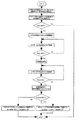
図17に予測される最大投入電力に基づいた定着装置の温度制御のフローチャートを示す。このように、予測される最大投入電力に基づいて電力制御を行うことにより、入力電圧のばらつきや定着ヒータ16の抵抗値のばらつきに伴う最大投入電力の変化によらず、安定した温度制御を行うことができる。
FIG. 17 shows a flowchart of temperature control of the fixing device based on the predicted maximum input power. As described above, by performing power control based on the predicted maximum input power, stable temperature control is performed irrespective of a change in the maximum input power due to a variation in the input voltage or a variation in the resistance value of the fixing
(5)本実施例を用いた場合の実験結果
次に、本実施例を用いた場合の実験結果を示す。
(5) Experimental Results Using This Example Next, experimental results using this example are shown.
1)実験方法
室温状態の定着装置を用いて、立ち上げ後、一枚印字した時のメイン・サブサーミスタ検知温度と定着ヒータ16への投入電力の様子を最大供給電力がそれぞれ800W、880W、1030W、1190W、1440Wの時について、測定した。
1) Experimental method Using the fixing device at room temperature, the state of the main / sub thermistor detection temperature and the power applied to the fixing
各サーミスタの検知温度は、試験に用いたインライン型の電子写真方式カラー画像形成装置内において、サーミスタの出力をA/D変換して、測定される。一方、実際に供給される電力についてはYOKOGAWA製WT200 DIGITAL POWER METERを介して電力値の出力を同じくキーエンス製PC用温度レコーダーNR250にてA/D変換しPCに取り込むことにより測定した。 The detected temperature of each thermistor is measured by A / D converting the output of the thermistor in the in-line type electrophotographic color image forming apparatus used for the test. On the other hand, the actually supplied power was measured by A / D converting the output of the power value via the YOKOGAWA WT200 DIGITAL POWER METER with the Keyence PC temperature recorder NR250 and taking it into the PC.
定着後画像のグロスについては、次の方法を用いて測定を行った。測定器として、日本電色工業株式会社製の光沢計PG―3Dを使用し、JIS Z 8741における75度鏡面光沢測定方法により測定を行った。記録材上のトナー量としては、Y,M,C,BKのいわゆる1次色のべた画像部のトナー量が約0.5〜0.6mg/cm2、R,G,Bのいわゆる2次色のべた部が約1.0〜1.2mg/cm2の状態で定着を行い、定着後画像のグロスを測定した。
The gloss of the image after fixing was measured using the following method. As a measuring device, a gloss meter PG-3D manufactured by Nippon Denshoku Industries Co., Ltd. was used, and the measurement was performed by a 75 ° specular gloss measuring method in JIS Z 8741. As the toner amount on the recording material, the toner amount of the solid image portion of so-called primary colors of Y, M, C, and BK is about 0.5 to 0.6 mg / cm2, and the so-called secondary colors of R, G, and B are used. Fixing was performed with the solid portion being about 1.0 to 1.2 mg /
また、最大供給電力がそれぞれ800W、880W、1030W、1190W、1440Wのそれぞれの場合において、耐久試験として、本実施例における定着装置を用い、2枚間欠の連続印字を150k枚プリントを行い、耐久後の駆動ローラのトルクを測定した。 When the maximum supply power is 800 W, 880 W, 1030 W, 1190 W, and 1440 W, respectively, as a durability test, 150 k sheets of two-sheet intermittent continuous printing are performed using the fixing device of the present embodiment. Of the drive roller was measured.
2)実験結果
図6に本実施例を用いた場合の定着装置において、最大供給電力がそれぞれ800W、880W、1030W、1190W、1440Wの場合における、室温状態からの立ち上げ後、一枚印字した際のメイン・サブサーミスタ検知温度を示す。
2) Experimental Results FIG. 6 shows a fixing device using this embodiment, when the maximum supply power is 800 W, 880 W, 1030 W, 1190 W, and 1440 W, respectively, when one sheet is printed after startup from the room temperature state. Shows the detected temperature of the main / sub thermistor.
このように、最大供給電力の違いによらず、約10秒以内にメイン・サブサーミスタ共に、適切な状態に精度良く立ち上がっていることが分かる。また、通紙中においても同様に精度良く温調出来ている事が分かる。これにより、出力された印刷物のグロスは単色で約4以内の変動幅であり、また、2次色では約6以内の変動幅であった。また、記録材や画像パターンによらず、ホットオフセットや定着性の悪化などの定着不良が生じる事も無かった。 As described above, it can be seen that the main and sub thermistors are accurately started up in appropriate states within about 10 seconds regardless of the difference in the maximum supply power. Also, it can be seen that the temperature can be controlled with high accuracy during the paper passing. As a result, the gloss of the output printed matter had a fluctuation range of about 4 or less for a single color, and a fluctuation range of about 6 or less for a secondary color. Further, regardless of the recording material and the image pattern, there was no occurrence of fixing failure such as hot offset and deterioration of fixability.
さらに、最大供給電力の違いによらず、サブサーミスタ19の検知温度が260℃を超えることは無かった。また、耐久試験後の、駆動トルクを測定したところ約24.5〜31.3N・cm(約2.5〜3.2kgf・cm)であった。このとき定着装置の不具合は見られなかった。
Further, the detected temperature of the
(6)比較例
比較例として挙げる、従来の定着装置の制御について説明する。
(6) Comparative Example Control of a conventional fixing device as a comparative example will be described.
従来の定着装置においては「立ち上げ電力(100%フル出力)」投入後、メインサーミスタ18の検知温度が所定温度(目標温度−38℃:本実施例では、目標温度は195℃であるため、195℃−38℃=157℃)に達したときに、約0.6秒間、「第二の電力レベルである所定電力」を37.5%出力に固定して投入した後に「PID制御」に移行した。また、室温状態からの立ち上げ直後の普通紙通紙においては、通紙開始時の記録材突入前の約0.3秒から約0.7秒間はPID制御を行わず、通紙時に必要な略必要電力値である所定電力として約47.5%の電力を出力し、再びPID制御により定着ヒータ16への投入電力を制御した。
In the conventional fixing device, after the “start-up power (100% full output)” is input, the detected temperature of the
1)実験方法
本実施例を用いた場合の実験と同様にして行ったのでここでは省略する。ただし、従来の定着装置における制御は上述したとおりである。
1) Experimental method Since the experiment was performed in the same manner as in the experiment using this embodiment, the description is omitted here. However, the control in the conventional fixing device is as described above.
2)実験結果
図7に従来の定着装置において、最大供給電力がそれぞれ750W、1050W、1440Wの場合における、室温状態からの立ち上げ後、一枚印字した際のメイン・サブサーミスタ検知温度を示す。
2) Experimental Results FIG. 7 shows the detected temperatures of the main and sub thermistors when one sheet is printed after startup from room temperature when the maximum supply power is 750 W, 1050 W, and 1440 W, respectively, in the conventional fixing device.
このように、最大供給電力が大きいときには立ち上がりは早いものの、温度リップルは大きいまま収束することなく一枚目の通紙となってしまう。また、通紙中においては、最大供給電力がそれぞれ750W、1050W、1440Wのすべての場合において所望の温度リップル(約7℃)に抑えることができずに、最大では約12℃となってしまい、試験に用いたインライン型の電子写真方式カラー画像形成装置においては、出力された印刷物のグロスは単色で約7変動し、また、2次色では約11変動し、画質の低下を招いた。また、記録材や画像パターンによっては大きな温度変動に伴い、ホットオフセットや定着性の悪化などの定着不良が生じてしまうという問題を生じた。 As described above, when the maximum supply power is large, the rise is fast, but the temperature ripple remains large and does not converge, and the first sheet passes. In addition, during paper passing, the maximum supply power cannot be suppressed to a desired temperature ripple (about 7 ° C.) in all cases of 750 W, 1050 W, and 1440 W, and the maximum temperature is about 12 ° C. In the in-line type electrophotographic color image forming apparatus used in the test, the gloss of the output printed matter fluctuated by about 7 for a single color, and fluctuated by about 11 for a secondary color, thereby deteriorating the image quality. In addition, depending on a recording material or an image pattern, a large temperature variation causes a problem that a fixing defect such as a hot offset or a deterioration of fixing property occurs.
さらに、最大供給電力が大きい場合にはオーバーシュートが大きく、最大供給電力が1440Wの場合には、サブサーミスタ19の検知温度が290℃を超えていた。このような駆動を繰り返した場合、定着装置の各部材の熱劣化が発生する。最大供給電力が1440Wの場合において、耐久試験後の駆動トルクを測定したところ約43.1N・cmであった。このとき、条件によっては定着装置の駆動中に定着ベルトのスリップが発生することがあった。 Furthermore, when the maximum supply power was large, the overshoot was large, and when the maximum supply power was 1440 W, the detected temperature of the sub-thermistor 19 exceeded 290 ° C. When such driving is repeated, each member of the fixing device is thermally degraded. When the maximum supply power was 1440 W, the drive torque after the durability test was measured and found to be about 43.1 N · cm. At this time, slippage of the fixing belt may occur during driving of the fixing device depending on conditions.
(7)考 察
まず、オーバーシュートと温度リップルについて述べる。
(7) Discussion First, overshoot and temperature ripple will be described.
従来の定着装置を用いた場合と、本実施例の定着装置を用いた場合とで、先ほどの実験を行った場合の電力制御の状態について以下に示す。 The state of power control in the case of using the conventional fixing device and the case of using the fixing device of the present embodiment and performing the above-described experiment will be described below.
図8に本実施例を用いた場合の定着装置において、最大供給電力がそれぞれ800W、880W、1030W、1190W、1440Wの場合における、室温状態からの立ち上げ後、一枚印字した際の定着ヒータ16への投入電力率を示す。 FIG. 8 shows a fixing device using this embodiment, in which the maximum supply power is 800 W, 880 W, 1030 W, 1190 W, and 1440 W, respectively. This shows the power rate applied to the power supply.
図6、図8より、最大供給電力が大きい場合には、早く第二電力に移行することと、出力電力率の補正により、オーバーシュートを過度に生じることは無いと考えられる。また、約10秒で電力の制御が収束しており、出力電力率の補正が効果的に働いていると考えられる。さらに、通紙開始時においても、出力電力率の乱れはほとんど生じておらず、補正が効果的に働いていると考えられる。 6 and 8, when the maximum supply power is large, it is considered that the overshooting does not occur excessively due to the early transition to the second power and the correction of the output power ratio. In addition, the power control has converged in about 10 seconds, and it is considered that the correction of the output power factor is working effectively. Further, even at the start of the sheet passing, the output power rate is hardly disturbed, and it is considered that the correction works effectively.
比較例として、図9に従来の定着装置において、最大供給電力がそれぞれ750W、1050W、1440Wの場合における、室温状態からの立ち上げ後、一枚印字した際の定着ヒータ16への投入電力率を示す。 As a comparative example, FIG. 9 shows a conventional fixing device in which the maximum power supply is 750 W, 1050 W, and 1440 W, respectively. Show.
図7、図9より、最大供給電力が広い範囲に対して、一定の制御を行った場合、立ち上げ時において、最大供給電力が大きい場合(1440W)には、非常に大きなオーバーシュートを生じることがわかる。また、最大供給電力が750Wと1440Wの場合には、所定電力を1050Wで最適化しているため、必要電力値と一致していないことから、電力の制御が収束しないまま通紙が開始しており、温度が安定していないことが分かる。さらに、通紙時においても、最大供給電力が750Wと1440Wの場合には、同様に通紙開始時の所定電力が必要電力値と一致していないことから、通紙中に出力電力率は大きく乱れており、これにより、定着ベルト20の温度が乱れていると考えられる。
7 and 9, when a constant control is performed over a wide range of the maximum supply power, a very large overshoot occurs when the maximum supply power is large (1440 W) at startup. I understand. When the maximum supply power is 750 W and 1440 W, the predetermined power is optimized at 1050 W, and the required power value does not match. Therefore, the paper feed is started without converging the power control. It can be seen that the temperature is not stable. Furthermore, when the maximum power supply is 750 W and 1440 W during the paper passing, the predetermined power at the start of the paper passing does not coincide with the required power value. It is considered that the temperature of the fixing
次に、定着部材の耐久性について述べる。 Next, the durability of the fixing member will be described.
従来例のように立ち上げにおいてサブサーミスタ19の検知温度が約290℃を超えるような駆動を繰り返した場合、定着装置の熱劣化に伴うトルク上昇により、定着ベルト20のスリップが発生してしまうため、定着ベルト20や加圧ローラ22をはじめとする定着部材の耐久寿命が短くなってしまう。
If the driving that the detected temperature of the
定着ベルト20のスリップは、定着ベルト20と、定着ヒータ16をはじめとする定着ベルト20内部の構成物との動摩擦力が、加圧ローラ22、もしくは記録材Pとの最大静止摩擦力を超えた場合に発生する。定着ベルト20と、定着ヒータ16をはじめとするベルト内部の構成物との動摩擦力は、特にグリスの状態に大きく影響され、グリスが不必要な部位に移動することにより量が減少した場合や、グリス自体が劣化した場合には、この動摩擦力が大きくなることが知られている。定着装置の耐久が進むにつれ、グリスは量が減少したり劣化を生じたりする為、この動摩擦力は大きくなる。特に過度の高温駆動はグリスへのダメージが大きい。
Due to the slip of the fixing
定着ベルト20と、定着ヒータ16をはじめとする定着ベルト20内部の構成物との動摩擦力は、定着装置の駆動時における、駆動手段への負荷のなかでも最も大きな要因である。即ち、定着装置の駆動トルクを測定することによって、定着ベルト20のスリップしやすさを予測することができる。
The kinetic frictional force between the fixing
この定着装置の初期状態における駆動トルクは約14.7N・cmであり、定着ベルト20のスリップは、この駆動トルクが約14.7N・cmを超えたあたりで発生する場合があることが分かっている。
The driving torque in the initial state of the fixing device is about 14.7 N · cm, and it has been found that the slip of the fixing
従来の定着装置を用いた場合、耐久試験後の駆動トルクは約43.12N・cmであったのに対して、本実施例における定着装置を用いた場合、駆動トルクは約24.5〜31.36N・cmであった。このとき、従来例の定着装置では、定着ベルト20のスリップが発生したのに対して、本実施例の定着装置においては不具合は見られなかった。
When the conventional fixing device was used, the driving torque after the durability test was about 43.12 N · cm, whereas when the fixing device in the present embodiment was used, the driving torque was about 24.5 to 31. .36 N · cm. At this time, in the fixing device of the conventional example, slippage of the fixing
このように、立ち上げにおいて定着ベルト20の表面温度のオーバーシュートがほとんど発生しないので、過度の高温駆動を課すことも無く耐久寿命を大幅に伸ばすことができる。
As described above, since almost no overshoot of the surface temperature of the fixing
ここでは、耐久寿命が短くなる顕著なものして、定着ベルト20のスリップを例として上げたが、定着装置のオーバーシュートが大きい場合には、定着装置内の各部材に過度の負担を強いることから、本実施例を用いてオーバーシュートを防止することで、定着装置内の各部材の寿命を伸ばす効果があることは言うまでもない。
Here, the slip of the fixing
尚、ここで用いる補正電力は必要となる所定電力と厳密に一致していなくても、略同一であればよい。これは、一定時間の所定電力投入後はPID制御に戻ることによって、定着ベルト20の温度が、再び目標温度に近づくように制御されるからである。つまり、補正電力と必要となる所定電力とが厳密に一致していない場合には、定着ベルト20の温度が目標温度から遠ざかることになるが、その後再び近づく様に制御されるわけである。そのときの温度変動が所望の温度リップル内であれば良い。また、実験においては、基準となる電力を1050Wとして、最大供給電力が750Wから1440Wのいくつかの場合において本発明が効果的に適用できることを示したが、原理的に最大供給電力の範囲はこれより広い範囲に適用できることは言うまでもない。
Note that the correction power used here does not have to exactly match the required predetermined power, but may be substantially the same. This is because the temperature of the fixing
(8)まとめ
以上、本実施例では、定着ヒータ16に通電開始してから、サブサーミスタ19の検知温度の上昇時間に従い、定着ヒータ16への最大供給電力値を予測し、定着装置の安定動作に必要な電力値の出力時に、出力電力を最大供給電力値に従い補正することによって、入力電圧のばらつきや定着ヒータ16の抵抗値のばらつきによらず、オーバーシュート/アンダーシュートを防止し、立ち上げ時や通紙開始時においても、安定した温度制御を行うことができた。
(8) Conclusion As described above, in the present embodiment, the maximum supply power value to the fixing
本実施例では、定着ヒータ16に通電開始してからメインサーミスタ18の検知温度の上昇時間に従い、定着ヒータ16への最大供給電力値を予測し、定着装置の安定動作に必要な電力値の出力時に、出力電力を最大供給電力値に従い補正することによって、入力電圧のばらつきや定着ヒータ16の抵抗値のばらつきによらず、オーバーシュート/アンダーシュートを防止し、立ち上げ時や通紙開始時においても安定した温度制御を行う方法について説明する。
In the present embodiment, the maximum supply power value to the fixing
本実施例では、定着装置の大まかな構成と制御は実施例1と同様である。しかし、定着装置に入力される最大供給電力の予測方法として、加熱対象である定着ベルト20の昇温をメインサーミスタ18の検知温度から測定することにより、最大供給電力の予測をおこない、定着装置の安定動作に必要な電力値の出力時に出力電力を補正することが異なる。
In this embodiment, the general configuration and control of the fixing device are the same as in the first embodiment. However, as a method of estimating the maximum supply power input to the fixing device, the maximum supply power is predicted by measuring the temperature rise of the fixing
画像形成装置の構成は実施例1と同様であり、図1に示すとおりである。また、定着装置の構成は、実施例1と同様で図2〜4に示した通りであり、重複する説明は省略する。 The configuration of the image forming apparatus is the same as that of the first embodiment, and is as shown in FIG. The configuration of the fixing device is the same as that of the first embodiment, and is as shown in FIGS. 2 to 4, and redundant description will be omitted.
本実施例においては、定着装置に入力される最大供給電力の予測方法として、加熱対象である定着ベルト20の昇温をメインサーミスタ18の検知温度から測定することにより、最大供給電力の予測をおこなう。具体的にはメインサーミスタ18の検知温度が90℃から130℃まで昇温するのにかかる時間T(msec)を測定し、予想される最大供給電力E(W)を以下のような式にて算出する。
In the present embodiment, as a method for estimating the maximum supply power input to the fixing device, the maximum supply power is predicted by measuring the temperature rise of the fixing
E=3500−2.7×T+0.00067×T2・・・(3)
図10に上記の予想式と実測値を比較した結果を示す。このように、実測値と予想式は良く一致し、本実施例を用いることで、最大供給電力が精度良く求まる事が分かる。
E = 3500−2.7 × T + 0.00067 × T2 (3)
FIG. 10 shows the result of comparison between the above-mentioned prediction formula and actual measurement values. As described above, the actual measurement value and the prediction formula agree well, and it is understood that the maximum supply power can be accurately determined by using the present embodiment.
ここで用いた予想式は、本実施例で説明した構成をとった定着装置において、最適化されたものであり、発明が適用される装置の構成や各種条件により適宜変更されるべきものである。もちろん、立ち上がり上昇カーブの時間を測定する温度範囲によることは言うまでもない。 The prediction formula used here is optimized in the fixing device having the configuration described in this embodiment, and should be appropriately changed according to the configuration of the device to which the invention is applied and various conditions. . Of course, it depends on the temperature range in which the time of the rising rise curve is measured.
つまりは、立ち上がり上昇カーブの時間と投入電力の関係として、
E=α+β×T+λ×T2・・・(2)
を用いることとし、本実施例で説明した構成をとった定着装置において、メインサーミスタ19の検知温度が90℃から130℃まで昇温するのにかかる昇温時間と投入電力の関係を示すときには、(3)式のように係数を採った場合がよく一致することからこのような予想式を用いることとした。また、制御回路部(CPU)21への負担を低減する為に簡単な係数を用いた。予想式には必ずしも2次の多項式を用いなければいけないわけではなく、定着装置の構成によっては、2次の項を省略することや、更に高次の項を用いる、もしくは他の形の式を用いてもかまわない。
In other words, as the relationship between the time of the rise curve and the input power,
E = α + β × T + λ × T2 (2)
In the fixing device having the configuration described in this embodiment, when the relationship between the heating time required for the detected temperature of the
本構成の定着装置においては、メインサーミスタ18の検知温度を用いて最大供給電力の予測をおこなった場合、定着ヒータ16の昇温を測定する、サブサーミスタ19の検知温度を用いた場合に比べて、定着ヒータ16によって暖められた定着ベルト20の昇温は、定着ヒータ16と定着ベルト20のニップ部の状態に多少影響される傾向があり、サブサーミスタ19の検知温度を用いて、定着ヒータ16の昇温を検知する場合より、定着装置のばらつきに起因して精度は若干落ちるものの、サブサーミスタ19を用いなくて良いというメリットがある。つまりは、サブサーミスタを持たずにメインサーミスタのみで構成された定着装置においても同等の効果が得られる。
In the fixing device of this configuration, when the maximum supply power is predicted using the detected temperature of the
本実施例においては、立ち上がり温調を利用した最大供給電力の予測は、立ち上げ温調前に、メインサーミスタ18の検知温度が測定範囲を超えている場合は、予測値を算出できない為、立ち上げ温調前に、メインサーミスタ18の検知温度が80℃以上の時には予測値の更新を行わないこととしてある。
In the present embodiment, the estimation of the maximum supply power using the rising temperature control is not possible if the detected temperature of the
図18に本実施例における定着装置へ入力される最大供給電力の予測方法についてのフローチャートを示す。このようにしてサブサーミスタの検知温度を用いることによって、最大供給電力を精度良く求める事ができる。 FIG. 18 is a flowchart illustrating a method for estimating the maximum supply power input to the fixing device according to the present exemplary embodiment. By using the detected temperature of the sub thermistor in this way, the maximum supply power can be accurately obtained.
本実施例においては、立ち上がり上昇カーブの時間を測定する温度範囲として、メインサーミスタ18の検知温度が90℃から130℃までとして説明した。この範囲は、以下のような条件から決定される。
In the present embodiment, the temperature range for measuring the time of the rising rise curve is described assuming that the detected temperature of the
1)温度範囲の低温下限について
・下限はサブサーミスタの初期温度であり、少なくとも使用温度環境以上となる
・使用温度環境や、定着装置の蓄熱状態に影響を受ける(場合によっては補正
を必要とする)
2)温度範囲の高温上限について
・上限は立ち上げ時の最大駆動温度となる
・上限が高いほど上昇カーブの測定時間が長くなる為、電力予想の反映が遅く
なる
このような観点から、立ち上がり上昇カーブの時間を測定する温度範囲として、メインサーミスタ18の検知温度が、90℃から130℃までを最も好ましい条件として使用した。上昇カーブの温度範囲は、上記条件から70℃以上150℃以下の何れかの範囲を用いることが好適であったが、その範囲以内で使用する必要は必ずしもない。
1) Regarding the lower limit of the low temperature range-The lower limit is the initial temperature of the sub-thermistor, which is at least higher than the operating temperature environment.-It is affected by the operating temperature environment and the heat storage state of the fixing device. )
2) Regarding the high temperature upper limit of the temperature range-The upper limit is the maximum drive temperature at startup.-The higher the upper limit, the longer the measurement time of the rise curve, and the slower the reflection of the power forecast. As the temperature range for measuring the time of the curve, the most preferable condition was used in which the detected temperature of the
本実施例を用いた場合の効果は、原理的に実施例1と同様であり、同等の効果が得られる。 The effect when this embodiment is used is basically the same as that of the first embodiment, and the same effect can be obtained.
以上、本実施例では、定着ヒータ16に通電開始してからメインサーミスタ18の検知温度の上昇時間に従い、定着ヒータ16への最大供給電力値を予測し、定着装置の安定動作に必要な電力値の出力時に出力電力を最大供給電力値に従い補正することによって、入力電圧のばらつきや定着ヒータ16の抵抗値のばらつきによらず、オーバーシュート/アンダーシュートを防止し、立ち上げ時や通紙開始時においても安定した温度制御を行うことができた。
As described above, in the present embodiment, the maximum supply power value to the fixing
本実施例では、定着ヒータ16に通電開始してからサブサーミスタ19、もしくはメインサーミスタ18の検知温度の上昇時間に従い、定着ヒータ16への最大供給電力値を予測する際に、定着装置の蓄熱具合の影響を受けづらくする為に、測定結果の更新を定着装置の蓄熱具合によって決定し、定着装置の安定動作に必要な電力値の出力時に出力電力を最大供給電力値に従い補正し、所定タイミングでEEPROMに記録することによって、電源のOFF―ONや、入力電圧のばらつきや定着ヒータ16の抵抗値のばらつきによらず、オーバーシュート/アンダーシュートを防止し、立ち上げ時や通紙開始時においても安定した温度制御を行う方法について説明する。
In the present embodiment, when estimating the maximum power supply value to the fixing
本実施例では、定着装置の大まかな構成と制御は実施例1、2と同様である。しかし、定着装置に入力される最大供給電力の予測時に、定着装置の蓄熱具合を考慮した予測値を用いて、定着装置の安定動作に必要な電力値の出力時に出力電力を補正することが異なる。 In this embodiment, the general configuration and control of the fixing device are the same as in the first and second embodiments. However, it is different in that when the maximum supply power input to the fixing device is predicted, the output power is corrected when the power value required for stable operation of the fixing device is output by using a predicted value in consideration of the heat storage condition of the fixing device. .
画像形成装置の構成は実施例1、2と同様であり、図1に示すとおりである。また、定着装置の構成は、実施例1と同様で図2〜4に示した通りであり、重複する説明は省略する。 The configuration of the image forming apparatus is the same as in the first and second embodiments, and is as shown in FIG. The configuration of the fixing device is the same as that of the first embodiment, and is as shown in FIGS. 2 to 4, and redundant description will be omitted.
本実施例においては、サブサーミスタ19の検知温度が150℃から210℃まで昇温するのにかかる時間T(msec)を測定し、予想される最大供給電力E(W)を以下のような式にて算出する。ただし、立ち上げ直前のサブサーミスタ19の検知温度が140℃以下のときのみ予測値を更新し、サブサーミスタ19の検知温度によって、以下のように場合分けする。
In this embodiment, the time T (msec) required for the detected temperature of the sub-thermistor 19 to rise from 150 ° C. to 210 ° C. is measured, and the expected maximum supply power E (W) is calculated by the following equation. Is calculated. However, the predicted value is updated only when the detected temperature of the
E=0.00010×T2−0.74×T+2000・・(〜70℃)
・・・・・(4)
E=0.00010×T2−0.78×T+2000・・(70〜140℃)
・・・・・(5)
図11に示すとおり、立ち上げ直前のサブサーミスタ19の検知温度が70℃未満の場合と、70℃以上140℃未満の場合の予想式と、立ち上げ直前のサブサーミスタ19の検知温度が50℃の場合と110℃の場合で各最大供給電力における実測値とを比較した結果を示す。定着装置の蓄熱具合から、場合分けをしたことにより更に予測値の精度がよくなっていることが分かる。
E = 0.00010 × T2−0.74 × T + 2000 (.about.70 ° C.)
・ ・ ・ ・ ・ (4)
E = 0.00010 × T2-0.78 × T + 2000 (70 to 140 ° C.)
・ ・ ・ ・ ・ (5)
As shown in FIG. 11, a prediction formula for the case where the detected temperature of the sub-thermistor 19 immediately before startup is less than 70 ° C., and a case where the detected temperature is 70 ° C. or more and less than 140 ° C. The results obtained by comparing the measured values at the respective maximum supply powers in the case of 110 ° C. and 110 ° C. are shown. From the heat storage condition of the fixing device, it can be seen that the accuracy of the predicted value is further improved due to the case classification.
図19に本実施例における定着装置へ入力される最大供給電力の予測方法についてのフローチャートを示す。このようにしてサブサーミスタの検知温度を用いることによって、最大供給電力を精度良く求める事ができる。 FIG. 19 is a flowchart illustrating a method of estimating the maximum supply power input to the fixing device according to the present exemplary embodiment. By using the detected temperature of the sub thermistor in this way, the maximum supply power can be accurately obtained.
ここでは、立ち上げ直前のサブサーミスタ19の検知温度を用いたが、メインサーミスタ18など他の方法を用いて定着装置の蓄熱具合を考慮しても良い。また、サブサーミスタ19による昇温時間の測定でなく、メインサーミスタによる昇温時間の測定を用いても良い。
Here, the detected temperature of the
このような方法とは別に、予測値の精度を上げるために、例えば電源回路の電圧降下分を考慮して補正を行うことは、更に好適である。ただし、実用上電力ばらつきに依るリップルの影響が十分に小さければよく、必ずしも用いる必要はない。 In addition to such a method, it is more preferable to perform correction in consideration of, for example, a voltage drop of a power supply circuit in order to increase the accuracy of a predicted value. However, in practice, it is sufficient that the influence of ripple due to power variation is sufficiently small, and it is not always necessary to use the effect.
本実施例においては、所定タイミングでEEPROMに記録することにより、定着装置が十分に温まった状態(予測値が更新されない状態)で、電源のOFF―ONが行われた場合においても効果が得られるようにした。EEPROMへの記録タイミングはEEPROMへの書き込み寿命や、使用電源のばらつきに伴う実際の最大供給電力のばらつきと更新間隔の影響を考慮して決定すればよい。本実施例においては、予測値の更新が3回行われたときに、EEPROMに1回書き込まれたデータを更新することとした。 In the present embodiment, by recording the data in the EEPROM at a predetermined timing, the effect can be obtained even when the power supply is turned off and on while the fixing device is sufficiently warmed (the predicted value is not updated). I did it. The recording timing to the EEPROM may be determined in consideration of the life of writing to the EEPROM, the variation of the actual maximum power supply due to the variation of the power supply used, and the influence of the update interval. In this embodiment, when the prediction value is updated three times, the data written once in the EEPROM is updated.
本実施例を用いた場合の効果は、原理的に実施例1、2と同様であり、同等の効果が得られる。ただし、予測値の精度がよくなっていることから、最大供給電力の予測値の誤差に依るリップルの影響がさらに小さくでき、電源のOFF―ONが行われた場合においても効果が得られるというメリットがある。 The effect when this embodiment is used is basically the same as that of the first and second embodiments, and the same effect can be obtained. However, since the accuracy of the predicted value is improved, the influence of the ripple due to the error of the predicted value of the maximum supply power can be further reduced, and the effect can be obtained even when the power supply is turned off and on. There is.
以上、本実施例では、定着ヒータ16に通電開始してからサブサーミスタ、もしくはメインサーミスタ18の検知温度の上昇時間に従い、定着ヒータ16への最大供給電力値を予測する際に、定着装置の蓄熱具合の影響を受けづらくする為に、測定結果の更新を定着装置の蓄熱具合によって決定し、定着装置の安定動作に必要な電力値の出力時に出力電力を最大供給電力値に従い補正し、所定タイミングでEEPROMに記録することによって、電源のOFF―ONや、入力電圧のばらつきや定着ヒータ16の抵抗値のばらつきによらず、オーバーシュート/アンダーシュートを防止し、立ち上げ時や通紙開始時においても安定した温度制御を行うことができた。
As described above, in the present embodiment, when estimating the maximum power supply value to the fixing
本実施例では、これまでに実施例1、2、3において説明した定着装置とは異なる方式の定着装置においても、本実施例における最大供給電力の予想方法を適用でき、同様の効果が得られることを示す。 In this embodiment, the method of estimating the maximum supply power in this embodiment can be applied to a fixing device of a different type from the fixing devices described in the first, second, and third embodiments, and the same effect can be obtained. It indicates that.
本実施例で説明した定着装置とは別の定着装置として、いわゆる誘導加熱方式の定着装置を用いた。図13に電磁誘導加熱方式の定着装置の概略構成模型図を示す。 As a fixing device different from the fixing device described in this embodiment, a so-called induction heating type fixing device was used. FIG. 13 is a schematic model diagram of a fixing device of the electromagnetic induction heating type.
磁場発生手段は磁性コア62a・62b・62c及び励磁コイル63からなる。
The magnetic field generating means includes
磁性コア62a・62b・62cは高透磁率の部材であり、フェライトやパーマロイ等といったトランスのコアに用いられる材料がよく、より好ましくは100kHz以上でも損失の少ないフェライトを用いるのがよい。
The
67は電力供給部(給電部)である高周波発信回路部であり、20kHzから500kHzの高周波をスイッチング電源で発生できるようになっている。励磁コイル63はこの電力供給部67から供給される交番電流(高周波電流)によって交番磁束を発生する。
61a,61bは横断面略半円弧状樋型のベルトガイド部材であり、開口側を互いに向かい合わせて略円柱体を構成し、外側に円筒状の電磁誘導性発熱ベルトである定着ベルト(定着スリーブ、第一の回転体)20をルーズに外嵌させてある。前記ベルトガイド部材61aは、磁場発生手段としての磁性コア62a・62b・62cと励磁コイル63を内側に保持している。また、ベルトガイド部材61aには摺動部材65がニップ部27の加圧ローラ22との対向面側で、定着ベルト20の内側に配設してある。
64はベルトガイド部材61bの内面平面部に当接させて配設した横長の加圧用剛性ステイである。
66は磁性コア62a・62b・62c及び励磁コイル63と加圧用剛性ステイ64の間を絶縁するための絶縁部材である。
加圧用剛性ステイ64は図不示の加圧機構により押し下げ力を作用させている。これによりベルトガイド部材61aの下面の摺動部材65と加圧ローラ22とが定着ベルト20を挟んで圧接して所定幅の定着ニップ部27が形成される。
The pressing
加圧ローラ22は駆動手段(図不示)により矢示の反時計方向に回転駆動される。この加圧ローラ22の回転駆動による前記加圧ローラ22と定着ベルト20の外面との摩擦力で定着ベルト20に回転力が作用し、前記定着ベルト20がその内面が定着ニップ27において摺動部材65の下面に密着して摺動しながら矢示の時計方向に加圧ローラ22の回転周速度にほぼ対応した周速度をもってベルトガイド部材61a,61bの外回りを回転状態になる。この場合、定着ニップ部27における摺動部材65の下面と定着ベルト20の内面との相互摺動摩擦力を低減化させるために定着ニップ部27の摺動部材65の下面と定着ベルト20の内面との間に耐熱性グリスなどの潤滑剤を介在させることができる。
The
磁性コア62a・62b・62cに導かれた交番磁束は、磁性コア62aと磁性コア62bとの間、そして磁性コア62aと磁性コア62cとの間において定着ベルト20の加熱体としての電磁誘導発熱層(図不示)に渦電流を発生させる。この渦電流は、後述する定着ベルト20内の電磁誘導発熱層の固有抵抗によって電磁誘導発熱層にジュール熱(渦電流損)を発生させる。ここで、発熱域は最大発熱量をQとした場合、発熱量がQ/e以上の領域と定義する。これは、定着に必要な発熱量が得られる領域である。
The alternating magnetic flux guided to the
本実施例に示す、電磁誘導加熱方式の定着装置において、ここで用いられる定着ベルト20は、電磁誘導発熱性の定着ベルト20の基層となる金属ベルト等でできた発熱層(図不示)と、その外面に積層した弾性層(図不示)と、その外面に積層した離型層(図不示)の複合層構造のものである。発熱層と弾性層との間の接着、弾性層と離型層との間の接着のため、各層間にプライマー層(不図示)を設けてもよい。略円筒形状である定着ベルト20において発熱層が内面側であり、離型層が外面側である。前述したように、発熱層に交番磁束が作用することで前記発熱層に渦電流が発生して前記発熱層が発熱する。その熱が弾性層・離型層を介して定着ニップ部27を加熱し、前記定着ニップ部27に通紙される被加熱材としての記録材Pを加熱してトナー画像の加熱定着がなされる。
In the fixing device of the electromagnetic induction heating type shown in the present embodiment, the fixing
この定着ベルト20の温度は温度検知手段であるメインサーミスタ18とサブサーミスタ19を含む温調系21・67により励磁コイル63に対する電流供給が制御されることで所定の温度が維持されるように温調される。即ち、メインサーミスタ18は定着ベルト20の温度を検知する温度検知手段であり、本実施例においては、このメインサーミスタ18を定着ベルト20内面の発熱域Hにベルトガイド部材61aの外面に露呈させて配設してある。このメインサーミスタ18が定着ベルト20の内面に接触して定着ベルト20の温度を検知する。メインサーミスタ18で測定した定着ベルト20の温度情報は制御回路CPU21に入力される。制御回路CPU21はその入力温度情報をもとに電力供給部67から励磁コイル63に対する電流供給を制御し定着ベルト20の温度すなわち定着ニップ部27の温度を所定の温度に温調する。
The temperature of the fixing
而して、定着ベルト20が回転し、電力供給部67から励磁コイル63への給電により上記のように定着ベルト20の電磁誘導発熱がなされて定着ニップ部27が所定の温度に立ち上がって温調された状態において、画像形成手段部から搬送された未定着トナー画像tが形成された記録材Pが定着ニップ部27の定着ベルト20と加圧ローラ22との間に画像面が上向き、即ち定着ベルト面に対向して導入され、定着ニップ部27において画像面が定着ベルト20の外面に密着して定着ベルト20と一緒に定着ニップ部27を挟持搬送されていく。この定着ニップ部27を定着ベルト20と一緒に記録材Pが挟持搬送されていく過程において定着ベルト20の電磁誘導発熱で加熱されて記録材P上の未定着トナー画像tが加熱定着される。記録材Pは定着ニップ部27を通過すると定着ベルト20の外面から分離して排出搬送されていく。記録材上の加熱定着トナー画像は定着ニップ部通過後、冷却して永久固着像となる。
Thus, the fixing
以上に示した電磁誘導加熱方式を用いた定着装置においても同様に、加熱した定着ベルト20の昇温を、定着ベルト20に当接したメインサーミスタ18の検知温度から測定することにより、励磁コイル63への最大供給電力の予測をおこなう。本実施例で説明した定着装置と同様に、メインサーミスタ18の検知温度が90℃から130℃まで昇温するのにかかる時間T(msec)として、これと予想される最大供給電力E(W)の関係は以下のような式であらわすことができる。
Similarly, in the fixing device using the electromagnetic induction heating method described above, the temperature rise of the
E=1900−0.62+0.000086×T2・・・(6)
図12に上記の予想式と実測値を比較した結果を示す。このように、本実施例で説明した定着装置とは別の定着装置においても、実測値と予想式(6)は良く一致し、本実施例を用いることで、最大供給電力が精度良く求まる事が分かる。
E = 1900−0.62 + 0.000086 × T2 (6)
FIG. 12 shows the result of comparison between the above-mentioned prediction formula and actual measurement values. As described above, even in a fixing device different from the fixing device described in the present embodiment, the measured value and the expected expression (6) are in good agreement, and by using the present embodiment, the maximum supply power can be determined with high accuracy. I understand.
図20に本実施例における定着装置へ入力される最大供給電力の予測方法についてのフローチャートを示す。このようにしてメインサーミスタの検知温度を用いることによって、最大供給電力を精度良く求める事ができる。 ここで、本実施例においても実施例2と同様に、立ち上がり上昇カーブの時間を測定する温度範囲として、メインサーミスタ18の検知温度が、90℃から130℃までを最も好ましい条件として使用した。しかし、上昇カーブの温度範囲は、実施例2と同様に70℃以上150℃以下の何れかの範囲を用いることが好適であり、また、その範囲以内で使用する必要は必ずしもない。
FIG. 20 is a flowchart illustrating a method for estimating the maximum supply power input to the fixing device according to the present exemplary embodiment. By using the detected temperature of the main thermistor in this manner, the maximum supply power can be obtained with high accuracy. Here, as in the second embodiment, as the temperature range for measuring the time of the rise and rise curve, the most preferable condition in which the detection temperature of the
このようにして、励磁コイル63への最大供給電力の予測値から温調制御時の制御電力を補正することができる。
In this manner, the control power at the time of the temperature control can be corrected from the predicted value of the maximum supply power to the
もちろん、ここで示した2つの方式による定着装置とは別の方式を用いた場合においても、同様の原理により同様の効果が得られることは言うまでもない。 Of course, it is needless to say that the same effect can be obtained by the same principle even when a method different from the two types of fixing devices shown here is used.
以上、本実施例では、これまでに実施例1、2、3において説明した定着装置とは異なる定着装置として、いわゆる電磁誘導加熱方式の定着装置を用いた場合においても、本実施例における最大供給電力の予想方法を適用でき、励磁コイル63への最大供給電力値を予測し、この予測値から温調制御時の制御電力を補正することができる。これにより、入力電圧のばらつきのばらつきなどによらず、オーバーシュート/アンダーシュートを防止し、立ち上げ時や通紙開始時においても、安定した温度制御を行うことができた。
As described above, in the present embodiment, even when a so-called electromagnetic induction heating type fixing device is used as a fixing device different from the fixing devices described in the first, second and third embodiments, the maximum supply in the present embodiment is also possible. A power prediction method can be applied, and the maximum supply power value to the
〈その他〉
1)このように、上述した各実施例において、プロセススピードは87mm/sec、プリントスピードは16枚/分、温調温度は195℃、通紙開始時における所定電力の投入時間は、記録材突入前の約0.3秒から約0.7秒間(もしくは約0.5秒間)として説明した。しかし、記録材の種類や得たい画像の画質によっては、もしくはより良好な定着性を得る為などの条件によっては、プロセススピードやプリントスピード、温調温度、を異なる設定にしたほうが良い場合が考えられる。このような場合においても、本発明法を適用することによって、温度変動の小さい精度の良い温調を行うことが可能であり、同様の効果が得られる。このとき、補正される所定電力の値と所定電力の投入時間は、プロセススピード、プリントスピード、温調温度によって異なることは言うまでもない。また、立ち上げ後の第二電力への切り替えタイミングや第二電力の投入時間についても同様である。
<Others>
1) As described above, in each of the above-described embodiments, the process speed is 87 mm / sec, the print speed is 16 sheets / min, the temperature control temperature is 195 ° C. It was described as about 0.3 seconds to about 0.7 seconds (or about 0.5 seconds) before. However, depending on the type of recording material and the image quality of the image to be obtained, or depending on conditions such as obtaining better fixing properties, it may be better to set the process speed, print speed, and temperature control temperature differently. Can be Even in such a case, by applying the method of the present invention, it is possible to perform accurate temperature control with small temperature fluctuation, and the same effect can be obtained. At this time, it goes without saying that the value of the predetermined power to be corrected and the input time of the predetermined power are different depending on the process speed, the printing speed, and the regulated temperature. The same applies to the timing of switching to the second power after startup and the time for supplying the second power.
2)また、上述した各実施例において、測定された昇温時間から、予測式を用いて、最大供給電力を予想した。これは、簡単な制御アルゴリズムを用いて、最大供給電力を参照する為に用いたものである。よって、その他の方法、例えば、昇温時間と最大供給電力の関係を実験的に求めたテーブル等を用いて予想しても良く、同様の効果が得られる。 2) In each of the above-described embodiments, the maximum supply power was predicted from the measured heating time using a prediction formula. This is used to refer to the maximum supply power using a simple control algorithm. Therefore, other methods, for example, the relationship between the heating time and the maximum supply power may be predicted using a table or the like experimentally obtained, and the same effect can be obtained.
3)また、上述した各実施例において、メインサーミスタやサブサーミスタによって測定された昇温時間から、最大供給電力を予想した。これは、すでに画像形成装置が有している機能を活用することによって、複雑な構成と制御を追加することなく単純な構成でかつ安価に本発明を適用する為である。よって、実際に定着装置に電流検知手段、電圧検知手段を設けて、最大供給電力を直接測定して補正してもよい。この場合、最大供給電力を測定する為の時間が短い為、瞬時に電力制御に反映できるというメリットがある。電流検知手段、もしくは電圧検知手段により、測定された電流I(A)もしくは電圧V(V)として、定着ヒータ16に供給される電力は
E=I×V=I2×R=V2/R・・・(7)
で表される。電流検知手段、電圧検知手段の両方を備えた場合には、正確な電力が測定できる為、所定電力の正確な補正が可能となる。片方のみを備えた場合には、定着ヒータ16のばらつきは約7%であり、(7)式より、そのまま電力値を算出した際の誤差となるが、あらかじめ定着ヒータの抵抗値を測定しておくことにより算出することも可能である。
3) In each of the above-described embodiments, the maximum power supply was estimated from the heating time measured by the main thermistor and the sub thermistor. This is because the present invention is applied to a simple configuration at a low cost without adding a complicated configuration and control by utilizing the functions of the image forming apparatus. Therefore, the current detection unit and the voltage detection unit may be actually provided in the fixing device to directly measure and correct the maximum supply power. In this case, since the time for measuring the maximum supply power is short, there is an advantage that it can be instantaneously reflected in the power control. The power supplied to the fixing
Is represented by When both the current detecting means and the voltage detecting means are provided, accurate power can be measured, so that the predetermined power can be accurately corrected. When only one of them is provided, the variation of the fixing
4)また、上述した各実施例において、温度制御を行う為の電力制御として基本的にPID制御を用いる場合について説明した。これは目標温度に素早く近づけ、尚且つ外乱に対しても強い制御方法として用いたものである。よって、P制御、PI制御、またその他のフィードバック制御を用いても温度制御を行うことができ、同様の効果が得られる。 4) In each of the above-described embodiments, a case has been described in which PID control is basically used as power control for performing temperature control. This is used as a control method that quickly approaches the target temperature and is strong against disturbance. Therefore, temperature control can be performed by using P control, PI control, or other feedback control, and the same effect can be obtained.
5)また、上述した各実施例において、定着ベルト20の熱容量は少なくとも4.2×10⁻²J/cm2・℃以上4.2J/cm2・℃のもので構成される定着装置を用いて説明した。これは、定着ベルト20の熱容量が4.2×10−2J/cm2・℃以上の場合にはメインサーミスタ18の温度検知部の温度が定着ニップ位置の温度と近い為、温調の精度がより良いということと、定着ベルト20の熱容量が4.2J/cm2・℃以下の場合には、応答性が良いことから記録材Pの突入タイミングとあわせて電力を補正することがより効果的であることから、定着ベルト20の熱容量が4.2×10−2J/cm2・℃以上4.2J/cm2・℃の場合に、本発明を適用することにより、ひときわおおきな効果が得られるからであって、その範囲以外の熱容量を有する定着ベルトを有する定着装置であっても本発明を適用することができ、同様の効果が得られる。
5) In each of the above-described embodiments, the fixing
6)また、上述した各実施例において、定着装置に入力される最大供給電力の予測方法として、立ち上がり温調中にフル電力(100%)を供給し、メインサーミスタ18またはサブサーミスタ19にて検知される昇温速度を測定する方法について説明した。これは、フル電力を用いることで、より高いオンデマンド性を確保する為である。よって、75%、50%等の電力供給を行い、メインサーミスタ18またはサブサーミスタ19にて検知される昇温速度を測定する方法を用いても本発明を適用することができ、同等の効果が得られる。
6) In each of the above-described embodiments, as a method for predicting the maximum supply power input to the fixing device, full power (100%) is supplied during the temperature control during startup, and detected by the
7)また、実施例4において、発熱域H内にある、メインサーミスタ18で検知される昇温速度を検知する場合について説明した。これは、発熱域H外にある、例えばサブサーミスタ19で検知される昇温速度を用いた場合に比べて、定着装置のばらつきに起因して精度が若干落ちる事を避けるためである。よって、発熱域H外にある、サブサーミスタ19を用いて昇温速度を測定することで最大供給電力を予測することもでき、同等の効果が得られる。
7) In the fourth embodiment, the case where the temperature rising rate detected by the
8)また、定着ベルト20に弾性層を設けた定着装置において説明した。これはより高画質なカラー画質を得ることができることから弾性層を設けた定着装置を用いたからであり、金属ベルトなどの弾性層を有さない定着ベルト有する定着装置であっても本発明を適用することができ、同様の効果が得られる。
8) Also, the fixing device in which the fixing
9)また、加熱体としてセラミック基板上に抵抗発熱体を形成してなるセラミックヒータを用いる定着装置と、電磁誘導加熱方式を用いた定着装置において説明した。これはローコストなカラー用オンデマンド定着装置の加熱体として用いる為であり、加熱体にハロゲンランプを用いた定着装置や例示したものとは異なった形態の電磁誘導加熱方式を用いた定着装置についても用いることもでき、同様の効果が得られる。 9) The fixing device using a ceramic heater having a resistance heating element formed on a ceramic substrate as a heating element and the fixing device using an electromagnetic induction heating method have been described. This is because it is used as a heating element of a low-cost on-demand fixing device for color, and is also used for a fixing device using a halogen lamp as a heating member or a fixing device using an electromagnetic induction heating method in a form different from the illustrated example. The same effect can be obtained.
10)定着ニップを形成させる第一と第二の定着部材は実施例の定着ベルトや加圧ローラの形態に限られるものではない。第一と第二の定着部材の両方に加熱体(熱源)を具備させた形態の装置にすることもできる。 10) The first and second fixing members for forming the fixing nip are not limited to the fixing belt and the pressure roller of the embodiment. It is also possible to provide an apparatus in which both the first and second fixing members are provided with a heating element (heat source).
11)加熱体は必ずしも定着ニップ部27に位置していなくてもよい。例えば、熱源を定着ニップ部27よりも定着ベルト移動方向上流側に位置させて配設することも出来る。
11) The heating element does not necessarily have to be located in the fixing nip 27. For example, the heat source may be disposed at a position upstream of the fixing nip
12)実施例の定着装置は加圧用回転体駆動方式であるが、エンドレスの定着ベルトの内周面に駆動ローラを設け、定着ベルトにテンションを加えながら駆動する方式の装置であってもよい。 12) The fixing device of the embodiment is a driving device for a rotary body for pressurization, but may be a device of a type in which a driving roller is provided on the inner peripheral surface of an endless fixing belt and the fixing belt is driven while applying tension.
13)本発明において定着装置には、未定着画像を記録材上に永久画像として加熱定着させる定着装置ばかりでなく、未定着画像を記録材上に仮定着させる像加熱装置、画像を担持した記録材を再加熱してつや等の画像表面性を改質する像加熱装置なども包含される。 13) In the present invention, the fixing device includes not only a fixing device that heat-fixes an unfixed image on a recording material as a permanent image, but also an image heating device that tentatively fixes an unfixed image on a recording material, and a recording device that carries an image. An image heating apparatus for improving the image surface properties such as gloss by reheating the material is also included.
14)画像形成装置の作像方式は電子写真方式に限られず、静電記録方式、磁気記録方式等であってもよいし、また転写方式でも直接方式でもよい。 14) The image forming method of the image forming apparatus is not limited to the electrophotographic method, and may be an electrostatic recording method, a magnetic recording method, or the like, or may be a transfer method or a direct method.
以上、本発明の様々な例と実施例が示され説明されたが、当業者であれば、本発明の趣旨と範囲は本明細書内の特定の説明と図に限定されるのではなく、本願特許請求の範囲に全て述べられた様々の修正と変更に及ぶことが理解されるであろう。 Although various examples and embodiments of the present invention have been shown and described, those skilled in the art will appreciate that the spirit and scope of the present invention is not limited to the specific description and figures herein. It will be appreciated that various modifications and changes are set forth which are all set forth in the following claims.
1M、1C、1Y、1Bk 画像形成部
2a、2b、2c、2d 感光ドラム
3a、3b、3c、3d 帯電ローラ
4a、4b、4c、4d 現像装置
5a、5b、5c、5d 転写ローラ
6a、6b、6c、6d ドラムクリーニング装置
12 定着装置
16 セラミックヒータ(加熱体)
18 メインサーミスタ(第一の温度検知手段)
19 サブサーミスタ(第一の温度検知手段)
20 定着ベルト(第一の回転体)
21 CPU(電力制御部)
22 加圧ローラ(第二の回転体)
28 電源(電力供給部)
40 中間転写ベルト
44 2次転写ローラ
45 ベルトクリーニング装置
46 レジストローラ
50 環境センサ
51 メディアセンサ
P 記録材
N (1次)転写部
M (2次)転写部
t トナー
1M, 1C, 1Y, 1Bk
18 Main thermistor (first temperature detecting means)
19 Sub thermistor (first temperature detecting means)
20 Fixing belt (first rotating body)
21 CPU (power control unit)
22 Pressure roller (second rotating body)
28 Power supply (power supply unit)
Claims (15)
前記加熱体に供給する加熱に必要な電力は、前記定着装置の安定動作に必要な電力値と略等しい所定電力で補正され、
前記所定電力の出力時には、定着装置への最大供給電力値に基づき、加熱体に供給する通電電力を制御することを特徴とする定着装置。 At least a heating element, a power supply unit for supplying electric power to the heating element, at least one or more temperature detecting means, a first rotating element that moves together with the recording material, and a pressure contact part with the recording material are formed. And a second rotating body that conveys the recording material, and by feedback-controlling the power supplied from the power supply unit to the heating body based on the temperature detected by the temperature detecting unit. In a fixing device that controls the temperature of the first rotating body, and heats the recording material holding the image in the press-contact portion while nipping and conveying the recording material.
The power required for heating supplied to the heating element is corrected by a predetermined power substantially equal to a power value required for stable operation of the fixing device,
When the predetermined power is output, the power supply to the heating element is controlled based on the maximum power supply value to the fixing device.
前記第一の回転体に圧接される第二の回転体であって、画像を担持した記録材を前記第一,第二の回転体の圧接部で挟持搬送させる第二の回転体と、
電力供給を受けることにより、前記第一の回転体の局所的な部位の温度を上昇させる温度上昇手段と、
前記第一の回転体の回転方向に関して前記圧接部とは異なる位置の温度を検知する温度検知手段と、
前記温度検知手段によって検知された温度に基づいて、前記温度上昇手段に供給する電力をフィードバック制御する第一制御手段と、
所定の通電量で通電したときに前記温度検知手段によって検知される昇温速度に基づいて、前記温度上昇手段に供給すべき電力に応じた設定値を可変設定する設定手段と、
当該定着装置を立ち上げるとき、前記温度検出手段の検出温度が目標温度に到達するタイミング近傍又は記録材の前記圧接部への突入タイミング近傍で、前記設定手段により設定された設定値に応じた電力を一時的に前記温度上昇手段に供給する第二制御手段と、を有することを特徴とする定着装置。 An endless first rotating body,
A second rotator pressed against the first rotator, wherein the second rotator causes the recording material bearing the image to be nipped and conveyed by the pressed portions of the first and second rotators;
Temperature increasing means for increasing the temperature of a local portion of the first rotating body by receiving power supply;
Temperature detection means for detecting the temperature at a position different from the pressure contact portion with respect to the rotation direction of the first rotating body,
Based on the temperature detected by the temperature detecting means, the first control means for performing feedback control of the power supplied to the temperature increasing means,
Setting means for variably setting a set value corresponding to electric power to be supplied to the temperature increasing means, based on a temperature increase rate detected by the temperature detecting means when energized at a predetermined energization amount;
When the fixing device is started up, in the vicinity of the timing when the temperature detected by the temperature detecting means reaches the target temperature or in the vicinity of the timing when the recording material enters the pressure contact portion, the electric power according to the set value set by the setting means. And a second control means for temporarily supplying the temperature control means to the temperature increasing means.
前記第一の回転体に圧接される第二の回転体であって、画像を担持した記録材を前記第一,第二の回転体の圧接部で挟持搬送させる第二の回転体と、
電力供給を受けることにより、前記第一の回転体の局所的な部位の温度を上昇させる温度上昇手段と、
前記第一の回転体の回転方向に関して前記圧接部とは異なる位置の温度を検知する第一温度検知手段と、
前記圧接部近傍に設けられる第二温度検知手段と、
前記第一温度検知手段によって検知された温度に基づいて、前記温度上昇手段に供給する電力をフィードバック制御する第一制御手段と、
所定の通電量で通電したときに前記第二温度検知手段によって検知される昇温速度に基づいて前記温度上昇手段に供給すべき電力に応じた設定値を可変設定する設定手段と、
当該定着装置を立ち上げるとき、前記温度検出手段の検出温度が目標温度に到達するタイミング近傍又は記録材の前記圧接部への突入タイミング近傍で、前記設定手段により設定された設定値に応じた電力を一時的に前記温度上昇手段に供給する第二制御手段と、を有することを特徴とする定着装置。 An endless first rotating body,
A second rotator pressed against the first rotator, wherein the second rotator causes the recording material bearing the image to be nipped and conveyed by the pressed portions of the first and second rotators;
Temperature increasing means for increasing the temperature of a local portion of the first rotating body by receiving power supply;
A first temperature detection unit that detects a temperature at a position different from the pressure contact portion with respect to a rotation direction of the first rotating body,
Second temperature detecting means provided near the pressure contact portion,
Based on the temperature detected by the first temperature detecting means, first control means for feedback controlling the power supplied to the temperature increasing means,
Setting means for variably setting a set value corresponding to electric power to be supplied to the temperature increasing means based on a temperature increasing rate detected by the second temperature detecting means when energized at a predetermined energizing amount,
When the fixing device is started up, in the vicinity of the timing when the temperature detected by the temperature detecting means reaches the target temperature or in the vicinity of the timing when the recording material enters the pressure contact portion, the electric power according to the set value set by the setting means. And a second control means for temporarily supplying the temperature control means to the temperature increasing means.
Priority Applications (1)
| Application Number | Priority Date | Filing Date | Title |
|---|---|---|---|
| JP2003400081A JP2004191966A (en) | 2002-11-29 | 2003-11-28 | Fixing device and image forming apparatus |
Applications Claiming Priority (2)
| Application Number | Priority Date | Filing Date | Title |
|---|---|---|---|
| JP2002348474 | 2002-11-29 | ||
| JP2003400081A JP2004191966A (en) | 2002-11-29 | 2003-11-28 | Fixing device and image forming apparatus |
Publications (2)
| Publication Number | Publication Date |
|---|---|
| JP2004191966A true JP2004191966A (en) | 2004-07-08 |
| JP2004191966A5 JP2004191966A5 (en) | 2007-01-11 |
Family
ID=32774937
Family Applications (1)
| Application Number | Title | Priority Date | Filing Date |
|---|---|---|---|
| JP2003400081A Pending JP2004191966A (en) | 2002-11-29 | 2003-11-28 | Fixing device and image forming apparatus |
Country Status (1)
| Country | Link |
|---|---|
| JP (1) | JP2004191966A (en) |
Cited By (5)
| Publication number | Priority date | Publication date | Assignee | Title |
|---|---|---|---|---|
| JP2006221139A (en) * | 2005-01-12 | 2006-08-24 | Ricoh Co Ltd | Fixing device and image forming apparatus provided therewith |
| JP2007310337A (en) * | 2006-04-21 | 2007-11-29 | Ricoh Co Ltd | Fixing device and image forming apparatus |
| US8559839B2 (en) | 2010-02-08 | 2013-10-15 | Ricoh Company, Ltd. | Fixing device and image forming apparatus incorporating |
| JP2017116829A (en) * | 2015-12-25 | 2017-06-29 | キヤノン株式会社 | Image forming apparatus |
| EP3757679A1 (en) * | 2019-06-24 | 2020-12-30 | Ricoh Company, Ltd. | Heating device, fixing device, and image forming apparatus |
-
2003
- 2003-11-28 JP JP2003400081A patent/JP2004191966A/en active Pending
Cited By (5)
| Publication number | Priority date | Publication date | Assignee | Title |
|---|---|---|---|---|
| JP2006221139A (en) * | 2005-01-12 | 2006-08-24 | Ricoh Co Ltd | Fixing device and image forming apparatus provided therewith |
| JP2007310337A (en) * | 2006-04-21 | 2007-11-29 | Ricoh Co Ltd | Fixing device and image forming apparatus |
| US8559839B2 (en) | 2010-02-08 | 2013-10-15 | Ricoh Company, Ltd. | Fixing device and image forming apparatus incorporating |
| JP2017116829A (en) * | 2015-12-25 | 2017-06-29 | キヤノン株式会社 | Image forming apparatus |
| EP3757679A1 (en) * | 2019-06-24 | 2020-12-30 | Ricoh Company, Ltd. | Heating device, fixing device, and image forming apparatus |
Similar Documents
| Publication | Publication Date | Title |
|---|---|---|
| US7283763B2 (en) | Fixing apparatus, and image forming apparatus | |
| JP4474478B2 (en) | Fixing device | |
| JP5661435B2 (en) | Fixing apparatus, image forming apparatus, temperature control method for fixing apparatus, program, and recording medium therefor | |
| US8755705B2 (en) | Image heating apparatus | |
| JP2005114959A (en) | Fixing device and image forming apparatus | |
| JP5429553B2 (en) | Fixing apparatus and image forming apparatus | |
| JP2010054846A (en) | Resistance heating body, fixing unit and image forming apparatus provided with the same | |
| JP2006163298A (en) | Color image forming apparatus | |
| JP4442858B2 (en) | Image forming apparatus | |
| JP2006221061A (en) | Fixing device and image forming apparatus | |
| JP2007101861A (en) | Fixing device | |
| JP2004078181A (en) | Fixing device and image forming device | |
| US20040028423A1 (en) | Image heating apparatus and image forming apparatus | |
| JP2004070041A (en) | Fixing device and image forming apparatus | |
| JP5407953B2 (en) | Fixing apparatus and image forming apparatus | |
| JP6370160B2 (en) | Image forming apparatus | |
| JP2008076635A (en) | Fixing device, temperature control method of fixing device, and image forming apparatus | |
| JP2008020827A (en) | Fixing apparatus, image forming apparatus using the same and heating method for the fixing apparatus | |
| JP3844201B2 (en) | Fixing device and image forming apparatus having the same | |
| JP4902259B2 (en) | Image forming apparatus | |
| JP2006301110A (en) | Image forming apparatus | |
| JP2004191966A (en) | Fixing device and image forming apparatus | |
| JP5720341B2 (en) | Temperature sampling method | |
| JP4677220B2 (en) | Image heating apparatus and image forming apparatus | |
| JP2006322996A (en) | Heating device |
Legal Events
| Date | Code | Title | Description |
|---|---|---|---|
| A521 | Written amendment |
Free format text: JAPANESE INTERMEDIATE CODE: A523 Effective date: 20061115 |
|
| A621 | Written request for application examination |
Free format text: JAPANESE INTERMEDIATE CODE: A621 Effective date: 20061115 |
|
| A977 | Report on retrieval |
Free format text: JAPANESE INTERMEDIATE CODE: A971007 Effective date: 20091001 |
|
| A131 | Notification of reasons for refusal |
Free format text: JAPANESE INTERMEDIATE CODE: A131 Effective date: 20091013 |
|
| A02 | Decision of refusal |
Free format text: JAPANESE INTERMEDIATE CODE: A02 Effective date: 20100223 |