JP2004190406A - Cylinder lock for shutter door - Google Patents
Cylinder lock for shutter door Download PDFInfo
- Publication number
- JP2004190406A JP2004190406A JP2002361680A JP2002361680A JP2004190406A JP 2004190406 A JP2004190406 A JP 2004190406A JP 2002361680 A JP2002361680 A JP 2002361680A JP 2002361680 A JP2002361680 A JP 2002361680A JP 2004190406 A JP2004190406 A JP 2004190406A
- Authority
- JP
- Japan
- Prior art keywords
- cylinder lock
- shutter door
- slide bar
- cylinder
- key
- Prior art date
- Legal status (The legal status is an assumption and is not a legal conclusion. Google has not performed a legal analysis and makes no representation as to the accuracy of the status listed.)
- Granted
Links
Images


Abstract
Description
【0001】
【発明の属する技術分野】
本発明は、建物のシャッター、その他の扉に組み込まれるシャッター扉用シリンダー錠に関する。
【0002】
【従来の技術】
シャッター扉用シリンダー錠は、シャッター扉に取付けられる長方形の浅い箱形のケース本体に板キーにより操作される回転プラグ(内筒)とこの回転プラグを回転自在に収納するシリンダー(外筒)とを備えシリンダーの内端部にロータ及びこれに連動して進退移動するように連係したラック歯式のロックレバーとよりなるものが一般的である(例えば特許文献1参照)。
【0003】
上記した従来のシリンダー錠は、回転プラグにタンブラーピンが組込まれ、板キーを挿し込むとキーの巾方向の側縁により一斉にセットされて回転プラグが回転可能となるように構成されている。通常は板キーの両側縁(エッジ)に凹凸を形成して凹凸の形状に応じてタンブラーピンが動作するものであるが、板キーの巾が大きいとスペースを制限する上に、板キーの板厚は1乃至2ミリメートルの薄いものであるため機能的にも種々の問題点を有していた。この問題を解決するための従来技術として、例えば特許文献2には、板キーの巾の大きい面を利用してキーの板面にデインプルを形成することでタンブラーピンを作動させる方法が開示されている。
【0004】
【特許文献1】実用新案登録第3020664号公報(第6図)
【特許文献2】特開2000−314250号公報(第6段落、第1図)
【0005】
特許文献2に示す従来のシリンダー錠を図6に示す構造図を参照して説明する。
【0006】
この従来のシリンダー錠60は図6に示すように、回転プラグ62に中心軸線を通る直径方向に左右一対のサイドバー(ストッパー部材)68、68を設け、タンブラーピン(ロックピン)67を夫々ばね66を附勢して左右2列にキー孔64の反対側に設ける。キー孔64は中心より外れた偏心位置に設けている。シリンダー(固定ケース)61の内周面に係止凹部65を設け板バネ63の附勢によってサイドバー68、68の先端の係止突片69をこの係止凹部に係止させるように構成している。シリンダー61に対する回転プラグ62の回転拘束が左右2箇所において行われる。
【0007】
【発明が解決しようとする課題】
上記のように従来の図6に示す構造のものでは、キー孔が中心より一方へ偏った位置にあるためキーの操作が円滑且つ容易に行い難かった(第1の課題)。
【0008】
キー孔が一方へ偏った分片方に広いスペースが確保できるものの、2列のタンブラーピンは板キーの片面に対してのみの利用となり、ピッキング防止、防犯上の観点より高性能で多種多様な組合わせの実現が期待できない(第2の課題)。
【0009】
本発明は、板キーによるシャッター扉の施錠及び開錠等の操作を円滑且つ容易にできること、及びタンブラーピンを前後及び上下に並べたものを左右に配列する構成が可能となり、キーの種類を多く設定することを目的とする。
【0010】
【課題を解決するための手段】
本発明に係る第1のシャッター扉用シリンダー錠は、シャッター扉に取付けられるケース本体10に、板キーにより操作される回転プラグ20とこの回転プラグを回転自在に収納するシリンダー30とを備え、このシリンダーの内端に前記回転プラグ20に結合されたロータ11と、該ロータの歯に噛合ってケース本体10の両端部より長手方向に進退移動するロックレバー12とを設けたシャッター扉用シリンダー錠において、前記回転プラグ20に該プラグの周側より出没するように先端に係止用ストッパー21aを備えたU字形のスライドバー21と、このスライドバーの進退移動を規制するタンブラーピン22とを設け、前記スライドバー21のU字形の2つの支片21b、21cを鍵孔31を中心に左右に対向させるとともに、この両支片に鍵孔に差し込まれた板キーの表裏両面に相対向して該板面に形成されたデインプルに合致するとスライドバー21の進退移動を許容するよう係合解除となる少なくとも1又は複数の前記タンブラーピン22を左右両側に分けて配置してなることを特徴とする。
【0011】
上記の構成により板キーによるシャッター扉の施錠及び解錠等の操作を楽に行うことができ、キーの種類も多く設定できる。
【0012】
本発明に係る第2のシャッター扉用シリンダー錠は、タンブラーピン22は、夫々の片側に前後及び上下に2列づつ配置されていることを特徴とする。
【0013】
上記構成により板キーに対して板面の表裏両面に4本づつ合せて8本のタンブラーピンを配置することができる。
【0014】
本発明に係る第3のシャッター扉用シリンダー錠は、タンブラーピン22は、間隔及び対向位置がづらされて配置されていることを特徴とする。
【0015】
斯る構成によりタンブラーピンの配列及び配置をさらに多く設定できる。
【0016】
本発明の第4のシャッター扉用シリンダー錠は、左右に相対向して配置された前記タンブラーピン22は夫々の頭部22aが異なる長さに規定されていることを特徴とする。
【0017】
上記構成により、タンブラーピンの種類を頭部のみの変化でさらに多種類の設定が可能となる。
【0018】
【発明の実施の形態】
以下、添付図面を参照して本発明の好ましい実施例を説明する。
【0019】
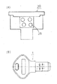
図1乃至図5は本発明の一実施例を説明するための図であり、図1は本発明のシャッター扉用シリンダー錠全体の平面図、図2は図1におけるA−A線の拡大断面図、図3はシリンダー錠の要部の説明図で、(a)は立面図、(b)はB−B線の断面図である。また図4(a)は回転プラグの側面図、同(b)は板キーの平面図、図5は要部部品を示す説明図で(a)はスライド部材、(b)はタンブラーピンの夫々の斜視図である。
【0020】
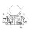
先づ図1及び図2を参照してシャッター扉用シリンダー錠全体について説明する。図において、10は平面長方形のケース本体で、その両側の短辺に切欠き10′、10′が形成されている。ケース本体10の内部には中央部の座にロータ11とその上に重ねて回転プラグ20を回転自在に収納したシリンダー30が設置され、ロータ11を挟んでロータの歯に噛合ってケースの長手方向に2本のロックレバー12、12が前記短辺の切欠き10′、10′より外方へ突出するように設けられている。
【0021】
シリンダー30に内装された回転プラグ20の鍵孔31に板キー1を差し込むと、回転プラグ20はフリーになるので板キーの操作で回転プラグを施錠方向又は解錠方向へ回わすとロータ11がこれとともに同方向に回動する。このロータの回動によりロータの歯車に噛合っているロックレバー12、12が同時に摺動しケース本体10の短辺の切欠き10′、10′より伸長方向に突出し、又は短縮方向に退入する。このロックレバー12、12の進退移動により夫々の先端に連結した鍵杆(不図示)にてシャッター扉を施錠し又は解錠するものである。このようなシャッター扉の施錠及び解錠操作は扉の内側よりは、プラグ20の内端に設けたノブ35によっても行うことができる。
【0022】
次に図3乃至図5を参照してケース本体10に設けられているシリンダー錠について説明する。シリンダー錠は板キーにより操作される回転プラグ20とこの回転プラグを回転自在に収納したシリンダー30とからなる。回転プラグ20にはその周側の一部より出没するように先端に係止用ストッパー21aを備えたU字形のスライドバー21とこのスライドバーの進退移動を規制するように配備された複数のタンブラーピン22とを具有する。回転プラグ20には、その上端にキーを差込む鍵孔31が設けられている。この鍵孔31は平面からみて長方形で、その位置は中心部に上下に貫通した縦孔として形成されている。
【0023】
スライドバー21は図3及び図5(a)に示すように一定の巾(w)と厚み(t)を有したU字形の形材で相対向した2つの支片21b、21cを設けたもので、U字部の外端部(先端)に係止用ストッパー21aを具有する。2つの支片21b、21cは間隔(s)を隔てて対向しており、この各支片にタンブラーピン22が摺動自在に挿通する係止孔24が穿設されている。このような係止孔24は図示例では両支片に前後及び上下に夫々間隔を隔てて2列に形成し、片面で4個、両面で合計8個設けることが望ましい。しかし、この係止孔24の数や配置、間隔等は多種類の組合せがあり、このため図示例の如くのみに限定されるべきでない。
【0024】
タンブラーピン22は、図3及び図5(b)に示すように、円錐形の頭部22aと胴部22bとを茎部(細軸部)22cを介して一体形成され、後部にばね受け22dを有する。頭部22aと胴部22bの直径(d)は同径であることが好ましい。また、各タンブーピンの胴部22bの長さは一定であるが、頭部22aは長さを異なる寸法に規定することが好ましい。
【0025】
回転プラグ20に上記のスライドバー21を収容するスライドバー収容孔26と、ダンブラーピン22を収容するタンブラーピン収容孔28を設ける。スライドバー収容孔26はスライドバーの係止用ストッパー21aが臨む開口部26aと、2つの支片21b、21cが嵌入してスライド案内を許容する細溝孔からなるガイド部26b、26cを有してなる。このような収容孔26にスライドバー21を収容すると、該スライドバー21は2つの支片21b、21cが鍵孔31を中間に内包した形でガイド部26b、26cに案内されて径方向にスライドし得る。スライドバー21にばね25を附勢し該ばねの弾発力でスライドバー21が外方へ押しやられて先端の係止用ストッパー21aがシリンダー30内壁の係止凹部33に係止可能となる。
【0026】
タンブラーピン収容孔28はスライドバー収容孔26と直交する向きに設けられ、夫々の収容孔26に頭部22aを中心部内向きに挿入し後端部にばね29を附勢する。ばね29は各タンブラーピン22の後端部22dと収容孔の開口部に嵌止したばね受け用プレート27との間に圧縮状態で介装される。このようにすると、タンブラーピン22は夫々中心内方へばね圧により押しやられるため、先端の頭部22aは鍵孔31内に臨みキーが差し込まれると、その板面に弾圧的に当接される。
【0027】
板キー1は、鍵孔31に嵌入しうるように断面形状が規定されているとともに、その表面2と裏面3に前記タンブラーピン22の配置に対応した部位にデインプル(凹所)4、5が形成されている。このようなデインプル4、5は板キー1の表面2と裏面3に前後及び上下に配置される。デインプル4、5の深さは夫々異なるように規定することが望ましい。また表面と裏面のデインプル4、5の対応位置はずらせるようにすることが好ましい。しかし、対応位置を一致させるようにしても差仕えない。
【0028】
次に図3を参照してシリンダー錠の作用について説明する。
【0029】
図3は解錠時の状態を示している。シリンダー錠がロックされている状態では、スライドバー21はばね25に押されて先端のストッパー(突片)21aがシリンダー30の内壁の係止凹部33に嵌入係止され、同時に各タンブラーピン22はばね29に押されて夫々の胴部22bがスライドバー21の支片21b、21cの係止孔24に嵌入している。この為スライドバー21はタンブラーピン22により後方へのスライドが阻止され且つストッパー21aと係止凹部33との係止により回転方向に対しても阻止されている。
【0030】
このロックされた状態から次に回転プラグ20の鍵孔31に板キー1を所定位置まで押し込んでセットすると、各タンブラーピン22は板キーの表面2と裏面3にタンブラーピン22の頭部22aが当り、夫々のテーパの作用でばね29を圧縮して後退させ、セット位置ではデインプル4、5により夫々の後退位置が規定され、この時タンブラーピン22の胴部22bがスライドバー21の係止孔24より抜脱して代りに茎部22cが係止孔24に臨む如くになるため、スライドバー21は後方移動への拘束が解除される。この拘束解除の状態で板キー1を解錠方向へひねるように回動させると、ストッパー21aはテーパによるカムの作用で係止凹部33より抜脱する。板キー1の操作によりプラグ20を所定角回動させるとプラグとともにロータ11が回動してロックバー12、12を退入方向へ移動させるため、シャッター扉に解錠される。
【0031】
板キー1を鍵孔33に差し込んだときに、該キーが不正なものであれば、例えばデインプルの深さ或いは位置が1つでも違ったものであればその1つのタンブラーピンは頭部又は胴部の何れかがスライドバー21の係止孔24に嵌入係止されたままになるので、スライドバーの拘束は解除されないので、シャッター扉は解錠できないことは云うまでもない。
【0032】
【発明の効果】
本発明に係るシャッター扉用シリンダー錠によると、鍵孔は偏った位置にしないで回転プラグの中心に設けることができるため、板キーによるシリンダー錠の操作を楽に円滑に行うことができるとともに、板キーの表裏両面を利用してタンブラーピンを左右に配列することでキーの種類を従来より2倍以上多く設定することが容易に可能である。また、構成、部品が少なく、簡素化できて加工工数も少なくて済み、而も耐久性の高い高品質のシャッター扉用シリンダー錠を提供することができる。
【図面の簡単な説明】
【図1】本発明のシャッター扉用シリンダー錠全体のカバーを除いた平面図である。
【図2】図1におけるA−A線の拡大断面図である。
【図3】本発明のシリンダー錠の要部の拡大図で、(a)は縦断正面図、(b)は同B−B線の横断平面図である。
【図4】(a)は回転プラグの側面図、(b)は板キーの斜視図である。
【図5】本発明の各要部の部品を示し、(a)はスライドバー、(b)はタンブラーピン夫々の斜視図である。
【図6】従来のシリンダー錠を示す説明図である。
【符号の説明】
1 板キー
10 ケース本体
11 ロータ
12 ロックレバー
20 回転プラグ
21 スライドバー
21a 係止用ストッパー
21b、21c 支片
22 タンブラーピン
24 係止孔
26 スライドバー収容孔
28 タンブラーピン収容孔
30 シリンダー
31 鍵孔
33 係止凹部[0001]
TECHNICAL FIELD OF THE INVENTION
The present invention relates to a shutter door cylinder lock incorporated in a shutter of a building or other doors.
[0002]
[Prior art]
The shutter door cylinder lock consists of a rotating plug (inner cylinder) operated by a plate key and a cylinder (outer cylinder) that rotatably stores this rotating plug in a rectangular shallow box-shaped case body attached to the shutter door. Generally, a rotor is provided at the inner end of the cylinder and a rack-tooth-type lock lever linked to move forward and backward in conjunction with the rotor (for example, see Patent Document 1).
[0003]
The above-described conventional cylinder lock is configured such that a tumbler pin is incorporated in a rotary plug, and when a plate key is inserted, the rotary plug is rotatable by being simultaneously set by side edges in the width direction of the key. Normally, tumbler pins operate according to the shape of the unevenness on both sides of the board key (edge), but if the width of the board key is large, the space is limited and the board key board Since the thickness is as thin as 1 to 2 mm, it has various problems in terms of function. As a conventional technique for solving this problem, for example, Patent Document 2 discloses a method of operating a tumbler pin by forming a dimple on a plate surface of a key using a wide surface of a plate key. I have.
[0004]
[Patent Document 1] Japanese Utility Model Registration No. 30262064 (FIG. 6)
[Patent Document 2] Japanese Patent Application Laid-Open No. 2000-314250 (6th paragraph, FIG. 1)
[0005]
A conventional cylinder lock disclosed in Patent Document 2 will be described with reference to a structural diagram shown in FIG.
[0006]
As shown in FIG. 6, the
[0007]
[Problems to be solved by the invention]
As described above, in the conventional structure shown in FIG. 6, it is difficult to operate the key smoothly and easily because the key hole is located at a position deviated to one side from the center (first problem).
[0008]
Although the key hole is biased to one side, a large space can be secured on one side, but the two rows of tumbler pins are used only for one side of the board key, and various types of high performance and high performance from the viewpoint of picking prevention and crime prevention It cannot be expected to achieve the alignment (second problem).
[0009]
The present invention makes it possible to smoothly and easily perform operations such as locking and unlocking of a shutter door by a plate key, and a configuration in which tumbler pins are arranged in front and rear and up and down can be arranged left and right. The purpose is to set.
[0010]
[Means for Solving the Problems]
A first cylinder lock for a shutter door according to the present invention includes a
[0011]
With the above configuration, operations such as locking and unlocking of the shutter door by the plate key can be easily performed, and many types of keys can be set.
[0012]
The second cylinder lock for shutter doors according to the present invention is characterized in that the
[0013]
According to the above configuration, eight tumbler pins can be arranged on the front and back sides of the plate key, four by four.
[0014]
A third shutter door cylinder lock according to the present invention is characterized in that the
[0015]
With such a configuration, the arrangement and arrangement of the tumbler pins can be further set.
[0016]
The fourth cylinder lock for a shutter door according to the present invention is characterized in that the
[0017]
According to the above configuration, it is possible to set more types of tumbler pins by changing only the head.
[0018]
DETAILED DESCRIPTION OF THE INVENTION
Hereinafter, preferred embodiments of the present invention will be described with reference to the accompanying drawings.
[0019]
1 to 5 are views for explaining one embodiment of the present invention. FIG. 1 is a plan view of an entire cylinder lock for a shutter door of the present invention, and FIG. 2 is an enlarged cross-sectional view taken along line AA in FIG. FIG. 3 and FIG. 3 are explanatory views of a main part of the cylinder lock. FIG. 3A is an elevation view, and FIG. 3B is a cross-sectional view taken along line BB. 4 (a) is a side view of the rotary plug, FIG. 4 (b) is a plan view of the plate key, FIG. 5 is an explanatory view showing essential parts, (a) is a slide member, and (b) is a tumbler pin. It is a perspective view of.
[0020]
First, the entire cylinder lock for shutter door will be described with reference to FIGS. In the figure,
[0021]
When the
[0022]
Next, the cylinder lock provided on the
[0023]
As shown in FIGS. 3 and 5A, the
[0024]
As shown in FIGS. 3 and 5B, the
[0025]
The
[0026]
The tumbler
[0027]
The cross-sectional shape of the
[0028]
Next, the operation of the cylinder lock will be described with reference to FIG.
[0029]
FIG. 3 shows a state at the time of unlocking. In a state where the cylinder lock is locked, the
[0030]
From this locked state, when the
[0031]
When the
[0032]
【The invention's effect】
According to the cylinder lock for shutter doors according to the present invention, the keyhole can be provided at the center of the rotary plug without being biased, so that the operation of the cylinder lock using the plate key can be performed smoothly and smoothly. By arranging the tumbler pins on the left and right sides using the front and back surfaces of the keys, it is possible to easily set the number of types of keys to be twice or more as compared with the conventional case. In addition, the present invention can provide a high-quality shutter door cylinder lock that is durable and requires only a small number of components and components, can be simplified and requires a small number of processing steps.
[Brief description of the drawings]
FIG. 1 is a plan view of a shutter door cylinder lock according to the present invention, from which an entire cover is removed.
FIG. 2 is an enlarged cross-sectional view taken along line AA in FIG.
FIG. 3 is an enlarged view of a main part of the cylinder lock according to the present invention, wherein FIG. 3 (a) is a longitudinal front view, and FIG. 3 (b) is a cross-sectional plan view taken along the line BB.
4A is a side view of a rotary plug, and FIG. 4B is a perspective view of a plate key.
5A and 5B are perspective views of a main part of the present invention, in which FIG. 5A is a perspective view of a slide bar, and FIG. 5B is a perspective view of a tumbler pin.
FIG. 6 is an explanatory view showing a conventional cylinder lock.
[Explanation of symbols]
1
Claims (4)
Priority Applications (1)
| Application Number | Priority Date | Filing Date | Title |
|---|---|---|---|
| JP2002361680A JP4226885B2 (en) | 2002-12-13 | 2002-12-13 | Cylinder lock for shutter door |
Applications Claiming Priority (1)
| Application Number | Priority Date | Filing Date | Title |
|---|---|---|---|
| JP2002361680A JP4226885B2 (en) | 2002-12-13 | 2002-12-13 | Cylinder lock for shutter door |
Publications (2)
| Publication Number | Publication Date |
|---|---|
| JP2004190406A true JP2004190406A (en) | 2004-07-08 |
| JP4226885B2 JP4226885B2 (en) | 2009-02-18 |
Family
ID=32760325
Family Applications (1)
| Application Number | Title | Priority Date | Filing Date |
|---|---|---|---|
| JP2002361680A Expired - Lifetime JP4226885B2 (en) | 2002-12-13 | 2002-12-13 | Cylinder lock for shutter door |
Country Status (1)
| Country | Link |
|---|---|
| JP (1) | JP4226885B2 (en) |
Cited By (3)
| Publication number | Priority date | Publication date | Assignee | Title |
|---|---|---|---|---|
| JP2011001779A (en) * | 2009-06-19 | 2011-01-06 | Gomi Seisakusho:Kk | Inner cylinder replacement type cylinder lock system |
| JP2017193832A (en) * | 2016-04-18 | 2017-10-26 | アトムリビンテック株式会社 | Pin cylinder lock |
| CN110552552A (en) * | 2019-09-30 | 2019-12-10 | 中山市基信锁芯有限公司 | Integrated lock core structure |
Families Citing this family (1)
| Publication number | Priority date | Publication date | Assignee | Title |
|---|---|---|---|---|
| JP5076226B2 (en) * | 2010-08-30 | 2012-11-21 | 優護國際企業股▲分▼有限公司 | Thin tablet |
-
2002
- 2002-12-13 JP JP2002361680A patent/JP4226885B2/en not_active Expired - Lifetime
Cited By (4)
| Publication number | Priority date | Publication date | Assignee | Title |
|---|---|---|---|---|
| JP2011001779A (en) * | 2009-06-19 | 2011-01-06 | Gomi Seisakusho:Kk | Inner cylinder replacement type cylinder lock system |
| JP2017193832A (en) * | 2016-04-18 | 2017-10-26 | アトムリビンテック株式会社 | Pin cylinder lock |
| CN110552552A (en) * | 2019-09-30 | 2019-12-10 | 中山市基信锁芯有限公司 | Integrated lock core structure |
| CN110552552B (en) * | 2019-09-30 | 2024-03-29 | 中山市基信锁芯有限公司 | Integrated lock cylinder structure |
Also Published As
| Publication number | Publication date |
|---|---|
| JP4226885B2 (en) | 2009-02-18 |
Similar Documents
| Publication | Publication Date | Title |
|---|---|---|
| US6978647B2 (en) | Pick-resistant wafer tumbler lock with sidebars | |
| KR100872338B1 (en) | A locking device | |
| CZ297025B6 (en) | Cylinder-type lock | |
| ES2806692T3 (en) | Lock system | |
| EP1112428B1 (en) | Moveable element key and key handle and lock | |
| JP4383420B2 (en) | Code lock device | |
| JP2004190406A (en) | Cylinder lock for shutter door | |
| JP3919065B2 (en) | Sidebar cylinder lock | |
| JP4476008B2 (en) | Pin tumbler tablets | |
| JP6404966B2 (en) | Lock with replaceable core | |
| JPH01299968A (en) | Side bar lock device | |
| WO2023058707A1 (en) | Locking device, unlocking key, and door | |
| JP2003184366A (en) | Variable lever tumbler lock | |
| KR200204006Y1 (en) | A lock for furniture | |
| JP6425962B2 (en) | Cabinet handle lock key and cylinder lock key | |
| JP3654848B2 (en) | Cylinder lock | |
| JP3752661B2 (en) | Disc tumbler tablets | |
| JP3992672B2 (en) | Push button lock device | |
| JP3260724B2 (en) | Variable code cylinder lock device | |
| AU753733C (en) | Moveable element key and key handle and lock | |
| AU2005202444B2 (en) | Moveable element key and key handle and lock | |
| JPH08291655A (en) | Lock device | |
| JP4195736B2 (en) | Slide lock | |
| AU782779B2 (en) | Moveable element key and key handle and lock | |
| JP2004068369A (en) | Pad lock |
Legal Events
| Date | Code | Title | Description |
|---|---|---|---|
| A621 | Written request for application examination |
Free format text: JAPANESE INTERMEDIATE CODE: A621 Effective date: 20051018 |
|
| A977 | Report on retrieval |
Free format text: JAPANESE INTERMEDIATE CODE: A971007 Effective date: 20080702 |
|
| A131 | Notification of reasons for refusal |
Free format text: JAPANESE INTERMEDIATE CODE: A131 Effective date: 20080812 |
|
| A521 | Request for written amendment filed |
Free format text: JAPANESE INTERMEDIATE CODE: A523 Effective date: 20081010 |
|
| TRDD | Decision of grant or rejection written | ||
| A01 | Written decision to grant a patent or to grant a registration (utility model) |
Free format text: JAPANESE INTERMEDIATE CODE: A01 Effective date: 20081111 |
|
| A01 | Written decision to grant a patent or to grant a registration (utility model) |
Free format text: JAPANESE INTERMEDIATE CODE: A01 |
|
| A61 | First payment of annual fees (during grant procedure) |
Free format text: JAPANESE INTERMEDIATE CODE: A61 Effective date: 20081127 |
|
| FPAY | Renewal fee payment (event date is renewal date of database) |
Free format text: PAYMENT UNTIL: 20111205 Year of fee payment: 3 |
|
| R150 | Certificate of patent or registration of utility model |
Ref document number: 4226885 Country of ref document: JP Free format text: JAPANESE INTERMEDIATE CODE: R150 Free format text: JAPANESE INTERMEDIATE CODE: R150 |
|
| FPAY | Renewal fee payment (event date is renewal date of database) |
Free format text: PAYMENT UNTIL: 20121205 Year of fee payment: 4 |
|
| R250 | Receipt of annual fees |
Free format text: JAPANESE INTERMEDIATE CODE: R250 |
|
| FPAY | Renewal fee payment (event date is renewal date of database) |
Free format text: PAYMENT UNTIL: 20121205 Year of fee payment: 4 |
|
| FPAY | Renewal fee payment (event date is renewal date of database) |
Free format text: PAYMENT UNTIL: 20131205 Year of fee payment: 5 |
|
| R250 | Receipt of annual fees |
Free format text: JAPANESE INTERMEDIATE CODE: R250 |
|
| R250 | Receipt of annual fees |
Free format text: JAPANESE INTERMEDIATE CODE: R250 |
|
| R250 | Receipt of annual fees |
Free format text: JAPANESE INTERMEDIATE CODE: R250 |
|
| R250 | Receipt of annual fees |
Free format text: JAPANESE INTERMEDIATE CODE: R250 |
|
| R250 | Receipt of annual fees |
Free format text: JAPANESE INTERMEDIATE CODE: R250 |
|
| R250 | Receipt of annual fees |
Free format text: JAPANESE INTERMEDIATE CODE: R250 |
|
| R250 | Receipt of annual fees |
Free format text: JAPANESE INTERMEDIATE CODE: R250 |
|
| R250 | Receipt of annual fees |
Free format text: JAPANESE INTERMEDIATE CODE: R250 |
|
| R250 | Receipt of annual fees |
Free format text: JAPANESE INTERMEDIATE CODE: R250 |
|
| R250 | Receipt of annual fees |
Free format text: JAPANESE INTERMEDIATE CODE: R250 |
|
| R250 | Receipt of annual fees |
Free format text: JAPANESE INTERMEDIATE CODE: R250 |
|
| EXPY | Cancellation because of completion of term |