JP2004189089A - Cab supporting structure - Google Patents
Cab supporting structure Download PDFInfo
- Publication number
- JP2004189089A JP2004189089A JP2002358852A JP2002358852A JP2004189089A JP 2004189089 A JP2004189089 A JP 2004189089A JP 2002358852 A JP2002358852 A JP 2002358852A JP 2002358852 A JP2002358852 A JP 2002358852A JP 2004189089 A JP2004189089 A JP 2004189089A
- Authority
- JP
- Japan
- Prior art keywords
- cab
- damping mechanism
- body frame
- support structure
- vehicle body
- Prior art date
- Legal status (The legal status is an assumption and is not a legal conclusion. Google has not performed a legal analysis and makes no representation as to the accuracy of the status listed.)
- Granted
Links
Images


Classifications
-
- E—FIXED CONSTRUCTIONS
- E02—HYDRAULIC ENGINEERING; FOUNDATIONS; SOIL SHIFTING
- E02F—DREDGING; SOIL-SHIFTING
- E02F9/00—Component parts of dredgers or soil-shifting machines, not restricted to one of the kinds covered by groups E02F3/00 - E02F7/00
- E02F9/08—Superstructures; Supports for superstructures
-
- B—PERFORMING OPERATIONS; TRANSPORTING
- B62—LAND VEHICLES FOR TRAVELLING OTHERWISE THAN ON RAILS
- B62D—MOTOR VEHICLES; TRAILERS
- B62D33/00—Superstructures for load-carrying vehicles
- B62D33/06—Drivers' cabs
- B62D33/0604—Cabs insulated against vibrations or noise, e.g. with elastic suspension
Abstract
Description
【0001】
【発明の属する技術分野】
この発明は、建設機械等の作業車両のキャブ支持構造に関するものであって、特にキャブに対して大きな衝撃力が作用したような場合でも安全性を確保することが可能なキャブ支持構造に関するものである。
【0002】
【従来の技術】
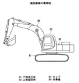
建設機械としての油圧ショベルは、一般には、図17に示すように、下部走行体81と、この下部走行体81に旋回機構を介して旋回自在に装着される上部旋回体82とを備える。そして、この上部旋回体82にはキャブ(キャビン)83が設けられると共に、このキャブ83の側方において、上部旋回体82から作業機84が突設されている。
【0003】
そして、走行中等におけるキャブ83への衝撃を緩和して乗り心地を向上させるために、従来から、キャブ83が車体フレームに対して減衰機構を介して支持されている。このように衝撃を緩和する減衰機構としては弾性体からなる防振部材等を備えたものがある(例えば、特許文献1、特許文献2、特許文献3、及び特許文献4参照)。
【0004】
特許文献1に記載のものは、図18に示すように、キャビン(キャブ)83側に取付けられる防振部材86と、この防振部材86に取付けられる位置決め部材87と、車体フレーム88側に取付けられる受け部材89とを備えている。すなわち、位置決め部材87は、その上壁87aが防振部材86にボルト部材を介して取付けられ、その下壁87bに貫孔90が設けられている。そして、上記受け部材89は、突起91を有し、この突起91が下壁87bの貫孔90に嵌合された状態で、ボルト部材を介して、下壁87bに取付けられる。これによって、キャブ83は防振部材86を介して車体フレーム88に受けられることになって、車体フレーム88側からの振動を吸収するようにしている。
【0005】
また、特許文献2に記載のものは、図19に示すように、下側部材93と、上側部材94と、この下側部材93と上側部材94とを連結する連結体95(ボルト部材103とナット部材107とからなる)とを備えている。すなわち、下側部材93は、基部96と、この基部96から立設される柱部97を有し、この基部96には、弾性体98が載置されている。また、柱部97には、上下方向に長い長孔99が設けられ、この長孔99に、楕円リング状の弾性体100が嵌合されている。そして、上側部材94は、基部101と、この基部101から立設される本体部102とを有し、本体部102に上記連結体95のボルト部材103が挿通される貫孔104が設けられている。この場合、キャブ83側の柱部105の下方開口部が上側部材94の本体部102に嵌合され、この柱部105の貫孔106、106、本体部102の貫孔104、及び下側部材93の弾性体100にボルト部材103を挿通させて、ナット部材107をこのボルト部材103に螺着している。このため、上側部材94は下側部材93の弾性体98にて受けられ、ボルト部材103が弾性体100に挿通されることによって、この弾性体98、100が防振部材となって、下側部材93が上側部材94を弾性的に受けることができ、衝撃等を緩和することができる。
【0006】
さらに、特許文献3に記載のものは、図20に示すように、車体フレーム88側に配設される一対の弾性体111、111と、この弾性体111、111を挟持する一対の受け体112、113等を備えたものである。すなわち、車体フレーム88に貫孔114が設けられ、この貫孔114に上下から弾性体111、111の一部が嵌合され、弾性体111、111を、受け体112、113にて挟んだ状態で、これらに挿通されるボルト部材115がキャブ83側に螺着されている。これによって、キャブ83は車体フレーム88に弾性的に受けられる。また、キャブ83は車体フレーム88側に変位(移動)した際には、受け体113のフランジ部116が車体フレーム88に接触して、このキャブ83のこれ以上の車体フレーム88側に変位を規制している。
【0007】
また、特許文献4に記載のものは、図21に示すように、ケース120と、このケース120内に収容されるスタッド121と、このスタッド121に連結されてケース120に収容される減衰板122等を備える。すなわち、ケース120は、上下に開口した筒状体123と、この筒状体123の下方側に配置されて上記減衰板122の収容室を形成する容器部124とからなる。また、ケース120の筒状体123に嵌合される弾性体125がスタッド121に外嵌され、容器部124には粘性液126が注入されている。そして、スタッド121から突設されたねじ部127が、キャブ側に螺着され、ケース120が車体フレーム側に取付けられる。また、ケース120の筒状体123の上端部に鍔部128が突設されていると共に、この鍔部128にストッパ129が立設されている。また、筒状体123の下端部には径方向外方へ延びる鍔部(ストッパ)130が設けられている。
【0008】
この図21に示す減衰機構では、ケース120に対して、スタッド121側が振動した場合、この振動によって粘性液126がかき回され、この粘性液126の粘性抵抗と減衰板122により、緩衝作用が作用して振動を減衰する。また、ケース120に対して、スタッド121側が傾倒した場合、キャブ側がストッパ129に当接すると共に、減衰板122がストッパ130に当接して、キャブ側がこれ以上に傾倒しないようにしている。
【0009】
【特許文献1】
特開2001−39352号公報(第2−3頁、図2)
【特許文献2】
米国特許第3868190号明細書(第3欄−4欄、図2)
【特許文献3】
特開平11−310167号公報(第32−4頁、図2)
【特許文献4】
特開平10−26172号公報(第3、図1、図3)
【0010】
【発明が解決しようとする課題】
ところで、建設機械が万一転倒した場合、あるいは岩石、樹木等が衝突した場合等において、キャブ83には大きな衝撃力が作用するが、このような衝撃力から作業者を守るために、近年においては、保護機能を有するROPS(ROLLOVER PROTECTIVE STRUCTURE)対応のキャブを使用するようになってきた。キャブ83に対して、上記のような大きな衝撃力(以下、ROPS荷重という)が作用する場合について、上記各従来例の有用性を検討した。まず、図18に示すもの(特許文献1)では、車体フレーム88からキャブ側が離れる方向に衝撃力が作用した場合、キャブ83の変位に対する規制手段がないので、キャブ83が大きく変位してしまうため、ROPS用には供し得ない。また、図19に示すもの(特許文献2)では、キャブ83側が車体フレーム88側に対して離れる方向に対して変位した場合、その変位に対して、連結体25のボルト部材103が下側部材93の弾性体100に当接して、その変位を規制することができるが、下側部材93から上側部材94が離れる方向にROPS荷重が作用した場合、この荷重は支持し得るものの、弾性体100が破損するおそれがあり、その後の使用には供し得ない。
【0011】
次に、上記図20に示すもの(特許文献3)では、キャブ83側が車体フレーム88側に接近する方向の変位に対しては、受け体113のフランジ部116が車体フレーム88に接触して、このキャブ83のこれ以上の車体フレーム88側への変位を規制している。しかしながら、逆に、キャブ側が車体フレーム88側から離れる方向方向にROPS荷重が作用した場合、この荷重は支持し得るものの、下方の弾性体111が車体フレーム88と受け体112とで圧縮され、弾性体111や受け体112が破損するおそれがあり、その後の使用には供し得ない。
【0012】
また、図21に示すもの(特許文献4)では、キャブ側が車体フレーム側に接近する方向の変位に対しては、キャブ側がストッパ129に当接して、このキャブが車体フレーム88側へそれ以上変位するのを規制している。また、キャブ側が車体フレーム側から離れる方向の変位に対しては、減衰板122がストッパ130に当接して、キャブが車体フレーム88から離れる方向へそれ以上変位するのを規制している。この図21に示すものは、ROPS対応のキャブに対して使用するのに適している。しかしながら、この場合、規制手段(ストッパ)をこの減衰機構(液体封入式マウント)自体に設けたものであるため、この減衰機構は、その構造が複雑であると共に、大型化及び重量化を招くことになって、コスト高となっていた。従って、このような特別の減衰機構を使用するROPS対応のキャブもコストの高いものにならざるを得ない。
【0013】
この発明は、上記従来の欠点を解決するためになされたものであって、その目的は、標準車等において普通に用いられている減衰機構をそのまま使用して、常態におけるキャブに対する振動や衝撃を緩和しながら、しかも建設機械が転倒した場合、あるいは岩石、樹木等が衝突した場合等に、キャブに作用する大きな衝撃力からキャブや作業者を守るための保護機能を簡素な構成で付与し得るキャブ支持構造を提供することにある。
【0014】
【課題を解決するための手段及び効果】
そこで請求項1のキャブ支持構造は、車体フレーム1に減衰機構25を介してキャブ2を支持するキャブ支持構造であって、上記減衰機構25の伸び方向に対して、キャブ2に所定の変位が生じたときにのみ、その変位を規制する規制部材26をこの減衰機構25とは別に設けたことを特徴としている。
【0015】
上記請求項1のキャブ支持構造では、減衰機構25にて、車体フレーム1に対してキャブ2を支持するので、常態においてキャブ2に作用する振動や衝撃を緩和できる。また、建設機械が転倒した場合、あるいは岩石、樹木等が衝突した場合等に、キャブ2に大きな衝撃力が作用して、所定の変位が生じたときには、規制部材26にてその変位を規制し、キャブ剛性を向上して、キャブ損傷等の事故を防止することができる。そして、このキャブ支持構造では、規制部材26が減衰機構25と別個に設けられるものであるので、標準車等において普通に用いられている減衰機構25をそのまま使用し、規制部材26を新た追加すればよい。このため、キャブ剛性向上のために高価な特別な減衰機構を使用する必要がなく、そのための例えばROPS仕様車を低コストにて提供することができる。
【0016】
請求項2のキャブ支持構造は、上記規制部材26は、キャブ2側に取付けられるキャブ側部材を有し、常態において、このキャブ側部材が上記車体フレーム1側と非干渉関係にあるように、配置されることを特徴としている。
【0017】
請求項2のキャブ支持構造では、常態においてこのキャブ側部材が上記車体フレーム1側と非干渉関係にあるので、この常態において、減衰機構25と規制部材26とが非干渉関係となる。このため、このキャブ支持構造が使用された油圧ショベル等の建設機械において、通常の走行時や作業時には、規制部材26は、減衰機構25の作動状態に全く影響を及ぼさないので、例えば標準車と全く同様に、減衰機構25にてキャブ2に対する振動や衝撃を緩和でき、乗り心地性を悪くすることがない。
【0018】
請求項3のキャブ支持構造は、上記規制部材26は、上記減衰機構25のストロークエンド前にキャブ2の変位を規制することを特徴としている。
【0019】
上記請求項3のキャブ支持構造では、減衰機構25のストロークエンド前にキャブ2の変位を規制部材26にて規制するので、減衰機構25の破損を確実に回避することができ、減衰機構25の耐久性向上を図ることができる。すなわち、減衰機構25に対して、これを破損させるROPS荷重等の過大荷重が作用しないので、キャブ支持構造としては、耐久性に優れたものとなって、長期に渡って乗り心地がよいキャブ2となる。
【0020】
請求項4のキャブ支持構造は、上記規制部材26を、キャブ2の支柱10と車体フレーム1との間に配置したことを特徴としている。
【0021】
上記請求項4のキャブ支持構造では、規制部材26を、キャブ2の支柱10と車体フレーム1との間に配置したことにより、規制部材26によるキャブ2の支持剛性を向上できる。これにより、ROPS荷重等の過大荷重が作用したときに、キャブ損傷等の事故を一段と確実に防止することができる。
【0022】
請求項5のキャブ支持構造は、上記車体フレーム1に作業機が配置される場合において、上記規制部材26が少なくとも反作業機側に設けられることを特徴としている。
【0023】
上記請求項5のキャブ支持構造のように、車体フレーム1に作業機が配置されている場合には、キャブ2に対して、作業機がガードとして機能することになるので、作業機側からキャブ2にROPS荷重等の過大荷重が作用する機会は少なくなる。これに対して、反作業機側において、ROPS荷重等の過大荷重が作用する機会は、それよりも多い。このため、反作業機側に規制部材26を設ければ、その機能を有効に発揮できる。また、作業機側の規制部材26を省略すれば、コストダウンを図ることができる。
【0024】
請求項6のキャブ支持構造は、上記キャブ2は、後方側が前方側よりも剛性が大きく設定される場合において、上記規制部材26が少なくともキャブ後方側に設けられることを特徴としている。
【0025】
上記請求項6のキャブ支持構造では、上記キャブ2は、後方側が前方側よりも剛性が大きく設定される。これは、前方側においては、視野を確保するためにキャブ前方側の支柱等を細くする必要があり、また後方側においては、支柱等を太くして剛性を大きく設定するのが好ましいからである。その一方、作業者は前方に対しては監視することができるので、前方側でのROPS荷重等の過大荷重の作用は、ある程度、回避することができるが、後方は監視しにくく、後方側において、ROPS荷重等の過大荷重が作用する機会が多い。従って、キャブ後方側に、規制部材26を設ければ、その機能を有効に発揮できる。また、キャブ前方側の規制部材26を省略すれば、コストダウンを図ることができる。さらに、支柱等を太くして剛性を大きくすれば、このキャブ後方側における規制部材26の取付け作業が容易となる利点もある。
【0026】
【発明の実施の形態】
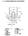
次に、この発明のキャブ支持構造の具体的な実施の形態について、図面を参照しつつ詳細に説明する。図1はこのキャブ支持構造の拡大断面図を示し、このキャブ支持構造は、油圧ショベル等の建設機械に使用され、上部旋回体の車体フレーム1に対してキャブ(運転室)2を浮かせた状態で支持するものである。
【0027】
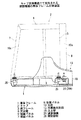
キャブ2は、図2から図4に示すように床フレーム3の4隅からは支柱10a、10b、10c、10dが立設されて、ROPS対応のキャブとされている。そして、天井側には天井壁4が設けられ、側面側には側面パネル5、5が設けられ、前面側には前面パネル7が設けられ、後面側には後面パネル8が設けられている。この場合、後方側の支柱10a、10bが前方側の支柱10c、10dよりも(太い)大型のものを使用している。すなわち、図4に示すように、後方側の支柱10a、10bの前後方向寸法を、前方側の支柱10c、10dの前後方向寸法よりも大きく設定すると共に、後方側の支柱10a、10bの左右方向の寸法(厚さ寸法)を、前方側の支柱10c、10dの厚さ寸法よりも大きく設定している。これは、前面パネル7及び側面パネル5、5に窓部を設けているので、前方側の支柱10c、10dを細くして視野を確保するためである。これによって、このキャブ2は、後方側が前方側よりも剛性が大きく設定される。
【0028】
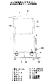
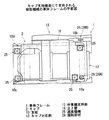
また、上部旋回体の車体フレーム1は、図5に示すように、上記キャブ2がこのキャブ支持構造を介して支持されるキャブ対応部12と、上部旋回体に付設される作業機(図示省略)が取付けられる作業機支持部13とを有する。キャブ対応部12は、前支持枠14と、後支持枠15と、前支持枠14と後支持枠15とを連結する側枠16等を備え、作業機支持部13は、基板17と、この基板17に立設される一対の立上壁18、19等を備える。
【0029】
前支持枠14は、前面壁部14aと上面壁部14bとを有し、その上面壁部14bには、後述する減衰機構25(図1参照)を装着するための貫孔20、20が設けられ、作業機支持部13側の端部が基板17に固定され、反作業機側の端部が側枠16に固定されている。また、後支持枠15は、上壁15aと、この上壁15aの前端縁及び後端縁から垂下される脚部15b、15bとからなり、前支持枠14と同様、作業機支持部13側の端部が基板17に固定され、反作業機側の端部が側枠16に固定されている。そして、この後支持枠15の上壁15aに、減衰機構25を装着するための貫孔21、21及び後述する規制部材26(図1参照)を装着するために貫孔22が設けられている。なお、このキャブ対応部12においては、前支持枠14と後支持枠15の間には、中間枠体23が配設されている。
【0030】
次に、キャブ支持構造は、車体フレーム1に対して弾性的にキャブ2を支持する減衰機構25と、減衰機構25の伸び方向に対してキャブ2に所定の変位が生じたときにのみ、その変位を規制する規制部材26とを備えるものであって、キャブ2を上記したように、車体フレーム1に対して浮かした状態で支持する。
【0031】
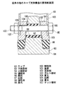
減衰機構25は、図1に示すように、ケース27と、このケース27内に収容される第1の減衰板28と、その第1の減衰板28を支持するスタッド29等を備える。また、第1の減衰板28は、上壁28aと、垂下壁28bとからなり、上壁28aがスタッド29の下端にボルト結合されている。そして、スタッド29には弾性体30が外嵌され、この弾性体30の下面がケース27内の第2の減衰板31にて受けられている。また、弾性体30の下面には凹所が形成されている。これらによって、ケース27の内部は、A室33aとB室33bとC室33cとに仕切られている。さらに、第1の減衰板28の上壁28aとケース27の底壁との間にコイルスプリング32が配設され、A室33aとB室33bとC室33cとにシリコンオイル等の粘性液が封入されている。この際、A室33aとB室33bとが、第1の減衰板28の垂下壁28bとケース27の内面との間の隙間H1を介して連通され、B室33bとC室33cとが、第2の減衰板31の内周側に設けられる隙間H2を介して連通されている。
【0032】
そして、この減衰機構25はそのケース27の上方開口部に外鍔部35が形成され、前支持枠14に装着される減衰機構25では、上面壁部14bの貫孔20に嵌合されてこの外鍔部35が上面壁部14bの上面に係止し、その状態で、ボルト部材(図示省略)を介して外鍔部35が上面壁部14bに締着され、後支持枠15に装着される減衰機構25では、上壁15aの貫孔21に嵌合されてこの外鍔部35が上壁15aの上面に係止し、その状態で、ボルト部材(図示省略)を介してこの外鍔部35が上壁15aに締着される。また、スタッド29は、その上端部にねじ軸部(図示省略)が設けられ、このねじ軸部を介してキャブ2の床フレーム3に締着される。
【0033】
このように、キャブ2は底フレーム3の裏面の4隅において減衰機構25を介して車体フレーム1に支持され、車体フレーム1側からの衝撃等が緩和される。すなわち、車体フレーム1に対してキャブ2が離れる方向に変位した場合、スタッド29が上方へ引っ張られ、粘性液はB室33bから隙間H1を介してA室33aへ流れ、C室33cから隙間H2を介してB室33bへ流れ、この際の抵抗により振動の減衰力が得られる。さらに、上方向に大きな負荷が作用する場合は、第2の減衰板31が第1の減衰板28を受け止めて弾性体30を撓ませてその衝撃を緩衝する。
【0034】
また、逆に、車体フレーム1に対してキャブ2が近づく方向に変位した場合、スタッド29が下方へ押され、粘性液はA室33aから隙間H1を介してB室33bへ流れ、B室33bから隙間H2を介してC室33cへ流れ、この際の抵抗により振動の減衰力が得られる。さらに、下方向に大きな負荷が作用する場合は、床フレーム3の下面が弾性体30の上面に当接してこの弾性体30を撓ませてその衝撃を緩衝する。この際、コイルスプリング32にて第1の減衰板31を弾性的に受けることができ、その衝撃を緩衝することができる。
【0035】
しかしながら、建設機械が転倒した場合、あるいは岩石、樹木等が衝突した場合等に、キャブ2に大きな衝撃力する。そこで、このキャブ支持構造には、この衝撃力からキャブ2や作業者を守るための保護機能として作用する上記規制部材26が設けられている。そして、この実施の形態においては、規制部材26をキャブ後方側に2個だけ配置している。また、反作業機側の規制部材26と、作業機側の規制部材26とではその構成を相違させている。
【0036】
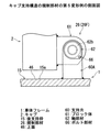
反作業機側の規制部材26(この場合、第1規制部材26Aと呼ぶ)は、図1に示すように、軸部材36と、この軸部材36に外嵌される円筒状スペーサ37と、軸部材36が挿通されて円筒状スペーサ37の下方に配置されるストッパ38等を備える。軸部材36は、軸部36aと頭部36bとからなるボルト部材で構成され、その軸部36aがキャブ2の床フレーム3に締着される。この際、円筒状スペーサ37は、上壁15aの貫孔22に遊嵌状に嵌合される。そして、円筒状スペーサ37と軸部材36の頭部36bとの間にストッパ38が介在されている。
【0037】
すなわち、円筒状スペーサ37の外径寸法が、上壁15aの貫孔22の内径寸法よりも小さく設定され、さらに、円筒状スペーサ37の内径寸法が、軸部材36の軸部36aの外径寸法よりも大きく設定されている。また、ストッパ38は、中心孔38aを有する円板体からなり、その中心孔38aの径寸法が軸部材36の軸部36aの外径寸法よりも僅かに大きく設定されている。
【0038】
さらに、上壁15aの裏面(下面)40には受け板41が付設されている。この受け板41はリング体からなり、その中心孔41aの軸心を上壁15aの貫孔22の軸心と一致させると共に、中心孔41aの孔径を貫孔22の孔径と略同一に設定している。この際、上記ストッパ38の外径寸法は、受け板41の中心孔41aの孔径よりも大きく、受け板41の外径寸法よりも小さく設定されている。
【0039】
そして、キャブ2が上記4つの減衰機構25・・にて受けられて、車体フレーム1から振動や衝撃が発生していない状態において、ストッパ38の上面42と受け板41の下面43との間に隙間Sが形成され、円筒状スペーサ37の外周面と上壁15aの貫孔22の内周面及び受け板41の中心孔41aの内周面との間に隙間S1が形成される。
【0040】
従って、キャブ2が車体フレーム1から離れる方向へ変位した場合、この第1規制部材26Aとしては、ストッパ38の上面42が受け板41の下面43に当接するまで、その変位を許容する。また、キャブ2が車体フレーム1に近づく方向へ変位した場合、この第1規制部材26Aとしては、キャブ2の底フレーム3の下面が上壁15aの上面46に当接するまで、その変位を許容する。さらに、キャブ2が車体フレーム1に対して水平方向に変位した場合、スペーサ37の外周面が貫孔22の内周面等に当接するまで許容する。このため、キャブ2側に取付けられるキャブ側部材(円筒状スペーサ37、ストッパ38、及び軸部材36等)が、常態において車体フレーム1側と非干渉関係にあるように、上記隙間S、S1の寸法を設定する。これによって、作業機による通常の作業時や走行時においては、この第1規制部材26Aは減衰機構25による衝撃等の吸収機能に対して干渉しないようにする。
【0041】
この際、キャブ2が車体フレーム1から離れる方向へ変位する場合には、第1規制部材26Aとしては、減衰機構25の伸び方向のストロークエンド(弾性体30やコイルスプリング32が弾性限界)を越えないように規制する。すなわち、減衰機構25のストロークエンドを越える直前において、ストッパ38を受け板41に当接させるように上記隙間Sを設定するものであって、減衰機構25のストロークエンド越えない範囲においては、この第1規制部材26Aとしては減衰機構25による衝撃等の吸収機能に対して干渉しない。
【0042】
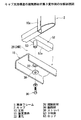
次に、作業機側の規制部材26(この場合、第1変形例として、第2規制部材26Bと呼ぶ)は、図6と図7に示すように、作業機支持部13の一方の立上壁18に支持される軸部材47と、キャブ後方側の作業機側の支柱10bに固着される受け体48とからなる。軸部材47は、軸部47aと頭部47bとからなるボルト部材から構成され、立上壁18のねじ孔49に作業機側から螺着させ、その軸部47aを支柱10b側へ突出させる。また、受け体48は、水平壁48aと鉛直壁48bとを有する断面L字状体からなり、その支柱10b側の端面54が支柱10bに溶接等の結合手段にて結合されている。そして、上記4つの減衰機構25・・にて受けられて、車体フレーム1から振動や衝撃が発生していない状態において、立上壁18から突出した軸部47aの突出部50が、受け体48の水平壁48aよりも上方に位置すると共に、鉛直壁48bよりも前方に位置している。すなわち、この場合も、常態において、キャブ側部材である受け体48が車体フレーム1側の部材である軸部材47と非干渉状態にように設定する。
【0043】
また、キャブ2が車体フレーム1から離れる方向へ変位した場合、この作業機側の第2規制部材26Bとしては、受け体48の水平壁48aが立上壁18から突出した軸部47aの突出部50に当接するまで、その変位を許容するので、この場合も、減衰機構25の伸び方向のストロークエンド(弾性体30やコイルスプリング32が弾性限界)を越えないように規制する。すなわち、減衰機構25のストロークエンド直前に、受け体48の水平壁48aを軸部47aの突出部50に当接させるように設定する。また、この第2規制部材26Bでは、キャブ2に後方側から荷重(負荷)を受けた場合、受け体48の鉛直壁48bが軸部47aの突出部50に当接することによって、キャブ2が回転したりすることを規制することができる。
【0044】
ところで、この作業機側の第2規制部材26Bを図6と図7に示す構造としたのは、この装着位置において作業機支持部13の基板17が下方に位置するため、図1に示すような第1規制部材26Aの装着が困難であるからである。このため、この位置においても、上記第1規制部材26Aが装着可能であれば、この第2規制部材26Bを使用することなく、第1規制部材26Aを使用してもよい。
【0045】
このように、このキャブ支持構造では、減衰機構25・・にて、車体フレーム1に対して弾性的にキャブ2を支持するので、キャブ2に対する振動や衝撃を緩和できる。この際、常態においては、規制部材26A、26Bと減衰機構25、25とは非干渉状態にあるので、規制部材26A、26Bによる規制が行われず、規制部材26A、26Bは、減衰機構25の作動状態に全く影響を及ぼさない。このため、常態においては、減衰機構25にてキャブ2に対する振動や衝撃を緩和でき、乗り心地性を悪くすることがない。
【0046】
ところが、建設機械が転倒した場合、あるいは岩石、樹木等が衝突した場合等に、キャブ2に大きな衝撃力(ROPS荷重等)が作用して、所定の変位が生じたときには、規制部材26A、26Bにてその変位を規制し、キャブ剛性を向上して、キャブ損傷等の事故を防止することができる。しかも、減衰機構25の伸び方向のストロークエンドに達する直前に、その変位を上記規制部材26A、26Bにて規制することができる。このため、減衰機構25の破損を確実に回避することができ、減衰機構25の耐久性向上を図ることができる。すなわち、減衰機構25に対して、これを破損させるROPS荷重等の過大荷重が作用しないので、キャブ支持構造としては、耐久性に優れたものとなって、長期に渡って乗り心地がよいキャブ2となる。そして、このキャブ支持構造では、規制部材26A、26Bが減衰機構25と別個に設けられるものであるので、標準車等において普通に用いられている減衰機構25をそのまま使用し、規制部材26を新た追加すればよい。このため、ROPS仕様車であっても、キャブ剛性向上のために高価な特別な減衰機構を使用する必要がなく、ROPS仕様車を低コストにて提供することができる。ところで、上記実施形態では、作業者は前方に対しては監視することができるので、前方側でのROPS荷重等の作用は、ある程度、回避することができるが、後方は監視しにくく、そのため、後方側において、ROPS荷重等の過大荷重が作用する機会が多い。従って、この実施形態のように、キャブ後方側に規制部材26A、26Bを設ければ、その機能を有効に発揮できる。また、キャブ後方側に規制部材26A、26Bを設ければ、キャブ保護機能を有効に発揮できるので、キャブ前方側の規制部材26を省略することができ、省略すれば、コストダウンを図ることができる。さらに、この実施形態では、後方側において、支柱10a、10b等を太くして剛性を大きくしているので、このキャブ後方側における規制部材26A、26Bの取付け作業が容易となる利点もある。
【0047】
ところで、反作業機側の前方側の減衰機構25の近傍に規制部材26(26A)を設けてもよい。すなわち、反作業機側に規制部材26、26を設けるようにする。これは、このように作業機が作業機支持部13に設けられれば、図3の矢印の方向にキャブ2が傾倒する方向に過大荷重が作用しやすいからである。すなわち、車体フレーム1に作業機が配置されている場合には、キャブ2に対して、作業機がガードとして機能することになるので、作業機側からキャブ2にROPS荷重等の過大荷重が作用する機会は少なくなる。これに対して、反作業機側において、ROPS荷重等の過大荷重が作用する機会は、それよりも多い。そのため、反作業機側に規制部材26、26を設ければ、変位を規制する機能を有効に発揮できる。この場合、反作業機側に規制部材26、26を設けることにより、キャブ保護機能を有効に発揮できるので、作業機側の後方側の第2規制部材26Bを省略することができ、省略すれば、コストダウンを図ることができる。
【0048】
次に図8は、第2変形例としての規制部材26Cを示し、この場合、支柱10aにこの規制部材26Cが支持されている。すなわち、スペーサ37の上端が、支柱10aの底壁11に溶接等の接合手段にて、固着され、支柱10aの底壁11の内面側に配置されるナット部材51に軸部材36の軸部36aが螺着されている。この場合も、スペーサ37は、その外径が上壁15aの貫孔22の孔径よりも小さく設定され、この貫孔22に遊嵌状は挿通されている。従って、この場合も、ストッパ38の上面42と、後支持枠15の下面40との間に隙間Sが設けられると共に、スペーサ37の外周面と上壁15aの貫孔22の内周面との間に隙間S1が設けられる。
【0049】
また、キャブ2が図9に示すように下枠体52を有する場合、この図9のように第3変形例を示す規制部材26Dをこの下枠体52の左右方向バー52aに付設するようにしてもよい。この場合、図10に示すように、左右方向バー52aにロッド53を溶接等の接合手段にて、固着し、このロッド53に軸部材36の軸部36aを螺着して、ストッパ38をロッド53に装着する。この場合も、このロッド53の外径寸法を上壁15aの貫孔22の径寸法よりも小さく設定し、ストッパ38の上面42と上壁15aの下面40との間に、隙間Sが形成され、ロッド53の外周面と貫孔22の内周面との間に隙間S1が形成されるようにする。
【0050】
従って、この図8と図10に示す規制部材26C、26Dにおいても、常態においてキャブ側部材(スペーサ37、軸部材36、ロッド53等)が上記車体フレーム1側と非干渉関係にあるように設定され、通常の走行時や作業時には、減衰機構25の衝撃緩和機能の規制が行われず、乗り心地性を悪くすることがない。しかも、キャブ2にROPS荷重等の過大荷重が作用して、所定の変位が生じたときには、ストッパ38の上面42が上壁15aの下面40に当接して、この変位を規制し、キャブ剛性を向上して、キャブ損傷等の事故を防止することができる。また、図8に示すものでは、支柱10aに規制部材26が支持されているので、規制部材26によるキャブ2の支持剛性を向上できる。これにより、ROPS荷重等の過大荷重が作用したときに、キャブ損傷等の事故を一段と確実に防止することができる。なお、図8と図10等においては、図1において使用した受け板41が使用されていないが、もちろんこの図8等においても受け板41を使用してもよく、逆に図1において受け板41を使用しなくてもよい。
【0051】
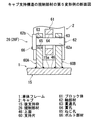
次に、図11と図12に示す第4変形例としての規制部材26Eは、車体フレーム1の上壁15aの上面46から立設されるロッド55と、このロッド55の上方からストッパ38を挟んだ状態で螺着される軸部材36と、キャブ2側に付設される受け片56とを備える。すなわち、受け片56は、底壁部56aと、この底壁部56aの両端から立設される三角形状の立上壁部56b、56bとからなり、底壁部56aには貫孔57が設けられている。この場合、ロッド55の外径が貫孔57の径寸法よりも小さく設定され、ロッド55が貫孔57に遊嵌状に挿入されている。
【0052】
そして、車体フレーム1から振動や衝撃が発生していない状態において、ストッパ38の下面58と受け片56の上面59との間に、隙間Sが形成され、ロッド55の外周面と受け片56の底壁部56aの貫孔57の内周面との間に、隙間S1が形成されるようにする。これによって、この図11と図12に示す規制部材26Eにおいても、常態においてキャブ側部材(受け片56等)が上記車体フレーム1側の部材(ロッド55等)と非干渉関係にあるように設定され、通常の走行時や作業時には、支持対25の衝撃緩和機能の規制が行われず、しかも、キャブ2にROPS荷重等の過大荷重が作用して、所定の変位が生じたときには、受け片56の底壁部56aの上面59がストッパ38の下面58に当接して、この変位を規制し、キャブ剛性を向上して、キャブ損傷等の事故を防止することができる。
【0053】
また、図13から図15に示す第5変形例としての規制部材26Fは、車体フレーム1の上壁15aの上面46から立設される一対の支持片60A、60Bと、この支持片60A、60B間に介在されるブロック体61と、ブロック体61が介在された状態で支持片60A、60Bに挿通される軸部材62とを備える。すなわち、ブロック体61はキャブ2側に固着され、軸部材62の軸部62aが挿通される貫孔64が形成されている。貫孔64は、その孔径が軸部材62の軸部62aの外径よりも大きく設定され、軸部材62の軸部62aが遊嵌状に挿通されている。また、支持片60A、60Bにも、軸部材62の軸部62aが挿通される貫通孔63、63が形成されている。この貫通孔63の孔径は軸部材62の軸部62aの外径寸法よりも僅かに大きい程度である。また、軸部材62は、上記軸部62aと、頭部62bとからなり、図15に示すように、軸部62aが、一方の支持片60Aの貫通孔63、ブロック体61の貫孔64、及び他方の支持片60Bの貫通孔63に挿通された状態では、ロックされる。すなわち、一方の支持片60Aにねじ孔65を設け、軸部材62の頭部62bに設けられた貫通孔を介して、このねじ孔65にボルト部材66を螺着する。
【0054】
これによって、この図13から図15に示す規制部材26Fにおいても、常態においてキャブ側部材(ブロック体61等)が上記車体フレーム1側と非干渉関係にあるように設定され、通常の走行時や作業時には、支持対25の衝撃緩和機能の規制が行われない。しかも、キャブ2にROPS荷重等の過大荷重が作用して、所定の変位が生じたときには、ブロック体61の貫孔64の内周縁が軸部材62の軸部62aに当接して、この変位を規制することができ、キャブ剛性を向上して、キャブ損傷等の事故を防止することができる。
【0055】
また、図16(a)に示す第6変形例としての規制部材26Gは、車体フレーム1の上壁15aの上面46から立設される受け片67と、キャブ2側の支持体68とを備える。受け片67は、上壁15aの上面46に取付けられる下片部67aと、この下片部67aから上下方向に延びる立上片部67bと、この立上片部67bの上端から水平方向へ延びる上片部67cとからなる。なお、下片部67aを上壁15aの上面46に取付ける場合、ボルト・ナット結合であっても、溶接等であってもよい。また、支持体68は、水平壁68aと、鉛直壁68bとからなる断面L字状の型材でもって構成され、車体フレーム1から振動や衝撃が発生していない状態において、受け片67の上片部67cの下面70と、支持体68の水平壁68aの上面71との間に、隙間Sが形成されるようにする。また、この隙間Sが形成される状態では、受け片67の立上片部67bの内面と支持体68の鉛直壁68bの先端縁との間に隙間S2を設けるようにする。
【0056】
これによって、この図16(a)に示す規制部材26Gにおいても、常態においてキャブ側部材(支持体68等)が上記車体フレーム1側の部材(受け片67等)と非干渉関係にあるように設定され、通常の走行時や作業時には、支持対25の衝撃緩和機能の規制が行われない。しかも、キャブ2にROPS荷重等の過大荷重が作用して、所定の変位が生じたときには、支持体68の水平壁68aの上面71が受け片67の上片部67cの下面70に当接して、この変位を規制することができ、キャブ剛性を向上して、キャブ損傷等の事故を防止することができる。また、支持体68としては、図16(b)のように、上壁72aと、下壁72bと、上壁72aと下壁72bとを連結する連結壁72cとからなる断面コの字状の型材でもって構成してもよい。この際も、受け片67の上片部67cの下面70と、支持体68の上壁72aの上面73との間に隙間Sが形成されると共に、受け片67の立上片部67bと、支持体68の連結壁72cとの間に隙間S2が形成されるようにすればよい。
【0057】
以上にこの発明の具体的な実施の形態について説明したが、この発明は上記形態に限定されるものではなく、この発明の範囲内で種々変更して実施することができる。例えば、規制部材26を設ける位置としては、キャブ2の床フレーム3の4隅全てであっても、4隅以外であってもよく、さらには、規制部材26の数としては4個以上であってもよい。また、減衰機構25としては、図例のものに限るものではなく、各種の液体封入式マウントや非液体封入式マウント等を使用できる。さらに、規制部材26としては、減衰機構25のストロークエンド前にキャブ2の変位を規制することが望ましいので、使用する減衰機構25(マウント)のストロークエンドに応じて、規制する変位量を任意に変更することができるが、もちろん、大きな衝撃力からキャブ2を守る保護機能を発揮できれば、減衰機構25のストロークエンドを越えて規制するものであってもよい。なお、このキャブ支持構造が使用される機械としては、油圧ショベル以外にも、ホイールローダやブルドーザ等の各種の建設機械であっても、さらには、キャブ支持構造を必要とする各種の農業機械等であってもよい。また、このキャブ支持構造としては、ROPS対応のキャブに対して使用するのが好ましいが、もちろんROPS対応のキャブでない標準車のキャブに対して使用してもよい。
【図面の簡単な説明】
【図1】この発明のキャブ支持構造の実施形態を示す拡大断面図である。
【図2】上記キャブ支持構造にて支持される建設機械の車体フレームの側面図である。
【図3】上記キャブ支持構造にて支持される建設機械の車体フレームの背面図である。
【図4】上記キャブ支持構造にて支持される建設機械の車体フレームの平面図である。
【図5】上記キャブ支持構造にて支持される建設機械の車体フレームの斜視図である。
【図6】上記キャブ支持構造の作業機側の規制部材の平面図である。
【図7】上記キャブ支持構造の作業機側の規制部材の断面図である。
【図8】上記キャブ支持構造の規制部材の第2変形例の断面図である。
【図9】上記キャブ支持構造の規制部材の第3変形例の分解斜視図である。
【図10】上記キャブ支持構造の規制部材の第3変形例の断面図である。
【図11】上記キャブ支持構造の規制部材の第4変形例の分解斜視図である。
【図12】上記キャブ支持構造の規制部材の第4変形例の断面図である。
【図13】上記キャブ支持構造の規制部材の第5変形例の分解斜視図である。
【図14】上記キャブ支持構造の規制部材の第5変形例の側面図である。
【図15】上記キャブ支持構造の規制部材の第5変形例の断面図である。
【図16】上記キャブ支持構造の規制部材の第6変形例を示し、(a)の断面図であり、(b)は他の減衰機構を使用した場合の断面図である。
【図17】建設機械の簡略図である。
【図18】従来のキャブ支持構造の要部断面図である。
【図19】従来の他のキャブ支持構造の要部断面図である。
【図20】従来の別のキャブ支持構造の要部断面図である。
【図21】従来のさらに別のキャブ支持構造の要部断面図である。
【符号の説明】
1 車体フレーム
2 キャブ
25 減衰機構
26 規制部材[0001]
BACKGROUND OF THE INVENTION
The present invention relates to a cab support structure for a work vehicle such as a construction machine, and more particularly to a cab support structure capable of ensuring safety even when a large impact force acts on the cab. is there.
[0002]
[Prior art]
As shown in FIG. 17, a hydraulic excavator as a construction machine generally includes a
[0003]
Conventionally, the
[0004]
As shown in FIG. 18, the device described in
[0005]
Further, as shown in FIG. 19, the device described in
[0006]
Further, as described in
[0007]
As shown in FIG. 21, the device described in Patent Document 4 includes a
[0008]
In the damping mechanism shown in FIG. 21, when the
[0009]
[Patent Document 1]
JP 2001-39352 A (page 2-3, FIG. 2)
[Patent Document 2]
U.S. Pat. No. 3,868,190 (columns 3-4, FIG. 2)
[Patent Document 3]
Japanese Patent Laid-Open No. 11-310167 (page 32-4, FIG. 2)
[Patent Document 4]
Japanese Patent Laid-Open No. 10-26172 (third, FIG. 1, FIG. 3)
[0010]
[Problems to be solved by the invention]
By the way, when a construction machine falls down or when rocks, trees, etc. collide, a large impact force acts on the
[0011]
Next, in the case shown in FIG. 20 (Patent Document 3), the
[0012]
Further, in the case shown in FIG. 21 (Patent Document 4), for displacement in a direction in which the cab side approaches the vehicle body frame side, the cab side contacts the
[0013]
The present invention has been made to solve the above-mentioned conventional drawbacks, and its purpose is to use a damping mechanism normally used in a standard vehicle or the like as it is to reduce vibrations and impacts on the cab in a normal state. While mitigating, when a construction machine falls down, or when rocks, trees, etc. collide, it can be provided with a protective function to protect the cab and workers from a large impact force acting on the cab with a simple configuration The object is to provide a cab support structure.
[0014]
[Means and effects for solving the problems]
Accordingly, the cab support structure according to
[0015]
In the cab support structure according to the first aspect, since the
[0016]
In the cab support structure according to
[0017]
In the cab support structure according to the second aspect, since the cab side member is in a non-interfering relationship with the
[0018]
The cab support structure according to
[0019]
In the cab support structure according to the third aspect, the displacement of the
[0020]
The cab support structure according to claim 4 is characterized in that the regulating
[0021]
In the cab support structure according to the fourth aspect, the
[0022]
The cab support structure according to
[0023]
When the working machine is arranged on the
[0024]
The cab support structure according to claim 6 is characterized in that, when the rear side of the
[0025]
In the cab support structure according to the sixth aspect, the
[0026]
DETAILED DESCRIPTION OF THE INVENTION
Next, specific embodiments of the cab support structure of the present invention will be described in detail with reference to the drawings. FIG. 1 shows an enlarged cross-sectional view of the cab support structure. The cab support structure is used in a construction machine such as a hydraulic excavator, and the cab (operator's cab) 2 is floated with respect to a
[0027]
As shown in FIGS. 2 to 4, the
[0028]
Further, as shown in FIG. 5, the
[0029]
The
[0030]
Next, the cab support structure includes a damping
[0031]
As shown in FIG. 1, the damping
[0032]
The damping
[0033]
Thus, the
[0034]
Conversely, when the
[0035]
However, a large impact force is applied to the
[0036]
As shown in FIG. 1, the anti-work machine side regulating member 26 (referred to as the first regulating
[0037]
That is, the outer diameter dimension of the
[0038]
Further, a receiving
[0039]
When the
[0040]
Therefore, when the
[0041]
At this time, when the
[0042]
Next, as shown in FIGS. 6 and 7, the work machine side regulating member 26 (in this case, referred to as a second regulating
[0043]
When the
[0044]
By the way, the
[0045]
Thus, in this cab support structure, the
[0046]
However, when the construction machine falls or when a rock, a tree, or the like collides, a large impact force (ROPS load or the like) acts on the
[0047]
Incidentally, a restricting member 26 (26A) may be provided in the vicinity of the front-
[0048]
Next, FIG. 8 shows a regulating member 26C as a second modified example, and in this case, the regulating member 26C is supported by the
[0049]
Further, when the
[0050]
Accordingly, the regulating
[0051]
Next, a regulating
[0052]
In a state where no vibration or impact is generated from the
[0053]
Further, a restricting
[0054]
Accordingly, also in the restricting
[0055]
A restricting member 26G as a sixth modified example shown in FIG. 16A includes a receiving
[0056]
Accordingly, also in the regulating member 26G shown in FIG. 16A, the cab side member (
[0057]
Although specific embodiments of the present invention have been described above, the present invention is not limited to the above embodiments, and various modifications can be made within the scope of the present invention. For example, the
[Brief description of the drawings]
FIG. 1 is an enlarged cross-sectional view showing an embodiment of a cab support structure of the present invention.
FIG. 2 is a side view of a body frame of a construction machine supported by the cab support structure.
FIG. 3 is a rear view of a vehicle body frame of a construction machine supported by the cab support structure.
FIG. 4 is a plan view of a vehicle body frame of a construction machine supported by the cab support structure.
FIG. 5 is a perspective view of a body frame of a construction machine supported by the cab support structure.
FIG. 6 is a plan view of a regulating member on the work machine side of the cab support structure.
FIG. 7 is a cross-sectional view of a regulating member on the work machine side of the cab support structure.
FIG. 8 is a cross-sectional view of a second modification of the regulating member of the cab support structure.
FIG. 9 is an exploded perspective view of a third modification of the regulating member of the cab support structure.
FIG. 10 is a cross-sectional view of a third modification of the regulating member of the cab support structure.
FIG. 11 is an exploded perspective view of a fourth modification of the regulating member of the cab support structure.
FIG. 12 is a cross-sectional view of a fourth modification of the regulating member of the cab support structure.
FIG. 13 is an exploded perspective view of a fifth modification of the regulating member of the cab support structure.
FIG. 14 is a side view of a fifth modification of the regulating member of the cab support structure.
FIG. 15 is a sectional view of a fifth modification of the regulating member of the cab support structure.
FIGS. 16A and 16B show a sixth modification of the regulating member of the cab support structure, which is a sectional view of FIG. 16A, and FIG. 16B is a sectional view when another damping mechanism is used.
FIG. 17 is a simplified diagram of a construction machine.
FIG. 18 is a cross-sectional view of a main part of a conventional cab support structure.
FIG. 19 is a cross-sectional view of a main part of another conventional cab support structure.
FIG. 20 is a cross-sectional view of a main part of another conventional cab support structure.
FIG. 21 is a cross-sectional view of a main part of still another conventional cab support structure.
[Explanation of symbols]
1 Body frame
2 Cab
25 Damping mechanism
26 Regulatory members
Claims (6)
Priority Applications (9)
| Application Number | Priority Date | Filing Date | Title |
|---|---|---|---|
| JP2002358852A JP4429595B2 (en) | 2002-12-11 | 2002-12-11 | Cab support structure |
| KR1020030085440A KR100694600B1 (en) | 2002-12-11 | 2003-11-28 | Cab support structure |
| CN200910262266A CN101695942A (en) | 2002-12-11 | 2003-12-09 | Cab supporting structure |
| CN2003101201739A CN1506258B (en) | 2002-12-11 | 2003-12-09 | Driver's cab supporting structure |
| US10/731,405 US20040245806A1 (en) | 2002-12-11 | 2003-12-10 | Cab supporting structure |
| EP03028594A EP1454821B1 (en) | 2002-12-11 | 2003-12-11 | Cab supporting structure |
| DE60320746T DE60320746D1 (en) | 2002-12-11 | 2003-12-11 | Cabs support device |
| AT03028594T ATE394294T1 (en) | 2002-12-11 | 2003-12-11 | DRIVER CAB SUPPORT DEVICE |
| US11/495,760 US7364223B2 (en) | 2002-12-11 | 2006-07-31 | Cab supporting structure |
Applications Claiming Priority (1)
| Application Number | Priority Date | Filing Date | Title |
|---|---|---|---|
| JP2002358852A JP4429595B2 (en) | 2002-12-11 | 2002-12-11 | Cab support structure |
Related Child Applications (1)
| Application Number | Title | Priority Date | Filing Date |
|---|---|---|---|
| JP2008256511A Division JP2009012764A (en) | 2008-10-01 | 2008-10-01 | Cab supporting structure |
Publications (2)
| Publication Number | Publication Date |
|---|---|
| JP2004189089A true JP2004189089A (en) | 2004-07-08 |
| JP4429595B2 JP4429595B2 (en) | 2010-03-10 |
Family
ID=32758412
Family Applications (1)
| Application Number | Title | Priority Date | Filing Date |
|---|---|---|---|
| JP2002358852A Expired - Fee Related JP4429595B2 (en) | 2002-12-11 | 2002-12-11 | Cab support structure |
Country Status (7)
| Country | Link |
|---|---|
| US (2) | US20040245806A1 (en) |
| EP (1) | EP1454821B1 (en) |
| JP (1) | JP4429595B2 (en) |
| KR (1) | KR100694600B1 (en) |
| CN (2) | CN101695942A (en) |
| AT (1) | ATE394294T1 (en) |
| DE (1) | DE60320746D1 (en) |
Cited By (19)
| Publication number | Priority date | Publication date | Assignee | Title |
|---|---|---|---|---|
| WO2008066108A1 (en) * | 2006-11-30 | 2008-06-05 | Komatsu Ltd. | Operator's cab support device of work machine |
| JP2009133119A (en) * | 2007-11-30 | 2009-06-18 | Kobelco Contstruction Machinery Ltd | Mounting structure of cab on base frame, and construction equipment having the same |
| JP2010013095A (en) * | 2008-07-04 | 2010-01-21 | Volvo Construction Equipment Ab | Operation cab for construction machine equipped with protective device |
| JP2010042761A (en) * | 2008-08-13 | 2010-02-25 | Caterpillar Japan Ltd | Cab supporting structure |
| JP2010048026A (en) * | 2008-08-22 | 2010-03-04 | Sumitomo (Shi) Construction Machinery Co Ltd | Cabin supporting structure of construction machine |
| JP2010526226A (en) * | 2007-05-07 | 2010-07-29 | リープヘル−ヒュドラオリクバッガー ゲーエムベーハー | Construction machinery |
| EP2279932A1 (en) | 2009-07-29 | 2011-02-02 | Kobelco Construction Machinery Co. Ltd. | Construction machine |
| JP2011121454A (en) * | 2009-12-10 | 2011-06-23 | Caterpillar Sarl | Construction machine equipped with cab |
| EP2479350A2 (en) | 2011-01-25 | 2012-07-25 | Kobelco Construction Machinery Co. Ltd. | Construction machine |
| EP2543576A2 (en) | 2011-07-04 | 2013-01-09 | Kobelco Construction Machinery Co., Ltd. | Construction machine provided with cab |
| JP2013241817A (en) * | 2012-05-23 | 2013-12-05 | Caterpillar Sarl | Construction machine |
| US8657251B2 (en) | 2006-11-30 | 2014-02-25 | Komatsu Ltd. | Cab supporting apparatus of work machine |
| JP2014137094A (en) * | 2013-01-16 | 2014-07-28 | Tokkyokiki Corp | Vibration reduction device |
| US9016657B2 (en) | 2011-05-27 | 2015-04-28 | Caterpillar Paving Products Inc. | Machine and fixed connection of operating space frame for the same |
| JP2015086543A (en) * | 2013-10-29 | 2015-05-07 | キャタピラー エス エー アール エル | Cab support structure of construction machine |
| WO2015132292A1 (en) * | 2014-03-05 | 2015-09-11 | Caterpillar Sarl | Cab protection device for working machine |
| JP2016035149A (en) * | 2014-08-01 | 2016-03-17 | コベルコ建機株式会社 | Cab support structure for construction machine |
| JP2016079709A (en) * | 2014-10-17 | 2016-05-16 | キャタピラー エス エー アール エル | Revolving frame for construction machine |
| DE112017002473T5 (en) | 2016-08-10 | 2019-01-24 | Komatsu Ltd. | working vehicle |
Families Citing this family (43)
| Publication number | Priority date | Publication date | Assignee | Title |
|---|---|---|---|---|
| JP4673004B2 (en) * | 2004-06-03 | 2011-04-20 | 日立建機株式会社 | Construction machinery |
| US7497505B2 (en) * | 2005-04-29 | 2009-03-03 | Crown Equipment Corporation | Suspended floorboard |
| KR100723581B1 (en) * | 2005-06-01 | 2007-06-04 | 볼보 컨스트럭션 이키프먼트 홀딩 스웨덴 에이비 | Load Supporting Apparatus for Cabin of Heavy Equipment |
| KR100689293B1 (en) * | 2005-07-25 | 2007-03-02 | 볼보 컨스트럭션 이키프먼트 홀딩 스웨덴 에이비 | Cab support vehicle frame structure for construction machinery |
| US8182024B2 (en) * | 2006-05-31 | 2012-05-22 | Caterpillar Inc. | Structure and a system for connecting a machine cab to a supporting frame |
| KR100753991B1 (en) * | 2006-09-22 | 2007-08-31 | 볼보 컨스트럭션 이키프먼트 홀딩 스웨덴 에이비 | Upper frame structure of supporting cab of construction machine |
| US7607721B2 (en) * | 2006-11-08 | 2009-10-27 | Caterpillar Inc. | Operator cab tilting apparatus |
| JP4092711B1 (en) * | 2006-11-27 | 2008-05-28 | いすゞ自動車株式会社 | Front structure of cab-over type vehicle |
| JP5124157B2 (en) * | 2007-04-12 | 2013-01-23 | 株式会社クボタ | Traveling vehicle with cabin |
| JP2009113589A (en) * | 2007-11-05 | 2009-05-28 | Kubota Corp | Cabin device for moving vehicle |
| KR101449016B1 (en) * | 2007-12-27 | 2014-10-13 | 두산인프라코어 주식회사 | Cabin mounting structure for construction machinery |
| US20090167057A1 (en) * | 2008-01-02 | 2009-07-02 | Walter Benjamin G | Tractor Cab Suspension System |
| CN101990609A (en) * | 2008-04-02 | 2011-03-23 | 洛德公司 | A construction vehicle cab suspension mount |
| US20090289472A1 (en) * | 2008-04-02 | 2009-11-26 | Catanzarite David M | Construction vehicle cab suspension mount |
| DE112009000410B4 (en) * | 2008-04-25 | 2014-12-18 | Komatsu Ltd. | Cabin security device for a work machine and cab of a work machine |
| JP5180248B2 (en) * | 2010-03-09 | 2013-04-10 | 株式会社神戸製鋼所 | Support structure for hydraulic piping and work machine equipped with the same |
| DE102010013840A1 (en) * | 2010-04-03 | 2011-10-06 | Volkswagen Ag | Vehicle body with a longitudinal member and an elastomer bearing arranged thereon, in particular as a gearbox bearing |
| US8430426B2 (en) * | 2011-02-02 | 2013-04-30 | Cnh America Llc | Suspended cab rollover protection system (ROPS) attachment for a 4WD agricultural tractor |
| US8544939B2 (en) * | 2011-02-04 | 2013-10-01 | Deere & Company | Cab tilt with multifunction flag pin |
| EP2522879A3 (en) * | 2011-05-12 | 2017-09-20 | Carl Freudenberg KG | Assembly comprising a bearing and a tie rod |
| US8807633B2 (en) * | 2011-06-21 | 2014-08-19 | Cnh Industrial America Llc | Cab suspension system for an off-road vehicle |
| ITPC20110013U1 (en) | 2011-10-07 | 2013-04-08 | Giovanni Merli | VEHICLE UPPER PROTECTION STRUCTURE. |
| CN102602461A (en) * | 2012-02-22 | 2012-07-25 | 广西柳工机械股份有限公司 | Cab of engineering machine |
| CN102900803B (en) * | 2012-10-22 | 2015-03-04 | 广西柳工机械股份有限公司 | Liquid damping shock absorber |
| CN103062323A (en) * | 2012-12-13 | 2013-04-24 | 中国北车集团大连机车车辆有限公司 | Adjusting method for reducing vibration of locomotive cab |
| CN103144688B (en) * | 2013-01-22 | 2015-09-02 | 广西柳工机械股份有限公司 | Engineering machinery driving cabin |
| US10029744B2 (en) * | 2013-03-14 | 2018-07-24 | Hendrickson Usa, L.L.C. | Vehicle cab suspension |
| US9205880B2 (en) * | 2013-11-01 | 2015-12-08 | Cnh Industrial America Llc | ROPS retention system for a work vehicle |
| DE102014220291A1 (en) | 2014-10-07 | 2016-05-25 | Contitech Vibration Control Gmbh | Storage for a driver's cab of a vehicle |
| CN104670347B (en) * | 2015-01-05 | 2018-01-19 | 三一汽车制造有限公司 | Driver's cabin roll-over protective structure and engineering truck |
| DE102015000966A1 (en) * | 2015-01-27 | 2015-07-02 | Daimler Ag | Storage arrangement for a cab of a truck |
| CN106515878B (en) * | 2016-12-29 | 2018-12-21 | 柳工常州机械有限公司 | A kind of driver's cabin anti-tilting apparatus |
| KR102644709B1 (en) * | 2017-02-28 | 2024-03-06 | 에이치디현대인프라코어 주식회사 | Cabin assembly of construction equipment |
| JP6919975B2 (en) * | 2017-04-14 | 2021-08-18 | キャタピラー エス エー アール エル | Work machine cab retaining structure |
| CN115853053A (en) | 2017-04-19 | 2023-03-28 | 克拉克设备公司 | Loader cab |
| EP3720761B1 (en) | 2017-12-06 | 2021-10-06 | Volvo Construction Equipment AB | An assembly for releasably engaging an upper vehicle part with a base vehicle part |
| JP7172884B2 (en) * | 2019-06-28 | 2022-11-16 | トヨタ自動車株式会社 | vehicle frame |
| JP7200855B2 (en) * | 2019-06-28 | 2023-01-10 | トヨタ自動車株式会社 | vehicle undercarriage |
| US11718355B2 (en) | 2021-11-03 | 2023-08-08 | Zoomlion Heavy Industry N.A., Inc. | Modular saddle mount and modified frame cross member for reducing vibration in heavy equipment cabs |
| US11840284B2 (en) | 2021-11-03 | 2023-12-12 | Zoomlion Heavy Industry Na, Inc. | Modular saddle mount with isolator retained in a frame for reducing vibration in heavy equipment cabs |
| US11904953B2 (en) | 2021-11-03 | 2024-02-20 | Zoomlion Heavy Industry Na, Inc. | Modular saddle mount retained in a frame cross member for reducing vibration in heavy equipment cabs |
| US11840279B2 (en) * | 2021-11-04 | 2023-12-12 | Zoomlion Heavy Industry Na, Inc. | Secondary retention devices for retaining a heavy equipment cab on a frame |
| CN115434383B (en) * | 2022-09-23 | 2023-06-16 | 三一重机有限公司 | Limiting part, rolling-over prevention protection structure and engineering machinery |
Family Cites Families (24)
| Publication number | Priority date | Publication date | Assignee | Title |
|---|---|---|---|---|
| US3868190A (en) * | 1972-10-16 | 1975-02-25 | Portland Wire & Iron Works | Mounting assembly for vehicle rollover protective systems with preloaded cushioning member |
| CA1060925A (en) * | 1975-01-17 | 1979-08-21 | Massey-Ferguson Inc. | Tractor cab and safety frame mounting |
| DE2554209A1 (en) * | 1975-12-02 | 1977-06-08 | Fritzmeier Kg Georg | SAFETY FRAME FOR TRACTORS |
| US4149608A (en) * | 1978-03-15 | 1979-04-17 | International Harvester Company | Tractor chassis and cab suspension system |
| US4210362A (en) * | 1978-09-28 | 1980-07-01 | Fiat-Allis Construction Machinery, Inc. | Operator's compartment and seat mounting |
| AU553221B2 (en) * | 1980-10-09 | 1986-07-10 | Paccar Australia Pty. Ltd. | Vehicle cab suspension |
| US4515234A (en) * | 1983-07-15 | 1985-05-07 | Dresser Industries, Inc. | Stabilizing and isolation system for a vehicle cab |
| US5209316A (en) * | 1991-10-16 | 1993-05-11 | Applied Power Inc. | Truck cab suspension unit |
| US5388884A (en) * | 1993-04-21 | 1995-02-14 | Caterpillar Inc. | Arrangement for mounting a cab structure to a vehicle frame |
| US5579860A (en) * | 1995-03-28 | 1996-12-03 | Ottawa Truck, Inc. | Three-point cab mounting system for a one man cab using one rear mount |
| FR2749265B1 (en) * | 1996-06-03 | 1998-09-04 | Michel Ets | VEHICLE WITH BODY PART, ESPECIALLY WITH DRIVING CAB, ELASTICALLY SUSPENDED |
| JP3896555B2 (en) | 1996-07-09 | 2007-03-22 | 株式会社フコク | Liquid filled mount |
| JPH10204924A (en) | 1997-01-20 | 1998-08-04 | Hitachi Constr Mach Co Ltd | Working machine with cabin |
| US6013880A (en) * | 1997-06-09 | 2000-01-11 | Knight Manufacturing Corp. | Material supporting apparatus |
| JP3891514B2 (en) | 1997-09-27 | 2007-03-14 | コベルコ建機株式会社 | Construction machinery cab support device |
| SE9900449L (en) | 1998-02-12 | 1999-08-13 | Caterpillar Inc | Mounting device for a cab structure |
| JP2001039352A (en) | 1999-08-02 | 2001-02-13 | Komatsu Ltd | Support structure for working vehicle cabin |
| JP3671790B2 (en) | 2000-01-13 | 2005-07-13 | 日立建機株式会社 | Construction machine cab support device |
| DE10205263A1 (en) * | 2001-02-17 | 2002-11-14 | Zf Sachs Ag | Driver's cab suspension for commercial vehicle, has stabilizer arranged to vehicle frame at rear section of driver's cab |
| US6478102B1 (en) * | 2001-04-21 | 2002-11-12 | International Truck Intellectual Property Company, L.L.C. | Vehicle body suspension system |
| KR100464734B1 (en) * | 2001-12-18 | 2005-01-05 | 볼보 컨스트럭션 이키프먼트 홀딩 스웨덴 에이비 | An apparatus equiped in driving room that supports driver's protector |
| DE10232909A1 (en) * | 2002-07-19 | 2004-01-29 | Deere & Company, Moline | Cabin storage for a vehicle cabin |
| US6805215B2 (en) * | 2002-10-24 | 2004-10-19 | International Truck Intellectual Property Company, Llc | Suspension travel-limiting arrangement |
| KR100678649B1 (en) * | 2004-10-06 | 2007-02-06 | 볼보 컨스트럭션 이키프먼트 홀딩 스웨덴 에이비 | Load supporting apparatus of driving room and manufacturing method thereof |
-
2002
- 2002-12-11 JP JP2002358852A patent/JP4429595B2/en not_active Expired - Fee Related
-
2003
- 2003-11-28 KR KR1020030085440A patent/KR100694600B1/en not_active IP Right Cessation
- 2003-12-09 CN CN200910262266A patent/CN101695942A/en active Pending
- 2003-12-09 CN CN2003101201739A patent/CN1506258B/en not_active Expired - Fee Related
- 2003-12-10 US US10/731,405 patent/US20040245806A1/en not_active Abandoned
- 2003-12-11 DE DE60320746T patent/DE60320746D1/en not_active Expired - Lifetime
- 2003-12-11 EP EP03028594A patent/EP1454821B1/en not_active Expired - Lifetime
- 2003-12-11 AT AT03028594T patent/ATE394294T1/en not_active IP Right Cessation
-
2006
- 2006-07-31 US US11/495,760 patent/US7364223B2/en not_active Expired - Lifetime
Cited By (26)
| Publication number | Priority date | Publication date | Assignee | Title |
|---|---|---|---|---|
| US7938478B2 (en) | 2006-11-30 | 2011-05-10 | Komatsu Ltd. | Operator'S cab supporting apparatus of work machine |
| US8657251B2 (en) | 2006-11-30 | 2014-02-25 | Komatsu Ltd. | Cab supporting apparatus of work machine |
| WO2008066108A1 (en) * | 2006-11-30 | 2008-06-05 | Komatsu Ltd. | Operator's cab support device of work machine |
| JPWO2008066108A1 (en) * | 2006-11-30 | 2010-03-11 | 株式会社小松製作所 | Operator cab support device in work machine |
| JP2010526226A (en) * | 2007-05-07 | 2010-07-29 | リープヘル−ヒュドラオリクバッガー ゲーエムベーハー | Construction machinery |
| JP2009133119A (en) * | 2007-11-30 | 2009-06-18 | Kobelco Contstruction Machinery Ltd | Mounting structure of cab on base frame, and construction equipment having the same |
| US7828371B2 (en) | 2007-11-30 | 2010-11-09 | Kobelco Construction Machinery Co., Ltd. | Mounting structure of drivers cab to base frame and construction machine therewith |
| JP2010013095A (en) * | 2008-07-04 | 2010-01-21 | Volvo Construction Equipment Ab | Operation cab for construction machine equipped with protective device |
| JP2010042761A (en) * | 2008-08-13 | 2010-02-25 | Caterpillar Japan Ltd | Cab supporting structure |
| JP2010048026A (en) * | 2008-08-22 | 2010-03-04 | Sumitomo (Shi) Construction Machinery Co Ltd | Cabin supporting structure of construction machine |
| JP2011026914A (en) * | 2009-07-29 | 2011-02-10 | Kobelco Contstruction Machinery Ltd | Construction machinery |
| EP2279932A1 (en) | 2009-07-29 | 2011-02-02 | Kobelco Construction Machinery Co. Ltd. | Construction machine |
| US8240745B2 (en) | 2009-07-29 | 2012-08-14 | Kobelco Construction Machinery Co., Ltd. | Construction machine |
| JP2011121454A (en) * | 2009-12-10 | 2011-06-23 | Caterpillar Sarl | Construction machine equipped with cab |
| EP2479350A2 (en) | 2011-01-25 | 2012-07-25 | Kobelco Construction Machinery Co. Ltd. | Construction machine |
| US9016657B2 (en) | 2011-05-27 | 2015-04-28 | Caterpillar Paving Products Inc. | Machine and fixed connection of operating space frame for the same |
| US8517457B2 (en) | 2011-07-04 | 2013-08-27 | Kobelco Construction Machinery Co., Ltd. | Construction machine provided with cab |
| EP2543576A2 (en) | 2011-07-04 | 2013-01-09 | Kobelco Construction Machinery Co., Ltd. | Construction machine provided with cab |
| JP2013241817A (en) * | 2012-05-23 | 2013-12-05 | Caterpillar Sarl | Construction machine |
| JP2014137094A (en) * | 2013-01-16 | 2014-07-28 | Tokkyokiki Corp | Vibration reduction device |
| JP2015086543A (en) * | 2013-10-29 | 2015-05-07 | キャタピラー エス エー アール エル | Cab support structure of construction machine |
| WO2015132292A1 (en) * | 2014-03-05 | 2015-09-11 | Caterpillar Sarl | Cab protection device for working machine |
| JP2015168936A (en) * | 2014-03-05 | 2015-09-28 | キャタピラー エス エー アール エル | Cab protective structure in work machine |
| JP2016035149A (en) * | 2014-08-01 | 2016-03-17 | コベルコ建機株式会社 | Cab support structure for construction machine |
| JP2016079709A (en) * | 2014-10-17 | 2016-05-16 | キャタピラー エス エー アール エル | Revolving frame for construction machine |
| DE112017002473T5 (en) | 2016-08-10 | 2019-01-24 | Komatsu Ltd. | working vehicle |
Also Published As
| Publication number | Publication date |
|---|---|
| EP1454821A1 (en) | 2004-09-08 |
| ATE394294T1 (en) | 2008-05-15 |
| JP4429595B2 (en) | 2010-03-10 |
| KR20040051504A (en) | 2004-06-18 |
| CN1506258A (en) | 2004-06-23 |
| US7364223B2 (en) | 2008-04-29 |
| CN1506258B (en) | 2012-03-21 |
| CN101695942A (en) | 2010-04-21 |
| DE60320746D1 (en) | 2008-06-19 |
| EP1454821B1 (en) | 2008-05-07 |
| US20040245806A1 (en) | 2004-12-09 |
| KR100694600B1 (en) | 2007-03-13 |
| US20060261640A1 (en) | 2006-11-23 |
Similar Documents
| Publication | Publication Date | Title |
|---|---|---|
| JP4429595B2 (en) | Cab support structure | |
| JP5047985B2 (en) | Operator cab support device in work machine | |
| JP5043861B2 (en) | Cab support device for work machine | |
| EP2333166B1 (en) | Construction equipment having unified vibration absorber and rollover protection structure | |
| KR100723581B1 (en) | Load Supporting Apparatus for Cabin of Heavy Equipment | |
| JP2009012764A (en) | Cab supporting structure | |
| KR20180099358A (en) | Cabin assembly of construction equipment | |
| JP3671790B2 (en) | Construction machine cab support device | |
| KR100839618B1 (en) | Cab suspension device | |
| JP2015168936A (en) | Cab protective structure in work machine | |
| US20120187721A1 (en) | Construction machine | |
| JP2006348509A (en) | Cab bearing structure of construction equipment | |
| JP4299050B2 (en) | Cab interior reinforcement structure | |
| JP2945207B2 (en) | Working machine with cab | |
| JPH11217849A (en) | Construction equipment with driver's cab | |
| JP2006168449A (en) | Cab supporting structure in construction machine | |
| JP5421167B2 (en) | Cab support structure | |
| JPH11264153A (en) | Cab for construction machine | |
| JP2006168622A (en) | Support device for cab | |
| KR20050106231A (en) | Device for shock-absorbing of construction equipment | |
| KR20200102735A (en) | Suspension type cabin mount assembly and Cabin type work vehicle containing the same | |
| JPH1136369A (en) | Construction machine with cab | |
| KR20070040189A (en) | Supporting structure of cabin in construction equipment | |
| JP2008296631A (en) | Cabin supporting structure of construction machine | |
| JP2008105635A (en) | Cab supporting device in construction machine |
Legal Events
| Date | Code | Title | Description |
|---|---|---|---|
| A621 | Written request for application examination |
Free format text: JAPANESE INTERMEDIATE CODE: A621 Effective date: 20051109 |
|
| A131 | Notification of reasons for refusal |
Free format text: JAPANESE INTERMEDIATE CODE: A131 Effective date: 20080520 |
|
| A521 | Request for written amendment filed |
Free format text: JAPANESE INTERMEDIATE CODE: A523 Effective date: 20080717 |
|
| A02 | Decision of refusal |
Free format text: JAPANESE INTERMEDIATE CODE: A02 Effective date: 20080902 |
|
| A521 | Request for written amendment filed |
Free format text: JAPANESE INTERMEDIATE CODE: A523 Effective date: 20081001 |
|
| RD02 | Notification of acceptance of power of attorney |
Free format text: JAPANESE INTERMEDIATE CODE: A7422 Effective date: 20081001 |
|
| A911 | Transfer to examiner for re-examination before appeal (zenchi) |
Free format text: JAPANESE INTERMEDIATE CODE: A911 Effective date: 20081112 |
|
| A912 | Re-examination (zenchi) completed and case transferred to appeal board |
Free format text: JAPANESE INTERMEDIATE CODE: A912 Effective date: 20081212 |
|
| A521 | Request for written amendment filed |
Free format text: JAPANESE INTERMEDIATE CODE: A523 Effective date: 20091124 |
|
| A521 | Request for written amendment filed |
Free format text: JAPANESE INTERMEDIATE CODE: A523 Effective date: 20091130 |
|
| A01 | Written decision to grant a patent or to grant a registration (utility model) |
Free format text: JAPANESE INTERMEDIATE CODE: A01 |
|
| A61 | First payment of annual fees (during grant procedure) |
Free format text: JAPANESE INTERMEDIATE CODE: A61 Effective date: 20091216 |
|
| FPAY | Renewal fee payment (event date is renewal date of database) |
Free format text: PAYMENT UNTIL: 20121225 Year of fee payment: 3 |
|
| R150 | Certificate of patent or registration of utility model |
Ref document number: 4429595 Country of ref document: JP Free format text: JAPANESE INTERMEDIATE CODE: R150 Free format text: JAPANESE INTERMEDIATE CODE: R150 |
|
| FPAY | Renewal fee payment (event date is renewal date of database) |
Free format text: PAYMENT UNTIL: 20121225 Year of fee payment: 3 |
|
| FPAY | Renewal fee payment (event date is renewal date of database) |
Free format text: PAYMENT UNTIL: 20131225 Year of fee payment: 4 |
|
| LAPS | Cancellation because of no payment of annual fees |