JP2004189016A - Air-conditioning duct structure for vehicle - Google Patents
Air-conditioning duct structure for vehicle Download PDFInfo
- Publication number
- JP2004189016A JP2004189016A JP2002356564A JP2002356564A JP2004189016A JP 2004189016 A JP2004189016 A JP 2004189016A JP 2002356564 A JP2002356564 A JP 2002356564A JP 2002356564 A JP2002356564 A JP 2002356564A JP 2004189016 A JP2004189016 A JP 2004189016A
- Authority
- JP
- Japan
- Prior art keywords
- duct
- case
- vehicle
- holding member
- heat insulating
- Prior art date
- Legal status (The legal status is an assumption and is not a legal conclusion. Google has not performed a legal analysis and makes no representation as to the accuracy of the status listed.)
- Pending
Links
Images


Landscapes
- Air-Conditioning For Vehicles (AREA)
Abstract
Description
【0001】
【発明の属する技術分野】
本発明は、車両用空調ダクト構造に関する。
【0002】
【従来の技術】
車両用空調装置の室内空調ユニットは、通常車室内前方(エンジンルームと車室内を区画する区画壁近傍)の計器盤内側において車両幅方向の中央部に配置され、この室内空調ユニットで温度調整された空調風を、計器盤の車両幅方向の中央部に配置されたセンタフェイス吹出口から車室内中央部の乗員顔部側へ吹き出すとともに、計器盤の車両幅方向の左右両端部に配置されたサイドフェイス吹出口から空調風を車室内左右両端部の乗員顔部側へ吹き出すようになっている。
【0003】
従って、計器盤内の車両幅方向の中央部に位置する室内空調ユニットから車室内左右両端部に位置するサイドフェイス吹出口へ空調風を導く空調ダクト(サイドフェイスダクト)が必要となる。
また、計器盤内側には、各種のワイヤーハーネス(電気配線)が、配設されている(例えば、特許文献1参照)。
【0004】
【特許文献1】
特開平7−52683号公報
【0005】
【発明が解決しようとする課題】
ところで、例えば、上述したワイヤーハーネスを空調ダクトに沿わせるように固定する場合には、空調ダクトにワイヤーハーネスを固定するための固定部材といった余分な部材を必要とし、製造コストの上昇を招く可能性がある。
【0006】
本発明は、上記点に鑑み、部品点数を増やすことなく、車両電気配線等の他の部品を保持できるようにした車両用空調ダクト構造を提供することを目的とする。
【0007】
【課題を解決するための手段】
本発明は、上記目的を達成するために、請求項1に記載の発明では、筒状に形成されたダクトケース(14)と、ダクトケースの内側に配設されて略筒状に形成されている断熱部材(14c、14d)と、断熱部材からダクトケースの開口部(171d、171c)内を貫通してダクトケースの外側に延出して他の部材(20)を保持するように形成される断熱保持部材(161a、161b)と、を備えることを特徴とする。
【0008】
このように、断熱保持部材を、断熱部材からダクトケースの開口部内を貫通してダクトケースの外側に延出するように形成するので、断熱保持部材および断熱部材の双方で1つの部品とすることができ、部品点数増やすことなく、他の部材を断熱保持部材により保持できる。
【0009】
ここで、請求項2に記載の発明のように、ケース断熱保持部材(171)が、ダクトケースから延出して断熱保持部材を保持するようにすれば、ダクトケースによりケース断熱保持部材を介して他の部材を保持することになる。このため、他の部材をより確実に保持することができる。
【0010】
ここで、断熱部材および断熱保持部材は、それぞれ別々に成形してから互いを接続することも可能であるものの、請求項3に記載の発明のように、断熱部材および断熱保持部材としては、一体成形されているものを用いる用にすることが好適である。この場合、それぞれ別々に成形してから互いを接続する場合にに比べて、部品点数を減らすことができ、製造コストを減らすことができる。
【0011】
具体的には、請求項4に記載の発明のように、断熱部材および断熱保持部材としては、発泡材料から成るものを用いることが他の部材を保護する上で好適である。
【0012】
また、請求項5に記載の発明のように、他の部材としては、車両電気配線を用いることが好ましい。
【0013】
さらに、請求項6に記載の発明のように、ダクトケースは、略半筒状に形成される少なくとも2つのダクトケース分割体(14a、14b)を組み合わせて2つのケース分割体の端部(151a、151b)間が接合されているものを用いることが好ましい。
【0014】
具体的には、請求項7に記載の発明のように、断熱部材および断熱保持部材は、ダクトケースおよびケース断熱保持部材に対して流動状態の断熱材料を吹き付けて固着させて成型されたものを用いるようにしてもよい。
【0015】
請求項8に記載の発明では、断熱部材および断熱保持部材は、ダクトケースおよびケース断熱保持部材に対して成形型(301、302、304、305)を組み合わせて形成された空所(300、310)内に流動状態の断熱材料を注入して固着されて成型されたものを用いてもよい。
【0016】
請求項9に記載の発明のように、ダクトケースおよびケース断熱保持部材としては、一体に成形されているものを用いるようにしてもよい。
【0017】
請求項10に記載の発明のように、ダクトケースおよびケース断熱保持部材としては、金属製のものを用いるようにしてもよい。
【0018】
請求項11に記載の発明のように、ダクトケースとしては、車両の梁部材を用いるようにしてもよい。
【0019】
因みに、上記各手段の括弧内の符号は、後述する実施形態に記載の具体的手段との対応関係を示す一例である。
【0020】
【発明の実施の形態】
(第1実施形態)
図1、図2に本発明に係る車両空調用ダクト構造の第1実施形態を示す。図1の車両用空調ダクト構造は、図2の計器盤部の内側に搭載される。なお、以下説明する各図の矢印は車両搭載状態における車両左右、上下、前後の方向を示す。
【0021】
図2の計器盤10は、車室内前部に位置して計器類やオーディオ機器等を装着している。計器盤10のうち、車両幅(左右)方向の略中央部には、乗員の顔部に向かって空調空気が吹き出されるセンタフェイス吹出口11a、11bが配置され、また、計器盤10のうち、車両幅方向の両端部には乗員の顔部または車両側面窓ガラスに向かって空調空気が吹き出されるサイドフェイス吹出口12a、12bが配置されている。
【0022】
そして、計器盤10の内側には、車両用空調装置の空調ユニット13が配置されている。空調ユニット13は、車両幅方向の略中央部に位置して車室内に吹き出す空気の温度や湿度を調節するものである。そのため、空調ユニット13の内部には冷房用熱交換器(蒸発器)、暖房用熱交換器(温水式ヒータコア)等の機器が内蔵されている。また、空調ユニット13は、内気又は外気を切替導入して送風する送風ユニットを一体に構成する完全センター置きタイプとして構成できるが、送風ユニットを空調ユニット13に対して助手席側にオフセット配置するセミセンター置きタイプとして構成してもよい。
【0023】
一方、計器盤10の内側において空調ユニット13の上方には車両幅方向に延びる梁部材(レインフォースバー)14が備えられている。この梁部材14は図示しないステアリング装置を支持することを主目的とする構造部材であって、その車両幅方向の両端部にはアルミニュウム合金等の金属製のサイドブラケット(図示しない)が一体に組み付けられ、このサイドブラケットにより梁部材14の両端部が車両ボディに固定されるようになっている。
【0024】
梁部材14は中空状のものであって、その長手方向に分割された上下2つの梁部材分割体14a、14bを接合して筒形状形状を形成する。具体的には、上下の梁部材分割体14a、14bは、図3に示すように、それぞれ断面凹部状に形成された半筒部150a、150bと、半筒部150a、150bから車両左右前後方向に突出するツバ部151a、151bを有する。そして、上下の梁部材分割体14a、14bとしては、互いのツバ部151a、151b同士が接合して構成されている。梁部材分割体14a、14bとしては、アルミニュウム合金等のシート状の金属を半筒形状に曲げ加工されるものが用いられている。
【0025】
また、梁部材14(梁部材本体)の内側の表面上には、筒状のダクト部141が配設されている。このダクト部材141は、空調用の空気を導く通路の役割を果たすものである。このことにより、梁部材14に車両空調用ダクト構造を内包させることになる。
【0026】
具体的には、ダクト部材141としては、半筒状のダクト分割体14c、14dが接合されて構成されたものである。ダクト分割体14cは、梁部材分割体14aの半筒部150aの内側壁に配設され、ダクト分割体14dは、梁部材分割体14bの半筒部150bの内側壁に配設されている。
【0027】
また、ダクト分割体14c、14dの素材は、空気層を持つ断熱吸音材からなる。具体的には、ダクト分割体14c、14dの素材としては、ポリピレン、ポリエチレン、或いは、発泡ウレタン、発泡ポリプロピレン、発泡ポリエチレンのような樹脂発泡材が好適である。これらの樹脂発泡材では材料自身が発泡することにより空気層を持ち、断熱機能を発揮する。更に、発泡度合いの調整や材質により吸音効果も具備する。ここで、硬質ウレタン樹脂のように主に断熱機能のみを発揮する材料をダクト分割体14c、14dの素材として使用してもよい。なお、ダクト分割体14c、14dとしては、後述するごとく、梁部材分割体14a、14bを用いてインサート成形される。
【0028】
また、梁部材14には、図4に示すように、その外側にてその長手方向に並行に車両電気配線20が配設されており、車両電気配線20は、後述するごとく、断熱保持部材161a、161b、ケース断熱保持部材171により保持・保護される。なお、上下の断熱保持部材161a、161b、ケース断熱保持部材171を用いて車両電気配線20を保持する保持構造については、後述する。
【0029】
一方、空調ユニット13の上面部には、図1に示すように、車両幅(左右)方向の中央部に2個のセンタフェイス開口部17a、17bが開口し、この2個のセンタフェイス開口部17a、17bの左右両側にサイドフェイス開口部18a、18bが開口している。更に、これらフェイス開口部17a、17b、18a、18bの車両前方側にはデフロスタ開口部19が開口している。
【0030】
そして、図3に示すように、下側の梁部材分割体14bの底面部15において車両幅(左右)方向の中央部には、4つの開口部20a、20b、21a、21bが開口している。そのうち、中央部の2つの開口部20a、20bは、上記センタフェイス開口部17a、17bと連通するセンタフェイス用開口部であり、また、左右両側の2つの開口部21a、21bは上記サイドフェイス開口部18a、18bと連通するサイドフェイス用開口部である。なお、デフロスタ開口部19には図示しないデフロスタダクトが接続される。
【0031】
さらに、上側の梁部材分割体14aの上側壁面には車両幅(左右)方向の中央部に2つのセンタフェイス出口開口部22a、22bが開口し、上側の梁部材分割体14aの車両後側壁面において車両幅(左右)方向の両端部近傍にはサイドフェイス出口開口部23a、23bが開口している。
【0032】
ここで、梁部材14の内部において車両幅(左右)方向の中央部には、図3に示すように、通風路仕切り部材30が配置される。この通風路仕切り部材30は、剛性のある樹脂材料にて2つのセンタフェイス通路を有する概略箱状の形状に成形され、上下の梁部材分割体14a、14bの間に挟み込み固定される。そして、通風路仕切り部材30は、2つのセンタフェイス通路の下端部が下側梁部材分割体のセンタフェイス用開口部20a、20bと連通し、また、2つのセンタフェイス通路の上端部が上側梁部材分割体14aのセンタフェイス出口開口部22a、22bと連通する位置関係で挟み込み固定される。
【0033】
上側の梁部材分割体14aの上側の壁面に開口する2つのセンタフェイス出口開口部22a、22bは、図2のセンタフェイス吹出口11a、11bに接続され、また、上側の梁部材分割体14aのうち、車両幅方向の両端部近傍に開口する2つのサイドフェイス出口開口部23a、23bは、図2のサイドフェイス吹出口12a、12bに接続される。
【0034】
なお、図1には図示していないが、梁部材14のうち、運転席側の部位(図1の右寄り部位)にステアリング装置支持用のステーがねじ止め等により組み付けられて、ステアリング装置を支持できるようにしている。また、梁部材14のうち、略中央部には、図示しないセンターブレース(支柱部材)の上端部がねじ止め等により組み付けられる。このセンターブレースの下端部は車両ボディの床部にボルト等の締結手段により固定されるようにしている。
【0035】
次に、車両電気配線20の保持構造については、図1、図5乃至図12を用いて説明する。
【0036】
図5は、下側の梁部材分割体14bの斜視図(但し、右側端部の構造は省略してある)、図6は、図5中のA−A断面図、図7は、図5中のB−B断面図である。図6、図7では、ケース断熱保持部材171だけを示す。また、図8は、上側の梁部材分割体14aの斜視図(但し、右側端部の構造は省略してある)、図9は、梁部材分割体14aののC−C断面図である。
【0037】
図1に示すように、3つのケース断熱保持部材171は、下側の梁部材分割体14bの長手方向に配列されたもので、下側の梁部材分割体14bからそれぞれ車両後方に延出して断熱保持部材161bを下側から保持するように形成されている。
【0038】
具体的には、図5に示すように、ケース断熱保持部材171は、下側の梁部材分割体14bから車両後方に板状に延出するケース延出部171aと、この延出部の先端側にて半筒状に形成されて断熱保持部材161bを下側から保持するケース半筒部171bとから成る。
【0039】
ここで、延出部171aの左右方向の中央部には、開口部171cが形成されている。また、上側の梁部材分割体14aには、図8に示すように、開口部171dが形成されており、上下の梁部材分割体14a、14bが組み合わさったときには、開口部171dが、開口部171cに対向する。
【0040】
また、断熱保持部材161bは、図10に示すように、ダクト分割体14dから開口部171cを通して延出する延出部180aと、図11に示すように、延出部180aの先端側にてケース半筒部171bに沿うように筒状に形成された半筒部180bとから成る。半筒部180bは、車両電気配線20をその下側から保持・保護する。
【0041】
なお、図10は、半筒部180bの長手方向において断熱保持部材161bの中央部を示す断面図である(図5中B−B断面に相当する断面図である)。図11は、半筒部180bの長手方向において断熱保持部材161bの左側端部を示す断面図である(図5中A−A断面に相当する断面図である)。
【0042】
さらに、断熱保持部材161aは、図12に示すように、ダクト分割体14cから開口部171dを通して車両後側に延出する延出部181aと、延出部181aの先端側にて筒状に形成された半筒部181bとから成り、半筒部181bは、半筒部180bと組み合わさって筒状に形成されるのもので、車両電気配線20をその上側から保持・保護する。
【0043】
次に、第1実施形態による車両空調用ダクト構造の形成方法を具体的に説明する。
【0044】
先ず、上下の梁部材分割体14a、14bの素材としても金属製のシート状素材および、ダクト分割体、14c、14dを樹脂形成するための上型、下型を用意する。
【0045】
次に、シート状素材から所定形状に外形を切断し、この所定形状のシート部材をプレス加工して略半筒状に形成し、かつ開口部22a、22b、23a、23bの穴開け加工して上側の梁部材分割体14aを形成する。
【0046】
次に、下側の梁部材分割体14bおよびケース断熱保持部材171としても、金属製のシート状素材から所定形状に外形を切断し、この所定形状のシート部材をプレス加工して略半筒状に形成し、かつ開口部20a、20b、21a、21b、開口部171dの穴開け加工することにより、形成する。
【0047】
次に、下側の梁部材分割体14bおよびケース断熱保持部材171を下型の上側に配設して、下側の梁部材分割体14bおよびケース断熱保持部材171に対して、図13乃至図15に示す空所300を開けるように、その上側から上型を配設する。
【0048】
具体的には、空所300において、断熱保持部材161bの中央部(図5中B−B断面図)に相当する断面は、図13に示すように形成されている。空所300において、断熱保持部材161bの右左方向の端部(図5中A−A断面図)に相当する断面は、図14に示すように形成されている。また、空所300において、断熱保持部材161bが形成されていない部分(図5中D−D断面図に相当する部分)の断面は、図15に示すように形成されている。なお、図13乃至図15中符号301、302は上型、下型を示す。
【0049】
このように形成される空所300内に上型の注入口(図示しない)から流動状態の発泡材料を注入して固着させる。このことにより、上型および下型の間において、ダクト分割体14dおよび断熱保持部材161bが一体に成形されることになる。その後、上型および下型から、ダクト分割体14dおよび断熱保持部材161bを外すと、下側の梁部材分割体14bおよびケース断熱保持部材171に対して一体化されたダクト分割体14dおよび断熱保持部材161bの成形が終了する。
【0050】
次に、上側の梁部材分割体14aを下型の上側に配設して、上側の梁部材分割体14aに対して図16、図17に示す空所310を開けるようにその上側から上型を配設する。
【0051】
具体的には、空所310において、断熱保持部材161aに相当する部分(図8中C−C断面図に相当する部分)の断面は、図16に示すように形成され、断熱保持部材161aが形成されていない部分(図8中E−E断面図に相当する部分)の断面は、図17に示すように形成されている。なお、図16、図17中符号303、304は上型、下型を示す。
【0052】
このように形成される空所310内に上型の注入口(図示しない)から流動状態の発泡材料を注入して固着させる。このことにより、上型および下型の間において、ダクト分割体14cおよび断熱保持部材161aが一体に成形されることになる。その後、上型および下型から、ダクト分割体14cおよび断熱保持部材161aを外すと、上側の梁部材分割体14aに対して一体化されたダクト分割体14cおよび断熱保持部材161aの成形が終了する。
【0053】
次に、通風路仕切り部材30の2つのセンタフェイス通路が下側の梁部材分割体14bのセンタフェイス用開口部20a、20bと合致するように、通風路仕切り部材30を下側梁部材分割体14bの底面上に載せる。
【0054】
次に、ダクト分割体14c、14d、断熱保持部材161a、161bが互いに対向するように下側梁部材分割体14bに対して上側の梁部材分割体14aを向かい合わせる。そして、下側梁部材分割体14bのツバ部151bの上壁を上側の梁部材分割体14aのツバ部151aの下壁に直接当接した状態にて、ボルト等の接合手段により接合する。
【0055】
以上により、ダクト分割体14c、14dの互いの先端部が密着して筒状に成形されて、かつ、各断熱保持部材161a、161bがそれぞれ組み合わさって中空部をそれぞれ形成する。その後、それぞれの中空部内に車両電気配線20を通す。これにより、梁部材14の長手方向に並行に車両電気配線20が配設されることになる。
【0056】
以下、本実施形態の特徴につき述べる。すなわち、筒状に形成される梁部材14(ダクトケース)と、この梁部材14の内側に配設されて略筒状に形成されているダクト分割体14c、14d(断熱部材)と、このダクト分割体14c、14dから開口部171d、開口部171c内を貫通して外側に延出して車両電気配線20を保持するようにそれぞれ形成される上下の断熱保持部材161a、161bと、を備える。
【0057】
ここで、ダクト分割体14cおよび上側の断熱保持部材161aの双方で1つの部品とすることができ、ダクト分割体14dおよび下側の断熱保持部材161bの双方で1つの部品とすることができる。したがって、ダクト分割体14c、14d、上下の断熱保持部材161a、161bの4点をそれぞれ別の部品とする場合に比べて、部品点数を減らすことができる。これにより、部品点数を増やすことなく、車両電気配線20を断熱保持部材161a、161bにより保持できる。
【0058】
また、ケース断熱保持部材171が、下側の梁部材分割体14bから延出して断熱保持部材161bを保持するように形成されている。このことにより、下側の梁部材分割体14bによって、ケース断熱保持部材161bを介して車両電気配線20をを保持することになる。このため、車両電気配線20を、より確実に保持することができる。
【0059】
さらに、ダクト分割体14cおよび断熱保持部材161aとしては、一体成形されているものを用いている。このため、ダクト分割体14cおよび断熱保持部材161aを別々に成形してから互いを接続する場合にに比べて、部品点数を減らすことができ、製造コストを減らすことができる。同様に、ダクト分割体14dおよび下側の断熱保持部材161bとしては、一体成形されているものを用いているので、ダクト分割体14dおよび下側の断熱保持部材161bを別々に成形してから互いを接続する場合にに比べて、部品点数を減らすことができ、製造コストを減らすことができる。
【0060】
そして、断熱保持部材161a、161bの素材としては、柔軟性を有する発泡材料から成るものを用いることにより、車両電気配線20を、良好に保護することができる。
【0061】
(第2実施形態)
上述した第1実施形態では、上下の梁部材分割体14a、14bを別々に成形した例を示したが、図18に示すように、上下の梁部材分割体14a、14bおよびケース断熱保持部材171を一体に成形されている梁部材14を用いるようにしてもよい。
【0062】
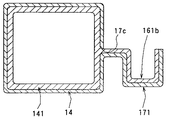
本実施形態では、梁部材14の素材としては、例えば、樹脂を用い、そして樹脂成形により梁部材14が一体成形されるようにする。そして、上述した第1実施形態で示した断熱保持部材161aが削除され、断熱保持部材161bだけで車両電気配線20を保持する。
【0063】
この場合、梁部材14および断熱保持部材161bを次のように別々に成形する。
【0064】
すなわち、梁部材分割体14の内側にシート状の樹脂発泡材を挿入して、筒状に形成する。このことにより、梁部材分割体14の内側においてダクト部141が樹脂発泡材により成形されることになる。また、断熱保持部材161bに相当するシート部材をシート状の樹脂発泡材により成形しておき、このシート部材の先端部に接着剤を付けた状態で開口部17c内を通してダクト部141に接着させる。その後、当該シート部材をケース断熱保持部材171の表面に沿わせるように配設する。
【0065】
以上により、断熱保持部材161bとしては、ダクト部141から開口部17c内を貫通して梁部材14の外側に延出して車両電気配線20を保持するように形成されることになる。
【0066】
(他の実施形態)
なお、上述した第1の実施形態では、ケース断熱保持部材171および梁部材分割体14bを一体成形されたものを用いるものを示したが、これに限らず、それぞれ別々に成形してから互いを接着材等で接続するようにしてもよい。
【0067】
さらに、上述した第1の実施形態では、ダクトケースとしては梁部材14を用いる例(すなわち、梁部材14に車両空調用ダクト構造を内包させるもの)を示したが、これに限らず、梁部材14に関わりないダクトケースを用いるようにしてもよい。
【0068】
なお、上述した第1の実施形態では、他の部材として車両電気配線(ワーヤーハーネス)を用いる例を示したが、これに限らず、ゴムホースなどの管材を用いるようにしてもよい。
【0069】
さらに、上述した第1の実施形態では、ダクト分割体14c、14dとしては、梁部材分割体14a、14bのそれぞれに対して空所300、310を開けるように上型、下型を組み合わせて空所300、310に流動状態の発泡材料を注入して固着されて成型されたものを用いるようにしたが、これに限らず、次のようにしてもよい
すなわち、梁部材分割体14a、14bのそれぞれに対して流動状態の発泡材料を吹き付けて固着されて成型されたものを用いるようにしてもよい。この場合でも、断熱保持部材161a、161bのそれぞれの部分を成形する際には、上型、下型に相当する治具を用いることが好ましい。
【0070】
さらに、上述した第1実施形態では、空調ダクト構造としては、計器盤部の内側に搭載されたものを示したが、これに限らず、空調ダクト構造としては、計器盤部に関係ない部分に搭載されるようにしてもよい。
【0071】
さらに、上述した第1及び第2の実施形態では、梁部材分割体14a、14bおよびケース断熱保持部材171としては、金属製のものを用いる例を示したが、これに限らず、樹脂製のものを用いるようにしてもよい。
【図面の簡単な説明】
【図1】本発明の車両用空調ダクト構造の第1実施形態を示す斜視図である。
【図2】図1に示す車両用空調ダクト構造が適用される計器盤を示す図である。
【図3】図1の梁部材を示す車幅方向の断面図である。
【図4】図1の梁部材を示す車両前後方向の断面図である。
【図5】図1の下側の梁部材分割体の図である。
【図6】図1の下側の梁部材分割体の部分断面図である。
【図7】図1の下側梁部材分割体の部分断面図である。
【図8】図1の上側の梁部材分割体の図である。
【図9】図1の上側の梁部材分割体の部分断面図である。
【図10】図1の下側のダクト分割体の断面図である。
【図11】図1の下側のダクト分割体の断面図である。
【図12】図1の上側の上側のダクト分割体の断面図である。
【図13】図1の下側のダクト分割体を成形する金型を示す断面図である。
【図14】図1の下側のダクト分割体を成形する金型を示す断面図である。
【図15】図1の下側のダクト分割体を成形する金型を示す断面図である。
【図16】図1の上側のダクト分割体を成形する金型を示す断面図である。
【図17】図1の上側のダクト分割体を成形する金型を示す断面図である。
【図18】本発明の車両用空調ダクト構造の第2実施形態を示す断面図である。
【符号の説明】
14…梁部材、20…車両電気配線、141…ダクト部材
14a、14b…梁部材分割体、150a、150b…半筒部、
14c、14d…ダクト分割体。[0001]
TECHNICAL FIELD OF THE INVENTION
The present invention relates to a vehicle air conditioning duct structure.
[0002]
[Prior art]
An indoor air-conditioning unit of a vehicle air-conditioning system is usually disposed at the center in the vehicle width direction inside an instrument panel in front of a vehicle interior (near a partition wall separating an engine room and a vehicle interior), and is temperature-controlled by the indoor air-conditioning unit. The conditioned air blows out from the center face outlet located at the center of the instrument panel in the vehicle width direction to the occupant face side at the center of the cabin, and is disposed at the left and right ends of the instrument panel in the vehicle width direction. The conditioned air is blown out from the side face outlet toward the occupant's face at the left and right ends of the vehicle.
[0003]
Therefore, an air-conditioning duct (side-face duct) for guiding the conditioned air from the indoor air-conditioning unit located at the center of the instrument panel in the vehicle width direction to the side-face outlets located at the left and right ends of the vehicle compartment is required.
Various wire harnesses (electric wires) are provided inside the instrument panel (for example, see Patent Document 1).
[0004]
[Patent Document 1]
JP-A-7-52683
[Problems to be solved by the invention]
By the way, for example, when the above-described wire harness is fixed so as to be along the air conditioning duct, an extra member such as a fixing member for fixing the wire harness to the air conditioning duct is required, which may increase the manufacturing cost. There is.
[0006]
In view of the above, an object of the present invention is to provide a vehicle air-conditioning duct structure capable of holding other components such as vehicle electrical wiring without increasing the number of components.
[0007]
[Means for Solving the Problems]
In order to achieve the above object, according to the first aspect of the present invention, there is provided a duct case (14) formed in a cylindrical shape, and a duct case (14) disposed inside the duct case and formed in a substantially cylindrical shape. The heat insulating members (14c, 14d) are formed so as to extend from the heat insulating members through the openings (171d, 171c) of the duct case to the outside of the duct case to hold the other members (20). A heat insulating holding member (161a, 161b).
[0008]
As described above, since the heat-insulating holding member is formed so as to extend from the heat-insulating member through the opening of the duct case and extend to the outside of the duct case, the heat-insulating holding member and the heat-insulating member are formed as one component. The other members can be held by the heat insulating holding member without increasing the number of parts.
[0009]
Here, if the case heat insulating holding member (171) is configured to extend from the duct case and hold the heat insulating holding member, as in the invention according to claim 2, the duct case can be used via the case heat insulating holding member. It will hold other members. For this reason, other members can be held more reliably.
[0010]
Here, the heat insulating member and the heat insulating holding member can be formed separately from each other and then connected to each other. However, as in the invention according to claim 3, the heat insulating member and the heat insulating holding member are integrally formed. It is preferable to use a molded product. In this case, the number of components can be reduced, and the manufacturing cost can be reduced, as compared with a case where the components are separately formed and then connected to each other.
[0011]
Specifically, as in the invention described in claim 4, it is preferable to use a foamed material as the heat insulating member and the heat insulating holding member in order to protect other members.
[0012]
Further, as in the invention according to claim 5, it is preferable to use a vehicle electric wiring as another member.
[0013]
Further, as in the invention as set forth in claim 6, the duct case is formed by combining at least two duct case divided bodies (14a, 14b) formed in a substantially semi-cylindrical shape with end portions (151a) of the two case divided bodies. , 151b) are preferably used.
[0014]
Specifically, as in the invention according to claim 7, the heat insulating member and the heat insulating holding member are formed by spraying and fixing a flowable heat insulating material to the duct case and the case heat insulating holding member. It may be used.
[0015]
According to the invention described in claim 8, the heat insulating member and the heat insulating holding member are formed in a cavity (300, 310) formed by combining a mold (301, 302, 304, 305) with the duct case and the case heat insulating holding member. ) May be formed by injecting and fixing a flowable heat insulating material.
[0016]
As in the ninth aspect of the invention, the duct case and the case heat-insulating holding member may be formed integrally.
[0017]
As in the tenth aspect, the duct case and the case heat insulation holding member may be made of metal.
[0018]
As in the eleventh aspect, a beam member of a vehicle may be used as the duct case.
[0019]
Incidentally, reference numerals in parentheses of the above-mentioned units are examples showing the correspondence with specific units described in the embodiments described later.
[0020]
BEST MODE FOR CARRYING OUT THE INVENTION
(1st Embodiment)
1 and 2 show a first embodiment of a vehicle air conditioning duct structure according to the present invention. The vehicle air-conditioning duct structure of FIG. 1 is mounted inside the instrument panel of FIG. The arrows in the drawings described below indicate the directions of the vehicle in the vehicle mounted state, that is, left and right, up and down, front and back.
[0021]
The
[0022]
An
[0023]
On the other hand, a beam member (reinforce bar) 14 extending in the vehicle width direction is provided above the
[0024]
The
[0025]
A
[0026]
Specifically, the
[0027]
The material of the duct divided
[0028]
As shown in FIG. 4, the vehicle
[0029]
On the other hand, as shown in FIG. 1, two
[0030]
As shown in FIG. 3, four
[0031]
Further, two center
[0032]
Here, as shown in FIG. 3, a ventilation
[0033]
The two center
[0034]
Although not shown in FIG. 1, a stay for supporting the steering device is attached to a portion of the
[0035]
Next, a holding structure of the vehicle
[0036]
FIG. 5 is a perspective view of the lower beam member divided
[0037]
As shown in FIG. 1, the three case heat-insulating
[0038]
Specifically, as shown in FIG. 5, the case heat insulating holding
[0039]
Here, an
[0040]
Further, as shown in FIG. 10, the heat-insulating
[0041]
FIG. 10 is a cross-sectional view showing a central portion of the heat-insulating
[0042]
Further, as shown in FIG. 12, the heat insulating holding
[0043]
Next, a method for forming the vehicle air conditioning duct structure according to the first embodiment will be specifically described.
[0044]
First, as a material for the upper and lower beam member divided
[0045]
Next, the outer shape of the sheet material is cut into a predetermined shape, the sheet member having the predetermined shape is pressed to form a substantially semi-cylindrical shape, and the
[0046]
Next, also as the lower beam member divided
[0047]
Next, the lower beam member divided
[0048]
Specifically, in the
[0049]
A flowing foam material is injected into the
[0050]
Next, the upper beam member divided
[0051]
Specifically, in the
[0052]
A flowing foam material is injected into the
[0053]
Next, the ventilation
[0054]
Next, the upper beam member divided
[0055]
As described above, the distal end portions of the duct divided
[0056]
Hereinafter, features of the present embodiment will be described. That is, a beam member 14 (duct case) formed in a cylindrical shape, duct divided
[0057]
Here, both the duct split 14c and the upper heat-insulating
[0058]
Further, a case heat insulating holding
[0059]
Further, as the duct divided
[0060]
By using a material made of a flexible foam material as the material of the heat
[0061]
(2nd Embodiment)
In the above-described first embodiment, an example in which the upper and lower beam member divided
[0062]
In the present embodiment, for example, a resin is used as a material of the
[0063]
In this case, the
[0064]
That is, a sheet-shaped resin foam material is inserted into the inside of the beam member divided
[0065]
As described above, the heat
[0066]
(Other embodiments)
In the above-described first embodiment, the case in which the case heat-insulating
[0067]
Further, in the above-described first embodiment, an example in which the
[0068]
In the above-described first embodiment, an example in which the vehicle electrical wiring (wire harness) is used as another member has been described. However, the present invention is not limited to this, and a tube material such as a rubber hose may be used.
[0069]
Furthermore, in the first embodiment described above, as the duct divided
[0070]
Furthermore, in the first embodiment described above, the air-conditioning duct structure is described as being mounted inside the instrument panel. However, the air-conditioning duct structure is not limited to this. It may be mounted.
[0071]
Further, in the above-described first and second embodiments, the example in which the metal member is used as the beam member divided
[Brief description of the drawings]
FIG. 1 is a perspective view showing a first embodiment of a vehicle air conditioning duct structure of the present invention.
2 is a diagram showing an instrument panel to which the vehicle air-conditioning duct structure shown in FIG. 1 is applied.
FIG. 3 is a sectional view in the vehicle width direction showing the beam member of FIG. 1;
FIG. 4 is a cross-sectional view of the beam member of FIG. 1 in a vehicle front-rear direction.
FIG. 5 is a view of a lower beam member divided body in FIG. 1;
FIG. 6 is a partial cross-sectional view of the lower beam member divided body of FIG. 1;
FIG. 7 is a partial sectional view of the lower beam member divided body of FIG. 1;
FIG. 8 is a view of the upper beam member divided body of FIG. 1;
FIG. 9 is a partial cross-sectional view of the upper beam member divided body of FIG. 1;
FIG. 10 is a sectional view of the lower duct segment of FIG. 1;
FIG. 11 is a sectional view of the lower duct segment of FIG. 1;
FIG. 12 is a cross-sectional view of the upper divided duct of FIG. 1;
FIG. 13 is a cross-sectional view showing a mold for molding the lower duct segment of FIG. 1;
FIG. 14 is a cross-sectional view showing a mold for molding the lower duct segment of FIG. 1;
FIG. 15 is a cross-sectional view showing a mold for molding the lower duct segment of FIG. 1;
FIG. 16 is a cross-sectional view showing a mold for molding the upper divided duct of FIG. 1;
FIG. 17 is a cross-sectional view showing a mold for molding the upper divided duct of FIG. 1;
FIG. 18 is a sectional view showing a second embodiment of the vehicle air conditioning duct structure of the present invention.
[Explanation of symbols]
14 beam member, 20 vehicle electric wiring, 141
14c, 14d: divided ducts.
Claims (11)
前記ダクトケースの内側に配設されて略筒状に形成されている断熱部材(14c、14d)と、
前記断熱部材から前記ダクトケースの開口部(171d、171c)内を貫通して前記ダクトケースの外側に延出して他の部材(20)を保持するように形成される断熱保持部材(161a、161b)と、
を備えることを特徴とする車両用空調ダクト構造。A duct case (14) formed in a cylindrical shape,
A heat insulating member (14c, 14d) disposed inside the duct case and formed in a substantially cylindrical shape;
A heat insulating holding member (161a, 161b) formed to extend from the heat insulating member through the inside of the opening (171d, 171c) of the duct case to the outside of the duct case to hold another member (20). )When,
An air conditioning duct structure for a vehicle, comprising:
Priority Applications (1)
| Application Number | Priority Date | Filing Date | Title |
|---|---|---|---|
| JP2002356564A JP2004189016A (en) | 2002-12-09 | 2002-12-09 | Air-conditioning duct structure for vehicle |
Applications Claiming Priority (1)
| Application Number | Priority Date | Filing Date | Title |
|---|---|---|---|
| JP2002356564A JP2004189016A (en) | 2002-12-09 | 2002-12-09 | Air-conditioning duct structure for vehicle |
Publications (1)
| Publication Number | Publication Date |
|---|---|
| JP2004189016A true JP2004189016A (en) | 2004-07-08 |
Family
ID=32756868
Family Applications (1)
| Application Number | Title | Priority Date | Filing Date |
|---|---|---|---|
| JP2002356564A Pending JP2004189016A (en) | 2002-12-09 | 2002-12-09 | Air-conditioning duct structure for vehicle |
Country Status (1)
| Country | Link |
|---|---|
| JP (1) | JP2004189016A (en) |
Cited By (2)
| Publication number | Priority date | Publication date | Assignee | Title |
|---|---|---|---|---|
| JP2009241889A (en) * | 2008-03-31 | 2009-10-22 | Furukawa Electric Co Ltd:The | Air duct for air conditioner |
| JP2010149731A (en) * | 2008-12-25 | 2010-07-08 | Kubota Corp | Air conditioning structure of working vehicle |
-
2002
- 2002-12-09 JP JP2002356564A patent/JP2004189016A/en active Pending
Cited By (2)
| Publication number | Priority date | Publication date | Assignee | Title |
|---|---|---|---|---|
| JP2009241889A (en) * | 2008-03-31 | 2009-10-22 | Furukawa Electric Co Ltd:The | Air duct for air conditioner |
| JP2010149731A (en) * | 2008-12-25 | 2010-07-08 | Kubota Corp | Air conditioning structure of working vehicle |
Similar Documents
| Publication | Publication Date | Title |
|---|---|---|
| JPH11165524A (en) | Air conditioning duct device for automobile | |
| JP3930099B2 (en) | Instrument panel for automobile | |
| JP3542288B2 (en) | Instrument panel support structure for automobiles | |
| JPH11165563A (en) | Front interior component assembly for automobile | |
| JP2001213139A (en) | Air guide duct for vehicle | |
| JP2004001687A (en) | Intensity member for vehicle | |
| JP4151181B2 (en) | Electrical wiring structure in the instrument panel for vehicles | |
| US9205721B2 (en) | Cross-car structural support with integrated HVAC floor duct | |
| JPH11165655A (en) | Reinforcing member structure of car body | |
| JPH1067260A (en) | Instrument panel for automobile | |
| JP2004189016A (en) | Air-conditioning duct structure for vehicle | |
| JP2002087045A (en) | Air-conditioning duct | |
| JP4042011B2 (en) | Instrument panel air guide duct | |
| JP2004161136A (en) | Air-conditioning duct structure for vehicle, girder member structure for vehicle | |
| JP2006206030A (en) | Vehicle ceiling member | |
| JP2003136942A (en) | Car mounting method and structure for air-conditioner device | |
| JP4218332B2 (en) | Vehicle air conditioning duct structure | |
| JP4135490B2 (en) | Vehicle air conditioning duct structure | |
| JP4378609B2 (en) | Air duct | |
| JP3862484B2 (en) | Instrument panel device for automobile | |
| JP4364587B2 (en) | Interior materials for vehicles | |
| JP6745692B2 (en) | Interior material | |
| JPH11227453A (en) | Reinforcing bar for passenger car | |
| JP2001138772A (en) | Instrument panel | |
| JP2002187422A (en) | Mounting structure of air conditioning duct for vehicle |
Legal Events
| Date | Code | Title | Description |
|---|---|---|---|
| A621 | Written request for application examination |
Free format text: JAPANESE INTERMEDIATE CODE: A621 Effective date: 20050331 |
|
| A131 | Notification of reasons for refusal |
Free format text: JAPANESE INTERMEDIATE CODE: A131 Effective date: 20071023 |
|
| A02 | Decision of refusal |
Free format text: JAPANESE INTERMEDIATE CODE: A02 Effective date: 20080304 |