JP2004188825A - Injection mold - Google Patents
Injection mold Download PDFInfo
- Publication number
- JP2004188825A JP2004188825A JP2002360383A JP2002360383A JP2004188825A JP 2004188825 A JP2004188825 A JP 2004188825A JP 2002360383 A JP2002360383 A JP 2002360383A JP 2002360383 A JP2002360383 A JP 2002360383A JP 2004188825 A JP2004188825 A JP 2004188825A
- Authority
- JP
- Japan
- Prior art keywords
- sprue
- injection
- shunt
- mold
- runner
- Prior art date
- Legal status (The legal status is an assumption and is not a legal conclusion. Google has not performed a legal analysis and makes no representation as to the accuracy of the status listed.)
- Granted
Links
Images


Abstract
Description
【0001】
【発明の属する技術分野】
この発明は、熱硬化性または熱可塑性の合成樹脂材料、ゴム、ゴム状弾性材料(エラストマー)等を成型材料とする射出成型に適した射出成型用金型に関する。
【0002】
【従来の技術】
射出成型時には射出充填圧力に比例して成型材料が射出せん断発熱により自己発熱し、キャビティに注入される材料温度が上昇する現象が生じる。この射出充填圧力に関係した射出発熱での材料の昇温は、ゴムや熱硬化性樹脂のように熱により硬化反応が促進される材料の成型にとっては、金型内での材料の硬化反応時間やゴムの場合の加硫時間が短縮されるので生産性の面で好都合である。他方、熱可塑性樹脂材料では、射出充填圧力が大きい場合には、スプルーやランナー、ゲート等の金型通路の途中で冷却され固化しないよう、キャビティへの材料充填不足とならないように高速充填されるので好ましい。しかし、射出充填圧力による昇温は、高温になりすぎると熱可塑性樹脂自体の分解劣化の原因となるので好ましくない。
【0003】
すなわち、ゴムや熱硬化性樹脂材料の射出成型においては、材料がスコーチ(材料焼け)しない範囲で可能な限り高い射出充填圧力を設定したい。他方、熱可塑性樹脂材料の射出成型においては、射出充填不足にならない範囲で可能な限り低い射出充填圧力に設定したい。
【0004】
このため、射出成型工程では、射出成型条件を設定する際に、使用材料と金型との組み合わせに応じた好適な射出速度と射出充填圧力を確保できるよう、最適なノズル径を選択することが要求され、成型する製品(成型品)毎に最適なノズル径を備えたノズルに交換する作業を必要としている。
【0005】
このノズルの交換作業は、成型用金型を射出成型機に取り付けた状態では行えない構造のものがあり、金型を射出成型機から取り外し、金型を分解して行なわなければならない場合がある。すなわち、金型の取り外し作業や型ばらし作業を行ってノズルを交換し、再び金型の組み立て作業や取付作業を行い、成型温度の調整等の各作業を順次行っていた。しかし、これらの作業は煩雑であり相当の時間を要することになり、また多種類のノズルを準備しておかなければならず、コストが大きくなっていた。このため、複数のキャビティに対してその都度ノズル交換の手間を省くために、特許文献1に記載された射出成型用金型がある。この射出成型用金型は、複数のキャビティに対して、それぞれ、ピンポイントゲートを用いた3プレート構造の射出成型用金型において、スプル部から各キャビティのゲートに向けて樹脂流路が分岐されているランナに向けて、上記ランナのストリッパプレート側には、2次スプルロックピンが、その先端を各ゲートに対応する2次スプル部に臨ませて、金型を成型機に取り付けた状態で外部から位置調整できるように配置された構造を備えたものである。
【0006】
【特許文献1】
特開平11−19975号
【0007】
【発明が解決しようとする課題】
しかしながら、特許文献1に記載された成型用金型の場合、2次スプル毎に2次スプルロックピンを調整する必要がある。この調整作業は手作業で行われるものであり、しかも複数個の2次スプルロックピンを調整することから、作業性が十分に向上したとは言い難い。すなわち、複数個の2次スプルロックピンを調整する際に、その調整にバラツキが生じ2次スプル毎に流動抵抗が異なってしまうおそれがあり、同時に加工された成型品の間で品質のバラツキが生じるおそれがある。したがって、流動抵抗を等しくするよう2次スプルロックピンを調整しなければならないが、この調整作業は煩雑であり、場合によって熟練を必要とする。
【0008】
しかも、射出成型の場合には、同一の成型品であっても、使用材料の製造ロット毎に材料の流動性にバラツキがあり、同一の射出条件を設定して射出成型した場合でも、射出充填圧力が変動して、所望の成型品を得られない場合が生じる。さらに、ゴムや熱硬化性樹脂の場合には、材料の製造ロット毎に熱硬化反応速度や加硫速度にもバラツキが生じ、同一の射出条件が設定されていても、熱硬化反応速度が大きすぎる材料ロットでは、射出充填時にスコーチを生じてしまい、熱硬化反応速度が小さすぎる材料ロットでは、成型品の熱硬化反応不足を生じて、所望の品質の成型品を得ることができないおそれがある。したがって、成型品の品質を確保するために、使用材料や金型の変更時と同様に、材料の製造ロット毎にも、熱硬化反応速度に応じてノズル径を変更して対応している。すなわち、ノズル径の変更によって射出充填圧力が変更され、その結果、射出発熱量が変更されることになる。
【0009】
また、射出成型機の運転時間が長くなると、材料の流路が摩耗したり、流路内に材料が滞留してしまうおそれがある。このような場合にも、流路抵抗が変動するから、射出充填圧力が変動するおそれがある。すなわち、経時的にも射出充填圧力が変動するおそれがあり、運転中であっても常時射出充填圧力の変動を監視して、この変動に応じた調整を行えるようにすることが好ましい。
【0010】
そこで、この発明は、射出充填圧力の設定を任意に行えるようにすることができるようにし、成型品が変更された場合であっても、同一成型品の成型加工時に製造ロットの異なる材料が使用される場合であっても、容易に射出充填圧力の設定を変更でき、品質にバラツキのない成型品を加工することができる射出成型用金型を提供することを目的としている。
【0011】
【課題を解決するための手段】
前記の目的を達成するための技術的手段として、この発明に係る射出成型用金型は、固定型のランナーとノズルタッチの両面間に形成されているスプルーに同心的に分流子を遊挿し、前記分流子を前記スプルーの軸方向に移動可能に支持し、前記分流子を移動させる駆動手段を有することを特徴としている。
【0012】
前記分流子を移動させることにより、スプルーに対する位置関係が変更させる。スプルーに遊挿された分流子のため材料の流路は断面環状となっており、分流子の位置によってこの流路の長さが変更され、流路の抵抗が異なることになる。また、スプルーは円錐形の内面で形成され、分流子の遊挿位置によって、流路の面積が異なることになり、流路抵抗が変更されることになる。すなわち、分流子の位置を異ならせることによりノズルの径を異ならせた場合と同様の機能を果たすことができる。この流路抵抗の変化によって射出充填圧力が変更され、成型品に適した射出充填圧力を得ることができる。しかも、分流子の移動は、前記駆動手段によって行うので、この駆動手段の駆動量、例えばモータを用いた場合にはその回転角度を検出することにより、分流子の移動量を知ることができるから、成型品や材料に応じた分流子の位置を予め求めておくことにより、当該成型品等に最適な流路抵抗を設定することができる。
【0013】
また、請求項2の発明に係る射出成型用金型は、ランナー割面とキャビティ割面とを別個に有する3プレート金型構造を有する射出成型用金型において、ランナーとキャビティの両面間に形成されているゲートと同軸に、ランナーストリッパプレートに該ランナーストリッパプレートを貫通する貫通孔を形成し、前記貫通孔に分流子を、該貫通孔の軸方向に移動可能に支持してあることを特徴としている。
【0014】
3プレート構造による場合にはランナーストリッパプレートに、キャビティに通じたゲートの開口に臨ませて貫通孔を形成することができる。したがって、この貫通孔に前記分流子を移動可能に設けることによりゲートの開口面積を変更させて、該ゲートの開口部における流路抵抗を変更させることができる。これにより、キャビティへの射出充填圧力を変更することができる。すなわち、分流子のゲートの開口に対する位置を調整することにより、射出充填圧力を調整することができる。しかも、各ゲート毎に調整できる。
【0015】
また、請求項3の発明に係る射出成型用金型は、ランナー割面とキャビティ割面とを別個に有する3プレート金型構造を有する射出成型用金型において、ランナーストリッパプレートのランナーとノズルタッチの両面間に形成されているスプルーに同心的にスプルー用分流子を遊挿し、前記スプルー用分流子を前記スプルーの軸方向に移動可能に支持し、前記スプルー用分流子を移動させる駆動手段を有し、ランナーとキャビティの両面間に形成されているゲートと同軸に、ランナーストリッパプレートに該ランナーストリッパプレートを貫通する貫通孔を形成し、前記貫通孔にゲート用分流子を、該貫通孔の軸方向に移動可能に支持してあることを特徴としている。
【0016】
すなわち、スプルーとゲートに臨む位置との双方に分流子を設けた構造である。スプルーとゲートの開口の部分とで流路抵抗の増減を調整できるから、射出充填圧力をより最適となるよう調整することができる。
【0017】
また、請求項4の発明に係る射出成型用金型は、射出成型時の射出充填圧力を測定する圧力検出手段と、前記駆動手段に駆動信号を送出する駆動制御手段とを備え、前記駆動制御手段は、成型品に応じた射出充填圧力についての設定データを有すると共に、外部からの操作によって比較データを入力でき、前記設定データまたは比較データと前記検出データとを比較して、所望の射出充填圧力に応じた位置まで前記分流子を移動させる駆動信号を送出し、前記駆動手段は、前記駆動信号に従って作動して、前記分流子の移動位置を変更させることを特徴としている。
【0018】
前記圧力検出手段により射出充填圧力が検出されると、その検出データが前記駆動制御手段へ送出される。駆動制御手段では、例えば成型品に応じた最適な射出充填圧力に関するデータを設定データとして設定しておき、この設定データと検出データとを比較して、等しい射出充填圧力となる位置に前記分流子を移動させるよう、駆動信号を送出する。この駆動信号を受けて前記駆動手段が駆動して分流子を移動させる。また、スコーチの発生等成型品の品質を確認して、外部からの操作により比較データを変更して駆動信号を変更することにより、材料ロットの変更に応じた射出充填圧力に調整する。
【0019】
【発明の実施の形態】
以下、図示した好ましい実施の形態に基づいて、この発明に係る射出成型用金型を具体的に説明する。なお、この実施形態では、ゴムを材料として射出成型するのに適した射出成型用金型を示している。
【0020】
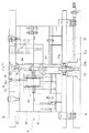
図1はこの発明に係る射出成型用金型及び射出成型機の一部の概略構造を説明する断面図であり、ケーシング1に水平方向の押出装置2と垂直方向の射出シリンダ3とを備えており、射出シリンダ3の下方に金型4が配されて、射出シリンダ3から射出される成型材料がこの金型4内に供給されるようにしてある。
【0021】
前記押出装置2は、筒状のシリンダ部21と、その内部に回動可能に収容されたスクリュー22とで構成されている。シリンダ部21の一部には供給口23が設けられており、成型材料であるゴムがこの供給口23からシリンダ部21内に供給される。シリンダ部21の先端部には縮径されて首部24が設けられており、この首部24の前方には、拡径部25a に弁体25b が収容された逆止弁25が設けられている。この逆止弁25の下流側に連通路26が設けられ、逆止弁25は該連通路26を介して前記射出シリンダ3のシリンダ部31と連通している。なお、この逆止弁25は押出装置2から射出シリンダ3に材料が流れることを許容し、逆方向の流れを阻止する。
【0022】
前記連通路26は、シリンダ部31の下部に配された射出ポット部32に連通している。この射出シリンダ3は筒状のシリンダ部31内に摺動可能にプランジャ33が収容された構造とされており、下端部に前記射出ポット部32が設けられている。この射出ポット部32の内面は円錐形の内面で形成され、下端部には供給路34が連通している。前記プランジャ33の先端形状は、射出ポット部32の円錐形と合致する円錐形に形成されており、プランジャ33は、下端まで摺動した場合には、その先端部が前記供給路34の上部に位置するようにしてある。また、前記供給路34の下端部には着脱可能にノズル5が設けられている。
【0023】
前記金型4は可動型である下型41と固定型である上型42、この上型42の上部に取り付けられるランナーストリッパプレート43とにより構成されている。ランナーストリッパプレート43の上方には、成型機と上型42とを固定し、前記ノズル5と上型42の後述するノズルタッチ11a との位置決めを行うアッパクランピングプレート8が配されている。このアッパクランピングプレート8に、ヒーター6aが内蔵された上熱盤6が被せられ、該上熱盤6の上方には断熱盤7aを介して上ダイプレート71が配されている。前記下型41にはヒーター41a が内蔵されている。この下型41の下方に断熱盤7bを介して下ダイプレート72が配されている。そして、前記上ダイプレート71と下ダイプレート72とはタイバー73によって連繋され、下型41の型締め、型開きの際の移動を案内する。
【0024】
前記ランナーストリッパプレート43には、スプルー11とランナー12とが形成されている。スプルー11はランナーストリッパプレート43のほぼ中央部で、上面であるノズルタッチ面から下面であるランナー割面に貫通した透孔で形成され、上端部のノズルタッチ11a (図2及び図3参照)で前記ノズル5に接続するようにしてある。このスプルー11の内面は、円錐台形の内面で形成されている。また、スプルー11の下端部には前記ランナー12の基端部が連通している。ランナー12は、ランナーストリッパプレート43の下面に溝状に形成されており、複数のランナー12がスプルー11の下端部からほぼ放射状に伸張させてある。このランナー12のそれぞれの先端部にゲート13が連通している。なお、ランナーストリッパプレート43の下面は前記上型42の上面に密着して、ランナー12は溝状の底部が上型42に閉鎖されて通路状に形成されている。
【0025】
前記ゲート13は上型42の上面から、該上型42の下面に形成された上側キャビティ14a に連通する透孔で形成されている。前記下型41には、上側キャビティ14a と協働してキャビティ14を形成することになる下側キャビティ14b が形成されている。したがって、このキャビティ14は、ゲート13とランナー12、スプルー11、供給路34を介して射出シリンダ3の射出ポット部32と連通している。
【0026】
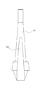
前記下型41と上型42、ランナーストリッパプレート43とを密着させた状態で、前記スプルー11と連通するガイド孔15が、下型41と上型42、断熱盤7aとを貫通して形成されている。そして、このガイド孔15に棒状の分流子16が、該ガイド孔15に案内されて摺動可能に遊挿されている。この分流子16の先端部はスプルー11内に位置しており、先端の形状はスプルー11の円錐台形と合致する円錐形の外面で形成されている。したがって、スプルー11においては、流路形状が環状に形成されている。
【0027】
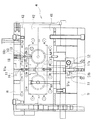
前記分流子16を移動させる駆動手段50がロアクランピングプレート9内に設けられている。なお、該駆動手段50は前記下ダイプレート72に設けることもできる。この駆動手段50は、図2及び図3に示すように、ウォームホイール51とウォーム52とを組み合わせたウォームギヤにより構成されている。ウォーム52は、図2に示すように、前記ロアクランクピングプレート9の上方に、水平方向に掛け渡されて回動自在に支持された駆動ロッド53の中央部に形成されており、この駆動ロッド53に図示しないモータ等の駆動源から回動力が伝達される。ウォームホイール51のボス部51a の内面には雌ネジが51b が形成されている。前記分流子16は、下端部に支持ロッド17が接続されており、この支持ロッド17が前記ガイド孔15に遊挿されている。この支持ロッド17の下部でガイド孔15から突出した部分には、前記雌ネジ51b と螺合する雄ネジ部17a が形成されている。また、この支持ロッド17は回動が阻止されている。
【0028】
以上により構成されたこの発明に係る射出成型機の作用を、以下に説明する。
【0029】
前記図示しない駆動源が作動すると前記駆動ロッド53が回動して、ウォーム52が回動する。このウォーム52に螺合しているウォームホイール51も回動する。該ウォームホイール51のボス部51a には雌ネジ51b が形成されており、回動が阻止されている前記支持ロッド17の雄ネジ部17a が該雌ネジ51b に螺合しているから、該支持ロッド17がウォームホイール51の回動方向に応じてガイド孔15内を昇降することになる。支持ロッド17の上端部には前記分流子16が接続してあるから、該分流子16がスプルー11内を昇降して移動する。
【0030】
スプルー11は前記分流子16が内部に位置していることにより、断面環状の流路が形成された状態となっている。この分流子16のスプルー11に対する位置に応じてこの流路の長さと面積が変更されるから、流路抵抗が変更されることになる。
【0031】
一方、成型材料であるゴムは前記供給口23から供給され、前記スクリュー22の回転によってシリンダ部21を首部24へ向けて押し送られ、逆止弁25を通過し、連通路26を通って射出ポット部32へ供給される。射出ポット部32に成型材料が供給されると、前記プランジャ33が押し上げられることになり、射出量に対応した位置まで押し上げられると前記スクリュー22の回転が停止して成型材料の射出ポット部32への供給が停止する。次いで、図示しない駆動源によってプランジャ33が押下される。このとき、射出ポット部32内の成型材料は前記連通路26を通って押出装置2に戻ろうとするが、前記逆止弁25に阻止されているため、逆流することはない。したがって、プランジャ33の下降によって射出ポット部32内の成型材料は、供給路34を通ってノズル5からスプルー11へ射出されることになる。スプルー11に供給された成型材料は、該スプルー11内に位置している分流子16の周囲の流路を通ってランナー12に押し送られ、さらにゲート13を通ってキャビティ14内に射出されることになる。次いで、加熱硬化され、型開きされてキャビティ14内で固化した成型品が取り出される。
【0032】
成型材料の変更があった場合や、成型品を変更する場合等で、射出充填圧力を変更する必要が生じた場合には、前記駆動ロッド53を回動させて、前述したように分流子16を上昇または下降させて所定の位置に位置付かせる。これにより、スプルー11における流路長が変更されて、流路抵抗が変更されるから、射出充填圧力が変更される。また、スプルー11は成型材料の流動性が良好となるようにノズル5側が縮径された円錐形の内面で形成されている。このため、分流子16もスプルー11の円錐形と合致する円錐形の外面で形成されている。このため、分流子16の位置が変更されると、スプルー11の流路面積も変更されて、流路抵抗が変更されるから、射出充填圧力が変更される。また、必要とされる射出充填圧力を得られる分流子16の位置が予め認識されていれば、当該位置に分流子16を位置させることによって簡便に所定の射出充填圧力に設定することができる。なお、分流子16の位置は、例えば支持ロッド17の位置を検出する位置センサ等を設けることによって容易に確認することができる。また、駆動手段の初期位置を定めて、該初期位置からの回転角度に応じて分流子16の位置を定めることもできる。
【0033】
さらに、図2と図3、図5に示すように、ゲート13の開口に対しても、分流子18が設けられている。すなわち、前記ランナーストリッパプレート43を貫通したガイド孔19を形成し、このガイド孔19に分流子18が移動可能に案内されて設けられている。この分流子18の先端をランナー11と連通するゲート13の開口に臨ませてあり、該分流子18の移動によって該開口との関係において開口面積を調整することができるようにしてある。また、この分流子18の移動は、前記分流子16のように、駆動源の動力を伝達させて行うこともでき、また、例えば分流子18の支持ロッド18a に雄ネジを形成し、前記ガイド孔19に該雄ネジと螺合する雌ネジを形成して、該支持ロッド18a を回動させてこれら雄ネジと雌ネジの螺合関係によって分流子18を移動させるようにしても構わない。
【0034】
前記分流子18を下降させて、先端をゲート13の開口に接近させると、該開口の面積が小さくなって流路抵抗を増加させることができる。また、分流子18を上昇させると前記開口面積が大きくなるので流路抵抗を減少させることができる。したがって、分流子18の位置を調整することにより射出充填圧力を調整することができる。
【0035】
さらに、分流子16のように駆動源の動力を利用して移動させるようにした場合には、射出充填圧力を測定することにより、その検出データに基づいて分流子16の位置を変更させることができる。例えば、前記プランジャ33を押下させる際の負荷となる圧力を測定する圧力検出手段61を設け、この圧力検出手段61により測定された射出充填圧力に関する検出データを、駆動制御手段62に送出する。駆動制御手段62には成型材料や成型品に応じた最適な射出充填圧力が設定データとして予め登録されており、この設定データと前記検出データとを比較し、その差に応じて射出充填圧力の増減に関する駆動信号を駆動手段63に対して出力する。駆動手段63ではこの駆動信号に基づいて要求された角度と方向で前記駆動ロッド53を回動させる。これにより、分流子16が移動して射出充填圧力が変更される。また、前記駆動制御手段62には外部からの操作によって比較データを設定することができるようにしてある。例えば、同一の成型品を同一の材料で成型する場合に、材料ロットが変更されたことにより加硫速度等が変化してしまう場合がある。このような場合には、成型品を確認して例えばスコーチが発生している場合には、分流子16を移動させてスプルー11における流路抵抗を増減させる必要があるから、比較データを入力して射出充填圧力を変更させる。
【0036】
【発明の効果】
以上説明したように、この発明に係る射出成型用金型によれば、スプルーに遊挿した分流子を移動させることにより、スプルーにおける流路抵抗を変更することができ、これにより射出充填圧力を調整することができる。したがって、材料や金型が変更された場合、ノズルを交換することなく最適な射出充填圧力に設定でき、良好な成型品を得ることができる。しかも、駆動手段の動力によって分流子を移動させるので、人手による作業の場合のような煩雑さがなく、射出充填圧力の調整作業を簡便に行うことができる。このため、射出成型機による生産性を向上させることができる。
【0037】
また、請求項2の発明に係る射出成型用金型によれば、ゲートの開口に臨ませた分流子を移動させることにより、ゲートの開口面積を調整できる。このため、ゲートの開口における流路抵抗を増減することができ、射出充填圧力を調整することができしたがって、材料や金型が変更された場合、ノズルを交換することなく最適な射出充填圧力に設定でき、良好な成型品を得ることができる。
【0038】
また、請求項3の発明に係る射出成型用金型によれば、スプルーにおける流路抵抗とゲートにおける流路抵抗の双方を簡便に調整することができるので、射出充填圧力を容易に最適な大きさに調整することができる。
【0039】
また、請求項4の発明に係る射出成型用金型によれば、リアルタイムで射出充填圧力を調整することができる。このため、成型品や金型の交換時にも、材料ロットの変更による成型品の品質変化にも、さらに流路の摩耗や流路内に材料が滞留した場合等の経時的な射出充填圧力の変動にも、容易に、かつ、迅速に対応することができ、ゴムや熱硬化性樹脂を材料とする場合のスコーチや熱硬化反応不足を生じさせずに、また、熱可塑性樹脂を材料とする場合の材料の熱分解や冷却固化状態の安定化に寄与して、いずれの場合であっても、成型品の品質を安定して良好に保つことができる。
【図面の簡単な説明】
【図1】この発明に係る射出成型用金型及び射出成型機の一部の概略構造を説明する断面図である。
【図2】この発明に係る射出成型用金型の概略構造を説明する一部切断正面図である。
【図3】図2に示す金型の一部切断側面図である。
【図4】この発明に係る要部の構造を示す断面図である。
【図5】この発明に係る要部の構造を示す断面図である。
【図6】この発明に係る射出成型用金型及び射出成型機の動作を制御する制御手段を説明するブロック図である。
【符号の説明】
1 ケーシング
2 押出装置
3 射出シリンダ
31 シリンダ部
32 射出ポット部
34 供給路
4 金型
41 下型
42 上型
43 スプルーストリッパプレート
5 ノズル
8 アッパクランピングプレート
9 ロアクランクピンクグプレート
11 スプルー
11a ノズルタッチ
12 ランナー
13 ゲート
14 キャビティ
15 ガイド孔
16 分流子(スプルー用)
17 支持ロッド
17a 雄ネジ部
18 分流子(ゲート用)
19 ガイド孔
50 駆動手段
51 ウォームホイール
52 ウォーム
53 駆動ロッド
61 圧力検出手段
62 駆動制御手段
63 駆動手段
71 上ダイプレート
72 下ダイプレート
73 タイバー[0001]
TECHNICAL FIELD OF THE INVENTION
The present invention relates to an injection molding die suitable for injection molding using a thermosetting or thermoplastic synthetic resin material, rubber, a rubber-like elastic material (elastomer), or the like as a molding material.
[0002]
[Prior art]
At the time of injection molding, the molding material self-heats due to injection shear heat in proportion to the injection filling pressure, and a phenomenon occurs in which the temperature of the material injected into the cavity rises. The temperature rise of the material due to the injection heat generated in relation to the injection filling pressure is required for molding of a material in which a curing reaction is accelerated by heat, such as rubber or thermosetting resin. In the case of rubber or rubber, the vulcanization time is shortened, which is advantageous in terms of productivity. On the other hand, when the injection filling pressure is large, the thermoplastic resin material is filled at a high speed so as not to be cooled and solidified in the middle of a mold passage such as a sprue, a runner, a gate, etc. so that the material is not insufficiently filled in the cavity. It is preferred. However, it is not preferable to raise the temperature by the injection filling pressure, because if the temperature is too high, it will cause degradation of the thermoplastic resin itself.
[0003]
That is, in the injection molding of rubber or a thermosetting resin material, it is desired to set the injection filling pressure as high as possible within a range where the material does not scorch (burn the material). On the other hand, in injection molding of a thermoplastic resin material, it is desirable to set the injection filling pressure as low as possible within a range that does not cause insufficient injection filling.
[0004]
For this reason, in the injection molding process, when setting the injection molding conditions, it is necessary to select an optimal nozzle diameter so as to secure a suitable injection speed and injection filling pressure according to the combination of the used material and the mold. It is required, and it is necessary to replace the nozzle with an optimal nozzle diameter for each product to be molded (molded product).
[0005]
This nozzle replacement work may not be possible with the molding die attached to the injection molding machine, and it may be necessary to remove the mold from the injection molding machine and disassemble the mold. . That is, the nozzles are exchanged by performing the mold removing operation and the mold separating operation, the mold assembling operation and the mounting operation are performed again, and the respective operations such as adjusting the molding temperature are sequentially performed. However, these operations are complicated and require a considerable amount of time, and various types of nozzles must be prepared, thus increasing the cost. For this reason, there is an injection molding die described in Patent Literature 1 in order to save the trouble of exchanging the nozzle for each of a plurality of cavities. In this injection mold, a resin flow path is branched from a sprue portion to a gate of each cavity in an injection mold having a three-plate structure using a pinpoint gate for each of a plurality of cavities. A secondary sprue lock pin is provided on the stripper plate side of the runner, with its tip facing the secondary sprue part corresponding to each gate, and the mold is attached to the molding machine. It has a structure arranged so that the position can be adjusted from the outside.
[0006]
[Patent Document 1]
JP-A-11-19975
[Problems to be solved by the invention]
However, in the case of the molding die described in Patent Literature 1, it is necessary to adjust the secondary sprue lock pin for each secondary sprue. This adjustment is performed manually, and since the plurality of secondary sprue lock pins are adjusted, it is difficult to say that the workability has been sufficiently improved. That is, when adjusting a plurality of secondary sprue lock pins, the adjustment may vary, and the flow resistance may be different for each secondary sprue. May occur. Therefore, the secondary sprue lock pin must be adjusted to make the flow resistance equal, but this adjustment operation is complicated and requires skill in some cases.
[0008]
In addition, in the case of injection molding, even if the same molded product is used, the fluidity of the material varies depending on the production lot of the material used. The pressure fluctuates and a desired molded product may not be obtained. Furthermore, in the case of rubber and thermosetting resin, the thermosetting reaction rate and the vulcanization rate also vary for each production lot of the material, and the thermosetting reaction rate is large even if the same injection conditions are set. If the material lot is too large, scorch is generated at the time of injection filling, and if the thermosetting reaction rate is too low, the thermosetting reaction of the molded product may be insufficient, and a molded product of desired quality may not be obtained. . Therefore, in order to ensure the quality of the molded product, the nozzle diameter is changed according to the thermosetting reaction speed for each production lot of the material, as in the case of changing the material used and the mold. That is, the injection filling pressure is changed by changing the nozzle diameter, and as a result, the injection heat generation amount is changed.
[0009]
Further, when the operation time of the injection molding machine is prolonged, there is a possibility that the flow path of the material is worn or the material stays in the flow path. Also in such a case, since the flow path resistance fluctuates, the injection filling pressure may fluctuate. That is, there is a possibility that the injection filling pressure may fluctuate over time, and it is preferable that the fluctuation of the injection filling pressure is constantly monitored even during operation, and adjustments can be made in accordance with the fluctuation.
[0010]
Therefore, the present invention enables the injection filling pressure to be set arbitrarily, and even if the molded product is changed, different materials from different production lots are used when molding the same molded product. It is an object of the present invention to provide an injection mold capable of easily changing the setting of the injection filling pressure and processing a molded product having no variation in quality.
[0011]
[Means for Solving the Problems]
As a technical means for achieving the above object, the injection molding die according to the present invention, the shunt is loosely inserted concentrically into the sprue formed between both sides of the fixed runner and the nozzle touch, The shunt is supported so as to be movable in the axial direction of the sprue, and a driving unit for moving the shunt is provided.
[0012]
By moving the shunt, the positional relationship with respect to the sprue is changed. The flow path of the material for the shunt inserted loosely into the sprue has an annular cross section, and the length of the flow path changes depending on the position of the shunt, and the resistance of the flow path differs. In addition, the sprue is formed by a conical inner surface, and the area of the flow path varies depending on the play insertion position of the shunt, thereby changing the flow path resistance. In other words, by changing the position of the shunt, the same function as in the case where the diameter of the nozzle is changed can be achieved. The injection filling pressure is changed by the change in the flow path resistance, and an injection filling pressure suitable for a molded product can be obtained. In addition, since the movement of the shunt is performed by the driving means, the amount of movement of the shunt can be known by detecting the driving amount of the driving means, for example, the rotation angle when a motor is used. By previously finding the position of the shunt in accordance with the molded product or the material, it is possible to set an optimal flow path resistance for the molded product or the like.
[0013]
According to a second aspect of the present invention, there is provided an injection mold having a three-plate mold structure having a runner split surface and a cavity split surface separately. The runner stripper plate is formed with a through hole passing through the runner stripper plate coaxially with the gate, and the shunt is supported in the through hole so as to be movable in the axial direction of the through hole. And
[0014]
In the case of the three-plate structure, a through-hole can be formed in the runner stripper plate so as to face the opening of the gate communicating with the cavity. Therefore, by providing the shunt movably in the through hole, the opening area of the gate can be changed, and the flow path resistance at the opening of the gate can be changed. Thereby, the injection filling pressure into the cavity can be changed. That is, the injection filling pressure can be adjusted by adjusting the position of the shunt with respect to the opening of the gate. Moreover, it can be adjusted for each gate.
[0015]
According to a third aspect of the present invention, there is provided an injection mold having a three-plate mold structure having a runner split surface and a cavity split surface separately. Drive means for concentrically inserting a sprue shunt into the sprue formed between the two surfaces of the sprue, supporting the sprue shunt in a manner movable in the axial direction of the sprue, and moving the sprue shunt. A runner stripper plate and a through-hole penetrating the runner stripper plate, and a coaxial gate with a gate formed between both surfaces of the runner and the cavity. It is characterized by being supported movably in the axial direction.
[0016]
That is, the shunt is provided at both the sprue and the position facing the gate. Since the increase and decrease of the flow path resistance can be adjusted between the sprue and the opening of the gate, the injection filling pressure can be adjusted to be more optimal.
[0017]
In addition, the injection mold according to the invention of
[0018]
When the injection filling pressure is detected by the pressure detecting means, the detection data is sent to the drive control means. In the drive control means, for example, data relating to the optimal injection filling pressure according to the molded product is set as setting data, and the setting data is compared with the detection data. A drive signal is sent so as to move. In response to the drive signal, the drive means is driven to move the shunt. Also, the quality of the molded product such as the occurrence of scorch is checked, and the injection data is adjusted to the injection filling pressure according to the change of the material lot by changing the comparison data by an external operation and changing the drive signal.
[0019]
BEST MODE FOR CARRYING OUT THE INVENTION
Hereinafter, an injection mold according to the present invention will be specifically described based on the illustrated preferred embodiments. In this embodiment, an injection molding die suitable for injection molding using rubber as a material is shown.
[0020]
FIG. 1 is a sectional view for explaining a schematic structure of a part of an injection mold and an injection molding machine according to the present invention. A casing 1 is provided with a horizontal extrusion device 2 and a
[0021]
The extruding device 2 includes a
[0022]
The
[0023]
The
[0024]
On the
[0025]
The
[0026]
With the
[0027]
A driving means 50 for moving the
[0028]
The operation of the injection molding machine according to the present invention configured as described above will be described below.
[0029]
When the drive source (not shown) operates, the
[0030]
The
[0031]
On the other hand, rubber, which is a molding material, is supplied from the
[0032]
When it is necessary to change the injection filling pressure, for example, when the molding material is changed or when the molded product is changed, the
[0033]
Further, as shown in FIGS. 2, 3 and 5, a
[0034]
By lowering the
[0035]
Further, in the case of moving using the power of the driving source like the
[0036]
【The invention's effect】
As described above, according to the injection molding die of the present invention, the flow resistance in the sprue can be changed by moving the splitter loosely inserted into the sprue, thereby reducing the injection filling pressure. Can be adjusted. Therefore, when the material or the mold is changed, the optimum injection filling pressure can be set without replacing the nozzle, and a good molded product can be obtained. In addition, since the shunt is moved by the power of the driving means, the operation for adjusting the injection filling pressure can be easily performed without the complexity of manual operation. For this reason, productivity by an injection molding machine can be improved.
[0037]
Further, according to the injection mold according to the second aspect of the present invention, the area of the gate opening can be adjusted by moving the shunt that faces the opening of the gate. For this reason, the flow path resistance at the gate opening can be increased or decreased, and the injection filling pressure can be adjusted.Therefore, when the material or the mold is changed, the optimum injection filling pressure can be obtained without replacing the nozzle. It can be set and a good molded product can be obtained.
[0038]
Further, according to the injection molding die of the third aspect of the present invention, since both the flow path resistance in the sprue and the flow path resistance in the gate can be easily adjusted, the injection filling pressure can be easily adjusted to an optimum value. Can be adjusted.
[0039]
Further, according to the injection mold of the fourth aspect, the injection filling pressure can be adjusted in real time. For this reason, even when the molded product or the mold is replaced, the quality of the molded product is changed due to the change of the material lot, and the injection filling pressure over time such as when the flow channel is worn or the material stays in the flow channel. Variations can be easily and promptly dealt with, without causing scorch or insufficient thermosetting reaction when using rubber or thermosetting resin, and using thermoplastic resin as material. In each case, the quality of the molded product can be stably maintained in a good condition by contributing to thermal decomposition of the material and stabilization of the solidified state by cooling.
[Brief description of the drawings]
FIG. 1 is a cross-sectional view illustrating a schematic structure of a part of an injection mold and an injection molding machine according to the present invention.
FIG. 2 is a partially cut front view illustrating a schematic structure of an injection mold according to the present invention.
FIG. 3 is a partially cut-away side view of the mold shown in FIG. 2;
FIG. 4 is a sectional view showing a structure of a main part according to the present invention.
FIG. 5 is a sectional view showing a structure of a main part according to the present invention.
FIG. 6 is a block diagram illustrating control means for controlling operations of an injection mold and an injection molding machine according to the present invention.
[Explanation of symbols]
DESCRIPTION OF SYMBOLS 1 Casing 2
31 Cylinder section
32 Injection pot
34
41 Lower mold
42 Upper type
43
11 sprue
11a Nozzle touch
12 runner
13 gate
14 cavities
15 Guide hole
16 splitter (for sprue)
17 Support rod
17a Male thread
18 Shunts (for gate)
19 Guide hole
50 Drive means
51 Worm wheel
52 warm
53 Drive rod
61 Pressure detection means
62 Drive control means
63 Drive means
71 Upper die plate
72 Lower die plate
73 Tie bar
Claims (4)
前記分流子を前記スプルーの軸方向に移動可能に支持し、
前記分流子を移動させる駆動手段を有することを特徴とする射出成型用金型。Concentrically insert the shunt into the sprue formed between the fixed runner and both sides of the nozzle touch,
Supporting the splitter movably in the axial direction of the sprue,
A mold for injection molding, comprising a driving means for moving the shunt.
ランナーとキャビティの両面間に形成されているゲートと同軸に、ランナーストリッパプレートに該ランナーストリッパプレートを貫通する貫通孔を形成し、
前記貫通孔に分流子を、該貫通孔の軸方向に移動可能に支持してあることを特徴とする射出成型用金型。In an injection mold having a three-plate mold structure having a runner split surface and a cavity split surface separately,
Forming a through-hole through the runner stripper plate in the runner stripper plate, coaxially with the gate formed between both surfaces of the runner and the cavity;
A mold for injection molding, wherein a shunt is supported in the through hole so as to be movable in the axial direction of the through hole.
ランナーストリッパプレートのランナーとノズルタッチの両面間に形成されているスプルーに同心的にスプルー用分流子を遊挿し、
前記スプルー用分流子を前記スプルーの軸方向に移動可能に支持し、
前記スプルー用分流子を移動させる駆動手段を有し、
ランナーとキャビティの両面間に形成されているゲートと同軸に、ランナーストリッパプレートに該ランナーストリッパプレートを貫通する貫通孔を形成し、
前記貫通孔にゲート用分流子を、該貫通孔の軸方向に移動可能に支持してあることを特徴とする射出成型用金型。In an injection mold having a three-plate mold structure having a runner split surface and a cavity split surface separately,
The sprue splitter is inserted concentrically into the sprue formed between the runner of the runner stripper plate and both sides of the nozzle touch,
The sprue splitter is supported so as to be movable in the axial direction of the sprue,
Having a driving means for moving the sprue shunt,
Forming a through-hole through the runner stripper plate in the runner stripper plate, coaxially with the gate formed between both surfaces of the runner and the cavity;
A shunt for a gate is supported in the through hole so as to be movable in an axial direction of the through hole.
前記駆動手段に駆動信号を送出する駆動制御手段とを備え、
前記駆動制御手段は、成型品に応じた射出充填圧力についての設定データを有すると共に、外部からの操作によって比較データを入力でき、前記設定データまたは比較データと前記検出データとを比較して、所望の射出充填圧力に応じた位置まで前記分流子を移動させる駆動信号を送出し、
前記駆動手段は、前記駆動信号に従って作動して、前記分流子の移動位置を変更させることを特徴とする請求項1ないし請求項3のいずれかに記載の射出成型用金型。Pressure detection means for measuring the injection filling pressure during injection molding,
Drive control means for sending a drive signal to the drive means,
The drive control means has setting data about an injection filling pressure corresponding to a molded product, can input comparison data by an external operation, compares the setting data or the comparison data with the detection data, A drive signal for moving the shunt to a position corresponding to the injection filling pressure of
The injection mold according to any one of claims 1 to 3, wherein the driving means operates in accordance with the driving signal to change a moving position of the shunt.
Priority Applications (1)
| Application Number | Priority Date | Filing Date | Title |
|---|---|---|---|
| JP2002360383A JP4088676B2 (en) | 2002-12-12 | 2002-12-12 | Injection mold |
Applications Claiming Priority (1)
| Application Number | Priority Date | Filing Date | Title |
|---|---|---|---|
| JP2002360383A JP4088676B2 (en) | 2002-12-12 | 2002-12-12 | Injection mold |
Publications (2)
| Publication Number | Publication Date |
|---|---|
| JP2004188825A true JP2004188825A (en) | 2004-07-08 |
| JP4088676B2 JP4088676B2 (en) | 2008-05-21 |
Family
ID=32759466
Family Applications (1)
| Application Number | Title | Priority Date | Filing Date |
|---|---|---|---|
| JP2002360383A Expired - Lifetime JP4088676B2 (en) | 2002-12-12 | 2002-12-12 | Injection mold |
Country Status (1)
| Country | Link |
|---|---|
| JP (1) | JP4088676B2 (en) |
Cited By (5)
| Publication number | Priority date | Publication date | Assignee | Title |
|---|---|---|---|---|
| JP2009196242A (en) * | 2008-02-22 | 2009-09-03 | World Intekku:Kk | Injection moulding apparatus and injection moulding method |
| JP2014136312A (en) * | 2013-01-15 | 2014-07-28 | Matsuda Seisakusho:Kk | Injection molding device and injection molding method |
| CN114030140A (en) * | 2021-01-06 | 2022-02-11 | 青岛海尔模具有限公司 | Hot runner unit, injection molding system and control method of injection molding system |
| CN115536480A (en) * | 2022-10-31 | 2022-12-30 | 江南工业集团有限公司 | Initiating explosive device casting molding device and process method thereof |
| CN115923041A (en) * | 2022-12-01 | 2023-04-07 | 宁波斗士油压有限公司 | Silica gel bottom injection equipment |
-
2002
- 2002-12-12 JP JP2002360383A patent/JP4088676B2/en not_active Expired - Lifetime
Cited By (6)
| Publication number | Priority date | Publication date | Assignee | Title |
|---|---|---|---|---|
| JP2009196242A (en) * | 2008-02-22 | 2009-09-03 | World Intekku:Kk | Injection moulding apparatus and injection moulding method |
| JP2014136312A (en) * | 2013-01-15 | 2014-07-28 | Matsuda Seisakusho:Kk | Injection molding device and injection molding method |
| CN114030140A (en) * | 2021-01-06 | 2022-02-11 | 青岛海尔模具有限公司 | Hot runner unit, injection molding system and control method of injection molding system |
| CN115536480A (en) * | 2022-10-31 | 2022-12-30 | 江南工业集团有限公司 | Initiating explosive device casting molding device and process method thereof |
| CN115536480B (en) * | 2022-10-31 | 2024-05-03 | 江南工业集团有限公司 | Initiating explosive device casting forming device and process method thereof |
| CN115923041A (en) * | 2022-12-01 | 2023-04-07 | 宁波斗士油压有限公司 | Silica gel bottom injection equipment |
Also Published As
| Publication number | Publication date |
|---|---|
| JP4088676B2 (en) | 2008-05-21 |
Similar Documents
| Publication | Publication Date | Title |
|---|---|---|
| US20090208600A1 (en) | Injection Molding Machine | |
| JP2007001268A (en) | Preplasticizing type injection molding apparatus | |
| JP2004188825A (en) | Injection mold | |
| EP3546176A1 (en) | Injection molding machine | |
| JP6422063B2 (en) | Method for controlling the filling of at least one cavity | |
| AU2011273631B2 (en) | Injection tool for producing components by injection moulding | |
| JP6202163B1 (en) | Mold injection device mounting plate and mold | |
| JP2017148956A (en) | Flow pass changeover device of plasticization injection device | |
| JPH06210685A (en) | Molding method for flow mold | |
| CN105397988A (en) | Temperature-controllable injection mold | |
| KR101678281B1 (en) | Injection molding machine | |
| KR20030012442A (en) | Injection Molding Machine | |
| JP2008201096A (en) | Resin temperature control method and apparatus of online blend injection molding machine | |
| JP2000263607A (en) | Injection holding machine and method for injection molding | |
| KR20170048776A (en) | Method for controlling injection molding machine | |
| JPH053815B2 (en) | ||
| US20010045688A1 (en) | Motor controlled mold pin actuator | |
| EP3888873A1 (en) | Injection molding machine | |
| US20230191677A1 (en) | Control device for injection molding machine | |
| JP4191572B2 (en) | Rubber injection molding system and injection molding vulcanization condition setting method for rubber injection molding system | |
| JP2002086507A (en) | Disk molding apparatus | |
| KR20170097298A (en) | Injection molding machine having automatically setting function | |
| JP2012218264A (en) | Injection molding machine and method for manufacturing molded article | |
| JPS6125816A (en) | Injection molding method and injection molding machine | |
| WO2022266177A1 (en) | Systems and approaches for manufacturing parts |
Legal Events
| Date | Code | Title | Description |
|---|---|---|---|
| A621 | Written request for application examination |
Effective date: 20050620 Free format text: JAPANESE INTERMEDIATE CODE: A621 |
|
| A977 | Report on retrieval |
Free format text: JAPANESE INTERMEDIATE CODE: A971007 Effective date: 20070201 |
|
| A131 | Notification of reasons for refusal |
Effective date: 20070327 Free format text: JAPANESE INTERMEDIATE CODE: A131 |
|
| A521 | Written amendment |
Free format text: JAPANESE INTERMEDIATE CODE: A523 Effective date: 20070525 |
|
| A01 | Written decision to grant a patent or to grant a registration (utility model) |
Effective date: 20071204 Free format text: JAPANESE INTERMEDIATE CODE: A01 |
|
| A61 | First payment of annual fees (during grant procedure) |
Effective date: 20071225 Free format text: JAPANESE INTERMEDIATE CODE: A61 |
|
| A61 | First payment of annual fees (during grant procedure) |
Free format text: JAPANESE INTERMEDIATE CODE: A61 Effective date: 20080128 |
|
| R150 | Certificate of patent (=grant) or registration of utility model |
Free format text: JAPANESE INTERMEDIATE CODE: R150 |
|
| FPAY | Renewal fee payment (prs date is renewal date of database) |
Free format text: PAYMENT UNTIL: 20110307 Year of fee payment: 3 |
|
| FPAY | Renewal fee payment (prs date is renewal date of database) |
Free format text: PAYMENT UNTIL: 20110307 Year of fee payment: 3 |
|
| FPAY | Renewal fee payment (prs date is renewal date of database) |
Free format text: PAYMENT UNTIL: 20110307 Year of fee payment: 3 |
|
| FPAY | Renewal fee payment (prs date is renewal date of database) |
Year of fee payment: 3 Free format text: PAYMENT UNTIL: 20110307 |
|
| S111 | Request for change of ownership or part of ownership |
Free format text: JAPANESE INTERMEDIATE CODE: R313113 |
|
| FPAY | Renewal fee payment (prs date is renewal date of database) |
Free format text: PAYMENT UNTIL: 20110307 Year of fee payment: 3 |
|
| R360 | Written notification for declining of transfer of rights |
Free format text: JAPANESE INTERMEDIATE CODE: R360 |
|
| R360 | Written notification for declining of transfer of rights |
Free format text: JAPANESE INTERMEDIATE CODE: R360 |
|
| R371 | Transfer withdrawn |
Free format text: JAPANESE INTERMEDIATE CODE: R371 |
|
| FPAY | Renewal fee payment (prs date is renewal date of database) |
Free format text: PAYMENT UNTIL: 20110307 Year of fee payment: 3 |
|
| S111 | Request for change of ownership or part of ownership |
Free format text: JAPANESE INTERMEDIATE CODE: R313117 |
|
| FPAY | Renewal fee payment (prs date is renewal date of database) |
Year of fee payment: 3 Free format text: PAYMENT UNTIL: 20110307 |
|
| R350 | Written notification of registration of transfer |
Free format text: JAPANESE INTERMEDIATE CODE: R350 |
|
| FPAY | Renewal fee payment (prs date is renewal date of database) |
Free format text: PAYMENT UNTIL: 20110307 Year of fee payment: 3 |
|
| FPAY | Renewal fee payment (prs date is renewal date of database) |
Free format text: PAYMENT UNTIL: 20120307 Year of fee payment: 4 |
|
| FPAY | Renewal fee payment (prs date is renewal date of database) |
Free format text: PAYMENT UNTIL: 20130307 Year of fee payment: 5 |