【0001】
【発明の属する技術分野】
本発明は、合板や石膏ボードからなる壁材や天井材の背後にあって壁材や天井材を取り付ける胴縁、間柱、野縁等の支柱や、壁の背後に配設された水道管、電線管等を検知する背後部材検知装置に関し、詳しくは壁材や天井材の表面を傷付けることなく本体ケースを走査できるようにする技術に関するものである。
【0002】
【従来の技術】
一般に合板や石膏ボード等の壁材や天井材により壁や天井が形成されている場合であって、壁材に時計や額、手すりを取付けたり、壁材や天井材に照明を取付ける場合には壁材や天井材の背部に設けられた支柱を探し出し、釘やフックを支柱に装着することが必要であり、また、空調機等を取付けるときには、壁内に埋設された水道管や電線管を避けて穴をあける必要がある。しかしながら、一般に壁材の表面は化粧シートを貼りつけたり、塗装を施すことによる表面仕上げがなされているから、支柱の位置を黙視によって探し出すのは困難である。
【0003】
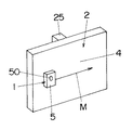
そこで、従来、合板や石膏ボードからなる壁材や天井材の背後にあって壁材や天井材を取り付ける胴縁、間柱、野縁等の支柱や、壁の背後に配設された水道管、電線管等を検知するための背後部材検知装置が知られている(例えば、特許文献1参照)。これは、壁材の背後における支柱の有無に応じて誘電率が変化することを利用し、静電容量の変化によって壁材の背後に配設された支柱を探知するものである。すなわち、図6に示すように、本体ケース5背面に電極板30を取り付け、図7の矢印Mで示す方向に本体ケース5を壁材2の表面4に沿って移動させ、電極板30に生じている電界が誘電率の変化に伴って変化することを利用して静電容量の変化を検出するのである。ここで、静電容量は図8に示すように、支柱25の中心位置で最大となるように変化する。静電容量が所定値以上であるとき発光ダイオードなどの表示素子50(図7)が点灯したり、発音素子が鳴動したりする。また、周囲の磁界、電界の強さの変化量を検出することで、壁の背後に配設された水道管や電線管を検知できるようにしている。
【0004】
【特許文献1】
特公平7−1313号公報
【0005】
【発明が解決しようとする課題】
しかしながら、従来の背後部材検知装置にあっては、本体ケースを壁材や天井材の表面に沿って走査させる必要があり、この場合、走査の際に壁材や天井材の表面を傷つけることなく走査させねばならない。ところが、壁材や天井材の表面は化粧シートを貼りつけたり、塗装を施すことによる表面仕上げがなされているため、様々な凹凸形状があり、壁材や天井材の表面に沿って本体ケースを走査させると凹凸面による摩擦などにより走査させづらいという問題がある。
【0006】
そこで、本発明者は本発明に至る過程で、壁材や天井材の表面を傷つけないようにするために、本体ケースにおける壁材や天井材の表面との接地面の全面に、走査性の妨げにならない程度に、壁材や天井材表面への傷つけ防止の保護シートを貼着することを考えた。
【0007】
ところが、壁材の背後における支柱の探知においては前述記載のとおり、壁材の背後における支柱の有無に応じて、電極板に生じている電界が誘電率の変化に伴って変化することを利用し、静電容量の変化を検知するため、電極板と壁材や天井材表面との間に、保護シート等の介在物があると前述の静電容量の検知精度が悪くなるという問題がある。
【0008】
本発明は、上記の従来例の問題点に鑑みて発明したものであって、その目的とするところは、壁材や天井材の表面を傷つけずに、しかも凹凸形状の摩擦などの影響を受けにくくし、壁材や天井材の背後部材の検知精度を保ったまま本体ケースの走査性を改善することができる背後部材検知装置を提供することにある。
【0009】
【課題を解決するための手段】
上記課題を解決するために本発明にあっては、壁材2や天井材の表面4に沿って走査される本体ケース5にセンサー部6を設け、壁材2等の背後に物体があるときに誘電率に差が生じることを利用して静電容量の変化を検出したり、或いは周囲の磁界、電界の強さの変化量を検出することで、物体の位置を探査する背後部材検知装置において、本体ケース5のセンサー部6周囲における壁材2等の表面4との接地面に、滑性を有する平坦面部分3を配設したことを特徴としており、このように構成することで、滑性を有する平坦面部分3を壁材2等の表面4に接地させるようにして本体ケース5を走査することにより、壁材2や天井材の表面4に化粧シートを貼りつけたり、塗装を施すことによる表面仕上げがなされている様々な凹凸形状を有する場合でも、滑性を有する平坦面部分3によって壁材2や天井材の表面4を傷つけることがなく、しかも、センサー部6は凹凸形状の摩擦などの影響を受けにくくなり、壁材2や天井材の背後部材の検知精度を高く維持できるようになる。
【0010】
また前記滑性を有する平坦面部分3を、本体ケース5の走査方向Aと平行な方向に細長く延ばすのが好ましく、この場合、滑性を有する平坦面部分3の面積を極力小さくしながら、走査性を高く維持できるようになる。
【0011】
また前記滑性を有する平坦面部分3の長手方向の両端部をアール状或いは鋭角状に形成するのが好ましく、この場合、壁材2や天井材の表面4を一層傷つけることがなく、しかも、電極板30は凹凸形状の摩擦などの影響を一層受けにくくなる。
【0012】
【発明の実施の形態】
以下、本発明を添付図面に示す実施形態に基づいて説明する。
【0013】
本実施形態のマーキング機能を有する背後部材検知装置1は、図1、図2に示すように、壁材2や天井材の表面4に沿って移動される本体ケース5に、壁材2等の背後に物体(背後部材)があるときに誘電率に差が生じることを利用して静電容量の変化を検出したり、或いは周囲の磁界、電界の強さの変化量を検出するためのセンサー部6を設け、センサー部6の出力値が所定基準値に達するとLED、ブザー等の報知手段により物体の位置を報知する構造に加えて、本体ケース5のセンサー部6周囲における壁材2等の表面4との接地面に、滑性を有する平坦面部分3を配設して構成されている。
【0014】
先ず、図3は背後部材検知装置1の本体ケース5内部の構成を示している。ここでは、周囲に形成した磁界の変動を電気信号に変換する第1のセンサー6Aと、周囲の誘電率に対応した電気信号が得られる第2のセンサー6Bと、第1のセンサー6Aと第2のセンサー6Bの各出力値が所定基準値に達すると各々出力が得られる動作制御回路21と、各動作制御回路21からの出力に応じて報知を行うブザー22や表示を行なうランプ等が配置された基板24とを具備したものであり、その詳細は従来例で説明した特公平7−1313号公報に開示されているものと同様である。
【0015】
上記背後部材検知装置1の探知機能は、壁材2(或いは天井材)の背後にある木材(間柱、胴縁など)、プラスチック(塩ビ管など)及び金属(鉄管、銅管など)の各種探知部材を探知するものである。ここで、木材、プラスチックの探知においては、壁材2の背後における木材などの支柱25(図7)の有無に応じて、誘電率が変化することを利用して、本体ケース5の背面側内部にある面状電極(図示せず)に生じる静電容量の変化量を検出する。なお、探知部材が木材の場合には、「木材浅(例えば壁材2の厚みが約13mmの場合)モード」と「木材深(例えば壁材2の厚みが約13〜25mmの場合)モード」とに切替えられ、壁材2の厚みに応じて使いわけられる。また金属の探知の場合は、金属が近づくと周囲に形成された磁界が変化することを利用して、本体ケース5内部に具備された金属センサーが電気信号の変化量を検出する。一方、活線警告機能は、電気が通っている電線(以下「活線」という。)が近くにあると、活線からでている電界を本体ケース5内部にある面状電極で電気信号に変換し電気信号の変化量を検出することによって、活線ランプを点灯させるものである。
【0016】
上記本体ケース5の下半部は、図2(a)に示すように、手で持ちやすいようにゴムグリップからなるグリップ部26が設けられており、グリップ部26の下端に設けた取付け部27には市販のストラップが取付け可能となっている。
【0017】
本体ケース5の前面中央には、電源のON,OFF及び探知スタート用スイッチを兼ねるメインスイッチ28が設けられている。メインスイッチ28の下側には「木材浅」「木材深」及び「金属専用」の探知モード切替スイッチ29が設けられている。メインスイッチ28の上側には、表示パネル23が設けられている。ここでは、LEDからなるランプa〜kが設けられている。ランプaは活線警告ランプであり、近くに活線があると点灯する)。ランプb,c,d,h,i,jは、探知レベルアップランプであり、支柱25の無いところから支柱25のあるところまで近づけていくと、ランプb,jが点灯し、続いてランプc,iが点灯し、続いてランプd,hが順に点灯するようになっている。ランプfは支柱25を探知したときに点灯する探知ランプである。ランプeは「木材浅」、「木材深」モードで使用時において支柱25を検知したら点灯する木材文字ランプである。ランプgは「金属専用」モードで使用時、金属を探知したときに点灯する金属文字ランプである。なお、金属文字ランプgは、「木材浅」「木材深」モードでの使用時において、支柱25(木材など)を探知し且つ金属も探知した場合にのみ点灯するものである。ランプk電池の容量が十分ある状態では点灯させ、容量が少なくなっている状態では点滅させ、ユーザに電池交換催促を告知する電池容量表示ランプである。
【0018】
本体ケース5の背面には、図1に示すように、電極板30が設けられ、電極板30の上下両側には、帯状をした滑性を有する平坦面部分3が設けられている。この滑性を有する平坦面部分3は、壁材2等の表面4に当たることができるように、本体ケース5の背面よりも若干突出している。ちなみに、壁材2(或いは天井材)の表面4は化粧シートを貼りつけたり、塗装を施すことによる表面仕上げがなされており、様々な凹凸形状を有しているため、電極板30の前後に滑性を有する平坦面部分3を配置することで、電極板30による検知精度を保ったまま、壁材2や天井材の表面4を傷つけずにしかも凹凸形状の摩擦などの影響を受けにくくすることができる構造となっている。なお滑性を有する平坦面部分3は、第2のセンサー6Bの上下両側に限られるものではなく、上下いずれか一方に設けられてもよい。また滑性を有する平坦面部分3の材質は、例えば滑性を有する合成樹脂や金属等が挙げられるが、特に問わない。また滑性を有する平坦面部分3は本体ケース5の背面と一体成形或いは別体のいずれであってもよい。
【0019】
さらに上記本体ケース5には、物体を探知したときに印をつけるためのガイドとなるマーキングガイド9aとマーキング用の開口部9とが設けられており、開口部9内にマーキング用の筆記具(例えば図3に示す鉛筆8)が挿入保持されるようになっている。
【0020】
次に、背後部材検知装置1の使用方法の一例を説明する。先ず、図1の電池蓋37を外して乾電池を入れた後、図2(a)のメインスイッチ28を長押し(約2秒)することにより電源をいれる。その後、探知モード切替スイッチ29によって探知モードに設定し、探知部材のある壁材2(図7)の表面4に本体ケース5の背面を当ててから、メインスイッチ28をワンプッシュする(初期設定)。その後、探知を開始する。先ず本体ケース5を壁材2に押し当てた状態で、一方向から壁材2の表面4に沿って滑らす。探知部材が近づくにつれ、レベルアップランプ(b,c,d,h,i,j)が両端点灯から中央点灯に移動する。そして、探知完了すると探知ランプが点灯する。このとき、マーキング作業を行なう。つまり、本体ケース5を保持しながら鉛筆8を押し込んで、孔40(図3)から芯を突出させて壁材2の表面4に印をつける。その後、上記一方向とは逆方向からの探知を開始し、上記と同じ手順で、初期設定〜マーキング作業までの操作を行なう。これにより、探知部材の中心位置を推測することができる。探知後はメインスイッチ28を長押し(約2秒)して電源を切る。
【0021】
しかして、本体ケース5の背面には、第2のセンサー6B周囲の接地面に滑性を有する平坦面部分3が配設され、この滑性を有する平坦面部分3を壁材2の表面4に接地させるようにして本体ケース5を走査するようにしたので、走査作業がスムーズとなり、しかも壁材2の表面4を傷つける心配がない。特に壁材2の表面4に化粧シートを貼りつけたり、塗装を施すことによる表面仕上げがなされている様々な凹凸形状を有する場合でも、滑性を有する平坦面部分3によって壁材2の表面4を傷つけることがなく、しかも、電極板30は凹凸形状の摩擦などの影響を受けにくくなり、走査性を改善できると共に、壁材2の背後部材の検知精度を高く維持できるようになる。このことは天井材の背後部材を探知する場合でも同様である。また本例では滑性を有する平坦面部分3は、電極板30の上下両側にそれぞれ設けられると共に、本体ケース5の走査方向Aに対して平行となるように細長く延びた帯状をしているので、滑性を有する平坦面部分3の面積を極力小さくしながら、走査性を高く維持できるようになる。
【0022】
なお、他の実施形態として図4に示すように、滑性を有する平坦面部分3の長手方向の両端部をアール状3aに形成したり、或いは図5に示すように、鋭角状3bに形成してもよい。いずれの場合も、平坦面部分3の端部によって壁材2や天井材の表面4を一層傷つけることがなく、しかも、電極板30は凹凸形状の摩擦などの影響を一層受けにくくなり、走査性をより改善できるものである。
【0023】
【発明の効果】
上述のように請求項1記載の発明にあっては、壁材や天井材の表面に沿って走査される本体ケースにセンサー部を設け、壁材等の背後に埋設物があるときに誘電率に差が生じることを利用して静電容量の変化を検出したり、或いは周囲の磁界、電界の強さの変化量を検出することで、埋設物の位置を探査する背後部材検知装置において、本体ケースのセンサー部周囲における壁材等の表面との接地面に、滑性を有する平坦面部分を配設したので、滑性を有する平坦面部分を壁材等の表面に接地させるようにして本体ケースを走査することにより、壁材や天井材の表面に化粧シートを貼りつけたり、塗装を施すことによる表面仕上げがなされている様々な凹凸形状を有する場合でも、滑性を有する平坦面部分によって壁材や天井材表面を傷つけることがなく、しかも、センサー部は凹凸形状の摩擦などの影響を受けにくくなり、壁材や天井材の背後部材の検知精度を高く維持しながら、走査性を改善できるものである。
【0024】
また請求項2記載の発明は、請求項1記載の効果に加えて、前記滑性を有する平坦面部分を、本体ケースの走査方向と平行な方向に細長く延ばしたので、滑性を有する平坦面部分の面積を極力小さくしながら、走査性を高く維持できるようになる。
【0025】
また請求項3記載の発明は、請求項2記載の効果に加えて、前記滑性を有する平坦面部分の長手方向の両端部をアール状或いは鋭角状に形成したので、壁材や天井材表面を一層傷つけることがなく、しかも、電極板は凹凸形状の摩擦などの影響を一層受けにくくなり、走査性をより改善できるものである。
【図面の簡単な説明】
【図1】本発明の一実施形態に用いる背後部材検知装置の本体ケースの背面図である。
【図2】(a)は同上の本体ケースの正面図、(b)は側面図である。
【図3】(a)は同上の本体ケース内部の構造を説明する正面図、(b)は側面断面図である。
【図4】他の実施形態の説明図である。
【図5】更に他の実施形態の説明図である。
【図6】従来例の説明図である。
【図7】従来の背後部材検知装置の使用状態の説明図である。
【図8】同上の支柱を検出した場合の静電容量の変化を示すグラフである。
【符号の説明】
1 背後部材検知装置
2 本体ケース
3 滑性を有する平坦面部分
3a アール状
3b 鋭角状
4 表面
6 センサー部
A 走査方向[0001]
TECHNICAL FIELD OF THE INVENTION
The present invention is a rim, a stud, a strut such as a ridge, and a water pipe provided behind a wall, which is provided behind a wall material or a ceiling material made of plywood or gypsum board, and which attaches the wall material or the ceiling material. BACKGROUND OF THE INVENTION 1. Field of the Invention The present invention relates to a back member detecting device for detecting a conduit or the like, and more particularly, to a technique for scanning a main body case without damaging the surface of a wall material or a ceiling material.
[0002]
[Prior art]
Generally, when the wall or ceiling is formed by wall material or ceiling material such as plywood or gypsum board, when attaching a clock, forehead, or handrail to the wall material, or when installing lighting on the wall material or ceiling material It is necessary to find out the support provided on the back of the wall material and ceiling material, and attach nails and hooks to the support, and when installing an air conditioner, etc. It is necessary to avoid and drill holes. However, since the surface of the wall material is generally finished by applying a decorative sheet or applying a paint, it is difficult to find out the position of the column by silent observation.
[0003]
Therefore, in the past, the hull rim, studs, stairs, etc., which are behind the wall material and ceiling material made of plywood and gypsum board and attach the wall material and ceiling material, and water pipes arranged behind the wall, BACKGROUND ART A back member detecting device for detecting a conduit or the like is known (for example, see Patent Document 1). This utilizes the fact that the permittivity changes depending on the presence or absence of a support behind the wall material, and detects a support provided behind the wall material by a change in capacitance. That is, as shown in FIG. 6, the electrode plate 30 is attached to the back of the main body case 5, and the main body case 5 is moved along the surface 4 of the wall material 2 in the direction indicated by the arrow M in FIG. The change in capacitance is detected by utilizing the fact that the applied electric field changes with the change in the dielectric constant. Here, as shown in FIG. 8, the capacitance changes so as to become maximum at the center position of the column 25. When the capacitance is equal to or more than a predetermined value, the display element 50 (FIG. 7) such as a light emitting diode is turned on or the sounding element is sounded. In addition, by detecting the amount of change in the intensity of the surrounding magnetic field and electric field, it is possible to detect a water pipe or a conduit installed behind a wall.
[0004]
[Patent Document 1]
Japanese Patent Publication No. Hei 7-1313
[Problems to be solved by the invention]
However, in the conventional back member detection device, it is necessary to scan the main body case along the surface of the wall material or the ceiling material.In this case, the surface of the wall material or the ceiling material is not damaged during scanning. You have to scan. However, since the surface of the wall and ceiling materials is finished by applying a decorative sheet or painting, it has various irregularities, and scans the main body case along the surface of the wall and ceiling materials In this case, there is a problem that scanning is difficult due to friction caused by the uneven surface.
[0006]
Therefore, in the process of reaching the present invention, the present inventor has proposed that the entire surface of the ground contact surface with the surface of the wall material or the ceiling material in the main body case should have a scantability so as not to damage the surface of the wall material or the ceiling material. We considered sticking a protective sheet to prevent damage to the wall and ceiling surfaces to the extent that it would not interfere.
[0007]
However, in the detection of the support behind the wall material, as described above, the fact that the electric field generated in the electrode plate changes with the change in the dielectric constant according to the presence or absence of the support behind the wall material is used. In order to detect a change in the capacitance, if there is an intervening material such as a protective sheet between the electrode plate and the surface of the wall material or ceiling material, there is a problem that the detection accuracy of the above-mentioned capacitance is deteriorated.
[0008]
The present invention has been made in view of the above-described problems of the conventional example, and has as its object to prevent the surface of a wall material or a ceiling material from being damaged and to be affected by friction of an uneven shape or the like. It is an object of the present invention to provide a back member detecting device which can improve the scanability of a main body case while maintaining the detection accuracy of a back member of a wall material or a ceiling material while maintaining the detection accuracy.
[0009]
[Means for Solving the Problems]
In order to solve the above-mentioned problem, in the present invention, a sensor unit 6 is provided on a main body case 5 scanned along the surface 4 of the wall material 2 or the ceiling material, and when an object is behind the wall material 2 or the like. Back member detection device that detects the position of an object by detecting the change in capacitance by utilizing the difference in the dielectric constant of the object, or detecting the amount of change in the intensity of the surrounding magnetic field and electric field. Is characterized in that a flat surface portion 3 having lubricity is disposed on a ground contact surface with the surface 4 such as the wall material 2 around the sensor section 6 of the main body case 5. By scanning the main body case 5 such that the smooth flat surface portion 3 is in contact with the surface 4 of the wall material 2 or the like, a decorative sheet is attached to the wall material 2 or the ceiling material 4 or painted. Various uneven shapes with surface finish In this case, the wall material 2 and the surface 4 of the ceiling material are not damaged by the flat surface portion 3 having lubricity, and the sensor portion 6 is hardly affected by the friction of the uneven shape. The detection accuracy of the member behind the ceiling material can be kept high.
[0010]
It is preferable that the flat surface portion 3 having lubricity is elongated in a direction parallel to the scanning direction A of the main body case 5. In this case, scanning is performed while minimizing the area of the flat surface portion 3 having lubricity. You can maintain high quality.
[0011]
Further, it is preferable that both ends in the longitudinal direction of the flat surface portion 3 having lubricity are formed in a round shape or an acute angle shape. In this case, the surface 4 of the wall material 2 or the ceiling material is not further damaged, and The electrode plate 30 is further less susceptible to the effects of friction of the uneven shape.
[0012]
BEST MODE FOR CARRYING OUT THE INVENTION
Hereinafter, the present invention will be described based on embodiments shown in the accompanying drawings.
[0013]
As shown in FIGS. 1 and 2, a back member detecting device 1 having a marking function according to the present embodiment includes a body case 5 that is moved along a surface 4 of a wall material 2 or a ceiling material. A sensor for detecting a change in capacitance or detecting a change in the strength of a surrounding magnetic field or electric field by utilizing a difference in dielectric constant when there is an object (back member) behind the object. In addition to the structure in which the position of the object is notified by the notification means such as the LED and the buzzer when the output value of the sensor unit 6 reaches a predetermined reference value, the wall material 2 around the sensor unit 6 of the main body case 5 is provided. A flat surface portion 3 having lubricity is disposed on a ground contact surface with the surface 4 of the device.
[0014]
First, FIG. 3 shows a configuration inside the main body case 5 of the back member detecting device 1. Here, a first sensor 6A that converts a fluctuation of a magnetic field formed around the sensor into an electric signal, a second sensor 6B that obtains an electric signal corresponding to the dielectric constant of the surrounding, a first sensor 6A, and a second sensor 6A. An operation control circuit 21 that obtains an output when each output value of the sensor 6B reaches a predetermined reference value, a buzzer 22 that performs notification in accordance with the output from each operation control circuit 21, a lamp that performs display, and the like are arranged. And the details thereof are the same as those disclosed in Japanese Patent Publication No. 7-1313 described in the related art.
[0015]
The detection function of the above-mentioned back member detection device 1 is to detect various types of wood (studs, rims, etc.), plastics (PVC pipes, etc.) and metals (iron pipes, copper pipes, etc.) behind the wall material 2 (or ceiling material). This is to detect a member. Here, in the detection of wood and plastic, the fact that the permittivity changes depending on the presence or absence of a support 25 (FIG. 7) made of wood or the like behind the wall material 2 makes use of the fact that the inside of the back side of the main body case 5 is used. The change amount of the capacitance generated in the planar electrode (not shown) is detected. When the detection member is wood, a “wood shallow (for example, when the thickness of the wall material 2 is about 13 mm) mode” and a “wood depth (for example, when the thickness of the wall material 2 is about 13 to 25 mm) mode” And are selectively used according to the thickness of the wall material 2. In the case of detecting a metal, a metal sensor provided inside the main body case 5 detects a change amount of an electric signal by utilizing a fact that a magnetic field formed around the metal changes when the metal approaches. On the other hand, when a live wire (hereinafter referred to as “hot wire”) is nearby, the hot-line warning function converts the electric field from the hot wire into an electric signal by the planar electrode inside the main body case 5. The hot-line lamp is turned on by detecting the amount of change in the electric signal after conversion.
[0016]
As shown in FIG. 2A, the lower half of the main body case 5 is provided with a grip portion 26 made of a rubber grip so as to be easily held by hand, and a mounting portion 27 provided at a lower end of the grip portion 26. A commercially available strap can be attached to.
[0017]
In the center of the front surface of the main body case 5, a main switch 28 also serving as a power ON / OFF and detection start switch is provided. Below the main switch 28, a detection mode changeover switch 29 for "shallow wood", "deep wood" and "metal only" is provided. A display panel 23 is provided above the main switch 28. Here, lamps a to k composed of LEDs are provided. Lamp a is a hot-line warning lamp, which lights up when there is a hot-line nearby. The lamps b, c, d, h, i, and j are detection level-up lamps, and when approaching from a place without the support 25 to a place with the support 25, the lamps b and j are turned on, and then the lamp c , I turn on, and then the lamps d, h turn on sequentially. The lamp f is a detection lamp that lights when the support 25 is detected. The lamp e is a wood character lamp which is turned on when the support 25 is detected in the "wood shallow" and "wood depth" modes. The lamp g is a metal character lamp that is turned on when a metal is detected in the “metal only” mode. Note that the metal character lamp g is turned on only when the support 25 (such as wood) is detected and metal is detected in the “wood shallow” or “wood deep” mode. Lamp k is a battery capacity display lamp that lights when the battery has a sufficient capacity, blinks when the capacity is low, and notifies the user of a battery replacement reminder.
[0018]
As shown in FIG. 1, an electrode plate 30 is provided on the back surface of the main body case 5, and strip-shaped smooth surface portions 3 are provided on both upper and lower sides of the electrode plate 30. The flat surface portion 3 having lubricity slightly protrudes from the back surface of the main body case 5 so as to be able to hit the surface 4 such as the wall material 2. By the way, the surface 4 of the wall material 2 (or ceiling material) is finished by applying a decorative sheet or painting, and has various irregularities. By arranging the flat surface portion 3 having the property, the detection accuracy by the electrode plate 30 is maintained, the wall material 2 and the surface 4 of the ceiling material are not damaged, and the influence of the friction of the uneven shape is reduced. It has a structure that can be. Note that the flat surface portion 3 having lubricity is not limited to the upper and lower sides of the second sensor 6B, but may be provided on one of the upper and lower sides. The material of the flat surface portion 3 having lubricity is, for example, a synthetic resin or metal having lubricity, but is not particularly limited. Further, the flat surface portion 3 having lubricity may be formed integrally with the rear surface of the main body case 5 or may be formed separately.
[0019]
Further, the main body case 5 is provided with a marking guide 9a serving as a guide for making a mark when an object is detected and an opening 9 for marking. In the opening 9, a writing instrument for marking (for example, A pencil 8) shown in FIG. 3 is inserted and held.
[0020]
Next, an example of a method of using the back member detecting device 1 will be described. First, after removing the battery cover 37 of FIG. 1 and inserting a dry battery, the power is turned on by long-pressing (about 2 seconds) the main switch 28 of FIG. 2A. Thereafter, the detection mode is set to the detection mode by the detection mode changeover switch 29, and the back of the main body case 5 is brought into contact with the surface 4 of the wall member 2 (FIG. 7) having the detection member, and then the main switch 28 is pushed one time (initial setting). . After that, detection is started. First, the main body case 5 is slid along the surface 4 of the wall material 2 from one direction while being pressed against the wall material 2. As the detection member approaches, the level-up lamps (b, c, d, h, i, j) move from lighting at both ends to lighting at the center. When the detection is completed, the detection lamp is turned on. At this time, a marking operation is performed. That is, the pencil 8 is pushed in while holding the main body case 5, and the core is projected from the hole 40 (FIG. 3) to mark the surface 4 of the wall material 2. Thereafter, the detection from the direction opposite to the one direction is started, and the operations from the initial setting to the marking operation are performed in the same procedure as described above. Thereby, the center position of the detection member can be estimated. After the detection, the power is turned off by long-pressing the main switch 28 (about 2 seconds).
[0021]
Thus, on the back surface of the main body case 5, a flat surface portion 3 having lubricity is provided on the grounding surface around the second sensor 6B, and the flat surface portion 3 having lubricity is attached to the surface 4 of the wall material 2. Since the main body case 5 is scanned so as to be grounded, the scanning operation becomes smooth and there is no fear that the surface 4 of the wall material 2 is damaged. In particular, even if the decorative sheet is applied to the surface 4 of the wall material 2 or has various irregularities which are finished by applying a paint, the surface 4 of the wall material 2 is smoothened by the flat surface portion 3 having lubricity. There is no damage, and the electrode plate 30 is less susceptible to friction due to the uneven shape, so that the scanability can be improved and the detection accuracy of the member behind the wall member 2 can be maintained at a high level. The same applies to the case where the member behind the ceiling material is detected. Further, in this example, the flat surface portions 3 having lubricity are provided on both upper and lower sides of the electrode plate 30, respectively, and have a strip shape elongated so as to be parallel to the scanning direction A of the main body case 5. In addition, it is possible to maintain high scannability while minimizing the area of the smooth flat surface portion 3.
[0022]
As another embodiment, as shown in FIG. 4, both ends in the longitudinal direction of the smooth flat surface portion 3 are formed in a round shape 3a, or as shown in FIG. 5, formed in an acute angle shape 3b. May be. In any case, the end of the flat surface portion 3 does not further damage the wall material 2 or the surface 4 of the ceiling material, and the electrode plate 30 is less susceptible to the friction of the uneven shape, and the scanning performance is improved. Can be further improved.
[0023]
【The invention's effect】
As described above, according to the first aspect of the present invention, a sensor unit is provided on a main body case that is scanned along the surface of a wall material or a ceiling material, and when a buried object is behind a wall material or the like, a dielectric constant is provided. In the back member detection device that detects the position of the buried object by detecting the change in capacitance using the difference that occurs, or by detecting the amount of change in the intensity of the surrounding magnetic field and electric field, Since a flat surface portion having lubricity is disposed on the ground surface with the surface of the wall material or the like around the sensor section of the main body case, the flat surface portion having lubricity is grounded to the surface of the wall material or the like. By scanning the main body case, you can paste a decorative sheet on the surface of wall material or ceiling material, even if it has various uneven shapes that are finished by applying paint, even if it has a smooth flat surface part Damages wall and ceiling surfaces It is no, moreover, the sensor unit is hardly affected by the friction of irregular shape, while maintaining a high detection accuracy behind member wall materials and ceiling materials, in which can be improved scanning properties.
[0024]
According to a second aspect of the present invention, in addition to the effect of the first aspect, the smooth flat surface portion is elongated in a direction parallel to the scanning direction of the main body case. It is possible to maintain high scannability while minimizing the area of the portion.
[0025]
According to the third aspect of the present invention, in addition to the effect of the second aspect, both ends in the longitudinal direction of the flat surface portion having lubricity are formed in a round shape or an acute angle shape, so that the surface of the wall material or the ceiling material is formed. The electrode plate is not further damaged, and the electrode plate is further less affected by the friction of the uneven shape, so that the scanability can be further improved.
[Brief description of the drawings]
FIG. 1 is a rear view of a main body case of a back member detecting device used in an embodiment of the present invention.
2A is a front view of the main body case, and FIG. 2B is a side view.
FIG. 3A is a front view illustrating the internal structure of the main body case, and FIG. 3B is a side cross-sectional view.
FIG. 4 is an explanatory diagram of another embodiment.
FIG. 5 is an explanatory diagram of still another embodiment.
FIG. 6 is an explanatory diagram of a conventional example.
FIG. 7 is an explanatory diagram of a use state of a conventional back member detection device.
FIG. 8 is a graph showing a change in capacitance when the support is detected.
[Explanation of symbols]
DESCRIPTION OF SYMBOLS 1 Back member detection device 2 Main body case 3 Flat surface portion 3a having a smoothness 3a radius 3b acute angle 4 surface 6 sensor part A scanning direction