【0001】
【発明の属する技術分野】
本発明は、斜板式の回転ピストンポンプやモータに用いられる軸受規制装置に係り、一層詳細には斜板と支持部材との間に介装するローラベアリング等軸受の保持手段に関する。
【0002】
【従来の技術】
斜板式の回転ピストンポンプやモータに用いられる斜板には、例えば背面部を半円筒形に形成し、後方の支持部材に形成した同形の凹部とこの背面部との間にローラベアリングを介装することで、斜板を半円筒形の周方向に変位可能に支持したものがある。この場合に、ローラベアリングが振動や衝撃によりずれたり、抜け落ちたりしないよう、斜板と支持部材との間に適正に保持する必要があり、このために従来では、例えば図3及び図4に示すような軸受規制装置が提案されている(例えば、特許文献1参照)。
【0003】
これは、回転するピストン(図示せず)に当接してピストンを伸縮駆動する斜板100の背面部100aを半円筒形に形成し、この背面部100aの後方に相対して同形の凹面部101aを備えた支持部材101を設け、これらの背面部100aと凹面部101aとの間に弧形に湾曲する支持枠102に支持されたローラベアリング103を挾持する構造の斜板ポンプ又はモータにおいて、斜板100の回転中心Oよりも前方側からローラベアリング103の支持枠側に伸びる保持ロッド104を設け、保持ロッド104の一端104aをローラベアリング103の支持枠102に形成した切欠105に係合し、保持ロッド104の中間部を斜板100の側面にピン106を介して回転自由に支持し、保持ロッド104のもう一端104bを斜板100の回転中心Oよりも前方側にて支持部材101と一体のケーシング107の内側面又はケーシング107の蓋部に回転自由に支持したものである。
【0004】
従って、レバー108の駆動により斜板100を図3の実線位置から鎖線に示す方向へ回動すると、保持ロッド104は一端104bを固定回転支点に中間部が図の下方に向かって変位すると共に、これに伴い保持ロッド104のもう一端(先端)104aが変位しつつ、斜板100と同方向へ動く支持枠102の変位を案内する。この保持ロッド104の動作に伴う中間部のロッド軸方向の変位は、ピン106部における滑動可能回転支点により吸収される。
【0005】
そして、これによれば、ケーシング107の内側面又はケーシング107の蓋部並びに斜板100の側面に保持ロッド104を支持して、ローラベアリング103の支持枠102を保持するため、ローラベアリング103の背面支持部(支持部材101)の加工の必要がなく、ローラベアリング103の支持枠102に形成した切欠105に一端104aを係合するため、その端部の加工の必要もなく、また保持ロッド104の支持部を斜板100の側面並びにケーシング107の内側面又はケーシング107の蓋部つまり斜板100の背面側でなく前方側に設けるため、組付けが容易になるとある。
【0006】
【特許文献1】
特開平9−264245号公報
【0007】
【発明が解決しようとする課題】
ところが、図3及び図4に示した軸受規制装置にあっては、斜板100の側面に回転自由に支持されたピン106が、支持枠102を支持する保持ロッド104を滑動可能に貫通支持する構造であるため、ピン106部において機能が重複し拗れ等により作動の円滑性に難点があることから、装置の信頼性に欠けるという問題点があった。
【0008】
そこで、本発明は、構造の簡略化により装置の信頼性を高めることができる斜板ポンプ又はモータの軸受規制装置を提供することを目的としている。
【0009】
【課題を解決するための手段】
前記課題を解決する請求項1の発明は、回転するピストンに当接してピストンを伸縮駆動する斜板の背面部を半円筒形に形成し、この背面部の後方に相対して同形の凹面部を備えた支持部材を設け、これらの背面部と凹面部との間に転がり又はすべり軸受を挾持する構造の斜板ポンプ又はモータにおいて、前記斜板と転がり又はすべり軸受と支持部材とに亙って伸びる保持ロッドを設け、該保持ロッドの一端をロッド軸線と直角方向に折曲して前記斜板の側面に形成した嵌合穴に回転自由に嵌合し、保持ロッドの中間部を前記転がり又はすべり軸受の支持部に形成したスリットに遊嵌し、保持ロッドの他端を長手方向に偏平なリング状に屈曲してこのリング状部内にケース側に植設されて前記ロッド軸線と直角方向に突出するピンを遊嵌したことを特徴とする。
【0010】
請求項2の発明は、前記スリットの内面は楔状か或いは円弧状に形成され、斜板の傾転角が零ではスリットと保持ロッドの間に所定の隙間を有し、斜板の傾転角の増加に伴い前記隙間が減少するように設定されていることを特徴とする。
【0011】
請求項3の発明は、前記リング状部の大きさは、可及的に斜板の傾動方向のガタを少なくして斜板の傾転角が零から最大までピン上を自由に滑動できるように設定されていることを特徴とする。
【0012】
【発明の実施の形態】
以下、本発明に係る斜板ポンプ又はモータの軸受規制装置を実施例により図面を用いて詳細に説明する。
【0013】
[実施例]
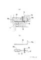
図1は本発明の一実施例を示す斜板ポンプ又はモータの要部断面図で、その上半部が縦(垂直)断面図で下半部が横(水平)断面図であり、図2の(a)は図1の要部拡大断面図で、図2の(b)は保持ロッドの説明図である。
【0014】
図1に示すように、斜板ポンプ又はモータ1はシャフト2に支承したシリンダーブロック3を備え、前記シャフト2は当該斜板ポンプ又はモータ1がポンプとして或いはモータとして作用するかによって駆動軸或いは入力軸になる。また、シャフト2は、3部分4,5,6によってのみ代表した当該斜板ポンプ又はモータ1のケース内でベアリング7により回動可能に支持されている。
【0015】
前記シリンダーブロック3は、斜板8上のソケット部材9に係合するピストン10のためのシリンダーを形成するボア11を有する。このボア11内のピストン10のストロークは、周知のようにシャフト2の軸に関して斜板8の上下角(傾転角)を調整することにより可変され得る。その調整は、シャフト2の軸上のリテーナボール12を中心として例えば斜板8に固定されかつ図示しない調整装置により傾動されるレバーアーム13により行い得る。
【0016】
前記斜板8の背面部8aは半円筒形に形成され、この背面部8aの後方に相対して同形の凹面部14aを備えた支持部材14が設けられ、これらの背面部8aと凹面部14aとの間に弧形に湾曲する支持枠(支持部)15に支持されたローラベアリング16が挾持される。
【0017】
そして、図2に示すように、前記支持枠15の外側面に形成されたスリット17内に前記シャフト2の軸方向に伸びる保持ロッド18が遊嵌される。この保持ロッド18の一端18aは90°に折曲されて前記斜板8の側面に形成した嵌合穴19に回動自由に嵌合されると共に、保持ロッド18の他端は長手方向に偏平なリング状に屈曲されてこのリング状部18b内にケース4に植設されて前記シャフト2の軸方向と直角方向に突出するピン20が遊嵌される。
【0018】
また、前記スリット17の内面は楔状か或いは円弧状(図示例では楔状)に形成され、斜板8の傾転角が零ではスリット17と保持ロッド18の間に所定の隙間を有し、斜板8の傾転角の増加に伴い前記隙間が減少するように設定されている。
【0019】
また、前記リング状部18bの大きさは、可及的に斜板8の傾動方向のガタを少なくして斜板8の傾転角が零から最大までピン20上を自由に滑動できるように設定される。
【0020】
尚、図1中21は、ケース4に付設されて斜板8の最大傾転角を規制するストッパである。
【0021】
このように構成されるため、レバーアーム13の駆動により斜板8を図1の実線位置から鎖線に示す方向へ回動すると、保持ロッド18はその一端18aを移動回転支点に中間部がスリット17内を滑動変位すると共に、これに伴い保持ロッド18のリング状部18bがピン20上を変位しつつ、斜板8と同方向へ動く支持枠15の変位を案内する。
【0022】
斜板8の傾転角が最大になると、保持ロッド18のリング状部18bがピン20に係合してそれ以上の変位が不能となり、該保持ロッド18の中間部にスリット17を介して係合した支持枠15もそれ以上の変位が阻止される。即ち、この支持枠15に保持されたローラベアリング16が、振動や衝撃によりずれたり、抜け落ちたりしないよう、斜板8と支持部材14との間に適正に保持されるのである。
【0023】
そして、本実施例では、前記斜板8の傾転角の増加に伴い前記スリット17と保持ロッド18間の隙間が減少するようになっているので、保持ロッド18の傾転角が大きくなる場合のふれ角を小さくすることができる。
【0024】
また、保持ロッド18と該保持ロッド18が関わり合う斜板8,支持枠15,ピン20とは単一機能でそれぞれ関わっているので、拗れ等により作動の円滑性が損なわれることがなく、装置の信頼性が高い。
【0025】
また、従来例のピン106(図3参照)と保持ロッド104(図3参照)の関係のように、貫通部品がないので、構造が簡単になり、装置の信頼性が高いと共に組み立ても容易である。
【0026】
尚、本発明は上記実施例に限定されず、本発明の要旨を逸脱しない範囲で各種変更が可能であることはいうまでもない。例えば、支持枠15とローラベアリング16とからなる転がり軸受の代わりにすべり軸受(スペーサ)を設け、このすべり軸受の一部を支持枠とみなして保持ロッド18で案内するようにしても良い。また、支持部材14とケース4とを一体に形成しても良い。
【0027】
【発明の効果】
以上説明したように、請求項1の発明は、回転するピストンに当接してピストンを伸縮駆動する斜板の背面部を半円筒形に形成し、この背面部の後方に相対して同形の凹面部を備えた支持部材を設け、これらの背面部と凹面部との間に転がり又はすべり軸受を挾持する構造の斜板ポンプ又はモータにおいて、前記斜板と転がり又はすべり軸受と支持部材とに亙って伸びる保持ロッドを設け、該保持ロッドの一端をロッド軸線と直角方向に折曲して前記斜板の側面に形成した嵌合穴に回転自由に嵌合し、保持ロッドの中間部を前記転がり又はすべり軸受の支持部に形成したスリットに遊嵌し、保持ロッドの他端を長手方向に偏平なリング状に屈曲してこのリング状部内にケース側に植設されて前記ロッド軸線と直角方向に突出するピンを遊嵌したので、構造の簡略化により組付性の向上と装置の信頼性を高めることができる。
【0028】
請求項2の発明は、前記スリットの内面は楔状か或いは円弧状に形成され、斜板の傾転角が零ではスリットと保持ロッドの間に所定の隙間を有し、斜板の傾転角の増加に伴い前記隙間が減少するように設定されているので、保持ロッドの傾転角が大きくなる場合のふれ角を小さくすることができる。
【0029】
請求項3の発明は、前記リング状部の大きさは、可及的に斜板の傾動方向のガタを少なくして斜板の傾転角が零から最大までピン上を自由に滑動できるように設定されているので、ラフな設計で作動の円滑性を保持できる。
【図面の簡単な説明】
【図1】本発明の一実施例を示す斜板ポンプ又はモータの要部断面図で、その上半部が縦(垂直)断面図で下半部が横(水平)断面図である。
【図2】同図(a)は図1の要部拡大断面図で、同図(b)は保持ロッドの説明図である。
【図3】従来の斜板ポンプ又はモータの要部断面図である。
【図4】図3の異なった部分斜視図である。
【符号の説明】
1 斜板ポンプ又はモータ、2 シャフト、3 シリンダーブロック、4 ケース、5 ケース、6 ケース、7 ベアリング、8 斜板、8a 背面部、9ソケット部材、10 ピストン、11 ボア、12 リテーナボール、13 レバーアーム、14 支持部材、14a 凹面部、15 支持枠、16 ローラベアリング、17 スリット、18 保持ロッド、18a 保持ロッドの一端、18b リング状部(保持ロッドの他端)、19 嵌合穴、20 ピン。[0001]
TECHNICAL FIELD OF THE INVENTION
The present invention relates to a bearing control device used in a swash plate type rotary piston pump or motor, and more particularly to a bearing holding device such as a roller bearing interposed between a swash plate and a support member.
[0002]
[Prior art]
In a swash plate used in a swash plate type rotary piston pump or motor, for example, a rear portion is formed in a semi-cylindrical shape, and a roller bearing is interposed between the same concave portion formed in a rear support member and the rear portion. In some cases, the swash plate is supported so as to be displaceable in a semi-cylindrical circumferential direction. In this case, it is necessary to appropriately hold the roller bearing between the swash plate and the support member so that the roller bearing does not shift or fall off due to vibration or impact. For this reason, conventionally, for example, as shown in FIGS. Such a bearing control device has been proposed (for example, see Patent Document 1).
[0003]
This is because a back surface 100a of a swash plate 100 which contacts a rotating piston (not shown) to extend and contract the piston is formed in a semi-cylindrical shape, and a concave surface portion 101a of the same shape is formed opposite the rear surface 100a. A swash plate pump or motor having a structure in which a roller bearing 103 supported by a support frame 102 curved in an arc shape is sandwiched between a back surface portion 100a and a concave surface portion 101a. A holding rod 104 extending from the front side of the rotation center O of the plate 100 to the support frame side of the roller bearing 103 is provided, and one end 104a of the holding rod 104 is engaged with a notch 105 formed in the support frame 102 of the roller bearing 103, The intermediate portion of the holding rod 104 is rotatably supported on the side surface of the swash plate 100 via a pin 106, and the other end 104b of the holding rod 104 is Than the rotation center O of the plate 100 is obtained by rotatably supporting the lid portion of the inner surface or casing 107 of the supporting member 101 integral with the casing 107 at the front side.
[0004]
Accordingly, when the swash plate 100 is rotated in the direction shown by the dashed line from the solid line position in FIG. 3 by driving the lever 108, the holding rod 104 is displaced downward at the intermediate portion with the one end 104b at the fixed rotation fulcrum. Accordingly, while the other end (tip) 104a of the holding rod 104 is displaced, it guides the displacement of the support frame 102 moving in the same direction as the swash plate 100. The displacement of the intermediate portion in the rod axial direction accompanying the operation of the holding rod 104 is absorbed by the slidable rotation fulcrum at the pin 106.
[0005]
According to this, the holding rod 104 is supported on the inner surface of the casing 107 or the lid of the casing 107 and the side surface of the swash plate 100 to hold the support frame 102 of the roller bearing 103. There is no need to process the support portion (support member 101), and the one end 104a is engaged with the notch 105 formed in the support frame 102 of the roller bearing 103. Since the support portion is provided not on the side surface of the swash plate 100 and on the inner surface of the casing 107 or on the cover portion of the casing 107, that is, on the front side but on the rear side of the swash plate 100, assembly may be facilitated.
[0006]
[Patent Document 1]
JP-A-9-264245
[Problems to be solved by the invention]
However, in the bearing control device shown in FIGS. 3 and 4, the pin 106 rotatably supported on the side surface of the swash plate 100 slidably penetrates and holds the holding rod 104 that supports the support frame 102. Due to the structure, the function is duplicated at the pin 106 and there is a problem in smoothness of operation due to stiffness or the like, so that there is a problem that the reliability of the device is lacking.
[0008]
Accordingly, it is an object of the present invention to provide a swash plate pump or motor bearing restricting device capable of improving the reliability of the device by simplifying the structure.
[0009]
[Means for Solving the Problems]
According to a first aspect of the present invention, a back surface of a swash plate that contacts a rotating piston and drives the piston to expand and contract is formed into a semi-cylindrical shape, and a concave surface of the same shape is formed opposite to the back surface of the swash plate. A swash plate pump or motor having a structure in which a rolling or sliding bearing is sandwiched between a back surface portion and a concave surface portion of the swash plate, the rolling or sliding bearing and the supporting member are provided. A holding rod extending in a direction perpendicular to the rod axis, and rotatably fitted in a fitting hole formed in a side surface of the swash plate, and the intermediate portion of the holding rod is rolled. Or, it is loosely fitted in the slit formed in the support portion of the slide bearing, the other end of the holding rod is bent in a flat ring shape in the longitudinal direction, and is implanted in the ring-shaped portion on the case side in a direction perpendicular to the rod axis. The projecting pin is loosely fitted And wherein the door.
[0010]
The invention according to claim 2 is that the inner surface of the slit is formed in a wedge shape or an arc shape, and when the tilt angle of the swash plate is zero, there is a predetermined gap between the slit and the holding rod, and the tilt angle of the swash plate The gap is set so as to decrease as the number increases.
[0011]
According to a third aspect of the present invention, the size of the ring-shaped portion is such that the play in the tilting direction of the swash plate is reduced as much as possible so that the tilt angle of the swash plate can freely slide on the pin from zero to the maximum. Is set to.
[0012]
BEST MODE FOR CARRYING OUT THE INVENTION
DETAILED DESCRIPTION OF THE PREFERRED EMBODIMENTS Hereinafter, a swash plate pump or motor bearing restricting device according to the present invention will be described in detail with reference to the drawings using embodiments.
[0013]
[Example]
FIG. 1 is a sectional view of a main part of a swash plate pump or a motor according to an embodiment of the present invention, in which an upper half is a vertical (vertical) sectional view and a lower half is a horizontal (horizontal) sectional view. 2A is an enlarged sectional view of a main part of FIG. 1, and FIG. 2B is an explanatory view of a holding rod.
[0014]
As shown in FIG. 1, the swash plate pump or motor 1 has a cylinder block 3 supported on a shaft 2, and the shaft 2 has a drive shaft or an input depending on whether the swash plate pump or motor 1 acts as a pump or a motor. Become an axis. The shaft 2 is rotatably supported by a bearing 7 in the case of the swash plate pump or the motor 1 represented only by three portions 4, 5, and 6.
[0015]
Said cylinder block 3 has a bore 11 which forms a cylinder for a piston 10 which engages a socket member 9 on a swash plate 8. The stroke of the piston 10 in the bore 11 can be changed by adjusting the vertical angle (tilt angle) of the swash plate 8 with respect to the axis of the shaft 2 as is well known. The adjustment can be performed by a lever arm 13 fixed to, for example, the swash plate 8 about the retainer ball 12 on the axis of the shaft 2 and tilted by an adjusting device (not shown).
[0016]
The back portion 8a of the swash plate 8 is formed in a semi-cylindrical shape, and a support member 14 having a concave portion 14a of the same shape is provided behind the back portion 8a, and the back portion 8a and the concave portion 14a are provided. A roller bearing 16 supported by a support frame (supporting portion) 15 that is curved in an arc shape is sandwiched therebetween.
[0017]
Then, as shown in FIG. 2, a holding rod 18 extending in the axial direction of the shaft 2 is loosely fitted in a slit 17 formed on the outer surface of the support frame 15. One end 18a of the holding rod 18 is bent at 90 ° and is rotatably fitted in a fitting hole 19 formed in the side surface of the swash plate 8, and the other end of the holding rod 18 is flattened in the longitudinal direction. A pin 20 that is bent into a ring shape, is implanted in the case 4 in the ring-shaped portion 18b, and projects in a direction perpendicular to the axial direction of the shaft 2 is loosely fitted.
[0018]
The inner surface of the slit 17 is formed in a wedge shape or an arc shape (a wedge shape in the illustrated example). When the tilt angle of the swash plate 8 is zero, there is a predetermined gap between the slit 17 and the holding rod 18. The gap is set so as to decrease as the tilt angle of the plate 8 increases.
[0019]
The size of the ring-shaped portion 18b is set so that the play in the tilting direction of the swash plate 8 is reduced as much as possible so that the tilt angle of the swash plate 8 can freely slide on the pin 20 from zero to the maximum. Is set.
[0020]
In FIG. 1, reference numeral 21 denotes a stopper attached to the case 4 to limit the maximum tilt angle of the swash plate 8.
[0021]
With this configuration, when the swash plate 8 is rotated in the direction shown by the dashed line from the solid line position in FIG. While sliding inside, the ring-shaped portion 18 b of the holding rod 18 guides the displacement of the support frame 15 moving in the same direction as the swash plate 8 while displacing on the pin 20.
[0022]
When the tilt angle of the swash plate 8 is maximized, the ring-shaped portion 18b of the holding rod 18 is engaged with the pin 20 and no further displacement is possible. The combined support frame 15 also prevents further displacement. That is, the roller bearing 16 held by the support frame 15 is properly held between the swash plate 8 and the support member 14 so that the roller bearing 16 does not shift or fall off due to vibration or impact.
[0023]
In the present embodiment, the gap between the slit 17 and the holding rod 18 decreases as the tilt angle of the swash plate 8 increases, so that the tilt angle of the holding rod 18 increases. Can be reduced.
[0024]
Further, since the holding rod 18 and the swash plate 8, the support frame 15, and the pin 20 with which the holding rod 18 is related are each associated with a single function, the smoothness of operation is not impaired due to stiffness or the like. High device reliability.
[0025]
Further, since there is no penetrating part as in the relationship between the pin 106 (see FIG. 3) and the holding rod 104 (see FIG. 3) of the conventional example, the structure is simplified, the reliability of the device is high, and the assembly is easy. is there.
[0026]
It is needless to say that the present invention is not limited to the above embodiments, and various changes can be made without departing from the spirit of the present invention. For example, a sliding bearing (spacer) may be provided instead of the rolling bearing composed of the support frame 15 and the roller bearing 16, and a part of the sliding bearing may be regarded as the support frame and guided by the holding rod 18. Further, the support member 14 and the case 4 may be formed integrally.
[0027]
【The invention's effect】
As described above, according to the first aspect of the present invention, the rear surface of the swash plate that contacts the rotating piston and drives the piston to expand and contract is formed in a semi-cylindrical shape, and the concave surface of the same shape is formed opposite to the rear of the rear surface. A swash plate pump or motor having a structure in which a supporting member having a portion is provided, and a rolling or sliding bearing is sandwiched between the back surface and the concave portion, the swash plate, the rolling or sliding bearing, and the supporting member. A holding rod extending in a direction perpendicular to the rod axis, and rotatably fitted into a fitting hole formed in a side surface of the swash plate. The other end of the holding rod is bent into a flat ring shape in the longitudinal direction and is implanted on the case side in the ring-shaped portion, and is perpendicular to the rod axis. Insert the pin that projects in the direction Since, it is possible to improve the reliability of the assembly improvement and apparatus by simplifying the structure.
[0028]
The invention according to claim 2 is that the inner surface of the slit is formed in a wedge shape or an arc shape, and when the tilt angle of the swash plate is zero, there is a predetermined gap between the slit and the holding rod, and the tilt angle of the swash plate The clearance is set so as to decrease as the distance increases, so that the deflection angle when the tilt angle of the holding rod increases can be reduced.
[0029]
According to a third aspect of the present invention, the size of the ring-shaped portion is such that the play in the tilting direction of the swash plate is reduced as much as possible so that the tilt angle of the swash plate can freely slide on the pin from zero to the maximum. , The operation can be kept smooth with a rough design.
[Brief description of the drawings]
FIG. 1 is a sectional view of a main part of a swash plate pump or a motor according to an embodiment of the present invention, in which an upper half is a vertical (vertical) sectional view and a lower half is a horizontal (horizontal) sectional view.
2 (a) is an enlarged sectional view of a main part of FIG. 1, and FIG. 2 (b) is an explanatory view of a holding rod.
FIG. 3 is a sectional view of a main part of a conventional swash plate pump or motor.
FIG. 4 is a different partial perspective view of FIG. 3;
[Explanation of symbols]
1 Swash plate pump or motor, 2 shafts, 3 cylinder blocks, 4 cases, 5 cases, 6 cases, 7 bearings, 8 swash plates, 8a back surface, 9 socket members, 10 pistons, 11 bores, 12 retainer balls, 13 levers Arm, 14 support member, 14a concave portion, 15 support frame, 16 roller bearing, 17 slit, 18 holding rod, 18a one end of holding rod, 18b ring-shaped portion (other end of holding rod), 19 fitting hole, 20 pin .