JP2004178590A - Address range comparator for detecting memory accesses of multi sizes by data matching qualification and full or partial ovrlap - Google Patents
Address range comparator for detecting memory accesses of multi sizes by data matching qualification and full or partial ovrlap Download PDFInfo
- Publication number
- JP2004178590A JP2004178590A JP2003392615A JP2003392615A JP2004178590A JP 2004178590 A JP2004178590 A JP 2004178590A JP 2003392615 A JP2003392615 A JP 2003392615A JP 2003392615 A JP2003392615 A JP 2003392615A JP 2004178590 A JP2004178590 A JP 2004178590A
- Authority
- JP
- Japan
- Prior art keywords
- address
- data
- memory access
- comparator
- memory
- Prior art date
- Legal status (The legal status is an assumption and is not a legal conclusion. Google has not performed a legal analysis and makes no representation as to the accuracy of the status listed.)
- Pending
Links
Images


Classifications
-
- G—PHYSICS
- G06—COMPUTING; CALCULATING OR COUNTING
- G06F—ELECTRIC DIGITAL DATA PROCESSING
- G06F11/00—Error detection; Error correction; Monitoring
- G06F11/36—Preventing errors by testing or debugging software
- G06F11/362—Software debugging
- G06F11/3648—Software debugging using additional hardware
-
- G—PHYSICS
- G01—MEASURING; TESTING
- G01R—MEASURING ELECTRIC VARIABLES; MEASURING MAGNETIC VARIABLES
- G01R31/00—Arrangements for testing electric properties; Arrangements for locating electric faults; Arrangements for electrical testing characterised by what is being tested not provided for elsewhere
- G01R31/28—Testing of electronic circuits, e.g. by signal tracer
- G01R31/317—Testing of digital circuits
- G01R31/31703—Comparison aspects, e.g. signature analysis, comparators
-
- G—PHYSICS
- G01—MEASURING; TESTING
- G01R—MEASURING ELECTRIC VARIABLES; MEASURING MAGNETIC VARIABLES
- G01R31/00—Arrangements for testing electric properties; Arrangements for locating electric faults; Arrangements for electrical testing characterised by what is being tested not provided for elsewhere
- G01R31/28—Testing of electronic circuits, e.g. by signal tracer
- G01R31/317—Testing of digital circuits
- G01R31/31705—Debugging aspects, e.g. using test circuits for debugging, using dedicated debugging test circuits
-
- G—PHYSICS
- G06—COMPUTING; CALCULATING OR COUNTING
- G06F—ELECTRIC DIGITAL DATA PROCESSING
- G06F11/00—Error detection; Error correction; Monitoring
- G06F11/36—Preventing errors by testing or debugging software
- G06F11/362—Software debugging
- G06F11/3648—Software debugging using additional hardware
- G06F11/3656—Software debugging using additional hardware using a specific debug interface
Abstract
Description
本発明は、特に高度集積ディジタル信号処理システムのためのエミュレーション・ハードウエアに関し、特にデータ一致認定(クオリフィケーション)および完全または部分的重複(オーバーラップ)によって、多数のサイズのメモリ・アクセスを検出するアドレス範囲比較器に関する。 The present invention relates to emulation hardware, especially for highly integrated digital signal processing systems, and detects multiple sizes of memory accesses, particularly by data match qualification and full or partial overlap. Address range comparator.
高度なウエハ・リソグラフィおよび表面実装パッケージング技術は、電子的設計のシリコン・レベルおよびプリント回路基板レベル双方において、増々複雑な機能を統合しつつある。しかしながら、設計密度が高まり、相互接続ピッチが狭くなったことの結果、検査やエミュレーションのために回路に物理的にアクセスし難くなった。完成した製品を制御および観察しつつ検査およびデバッグすることができるようにするためには、設計中にも検査可能である(designed-in testability)必要がある。あらゆる製造上の欠陥は、製品を出荷する前の最終検査の間に検出できることが好ましい。この基本的な要望に応ずることは、論理設計フェーズにおいて検査を可能にし、自動検査機器が製品を検査できるように考慮しなければ、複雑な設計では達成が困難である。 Advanced wafer lithography and surface mount packaging technologies are integrating increasingly complex functions at both the silicon and printed circuit board levels of electronic design. However, as design densities have increased and interconnect pitches have decreased, it has become more difficult to physically access circuits for testing and emulation. To be able to control and observe and debug the finished product, it must be designed-in testability during design. Preferably, any manufacturing defects can be detected during final inspection before shipping the product. Meeting this basic need is difficult to achieve with a complex design unless the logic design phase enables testing and automatic testing equipment does not allow the product to be tested.
機能性および製造上の欠陥についての検査に加えて、アプリケーション・ソフトウエアの開発では、システムまたはサブシステムの設計フェーズにおいても同様のレベルのシミュレーション、観察可能性および制御可能性が必要となる。設計のエミュレーション・フェーズは、最終機器またはアプリケーションがシステム・ソフトウエアとリンクされたときに、1つ以上のIC(集積回路)のシステムがこれらの中で正しく機能することを保証しなければならない。自動車産業、電気通信、防衛システム、生活支援システムにおいてICの使用が増大するに連れて、総合的な検査や広範なリアル・タイム・デバッグは、欠くことができない必要事項となっている。 In addition to testing for functionality and manufacturing defects, application software development requires a similar level of simulation, observability and controllability during the design phase of a system or subsystem. The emulation phase of the design must ensure that the system of one or more ICs (integrated circuits) will function properly within the end device or application when it is linked with the system software. With the increasing use of ICs in the automotive industry, telecommunications, defense systems, and life support systems, comprehensive testing and extensive real-time debugging have become essential requirements.
機能的検査では、設計者が検査ベクトルを発生して仕様に一致することを確認するが、この検査方法は今でも広く用いられ続けている。超大型システムでは、この方法は、高いレベルでの障害検出に用いるには不適当であることがわかっている。完全な検査可能性、制御可能性および観察可能性を得るには、自動的に発生する検査パターンが望ましい。これらは、システム・レベルからトランジスタ・レベルまでの検査階層全体に及ぶ主要な目標である。 In functional inspection, a designer generates an inspection vector and confirms that it conforms to the specification, but this inspection method is still widely used. In very large systems, this method has been found to be unsuitable for use at high levels of fault detection. For full testability, controllability and observability, automatically generated test patterns are desirable. These are key goals that span the entire test hierarchy from the system level to the transistor level.
大規模な設計における別の問題は、検査のために長時間およびかなりの出費が設計にかかることである。再利用可能設計(design-for-reusability)の概念と調和する検査性回路、システムおよび方法を有することができれば望ましいであろう。このようにすれば、初期デバイスに実装される検査性、シミュレーションおよびエミュレーション回路、システムならびに方法を再利用することによって、その後のデバイスおよびシステムの検査性、シミュレーションおよびエミュレーションのための限界設計コストを低く抑えることができる。検査性、シミュレーションおよびエミュレーションに先取的な計画性がなければ、後に検査パターンの作成およびアップグレードを行う際に、設計時間の著しい延長を招くことになる。 Another problem in large-scale designs is that the design is time consuming and expensive to inspect. It would be desirable to have testability circuits, systems and methods consistent with the concept of design-for-reusability. In this way, by reusing testability, simulation and emulation circuits, systems and methods implemented in the initial device, the marginal design costs for subsequent device and system testability, simulation and emulation are reduced. Can be suppressed. Lack of proactive planning in testability, simulation and emulation would lead to a significant increase in design time when creating and upgrading test patterns later.
再利用可能なモジュールを設計し、その検査パターンを完全に作成し評価するために多大な投資を行っても、後にモジュールを使用する際に、これを特定用途ロジック内に埋め込んでしまうことがある。こうなると、モジュールにアクセスするのは困難または不可能となる。したがって、この落とし穴を回避することが望ましい。 Significant investment in designing reusable modules and fully creating and evaluating their test patterns can be embedded in application-specific logic when the module is later used. . This makes it difficult or impossible to access the module. Therefore, it is desirable to avoid this pitfall.
IC設計の進展に伴って、内部可視性および制御性の低下、障害対応可能範囲(fault coverage)の減少、状態を変化させる機能の減少、検査の展開および検証に関する問題の増大、設計シミュレーションの複雑化、CAD(コンピュータ支援設計)ツールの絶え間ないコスト上昇を招いている。基板の設計では、レジスタの可視性および制御性が低下し、設計検証におけるデバッグおよびシミュレーションが複雑化し、多くの回路を1つのパッケージに封入したために物理的なアクセスが不可能になったことによって従来のエミュレーションができなくなり、基板上の配線の複雑さが高まり、設計ツール、異種素子同士の封入(mixed-mode packaging)、および生産性のための設計コストが上昇するという副作用がある。アプリケーションの設計では、状態の可視性が低下し、高速エミュレーションが難しくなり、時間シミュレーションの調整(scaled time simulation)が必要となり、デバッグ処理の複雑さが高まり、エミュレータのコストが上昇するといった副作用があげられる。生産における副作用には、可視性および制御性の低下、検査ベクトルおよびモデルの複雑化、検査の複雑化、異種素子同士の封入増加、自動検査機器のコスト上昇し、許容度の厳格化等があげられる。 As IC design progresses, internal visibility and controllability decrease, fault coverage decreases, functions to change states decrease, inspection deployment and verification problems increase, design simulation complexity increases Has led to a constant increase in the cost of CAD (computer aided design) tools. Board design has traditionally suffered from reduced register visibility and control, complicated debugging and simulation during design verification, and the inability to physically access many circuits in a single package. Has the side effects of increasing the complexity of wiring on the board, increasing design tools, mixed-mode packaging of heterogeneous elements, and increasing design costs for productivity. Application design has side effects such as reduced visibility of states, difficulties in high-speed emulation, the need for scaled time simulation, increased debugging complexity, and increased emulator costs. Can be Side effects in production include reduced visibility and controllability, more complex test vectors and models, more complex tests, more encapsulation of heterogeneous devices, higher costs for automated testing equipment, and stricter tolerances. Can be
走査に基づくエミュレーションおよびマルチプロセッシング・デバッグを利用したエミュレーション技術が導入されたのは、10年以上も前のことである。1988年、設計サイクル時間に対する圧力、およびオンチップ・エミュレーションに新たに利用可能な空間が動機となって、従来の回路内エミュレーションから走査に基づくエミュレーションに推移した。設計サイクル時間に対する圧力は、3つの要因によって生じた。オンチップ・メモリの使用増大等による集積度の上昇によって、より多くの設計時間が必要となった。クロック・レートの上昇とは、エミュレーション支援ロジックのために電気的な進入が増大したことを意味する。封入処理の一層の精巧化のために、エミュレータの接続性の問題が生じた。今日、これらと同じ要因が、新たな展開を伴って、今日の複雑で、クロック・レートが一層高く、集積度が高い設計に必要なシステム・デバッグ機構を、走査に基づくエミュレータが達成できるための課題となっている。結果的に、システムは、小型化、高速化、および低コスト化する。これらの性能は向上し、フットプリントは増々高密度化している。これら実践的なシステムの傾向の各々が、システム・アクティビティ(system activity)の観察、即ち、迅速なシステム開発を可能にするための秘訣に悪影響を及ぼす。この影響を「可視性の消失(vanishing visubility)」と呼ぶ。 Emulation techniques using scan-based emulation and multiprocessing debug were introduced more than ten years ago. In 1988, the pressure on design cycle time and the new available space for on-chip emulation motivated the transition from traditional in-circuit emulation to scan-based emulation. The pressure on the design cycle time was caused by three factors. Increased integration due to increased use of on-chip memories and the like has required more design time. Increasing the clock rate means that the electrical entry has increased due to the emulation support logic. Due to the further refinement of the encapsulation process, the problem of emulator connectivity has arisen. Today, these same factors, with new developments, make it possible for scan-based emulators to achieve the system debugging mechanisms needed for today's complex, higher clock rate, and more highly integrated designs. It has become a challenge. As a result, the system is smaller, faster, and less expensive. Their performance has improved and their footprints have become increasingly dense. Each of these practical system trends adversely affects the observation of system activity, the key to enabling rapid system development. This effect is called "vanishing visubility".
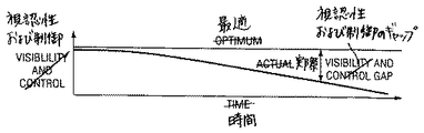
図1は、経時的な可視性および制御、ならびにシステムの高集積化の傾向を示す。アプリケーション開発者は、図1に示す最適可視性レベルを好む。この最適可視性レベルでは、関係するシステム・アクティビティ全ての可視性および制御が得られる。集積度の着実な進歩およびクロック・レートの上昇のために、時の経過と共に実際の可視性および制御の可用性が徐々に低下しつつある。これらの威力によって、可視性および制御のギャップ、最適な可視性および制御レベルと実際に使用可能なレベルとの間の差が生じる。時が経つに連れて、このギャップは広がっていく。アプリケーション開発メーカはギャップ生長レートを最小にすべく努力している。開発ツール・ソフトウエアおよび共に用いるハードウエア構成要素は、より少ないリソースで、しかも多種多様な方法で、より多くのことを行わなければならない。この使いやすさという課題に対する取り組みは、これらの影響力によって一層強化されている。 FIG. 1 shows the visibility and control over time, as well as the trend towards higher integration of the system. Application developers prefer the optimal visibility level shown in FIG. This optimal visibility level provides visibility and control of all relevant system activities. Due to steady progress in integration and increasing clock rates, the actual visibility and control availability is gradually decreasing over time. These forces create a gap in visibility and control, the difference between the optimal visibility and control level and the level actually available. Over time, this gap widens. Application developers strive to minimize gap growth rates. The development tool software and the hardware components used together have to do more with less resources and in a wide variety of ways. Efforts to address this ease of use issue are further enhanced by these influences.
今日の高集積度システム・オン・チップ(SOC:System-On-a-Chip)技術では、可視性および制御のギャップは、時間の経過と共に劇的に拡大しつつある。ロジック・アナライザや組み込み若しくは区分(partitioned)プロトタイプ・システムのような従来からのデバッグ選択肢は、今日のシステムの集積レベルや、増々高まりつつあるクロック・レートに歩調を合わせることはできない。集積度の上昇に伴って、多数のサブシステム構成要素を接続するシステム・バスがチップ上に移動するため、従来のロジック・アナライザはこれらのバスにアクセスできなくなる。バスの可視性の制約または事実上の喪失により、ロジック・アナライザのようなツールを用いても、開発中のシステムを制御するために必要なシステムのアクティビティを視認したり、トリガ機構を設けることができなくなった。この可視性の喪失に伴って、制御が不能となる。何故なら、アクセスできないものを制御することは困難であるからである。 In today's highly integrated system-on-a-chip (SOC) technology, the gap between visibility and control is dramatically expanding over time. Traditional debugging options, such as logic analyzers and embedded or partitioned prototype systems, cannot keep pace with the level of integration in today's systems and the ever-increasing clock rates. With the increase in integration, conventional logic analyzers cannot access these buses as system buses connecting a number of subsystem components move on the chip. Due to the limited or virtually lost visibility of the bus, tools such as logic analyzers can be used to view system activity and provide triggering mechanisms needed to control the system under development. I can no longer do it. With this loss of visibility, control is lost. This is because it is difficult to control what is not accessible.
この傾向に対処するために、システム設計者はこれらのバスを表出させるように努めた。このため、システム構成要素は、表出したバスを用いて試作システムの構成が可能となるように組み立てられた。この手法も、システム・クロック・レートの絶え間ない上昇歩調によって阻害される。中央演算装置(CPU)のクロック・レートが上昇すると、チップ間のインターフェースの速度はそれについて行けなくなる。チップ間通信レートの遅れを補償するためにインターフェース待機状態が追加されることにより、区分システムの性能は、その集積されている相手と歩調を合わすことができないことを、開発者は突き止めた。ある時点では、この性能低下は許容できないレベルにまで達し、区分プロトタイプ・システムはもはや実用的なデバッグ選択肢ではなくなった。現在では、生産機器は、アプリケーションの開発のためのプラットフォームとして機能しなければならない。 To address this trend, system designers have sought to expose these buses. For this reason, the system components were assembled so that a prototype system could be configured using the exposed bus. This approach is also hampered by the constant rise in the system clock rate. As the clock rate of the central processing unit (CPU) increases, the speed of the interface between the chips cannot keep up. The developer has determined that the performance of the partitioned system cannot keep pace with its integrated counterpart by adding an interface wait state to compensate for the inter-chip communication rate delay. At some point, this degradation has reached an unacceptable level, and the partitioned prototype system is no longer a viable debugging option. Currently, production equipment must function as a platform for application development.
また、CPUクロック・レートの上昇により、他の単純な可視性機構の可用性も制限される。CPUクロック・レートは最大I/O状態レートを上回ることができるので、ネーティブな形式で(native form)で情報をエクスポートする可視性ポートはもはやCPUについて行くことはできない。また、オンチップ・サブシステムも、CPUクロック・レートよりは遅いクロック・レートで動作する。この手法は、システムの設計を簡略化し、電力消費を削減するためには用いることができる。これらの開発は、単純な可視性ポートは、もはや、CPUアクティビティの正しい状態若しくは明確な表示(clear view)を送り出すためには、あてにできないことを意味する。可視性および制御性が低下するに連れて、アプリケーションを開発するために用いられる開発ツールの生産性が低下する。また、これらのツールは、可視性および制御性を維持するために必要なツールの複雑化のために、増々使用が困難になると思われる。システム・オン・チップによって生じた可視性、制御、および使いやすさの問題のために、製品開発サイクルが長引くことが多くなっている。 Also, increasing the CPU clock rate limits the availability of other simple visibility mechanisms. Since the CPU clock rate can exceed the maximum I / O state rate, a visibility port that exports information in native form can no longer follow the CPU. Also, the on-chip subsystem operates at a lower clock rate than the CPU clock rate. This approach can be used to simplify system design and reduce power consumption. These developments mean that a simple visibility port can no longer be relied upon to deliver the correct state or clear view of CPU activity. As visibility and control decrease, the productivity of development tools used to develop applications decreases. Also, these tools will become increasingly difficult to use due to the complexity of the tools needed to maintain visibility and control. Visibility, control, and ease-of-use issues created by system-on-a-chip are often prolonging product development cycles.
集積化の傾向が開発者には厳しいデバッグ環境を強いるとしても、これらは、問題をデバッグする新たな手法が出現するという希望も与える。高密度化やクロック・レートの上昇は、開発サイクル時間に対する重圧となるが、これらを解決する機会も生み出す。オンチップ・デバッグ機能は、これまで以上に手頃な価格となった。超大型メモリ構造が増々高速高性能チップ上で拡大するに連れて、CPUおよびメモリ・サブシステムに伴うランダム・ロジックに関係するシステム・コストは、システム・コスト全体の割合としては低下しつつある。数千個のゲートによるコスト上昇分は、これまでになく低くなっている。このサイズの回路は、場合によっては、今日のチップ設計の曲がり角に追いやられる場合もある。今日の高密度パッケージにおけるピン当たりのコスト上昇分も低下している。このため、より多くのピンをデバッグのために割り当てることが容易となった。手頃な価格のゲートおよびピンを共に用いることによって、システム・オン・チップによってもたらされた課題に取り組むために必要な、新たなオンチップ・エミュレーション機構(ファシリティ)の配備が可能となる。 Even if the integration trend forces developers to have a harsh debugging environment, they also give hope that new ways of debugging problems will emerge. Higher densities and higher clock rates put a strain on development cycle times, but also create opportunities to resolve them. On-chip debugging is now more affordable. As ultra-large memory structures expand on increasingly high-speed, high-performance chips, the system costs associated with random logic associated with CPUs and memory subsystems are decreasing as a percentage of overall system costs. The cost increase with thousands of gates is lower than ever. Circuits of this size are sometimes driven to the corners of today's chip designs. The cost per pin increase in today's high-density packages is also decreasing. This makes it easier to allocate more pins for debugging. The use of affordable gates and pins together allows for the deployment of new on-chip emulation facilities (facilities) needed to address the challenges posed by system-on-chip.
また、生産機器がアプリケーション・デバッグ・プラットフォームとしても機能する場合、これらは市場の目標に合わせて時間を捻出するのに十分なデバッグ機能(ケイパビリティ)を備えていなければならない。デバッグの必要性は個々のアプリケーションで異なるので、オンチップ・デバッグ機構を調節し、市場およびコストの要望に対して時間のバランスが取れるようにすることが望ましい。これらオンチップ機能はチップの循環コストに影響を及ぼすので、いずれの解決策にとっても規模変更可能性若しくはケスラビリティ(scalability)が最も重要である。「必要なものにだけ支払う」ことは、オンチップ・ツールの配備にとっても処理原則であるはずである。この新たな枠組みにおいて、システム構築者は、チップ・コストの制約や製品開発チームのデバッグについての要望のバランスを取りながら、オンチップ・デバッグ機構を、それ以外の機能性と共に指定することができる。 Also, if the production equipment also functions as an application debug platform, they must have enough debugging capabilities to allow time to meet market goals. Since the need for debugging varies from one application to another, it is desirable to adjust the on-chip debugging mechanism to balance time with market and cost needs. Since these on-chip functions affect the cyclical cost of the chip, scalability or scalability is of paramount importance for any solution. "Paying only what you need" should be a processing principle for the deployment of on-chip tools. In this new framework, system builders can specify an on-chip debug mechanism along with other functionality, while balancing chip cost constraints and product development team debugging needs.
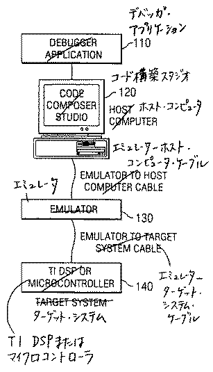
図2は、4つのエミュレータ構成要素を含むエミュレータ・システム100を示す。これら4つの構成要素は、デバッガ・アプリケーション・プログラム110、ホスト・コンピュータ120、エミュレーション・コントローラ130、およびオンチップ・デバッグ機構(ファシリティ)140である。図2は、これらの構成要素の接続を示す。ホスト・コンピュータ120は、ホスト120外部のエミュレーション・コントローラ130に接続されている。また、エミュレーション・コントローラ130はターゲット・システム140にも接続されている。ユーザは、デバッガ・アプリケーション・プログラム110を通じて、ターゲット・システム140上でターゲット・アプリケーションを制御することが好ましい。
FIG. 2 shows an emulator system 100 that includes four emulator components. These four components are a
ホスト・コンピュータ120は通常パーソナル・コンピュータである。ホスト・コンピュータ120は、エミュレータ・コントローラ130を通じてデバッグ機能にアクセスする。デバッガ・アプリケーション・プログラム110は、ホスト・コンピュータ120を通じて、ユーザに易しい形態でデバッグ機能を提供する。デバッグ・リソースは、必要に応じて、デバッグ・アプリケーション・プログラム110によって割り当てられ、このためのユーザの負担を軽減する。ソース・レベルのデバッグは、デバッグ・リソースを利用し、それらの複雑性をユーザには隠している。デバッガ・アプリケーション・プログラム110は、オンチップ・トレースおよびトリガ機構と共に、対象のチップ・アクティビティを選択し、記録し、表示する手段を設ける。トレース表示は、トレース・ログを生成したソース・コードと自動的に相関付けられる。エミュレータは、デバッグ制御およびトレース記録機能双方を備えている。
デバッグ機構は、JTAGまたは同様のシリアル・デバッグ・インターフェースを介した標準的なエミュレータ・デバッグ・アクセスを用いてプログラムすることが好ましい。ピンは貴重なので、本発明の好適な実施形態では、デバッグ・ピンの集合を、トレース、トリガ、およびその他のデバッグ機能で共有し、シリコン・コストにおける増加分を少なく済ませるようにした。固定したピン・フォーマットにも対応可能である。ピン共有選択肢を採用する(deploy)場合、デバッグ・ピンの利用は、各デバッグ・セッションの開始時に決定され、その後にターゲット・システム140にアプリケーション・プログラムを実行するように指令する。これによって、トレース・エクスポート帯域幅(trace export bandwidth)を最大化する。トレース帯域幅を最大化するには、最大数のピンをトレースに割り当てる。
The debug mechanism is preferably programmed using standard emulator debug access via a JTAG or similar serial debug interface. Because pins are valuable, the preferred embodiment of the present invention shares a set of debug pins with traces, triggers, and other debug functions to reduce the increase in silicon cost. A fixed pin format is also available. When deploying the pin sharing option, the use of debug pins is determined at the beginning of each debugging session and then directs the
システム内部のデバッグ機能および構築(ビルディング)ブロックは、可変とすることもできる。したがって、デバッガ・アプリケーション・プログラム100は、実行時(ランタイム)にコンフィギュレーションを確定する。この手法では、ハードウエア・ブロックが、コンフィギュレーションおよびレジスタ編成に関する一連の制約を満たす必要がある。他の構成要素は、システム・メモリ・マップにおいてブロックやその他のペリフェラル(peripheral)を突き止め位置づけるように設計されたハードウエア検索機能を設ける。デバッガ・アプリケーション・プログラム110は、検索機構を用いてリソースを突き止める。モジュールが位置するアドレスおよびタイプIDが、発見された各ブロックを一意に特定する。一旦IDが発見されたなら、設計データベースを用いれば、正確なコンフィギュレーションならびに全てのシステム入力および出力を確認することができる。
Debugging functions and building blocks inside the system can also be variable. Therefore, the debugger application program 100 determines the configuration at the time of execution (runtime). This approach requires that the hardware blocks meet a set of constraints on configuration and register organization. Other components provide a hardware search function designed to locate blocks and other peripherals in the system memory map. The
ホスト・コンピュータ120は、一般に、少なくとも64Mバイトのメモリを含み、Windows(登録商標)95、SR・2、Windows(登録商標) NT、またはそれ以降のバージョンのWindows(登録商標)を走らせることができる。ホスト・コンピュータ120は、エミュレータが必要とする通信インターフェースの1つに対応していなければならない。これらは、イーサネット(登録商標)10Tおよび100T、TCP/IPプロトコル、ユニバーサル・シリアル・バス(USB)、ファイアワイヤIEEE1394、ならびにSPP、EPPおよびECPのようなパラレル・ポートを含むことができる。
The
ホスト・コンピュータ120は、リアル・タイムのデータ交換帯域幅を決定するにあたって主要な役割を果たす。まず、ホスト・エミュレータ間通信は、最大維持リアル・タイム・データ交換帯域幅を規定する際に主要な役割を果たす。何故なら、エミュレータ・コントローラ130はその受信リアル・タイム・データ交換バッファが満杯になったら直ちにこれらを空にしなければならないからである。第2に、リアル・タイム・データの発信または受信を行うホスト・コンピュータ120は、受信したリアル・タイム・データ交換データの準備および送信または処理および格納を維持するための十分な処理能力またはディスク帯域幅を有していなければならない。技術的現状では、ファイアワイヤ(Firewire)通信チャネル(IEEE1394)を備えたパーソナル・コンピュータが、最大のリアル・タイム・データ交換帯域幅を得るには好ましい。この帯域幅は、他の通信選択肢よりも性能を10倍高めることができる。
エミュレーション・コントローラ130は、ホスト・コンピュータ120とターゲット・システム140との間にブリッジを設ける。エミュレーション・コントローラ130は、ホスト・コンピュータ120上で実行するデバッガ・アプリケーション・プログラム110とターゲット・システム140上で実行するターゲット・アプリケーションとの間で受け渡されるあらゆるデバッグ情報を処理する。現時点において好適な最小のエミュレータ・コンフィギュレーションは、リアル・タイム・エミュレーション、リアル・タイム・データ交換、トレース、および高度分析といった機能の全てに対応する。
The
エミュレーション・コントローラ130は、好ましくは、実行制御、メモリ、レジスタ・アクセスのようなリアル・タイム・エミュレーション機能に、3、4、または5ビットの走査型インターフェース(scan based interface)を通じてアクセスする。リアル・タイム・データ交換機能は、走査によって、または走査以外の直接的なターゲット・エミュレータ間接続を用いる3つの上位帯域幅リアル・タイム・データ交換フォーマットを用いることによってアクセスすることができる。入力および出力トリガによって、他のシステム構成要素がチップにデバッグ・イベントを知らせることや、その逆が可能となる。ビットI/Oによって、エミュレータはシステム入力および出力を刺激すること、または監視することが可能となる。ビットI/Oは、工場検査およびその他の時間的に厳しくない(non-time-critical)低帯域幅のエミュレータ/ターゲット動作に対応するために用いることができる。拡張動作モードは、デバイス検査およびエミュレーション動作モードを指定するために用いられる。エミュレータ・コントローラ130は、通信部およびエミュレーション部に区分される。通信部は、ホスト通信リンクを支援し、一方エミュレーション部はターゲットにインターフェースして、ターゲット・デバッグ機能およびデバイス・デバッグ・ポートを管理する。エミュレーション・コントローラ130は、先にこの中で概説した業界標準の通信リンクの1つを用いて、ホスト・コンピュータ120と交信する。ホスト・エミュレータ間接続は、汎用の配線技術を用いて行われる。ホスト・エミュレータ間の分離は、用いるインターフェースに適用される規格によって管理される。
エミュレーション・コントローラ130は、1本または複数のターゲット・ケーブルを通じてターゲット・システム140と交信する。デバッグ、トレース、トリガ、およびリアル・タイム・データ交換機能は、ターゲット・ケーブルを共有し、場合によっては、同じデバイス・ピンを共有する。ターゲット・システム140が、1本のケーブルには収容しきれないトレース幅を配備する場合、1本よりも多いターゲット・ケーブルが必要となる場合もある。トレース、リアル・タイム・データ交換、およびデバッグ通信は全て、このリンクを通じて行われる。エミュレータ・コントローラ130は、少なくとも2フィート(約60cm)のターゲット・エミュレータ間分離を設けることが好ましい。このエミュレーション技術は、50MHZまでの検査クロック・レート、および200から300MHZまたはこれ以上のトレース・クロック・レートが可能である。エミュレータの設計がターゲット・システム140の制約を緩和する技法を用いても、これらのレートでエミュレータ・コントローラ130およびターゲット・システム140間で通知を行うには、設計に努力が必要である。このエミュレーション技術は、チップのデバッグ・ピンの配置、基板のレイアウトに制約を賦課する場合があり、正確なピンのタイミングを必要とする。タイミングの制約を満たすのを補助するために、オンチップ・ピン・マクロを設ける。
オンチップ・デバッグ機能は、開発者に、豊富な開発機能を2段階の拡張可能な手法で提供する。第1段階では、CPUのメガ・モジュールに組み込んだリアル・タイム・エミュレーション機能を利用した機能性を備える。このリアル・タイム・エミュレーション機能は、一定の機能性を有し、永続的にCPUの一部であるが、殆どの場合、コアの外側に、高性能リアル・タイム・データ交換、高度分析およびトレース機能が追加される。これらの機能を個々に選択し、チップに加入する。エミュレーション・ペリフェラルをシステム設計に加入することにより、第2段階の機能性を形成する。コスト効率的なエミュレーション・ペリフェラルのライブラリは、システムを作成するための構築ブロックを含み、高度分析、高性能リアル・タイム・データ交換、およびトレース機能の構造化を可能にする。好適な実施形態では、5つの標準デバッグ・コンフィギュレーションが提供されるが、カスタム・コンフィギュレーションにも対応する。具体的なコンフィギュレーションについては、この中で後に扱う。 The on-chip debug function provides developers with a wealth of development features in a two-step, scalable way. The first stage has functionality utilizing a real-time emulation function built into the mega module of the CPU. This real-time emulation feature has certain functionality and is permanently part of the CPU, but in most cases, outside the core, high-performance real-time data exchange, advanced analysis and tracing Features are added. These functions are individually selected and added to the chip. Adding the emulation peripheral to the system design creates the second stage functionality. A library of cost-effective emulation peripherals contains the building blocks for creating the system, enabling advanced analysis, high-performance real-time data exchange, and structuring of trace functions. The preferred embodiment provides five standard debug configurations, but also supports custom configurations. The specific configuration will be dealt with later.
本発明は、2つの個別の比較器として動作可能なエミュレーション比較器であり、各々、プロセッサが発行するプロセッサ・メモリ・アクセス・アドレス(PMAA)およびプロセッサ・メモリ・アクセス・アドレス(PMAD)値をレジスタに格納されている基準値と比較する。あるいは、これは単一のデバイスとして動作することができ、メモリ・アクセス・アドレスを、二重境界範囲(double bounded range)を形成する2組の基準値と比較する。メモリ・アクセスのデータ内容は、アドレス比較に対する追加のクオリファイア(qualifier)として任意に用いることもできる。 The present invention is an emulation comparator operable as two separate comparators, each registering a processor memory access address (PMAA) and a processor memory access address (PMAD) value issued by a processor. Compare with the reference value stored in. Alternatively, it can operate as a single device, comparing memory access addresses to two sets of reference values forming a double bounded range. The data content of the memory access can optionally be used as an additional qualifier for the address comparison.
比較器の実施に必要な具体的なリソースは、所与の実施態様の要件および制約に依存して大きく変化する可能性がある。本願において記載する例では、範囲比較器は、2つの単一基準アドレス比較器と、対応するデータ比較器とを含み、2つのアドレスおよび2つのデータ比較論理機能に加えて、13のユーザ可視レジスタ(user-visible register)を必要とする。 The specific resources required to implement a comparator can vary widely depending on the requirements and constraints of a given implementation. In the example described herein, the range comparator includes two single reference address comparators and corresponding data comparators, plus two addresses and two data comparison logic functions, plus 13 user visible registers. (User-visible register).
2つの比較器の各々は、制御レジスタによって行われる選択に基づいて、独立した結果または依存した結果を得ることができる。2つのデータ比較器の結果は、関連するアドレス比較器に対するクオリファイアとして用いることができ、あるいは制御レジスタのコンフィギュレーションによっては無視することもできる。 Each of the two comparators can obtain independent or dependent results based on the selection made by the control register. The result of the two data comparators can be used as a qualifier for the associated address comparator, or can be ignored depending on the configuration of the control register.
プロセッサ・メモリ・アクセス・アドレスは、バイト、半ワード、ワード、二重(ダブル)ワードのように、プロセッサのアーキテクチャに応じて、多数のサイズとすることができる。ここに記載する実施態様における比較器は、基準を多数のサイズのメモリ・アクセスと比較することができる。 Processor memory access addresses can be of many sizes, depending on the processor architecture, such as bytes, half words, words, and double words. The comparator in the embodiment described herein can compare the reference with multiple sizes of memory accesses.
データ比較認定(qualification)を別として、比較器は、6つのアドレス比較判断基準の1つに基づいて一致を示すことができる。プロセッサ・メモリ・アクセス・アドレスは、基準と等しい場合、基準と等しくない場合、基準よりも大きい場合、基準以上の場合、基準未満の場合、または基準以下の場合があり得る。 Apart from the data comparison qualification, the comparator can indicate a match based on one of six address comparison criteria. The processor memory access address may be equal to, not equal to, greater than, greater than, less than, or less than the reference.
本発明は、完全一致または部分的一致の判断基準が可能である。これらは、均等一致(equality match)を求める場合には、2つのモードで具体化される。第1モードでは、プロセッサ・メモリ・アクセスが基準における全バイトと一致(オーバーラップ)した場合にのみ、一致が生ずる。第2モードでは、プロセッサ・メモリ・アクセスの少なくとも1バイトが基準と一致した場合に、一致が生ずる。 The present invention allows for a perfect match or partial match criterion. These are embodied in two modes when seeking an equality match. In the first mode, a match occurs only if the processor memory access matches (overlaps) all bytes in the reference. In the second mode, a match occurs if at least one byte of the processor memory access matches the criteria.
本願において説明する例で用いられるデータ比較器は、同一性均等比較器(identity equality comparator)である。データ比較器が一致を示すのは、重複判断基準によって認定された基準における対応するビットと一致するデータにおけるビットが全て等しい場合のみである。データ比較器は、基準マスク値を含む。この例の64ビット・メモリ・データ・バスの場合、2つの32ビット・レジスタが、2つのデータ比較器の各々に必要となる。マスクによって、一致に必要なデータ・ビットのカスタム化が可能になる。したがって、必ずしもビットの全てにおいて一致が必要な訳ではない。 The data comparator used in the example described in the present application is an identity equality comparator. The data comparator indicates a match only if all the bits in the data that match the corresponding bits in the criteria identified by the overlap criteria are equal. The data comparator includes a reference mask value. For the 64-bit memory data bus in this example, two 32-bit registers would be required for each of the two data comparators. The mask allows for customization of the data bits required for a match. Therefore, not all bits need to match.
比較器は、プロセッサのメモリ・マップへのインターフェースを通じてプログラムすることができる。本願では、このインターフェースをコンフィギュレーション・バス(cfgb)と呼ぶ。 The comparator can be programmed through an interface to the processor's memory map. In this application, this interface is called a configuration bus (cfgb).
比較器の機能は、ハードウエア・デバッグ・システムが用いるツールとして利用することができ、比較器の結果を入力として取り込み、デバッグ・システムのコンフィギュレーションに応じて、広い範囲の応答を与える。
本発明のこれらおよびその他の態様を図面に示す。
The functionality of the comparator can be used as a tool for a hardware debug system, taking the result of the comparator as input and providing a wide range of responses depending on the configuration of the debug system.
These and other aspects of the invention are illustrated in the drawings.
メモリ内の特定の位置に対するプロセッサのメモリ・アクセスを検出することができると、プロセッサ・コードの開発者がソフトウエアの問題を解決する(troubleshooting)する際に役立つので、これは必要である。本発明の比較器は、多数の特徴と高い柔軟性を有し、ソフトウエア・デバッグの作業を支援する強力なツールである。デバッグ処理には無関係な他の潜在的な用途には、プロセッサ動作の関連では、システム・イベントの相互作用または変化を開始させるために行う、プロセッサのメモリ・アクセスの検出を含むことができる。 This is necessary because the ability to detect a processor's memory access to a particular location in memory can help processor code developers troubleshoot software problems. The comparator of the present invention has many features and high flexibility, and is a powerful tool to support software debugging work. Other potential uses unrelated to the debugging process may include, in the context of processor operation, detecting the memory access of the processor to initiate an interaction or change of a system event.
本発明の比較器は、特定のメモリ・アドレスまたはアドレス範囲に対するプロセッサのメモリ・アクセスの有無を検出することができ、更にプロセッサのメモリ・アクセスに伴うデータによって、特定のメモリ・アドレスまたはアドレス範囲も認定することができる。ハードウエア・デバッグ・システムに比較器を一体化すると、プロセッサが実行するコードにおける問題を検出および解決するシステムの機能を高めることができる。 The comparator of the present invention can detect the presence or absence of a memory access of a processor to a specific memory address or an address range. Can be certified. Integrating the comparator with the hardware debug system can enhance the system's ability to detect and resolve problems in the code executed by the processor.
本発明の比較器は、デバッグ・プロセスがプロセッサのメモリ・アクセスの検出に基づく場合のソフトウエア問題の検出において、機能を強化し、柔軟性を高める。比較器において完全な重複または部分的重複の検出判断基準を使用可能であることは、あらゆるバイト境界におけるメモリ位置にアクセスを要求する可能性があるプロセッサ・アーキテクチャのために実施する場合には、特に重要である。この機能がないと、かかるアーキテクチャにおけるプロセッサのメモリ・アクセス・イベントの適正な検出には重大な制約が生じ、多くの場合不可能になることさえある。 The comparator of the present invention enhances functionality and increases flexibility in detecting software problems where the debug process is based on detecting processor memory accesses. The availability of full or partial duplicate detection criteria in the comparator is especially true when implemented for processor architectures that may require access to memory locations on any byte boundary. is important. Without this capability, the proper detection of processor memory access events in such architectures is severely limited and often even impossible.
図3は、ターゲット・システム140を用いたオンチップ・デバッグ・アーキテクチャの一例を示す。このアーキテクチャは、数個のモジュール・クラスを用いてデバッグ機能を構成する。これらのクラスの1つに、バス・イベント検出器210、補助イベント検出器211、およびカウンタ/ステートマシン213を含むイベント検出器がある。第2のクラスのモジュールは、トリガ・ビルダ(trigger builder)220を含むトリガ発生器である。第3のクラスのモジュールは、トレース収集230およびフォーマット化を含むデータ取得である。第4のクラスのモジュールは、トレース・エクスポート240、リアル・タイム・データ交換エクスポート241を含むデータ・エクスポートである。トレース・エクスポート240は、局部発振器245からのクロック信号によって制御される。局部発振器245については、後に詳しく説明する。最後のクラスのモジュールは、走査入力/出力をCPUコア201にインターフェースする走査アダプタ250である。最終的なデータのフォーマット化およびビンの選択は、ピン・マネージャおよびピン・マクロ260において行われる。
FIG. 3 shows an example of an on-chip debug architecture using the
システム・オン・チップ(system-on-chip)の個々の実施形態のいずれに対しても、デバッグ機能のサイズおよびそれに付随する処理能力は、完全な機能を削除するか、または配備するイベント検出器およびトリガ・ビルダの数を制限することによって調節することができる。加えて、トレース機能は、プログラム・カウンタ・トレースのみからプログラム・カウンタおよびデータならびにASICおよびCPU発生データのトレースまで徐々に増大させることができる。また、リアル・タイム・データ交換機能を任意に配備することもできる。オンチップ・ツールをカスタム化できるので、アプリケーション開発の枠組みを変化させることができる。過去においては、所与のCPUコアを用いたチップ設計は全て、固定した1組のデバッグ機能に限定されていた。現在では、チップの設計毎に最適化したデバッグ機能が得られる。この枠組みの変化によって、システム・アーキテクトには、製品開発リスクを管理するために必要なツールが手頃なコストで与えられることになった。尚、同じCPUコアであっても、異なるピン出力を有する異なるペリフェラルと共に用いることによって、異なるシステム・オン・チップ製品を具体化できることを注記しておく。これらの異なる実施形態は、異なるデバッグよびエミュレーション・リソースを必要とする場合もあり得る。本発明のモジュール性により、かかる実施形態の各々は、個々のシステム・オン・チップに応用するために必要なデバッグおよびエミュレーション・リソースのみを含むだけで済む。 For any particular embodiment of a system-on-chip, the size of the debug function and the attendant processing power may be reduced by an event detector that eliminates or deploys complete functionality. And by limiting the number of trigger builders. In addition, the trace function can be incrementally increased from a program counter trace only to a trace of the program counter and data and ASIC and CPU generated data. Further, a real-time data exchange function can be arbitrarily provided. The ability to customize on-chip tools can change the framework of application development. In the past, all chip designs with a given CPU core were limited to a fixed set of debug functions. At present, a debugging function optimized for each chip design can be obtained. This change in the framework has given system architects the tools they need to manage product development risks at a reasonable cost. Note that different system-on-chip products can be implemented using the same CPU core with different peripherals having different pin outputs. These different embodiments may require different debugging and emulation resources. Due to the modularity of the present invention, each such embodiment need only include the debug and emulation resources necessary for application to an individual system-on-chip.
リアル・タイム・エミュレーション・デバッグの基礎的な構成要素は、アプリケーションの開発に関係する基本的なデバッグおよび計測管理(instrumentation)に取り組むために用いられる。これは、あらゆる実行制御およびレジスタ可視性機能、ならびにブレークポイントやウオッチポイント機能のような最小のリアル・タイム・データ交換および分析機能を内蔵している。これらのデバッグ動作は、オンチップ・ハードウエア機構を用いて、アプリケーションの実行を制御し、レジスタやメモリへのアクセスを得る。リアル・タイム・エミュレーションが対応可能なデバッグ動作の一部は、ソフトウエア・ブレークポイントの設定、そのポイントにおける機械状態の観察、命令毎に正確な決定を観察するための1ステップ・コード前進、既知のメモリ位置への疑似書き込みの検出、およびメモリおよび周辺レジスタの視認および変更である。 The fundamental components of real-time emulation debugging are used to address basic debugging and instrumentation related to application development. It incorporates all execution control and register visibility functions, as well as minimal real-time data exchange and analysis functions such as breakpoints and watchpoint functions. These debugging operations use an on-chip hardware mechanism to control the execution of the application and gain access to registers and memory. Some of the debugging operations that can be supported by real-time emulation include setting a software breakpoint, observing the machine state at that point, stepping forward one step code to observe the exact decision for each instruction, known Detection of pseudo-writes to memory locations, and the viewing and modification of memory and peripheral registers.
リアル・タイム・エミュレーション機構は、CPUメガ・モジュール(CPU mega-module)内に組み込まれ、CPUコア201のファブリック(fabric)に編入される(weave)。これによって、CPUコア201を用いた設計が、デバッガ・アプリケーション・プログラム110のベースライン・デバッグ、測定管理、およびデータ転送機能に対応するだけの十分なデバッグ機構を有することに確証を与える。各CPUコア201は、基礎的な1組のエミュレーション機能を組み込んでいる。これらの機能には、実行(run)、1命令ステップ、休止および自由実行(halt and free run)のような実行制御、レジスタやメモリの表示および修正、ソフトウエアおよび最小限のハードウエア・プログラム・ブレークポイントを含むブレークポイント、ならびに最小限のハードウエア・データ・ブレークポイントを含むウオッチポイントを含むが、これらに限定されるのではない。
The real-time emulation mechanism is incorporated in a CPU mega-module, and is incorporated into a fabric of the CPU core 201 (weave). This confirms that the design using the
図4は、範囲比較器のアドレス構成要素を一体化した、2つの個別のアドレス比較器を含む比較器400を示す。比較器400は、バス・イベント検出器210の一部であることが好ましい。比較器400の柔軟な組み合わせにより、多種類のバス・イベント検出が可能となる。第1比較器は図4の上側にあり、第2比較器は下側にある。各アドレス比較器は、4つの主要構成要素、即ち、プロセッサ・メモリ・アクセス・サンプリング機構(マルチプレクサ411、412、421および422)、コンフィギュレーション・リソース(バス選択レジスタ402、比較器制御レジスタ403および405、アドレス基準レジスタ404および406)、プログラム・アクセス・アドレス大小比較器(メモリ・アドレス大小比較器413および423)、およびメモリ・アクセス比較制御ブロック(415および425)を有する。
FIG. 4 shows a
図4は、プロセッサ・メモリ・アクセス・サンプリング機構として機能する、4つのマルチプレクサ411、412、421および422を示す。図4は、2系統のプログラム・メモリ・アクセス・アドレス・バスを示す。マルチプレクサ411および421は、使用可能なデータ・アドレス・バスdmem_addr_0およびdmem_addr_1の中から所望のアドレス・バス信号を選択する。マルチプレクサ412および422は、選択したデータ・アドレス・バスに付随する、対応の制御バス信号mem_acc_ctl_0およびmem_acc_ctl_1を選択する。ユーザは、バス選択レジスタ402に書き込むことによって、2つの比較器に対するバス選択を制御する。
FIG. 4 shows four
図4は、比較器の構成の一部である5つのレジスタを示す。バス選択レジスタ402、比較器制御レジスタ403および405、ならびにアドレス基準レジスタ404および406は、コンフィギュレーション・バス・インターフェース(cfgb)と呼ぶメモリ・インターフェースを通じて、他のコンフィギュレーション変更可能なハードウエア・リソースと同様に、アクセスすることができる。このメモリ・インターフェースは、コンフィギュレーション制御信号(cfgb_ctl)を受け取るコンフィギュレーション・インターフェース制御部401を含む。コンフィギュレーショングレーション・データ(cfgb_data)およびコンフィギュレーション・クロック(cfgb_clk)が、バス選択レジスタ402、比較器制御レジスタ403、405、およびアドレス基準レジスタ404、406に供給される。レジスタ書き込み要求の受信およびcfbg_ctlを通じたレジスタの識別時に、コンフィギュレーション・インターフェース制御部401は、コンフィギュレーション・データ・バス上のデータを格納するレジスタを選択する。選択されたレジスタは、次のコンフィギュレーション・クロック信号の時点で、コンフィギュレーション・データ・バス上のデータを格納する。
FIG. 4 shows five registers which are part of the configuration of the comparator. The bus
バス選択レジスタ402に格納されたデータは、マルチプレクサ411、412、421および422を通じて、それぞれの基準値と比較される入力バスを規定する。マルチプレクサ411は、メモリ・アドレス大小比較器413およびメモリ・アドレス・バイト整合(alignment)マップ作成部(maker)(BAMM)414に供給するために、第1バスdmem_addr_0または第2バスdmem_addr_1のいずれかを選択する。マルチプレクサ412は、メモリ・アドレス大小比較器413およびメモリ・アドレス・バイト整合マップ作成部414に接続するために、第1制御バスmem_acc_ctl_0または第2制御バスmem_acc_ctl_1のいずれかを選択する。以下で説明するが、最終的な一致の判定は、それぞれの制御バス信号において示されるメモリ・アクセスのデータ・サイズに左右される可能性もある。マルチプレクサ411および412の選択は、port_select_0信号を通じてバス選択レジスタ402によって制御される。アドレス基準レジスタ404は、比較のために、基準アドレスをメモリ・アドレス大小比較器413およびメモリ・アドレス・バイト整合マップ作成部414に供給する。同様に、マルチプレクサ421および422は、port_select_1信号を通じたバス選択レジスタ402の制御の下で、アドレスおよび対応する制御バスを、メモリ・アドレス大小比較器423およびメモリ・アドレス・バイト整合マップ作成部424のために選択する。アドレス基準レジスタ406は、メモリ・アドレス大小比較器423およびメモリ・アドレス・バイト整合マップ作成部424のために基準アドレスを格納する。
The data stored in the bus
メモリ・アドレス大小比較器413および423は、基準値と選択したプロセッサ・メモリ・アクセス・アドレスとの間で実際の比較を行う。メモリ・アドレス大小比較器413および423は、各々、プロセッサ・メモリ・アクセス・アドレスが基準アドレスと等しい場合には同等信号(EQ)を発生し、プロセッサ・アクセス・アドレスが基準アドレスよりも大きい場合には超過信号(GT)を発生し、プロセッサ・アクセス・アドレスが基準アドレス未満の場合には未満信号(LT)を発生する。また、メモリ・アドレス大小比較器413および423は、それぞれのオフセット信号offset_0およびoffset_1も発生する。これらのオフセット信号は、対応するメモリ・アドレス・バイト整合マップ作成部414または424に供給される。メモリ・アドレス大小比較器413およびメモリ・アドレス・バイト整合マップ作成部414は、コンフィギュレーションおよび制御信号config_&_control_0を比較器制御レジスタ403から受け取る。メモリ・アドレス大小比較器423およびメモリ・アドレス・バイト整合マップ作成部424は、同様のコンフィギュレーションおよび制御信号config_&_control_1を比較器制御レジスタ405から受け取る。
The memory
オフセット信号offset_0およびoffset_1は、プロセッサ・メモリ・アクセス・アドレスと基準アドレスとの間のオフセットをバイト単位で記述する。それぞれのメモリ・アドレス・バイト整合マップ作成部414および424は、2つの信号を発生する。第1の信号を基準バイト整合マップ(ref_bam)と呼ぶ。第2の信号をメモリ・アクセス・バイト整合マップ(macc_bam)と呼ぶ。これらの信号は、基準アドレスとプログラム・メモリ・アクセス・アドレスとの間の完全な重複または部分的な重複を検出する際の基礎となる。
The offset signals offset_0 and offset_1 describe the offset between the processor memory access address and the reference address in bytes. Each memory address byte
メモリ・アドレス大小比較器413および423からの出力GT、LT、EQ、ならびにメモリ・アドレス・バイト整合マップ作成部414および424からの基準バイト整合マップ(ref_bam)およびメモリ・アクセス・バイト整合マップ(macc_bam)は、各メモリ・アクセス比較制御ブロック415および425に供給される。メモリ・アドレス・バイト整合マップ作成部414および424からのメモリ・アドレス・バイト整合マップ信号およびメモリ・アクセス・バイト整合マップは、各メモリ・アクセス比較制御ブロック415および425に供給される。メモリ・アクセス比較制御ブロック415および425は、これらの入力信号、各ORゲート416および426からの比較器認定(クオリフィケーション)、ならびに比較器制御レジスタ403および405において定義されるコンフィギュレーション情報に応じて、対応するmem_access_event出力を発生する。メモリ・アクセス比較制御ブロック415および425は、対応するメモリ・アドレス大小比較器413および423からの3つの結果信号(GT,LT,EQ)を取り込み、これらを6つの比較モード選択に拡張する。これらは、超過、未満、同等、不等、以下、および以上である。同時に、対応する比較器制御レジスタ403および405からのコンフィギュレーション信号に基づいてバイト整合マップ信号ref_bamおよびmacc_bamを比較し、重複一致結果を生成する。2つの比較器の各々は、6つの比較モデルの内の1つにプログラムすることができ、当該モデルの検出判断基準および重複一致結果を用いて、部分的比較器検出イベント(partial comparator detection event)を生成する。メモリ・アクセス比較制御ブロック415は、local_event_0信号をメモリ・アクセス比較制御ブロック425に供給する。メモリ・アクセス比較制御ブロック425は、local_event_1信号をメモリ・アクセス比較制御ブロック415に供給する。
The outputs GT, LT, and EQ from the memory
各メモリ・アクセス比較制御ブロック415および425は、それぞれの信号look_up_table_0およびlook_up_table_1を通じて、対応する比較器制御レジスタ403および405から4エントリの参照テーブルを受け取る。テーブル参照信号によって、最終出力mem_access_event_0およびmem_access_event_1が、他のメモリ・アクセス比較制御ブロックからのlocal_event信号に依存することが可能となる。この依存性により、各比較器が一方の限度値を検査することによって、アドレス範囲の比較が可能となる。中央演算装置のストール信号(cpu_stall)がアクティブのとき、それぞれの比較器制御レジスタ403および405に格納されているコンフィギュレーション・データに応じて、メモリ・アクセス比較制御ブロック415および425のいずれかまたは双方を非動作、ディスェーブルすることができる。
Each memory access
メモリ・アクセスが正確に基準アドレスに等しくないことにユーザが関心を示す可能性はいくつかある。基準アドレスおよびバス・アドレスのそれぞれのデータ・サイズによっては、異なるアドレスを有するバス・アクセスは基準アドレスに触れる場合がある。例えば、データ・バイトの正確なアドレスを有していないと、ワードまたは半ワードの書き込みが、1バイトのデータを上書きしてしまう場合がある。通常、ユーザは、追跡しているメモリ・アクセスが基準に触れるか否かについてのみ関心があり、正確なデータ・サイズやバス・アドレスの組み合わせには関心がない。比較動作が正しく行われたか否か判定する規則は、単に、「対象とするバイトのいずれにも触れた場合、比較は正しく行われた」というように、単に述べることができる。このような一致は、アドレス・バス値およびデータ・サイズ双方に依存する。 There are several possibilities for the user to show that the memory access is not exactly equal to the reference address. Depending on the data size of each of the reference address and the bus address, a bus access having a different address may touch the reference address. For example, without the correct address of the data byte, a word or half-word write may overwrite one byte of data. Typically, the user is only concerned with whether the memory access being tracked meets the criteria, not the exact data size or bus address combination. The rules for determining whether the comparison operation was successful may simply be stated as "if any of the bytes of interest were touched, the comparison was successful". Such a match depends on both the address bus value and the data size.
基準アドレスは、32ビット・アドレス境界に整合された一連のバイトと見なされ、基準アドレスのバイト・アドレスおよび基準アドレスに関与するサイズに基づいて配置される。基準アドレスに関与するサイズは、1バイト(バイト)、2バイト(半ワード)、または4バイト(全ワード)とすることができる。バス・アドレスは、同じように表される。比較器の一致が宣告されるのは、以下の条件のいずれもが真と評価されたときである。同等比較をイネーブルしたときに、バス・アドレスが基準アドレスのいずれのバイトを参照することによっても、同等一致が生じる。超過比較を指定したときに、基準アドレスが指定する最上位バイトよりも高いアドレスを有するいずれかのバイトを、バス・アドレスが参照することによって、超過一致が生じる。未満比較を指定したときに、基準アドレスが指定する最下位バイトよりも低いアドレスを有するいずれかのバイトを、バス・アドレスが参照することによって、未満一致が生じる。尚、これら3つの条件は同時に一致を生じ得ることを注記しておく。例えば、完全な1ワードのメモリ・アクセスが、1バイトとして指定された基準アドレスと重複する場合、この条件が生じる。これによって、いずれのサイズのアクセスであっても、指定した1組のバイトの上位、下位、またはその上に触れれば、一致を宣告することができる。 The reference address is considered as a series of bytes aligned on a 32-bit address boundary and is arranged based on the byte address of the reference address and the size involved in the reference address. The size involved in the reference address can be 1 byte (byte), 2 bytes (half word), or 4 bytes (all words). Bus addresses are similarly represented. A comparator match is declared when any of the following conditions evaluates to true: When equality comparison is enabled, an equality match occurs when the bus address references any byte of the reference address. When an overcomparison is specified, an overmatch occurs when the bus address references any byte having an address higher than the most significant byte specified by the reference address. When specifying a less-than comparison, a less-than match occurs when the bus address references any byte having an address lower than the least significant byte specified by the reference address. Note that these three conditions can result in a match at the same time. For example, this condition occurs when a complete one-word memory access overlaps with a reference address specified as one byte. As a result, regardless of the access size, a match can be declared by touching the upper, lower, or upper part of a specified set of bytes.
表1は、いずれのバイト・アドレス可能な境界にて開始する全(フル)ワード、半ワードおよびバイト・アクセスに対応するメモリ・システムについて、非整合バス比較の事例を5つ示すものである。表1の中央にある3つの事例は、基準アドレスおよびバス・アドレスのサイズを条件とする。他の2つの事例は、アドレス・サイズの情報がなくとも、完全な比較を可能とする。
アクセスは、バス・アドレス[1:0]およびサイズ[1:0]データから作成した、1連の7つのバイト・イネーブルに分割される。これら7つのバイト・イネーブルによって、32ビット・ワードに対応するバイト・アドレスのいずれから開始する全ワード・アクセスでも指定し、このアクセスによる作用を受けるバイトの位置を規定することができる。メモリ・アクセス比較制御ブロック415および425は、それぞれのメモリ・アドレス大小比較器413および423からのGT、LT、EQ出力と、それぞれのメモリ・アドレス・バイト整合マップ作成部414および424からの基準バイト整合マップ(ref_bam)およびメモリ・アクセス・バイト整合マップ(macc_bam)とを受け取り、それぞれのバス及び基準データ・サイズに基づいて、要求されたアドレス比較を形成する。
Access is divided into a series of seven byte enables created from bus address [1: 0] and size [1: 0] data. These seven byte enables allow specifying a full word access starting from any of the byte addresses corresponding to the 32-bit word and defining the location of the byte affected by the access. The memory access comparison control blocks 415 and 425 include GT, LT, and EQ outputs from the respective memory
表2は、比較器制御レジスタ403に格納されている認定(クオリフィケーション)信号config_&_control_0およびlook_up_table_0のコード化の一例を示す。比較器制御レジスタ413に格納されているconfig_&_control_1およびlook_up_table_1も同様にコード化する。
EXACTビット(ビット11)は、アドレス比較の正確度を規定する。EXACT=0の場合、いずれのバイトが基準アドレスに触れても、一致が生ずる。EXACT=1の場合、正確なアドレス一致の場合にのみ、一致が生ずる。 The EXACT bit (bit 11) defines the accuracy of the address comparison. If EXACT = 0, a match occurs regardless of which byte touches the reference address. If EXACT = 1, a match occurs only if there is an exact address match.
REFビット(ビット10および9)は、アドレスおよびデータ基準値のサイズを定義する。これを表3に示す。
EXEビット(ビット8)は、認定プログラム・カウンタ・イベントを定義する。EXE=1の場合、ディスパッチ・ユニット(dispatch unit)からの1つの命令の実行を伴うプログラム・カウンタ・バス・イベント全ての認定が許可される。EXE=0の場合、1つの命令発行を伴うプログラム・カウンタ・バス・イベントの認定はマスクされる。このマスキングによって、アドレスのみに基づいた単純な関数範囲(function range)を許可する(STALLをセットしている限り)。これは、プログラム・カウンタ・アドレス範囲にのみ有用である。 The EXE bit (bit 8) defines a qualified program counter event. If EXE = 1, certification of all program counter bus events involving execution of one instruction from the dispatch unit is allowed. If EXE = 0, the qualification of the program counter bus event with one instruction issue is masked. This masking allows a simple function range based on addresses only (as long as you set STALL). This is only useful for the program counter address range.
STALLビット(ビット7)は、ストールがバス・イベントとして認定可能か否か制御する。STALL=1の場合、アクティブなパイプライン・サイクルを伴うバス・イベントの認定はマスクされる。これによって、EXEビットが0である限り、ブロック範囲イベントをレベルとして許可する。これは、プログラム・カウンタ・アドレス範囲にのみ有用である。STALL=0の場合、データ・アクセスおよびプログラム・カウンタ・アクセスにおけるストールを許可して、バス・イベントを認定する。 The STALL bit (bit 7) controls whether the stall can be qualified as a bus event. If STALL = 1, qualification of bus events with active pipeline cycles is masked. This allows the block range event as a level as long as the EXE bit is 0. This is only useful for the program counter address range. When STALL = 0, stalls in data access and program counter access are permitted, and bus events are recognized.
ETYPEビット(ビット6)は、エミュレーション・メモリ・アドレスの検出を制御する。ETYPE=0の場合、エミュレーション・アクセス・サイクルは検出されない。
R/Wビット(ビット4)は、読み出し動作または書き込み動作について、一致が生じたか否か判定を行う。R/W=1の場合、比較器は読み出し動作について検出を行う。R/W=0の場合、比較器は書き込み動作について検出を行う。
QLUフィールド(ビット3:0)は、データ・サイズに必要なバス・イベントの認定を定義する。表4は、これらのビットのコード化を示す。
The R / W bit (bit 4) determines whether a match has occurred for a read operation or a write operation. When R / W = 1, the comparator detects a read operation. If R / W = 0, the comparator detects a write operation.
The QLU field (bits 3: 0) defines the bus event qualification required for data size. Table 4 shows the encoding of these bits.
これらのビットは、バス検出ハードウエアに対して対象となるアクセス・サイズまたは複数のアクセス・サイズを判定する。参照テーブルは、1組のビットを、検出したアクセス・サイズにマップする。 These bits determine the target access size or sizes for the bus detection hardware. The lookup table maps a set of bits to the detected access size.
図5は、随伴するコンパニオン・データ比較器(companion data comparator)を示す。好適な実施形態では、2つのデータ比較器500を用い、それぞれのORゲート416および426を介して、各メモリ・アクセス比較制御ブロック415および425に1つずつ接続されている。実施態様の多くでは、1つのみのデータ比較器500を用いて、両アドレス比較器で共有することも容認できる。こうすると、いくらか柔軟性が低下するという欠点がある。
FIG. 5 shows an associated companion data comparator. In the preferred embodiment, two
データ比較器500の好適な実施形態は、64ビット・データ・バス上で動作し、したがって32ビット・データ・バスの実施態様に要するよりも、2倍のリソースがデータ経路において必要となる。データ比較器500は、6つの論理セクションを含む。即ち、コンフィギュレーション・リソース(401、402、403、404、505、506および507)、サンプリング・ロジック(510、511、512、513、514)、メモリ・データ同一性比較器(521および522)、メモリ・アクセス・データ・バイト・アドレス範囲重複比較器(530)、およびメモリ・アクセス・データ比較制御部(540)である。
The preferred embodiment of
コンフィギュレーション・リソースは、コンフィギュレーション・インターフェース制御部410および7つのレジスタを含む。バス選択レジスタ402およびインターフェース制御部401は、図4に示したアドレス比較器400と共有される。比較器制御レジスタ403およびアドレス基準レジスタ404は、対応するアドレス比較機能と共有される。64ビットの比較データは、2つの32ビット・ワードとして格納される。下位データ基準レジスタ(data_reference_reg_l)505は、最下位(least significant)32ビットを格納し、上位データ基準レジスタ(data_reference_reg_h)507は、最上位(most significant)32ビットを格納する。64ビットのマスク・データは、2つの32ビット・ワードとして格納される。下位マスク・レジスタ(mask_reg_l)506は、最下位32ビットを格納し、上位マスク・レジスタ(mask_reg_h)508は、最上位32ビットを格納する。マスク・レジスタ506および508におけるビット位置が0にセットされていると、一致と見なされ、1にセットされていると、比較が行われる。これらのレジスタには、プロセッサ内にある他のコンフィギュレーション変更可能なハードウエア・リソースと同様に、コンフィギュレーション・バスおよびコンフィギュレーション・インターフェース制御部401を通じてアクセスすることができる。
The configuration resources include a configuration interface controller 410 and seven registers. The
サンプリング・ロジックは、メモリ・アクセスに関するデータ・バスおよび関連する制御およびアドレスの情報選択を定義する。マルチプレクサ511は、下位メモリ・データ・バイト同一性比較器521への供給のために、最下位32ビット・データ・バスmem_data_low_0またはmem_data_low_0のいずれかを選択する。マルチプレクサ512は、メモリ・データ・バイト同一性比較器522への供給のために、最上位32ビット・データ・バスmem_data_high_0またはmem_data_high_0のいずれかを選択する。選択は、バス選択レジスタ402からのport_select信号、ならびにそれぞれのデータ・バスに対応するメモリ・アクセス制御信号mem_acc_ctl_0およびmem_acc_ctl_1に応答して、データ・マルチプレクサおよび経路制御ロジック510によって制御される。ユーザは、バス選択レジスタ402に書き込むことによって、比較に用いるためのバス選択を制御する。
Sampling logic defines the data bus and associated control and address information selection for memory accesses.
下位メモリ・データ・バイト同一性比較器521は、下位データ基準レジスタ505からの基準データの最下位32ビット、下位マスク・レジスタ506からのマスク・データの最下位32ビット、およびマルチプレクサ511からのメモリ・データの選択された最下位32ビットを受け取る。同様に、上位メモリ・データ・バイト同一性比較器522は、上位基準レジスタ507からの基準データの最上位32ビット、上位マスク・レジスタ508からの最上位マスク・データの32ビット、およびマルチプレクサ512からのメモリ・データの選択された最上位32ビットを受け取る。メモリ・データ・バイト同一性比較器521および522は、対応する一致信号byte_data_match_0およびbyte_data_match_1を発生する。メモリ・データ・バイト同一性比較器521および522は、各々、対応するマスクを用いて、データ・バスの個々のバイト各々に対して同一性比較を行う。各バス一致信号は、対応する4バイトについて別個に一致を示す。これによって、多数のサイズに対する同時動作が可能となる。最小データ・サイズが1バイトであり、他のサイズが全てバイトの倍数であると仮定すると、データ比較器は、バイト(8ビット)、半ワード(16ビット)、ワード(32ビット)、およびダブルワード(64ビット)という4つのデータ・サイズのいずれについても、一致の指示を与えることができる。
The lower memory data
メモリ・アクセス・データ・バイト・アドレス範囲重複検出器530は、メモリ・アクセスのバイトと基準のバイトとの間の相対的な重複に関する情報address_byte_overlapを発生する。マルチプレクサ513は、データ・マルチプレクサおよび経路制御ロジック510からのport_select信号の制御の下で、一方のメモリ・アクセス制御信号mem_acc_ctl_0またはmem_acc_ctl_1を選択する。同様に、マルチプレクサ514は、ポート選択信号の制御の下で、アドレス・バスdmem_addr_0およびdmem_addr_1の一方を選択する。メモリ・アクセス・データ・バイト・アドレス範囲重複検出器530は、マルチプレクサ513からの選択されたメモリ・バス制御信号、マルチプレクサ514からの選択されたアドレス・バス信号、アドレス基準レジスタ404からのアドレス、および比較器制御レジスタ403からのコンフィギュレーションおよび制御信号を受け取る。メモリ・アクセス・データ・バイト・アドレス範囲重複検出器530は、アドレス比較器400において用いられる重複計算と同様に、8つの重複信号(address_byte_overlap)を生成し、バイト整合マップを作成する。
The memory access data byte address
メモリ・アクセス・データ比較制御部540は、data_compare_result_0を発生する。メモリ・アクセス・データ比較制御部540は、8つの部分的データ比較結果、4つがメモリ・データ・バイト同一性比較器521からのbyte_data_match_1、そして4つがメモリ・データ・バイト同一性比較器522からのbyte_data_match_hと、メモリ・アクセス・データ・バイト・アドレス範囲重複検出器530から8つのaddress_byte_overlap信号と、メモリ・アクセスからの制御バス情報(mem_acc_ctl_0およびmem_acc_ctl_1)と、比較器制御レジスタ403からの参照テーブル(look up table)・データとを受け取る。メモリ・アクセス・データ比較制御部540は、これらの信号を用いて、データ一致信号(data_compare_result_0)を発生する。前述のように、このデータ一致信号は、アドレス比較を認定するために用いることができる。
The memory access data
表5は、ダブルワード未満の基準データ・サイズについて、値の複製方法を示す。
列B0からB7は、下位データ基準レジスタ505および上位データ基準レジスタ507における8バイトに対応する。下位バイトB0・B3は、下位データ基準レジスタ505に格納され、上位バイトB4・B7は上位データ基準レジスタ507に格納される。このようなデータの複製を、適切なデータ・ストローブと共に行うことによって、メモリ・アクセス・サイズおよび基準サイズのいずれの組み合わせについても、いかなる所望の一致でも可能となる。データ比較には、アクセスによるデータ・バイト基準のみが含まれる。
Columns B0 to B7 correspond to 8 bytes in lower
本発明の好適な実施形態は、2つのデータ比較器500を含む。第1のデータ比較器を図5に示す。第2のアドレス比較器は、比較器制御レジスタ403が比較器制御レジスタ405と置き換えられ、アドレス基準レジスタ404がアドレス基準レジスタ406と置き換えられ、比較出力data_compare_result_1が、ORゲート416ではなく、ORゲート426に供給されることを除いて同様である。更に別の代替物として、図5に示すような2つのデータ比較器を共に用いて、データ範囲の比較を行うこともできる。一方のデータ比較器はデータ範囲の下側の境界を検出し、第2のデータ比較器はデータ範囲の上側の境界を検出する。このデータ範囲比較の結果は、データ比較器認定信号を通じて、データ比較認定ORゲート416および426の選択された一方または双方に供給することができる。
The preferred embodiment of the present invention includes two
以上の説明に関して更に以下の項目を開示する。
(1) メモリ・アクセス・アドレス比較器であって、
第1基準アドレスを格納する第1プログラマブル基準アドレス・レジスタと、
前記第1基準アドレスおよび第1アドレス入力を受け取り、前記第1基準アドレスと前記アドレス入力との間の整合を示す少なくとも1つの第1整合信号を発生する第1アドレス整合マップ作成部と、
前記第1プログラマブル基準アドレス・レジスタからの前記第1基準アドレスと前記第1アドレス入力とを受け取り、前記第1基準アドレスと前記アドレス入力上のアドレスとの関係に応じて、超過出力、未満出力または同等出力を発生する第1比較器と、
第2基準アドレスを格納する第2プログラマブル基準アドレス・レジスタと、
前記第2基準アドレスおよび第2アドレス入力を受け取り、前記第2基準アドレスと前記アドレス入力との間のオフセットを示す少なくとも1つの第2オフセット信号を発生する第2アドレス整合マップ作成部と、
前記第2プログラマブル基準アドレス・レジスタからの前記第2基準アドレスと前記アドレス入力とを受け取り、前記第2基準アドレスと前記アドレス入力上のアドレスとの間の関係に応じて、超過出力、未満出力または同等出力を発生する第2比較器と、
第1および第2アドレス整合マップ作成部のそれぞれならびに第1および第2比較器のそれぞれに接続された第1および第2メモリ・アクセス制御ユニットであって、各々、前記少なくとも1つの整合信号、前記対応する比較器の前記超過出力、前記未満出力および前記同等出力の少なくとも1つに応じて、対応する第1および第2ローカル・イベント信号を選択的に発生し、更に、前記他方のメモリ・アクセス制御ユニットの前記ローカル信号に応じて対応する第1および第2メモリ・アクセス・イベント信号を選択的に発生する、第1および第2メモリ・アクセス制御ユニットと、
を備え、
前記第1メモリ・アクセス制御ユニットが、前記少なくとも1つの第1整合信号を受け取った場合、前記第1ローカル・イベント信号および前記第1メモリ・アクセス・イベント信号が、前記第1基準アドレスおよび前記アドレス入力間における完全な重複または部分的重複に選択的に応じ、
前記第2メモリ・アクセス制御ユニットが、前記少なくとも1つの第2整合信号を受け取った場合、前記第2ローカル・イベント信号および前記第2メモリ・アクセス・イベント信号が、前記第2基準アドレスおよび前記アドレス入力間における完全な重複または部分的重複に選択的に応ずる、メモリ・アクセス・アドレス比較器。
(2) 更に、
第1データ・アクセス・アドレス・バスと、
第2データ・アクセス・アドレス・バスと、
前記第1データ・アクセス・アドレス・バスを受ける第1入力と、前記第2データ・アクセス・アドレス・バスを受ける第2入力と、制御入力と、前記第1アドレス整合マップ作成部および前記第1比較器のアドレス入力に接続された出力とを有する第1マルチプレクサと、
前記第1データ・アクセス・アドレス・バスを受ける第1入力と、前記第2データ・アクセス・アドレス・バスを受ける第2入力と、制御入力と、前記第2アドレス整合マップ作成部および前記第2比較器のアドレス入力に接続された出力とを有する第2マルチプレクサと、
前記第1および第2マルチプレクサの前記制御入力に接続されたプログラマブル・バス選択レジスタであって、前記第1および第2マルチプレクサを独立して制御し、前記第1および第2比較器の前記アドレス入力への供給のために、前記第1データ・アクセス・アドレス・バスまたは前記第2データ・アクセス・アドレス・バスのいずれかを選択する、プログラマブル・バス選択レジスタとを備えている第1項記載のメモリ・アクセス・アドレス比較器。
(3) 更に、
前記第1メモリ・アクセス制御ユニットに接続され、前記第1メモリ・アクセス制御ユニットを制御して、前記アドレス入力が、前記第1基準アドレスに対して(1)超過、(2)未満、(3)同等、(4)不等、(5)以下、および(6)以上から選択された1つである場合、前記第1ローカル信号を発生し、前記第1メモリ・アクセス・イベント信号が前記第2ローカル信号に依存するか、またはこれとは無関係とするか選択する、第1プログラマブル比較制御レジスタと、
前記第2メモリ・アクセス制御ユニットに接続され、前記第2メモリ・アクセス制御ユニットを制御して、前記アドレス信号が、前記第2基準アドレスに対して(1)超過、(2)未満、(3)同等、(4)不等、(5)以下、および(6)以上から選択された1つである場合、前記第2ローカル信号を発生し、前記第2メモリ・アクセス・イベント信号が前記第1ローカル信号に依存するか、またはこれとは無関係とするか選択する、第2プログラマブル比較制御レジスタとを備えている第1項記載のメモリ・アクセス・アドレス比較器。
(4) 更に、
前記第1メモリ・アクセス制御ユニットに接続され、前記第1メモリ・アクセス制御ユニットを制御して、前記アドレス入力が、前記第1基準アドレスおよび前記第1アドレス入力間の完全な重複または部分的な重複から選択した一方である場合、前記第1ローカル信号を発生する、第1プログラマブル比較制御レジスタと、
前記第2メモリ・アクセス制御ユニットに接続され、前記第2メモリ・アクセス制御ユニットを制御して、前記アドレス入力が、前記第2基準アドレスおよび前記第2アドレス入力間の完全な重複または部分的な重複から選択した一方である場合、前記第2ローカル信号を発生する、第2プログラマブル比較制御レジスタとを備えている第1項記載のメモリ・アクセス・アドレス比較器。
(5) 前記第1アドレス入力が、前記第1アドレスにおけるメモリ・アクセスに対応するデータ・サイズの指示を含み、
更に、前記第1メモリ・アクセス制御ユニットに接続され、前記第1基準アドレスに対応するデータ・サイズを指定する第1プログラマブル比較制御レジスタを備え、前記第1基準アドレスおよび前記第1アドレス入力のそれぞれのデータ・サイズに応じて、前記アドレス入力が前記第1基準アドレスおよび前記第1アドレス入力間の完全な重複または部分的重複から選択した1つである場合に、前記第1メモリ・アクセス制御ユニットが前記第1ローカル信号を発生し、
前記第2アドレス入力が、前記第2アドレスにおけるメモリ・アクセスに対応するデータ・サイズの指示を含み、
更に、前記第2メモリ・アクセス制御ユニットに接続され、前記第1基準アドレスに対応するデータ・サイズを指定する第2プログラマブル比較制御レジスタを備え、前記第2基準アドレスおよび前記第2アドレス入力のそれぞれのデータ・サイズに応じて、前記アドレス入力が前記第2基準アドレスおよび前記第2アドレス入力間の完全な重複または部分的重複から選択した1つである場合に、前記第2メモリ・アクセス制御ユニットが前記第2ローカル信号を発生する、第1項記載のメモリ・アクセス・アドレス比較器。
(6) 更に、
少なくとも1つのデータ比較器であって、各々、メモリ・アクセスのデータが対応するデータ基準と一致するか否かを示す、対応するデータ一致信号を発生する、データ比較器を備えており、
前記第1メモリ・アクセス制御ユニットが、前記少なくとも1つのデータ比較器から前記一致信号を受け取った場合、前記第1ローカル・イベント信号および前記第1メモリ・アクセス・イベント信号が、前記対応するデータ一致信号に選択的に依存し、
前記第2メモリ・アクセス制御ユニットが、前記少なくとも1つのデータ比較器から前記一致信号を受け取った場合、前記第2ローカル・イベント信号および前記第2メモリ・アクセス・イベント信号が、対応するデータ一致信号に選択的に依存する、第1項記載のメモリ・アクセス・アドレス比較器。
(7) 更に、
前記第1メモリ・アクセス制御ユニットに接続され、前記第1メモリ・アクセス制御ユニットを制御して、前記第1アドレス入力が、前記第1基準アドレスおよび前記第1アドレス入力間の完全な重複または部分的な重複から選択した一方である場合、前記第1ローカル信号を発生する、第1プログラマブル比較制御レジスタと、
前記第2メモリ・アクセス制御ユニットに接続され、前記第2メモリ・アクセス制御ユニットを制御して、前記アドレス入力が、前記第2基準アドレスおよび前記第2アドレス入力間の完全な重複または部分的な重複から選択した一方である場合、前記第2ローカル信号を発生する、第2プログラマブル比較制御レジスタとを備えている、第6項記載のメモリ・アクセス・アドレス比較器。
(8) 前記少なくとも1つのデータ比較器は、単一のデータ一致信号を発生する単一のデータ比較器から成り、前記第1および第2メモリ・アクセス制御ユニットが前記単一のデータ比較器から前記単一のデータ一致信号を受け取る、第6項記載のメモリ・アクセス・アドレス比較器。
(9) 前記少なくとも1つのデータ比較器は、
第1データ一致信号を発生する第1データ比較器であって、前記第1メモリ・アクセス制御ユニットが前記第1データ一致信号を受け取る、第1データ比較器と、
第2データ一致信号を発生する第2データ比較器であって、前記第2メモリ・アクセス制御ユニットが前記第2データ一致信号を受け取る、第2比較器と、
から成る、第6項記載のメモリ・アクセス・アドレス比較器。
(10) 前記少なくとも1つのデータ比較器は、
前記データ基準を格納するプログラマブル・データ基準レジスタと、
前記プログラマブル・データ基準レジスタ内に格納されている前記データ基準のそれぞれの区間と、データ・バス上のデータとを比較し、それぞれの区間の一致を示す区間一致信号を発生する、データ比較器と、
前記区間一致信号を受け取り、該区間一致信号に応じて選択的にデータ比較信号を発生するメモリ・アクセス・データ比較制御ユニットと、
を含む、第9項記載のメモリ・アクセス・アドレス比較器。
(11) 前記少なくとも1つのデータ比較器は、更に、
前記メモリ・アクセス・データ比較制御ユニットに接続され、前記メモリ・アクセス・データ比較制御ユニットを制御して、前記アドレス入力が、全区間の一致または選択した区間の一致から選択した一方である場合、前記データ比較信号を発生するプログラマブル比較制御レジスタを含む、第10項記載のメモリ・アクセス比較器。
(12) 更に、
第1データ・バスと、
第2データ・バスと、
前記第1データ・バスを受ける第1入力と、前記第2データ・バスを受ける第2入力と、制御入力と、前記データ比較器に接続された出力とを有するマルチプレクサと、
前記第1マルチプレクサの制御入力に接続されたプログラマブル・バス選択レジスタであって、前記マルチプレクサを制御して、前記データ比較器の前記アドレス入力に供給するために、前記第1データ・バスまたは前記第2データ・バスのいずれかを選択する、プログラマブル・バス選択レジスタと、
を備えている第9項記載のメモリ・アクセス・アドレス比較器。
The following items are further disclosed with respect to the above description.
(1) a memory access address comparator,
A first programmable reference address register for storing a first reference address;
A first address match map creator that receives the first reference address and the first address input and generates at least one first match signal indicating a match between the first reference address and the address input;
Receiving the first reference address and the first address input from the first programmable reference address register and, depending on a relationship between the first reference address and an address on the address input, an excess output, a less output or A first comparator for generating an equivalent output;
A second programmable reference address register for storing a second reference address;
A second address matching map creator that receives the second reference address and the second address input and generates at least one second offset signal indicating an offset between the second reference address and the address input;
Receiving the second reference address and the address input from the second programmable reference address register and, depending on the relationship between the second reference address and an address on the address input, an excess output, a less output, or A second comparator for generating an equivalent output,
A first and a second memory access control unit connected to each of the first and second address matching map generators and each of the first and second comparators, wherein each of the at least one matching signal; Selectively generating corresponding first and second local event signals in response to at least one of the excess output, the less output and the equivalent output of a corresponding comparator, and further comprising the other memory access First and second memory access control units for selectively generating corresponding first and second memory access event signals in response to the local signals of the control unit;
With
When the first memory access control unit receives the at least one first matching signal, the first local event signal and the first memory access event signal are used to generate the first reference address and the address. Selectively responds to complete or partial overlap between inputs,
When the second memory access control unit receives the at least one second matching signal, the second local event signal and the second memory access event signal are used to generate the second reference address and the address. A memory access address comparator that selectively responds to complete or partial overlap between inputs.
(2)
A first data access address bus;
A second data access address bus;
A first input receiving the first data access address bus, a second input receiving the second data access address bus, a control input, the first address match map creator and the first input; A first multiplexer having an output connected to the address input of the comparator;
A first input receiving the first data access address bus, a second input receiving the second data access address bus, a control input, the second address matching map creator and the second input; A second multiplexer having an output connected to the address input of the comparator;
A programmable bus select register connected to the control inputs of the first and second multiplexers, wherein the programmable bus select registers independently control the first and second multiplexers, and wherein the address inputs of the first and second comparators; A programmable bus select register for selecting either the first data access address bus or the second data access address bus for supply to the bus. Memory access address comparator.
(3)
Connected to the first memory access control unit to control the first memory access control unit so that the address input is (1) above, (2) below, (3) The first local signal is generated, and the first memory access event signal is generated when the first memory access event signal is one of the following: A first programmable comparison control register for selecting whether to rely on or independent of the two local signals;
The second memory access control unit is connected to and controls the second memory access control unit so that the address signal is (1) above, (2) below, (3) The second local signal is generated, and the second memory access event signal is generated by the second memory access event signal. 2. The memory access address comparator of
(4)
Connected to the first memory access control unit and controlling the first memory access control unit so that the address input is a complete overlap or partial overlap between the first reference address and the first address input. A first programmable comparison control register for generating the first local signal if one of the selected from the overlap;
Connected to the second memory access control unit to control the second memory access control unit so that the address input is a complete overlap or partial overlap between the second reference address and the second address input. 2. The memory access address comparator of
(5) the first address input includes an indication of a data size corresponding to a memory access at the first address;
A first programmable comparison control register connected to the first memory access control unit for designating a data size corresponding to the first reference address, wherein each of the first reference address and the first address input is The first memory access control unit when the address input is one selected from a complete overlap or a partial overlap between the first reference address and the first address input, depending on a data size of the first memory access control unit. Generates the first local signal,
The second address input includes an indication of a data size corresponding to a memory access at the second address;
A second programmable comparison control register connected to the second memory access control unit for designating a data size corresponding to the first reference address, wherein each of the second reference address and the second address input is The second memory access control unit if the address input is one selected from a complete or partial overlap between the second reference address and the second address input, depending on the data size of the second memory access control unit. Generating the second local signal. 2. The memory access address comparator according to
(6)
At least one data comparator, each data comparator generating a corresponding data match signal indicating whether data of the memory access matches a corresponding data reference;
If the first memory access control unit receives the match signal from the at least one data comparator, the first local event signal and the first memory access event signal are used to generate the corresponding data match. Selectively depending on the signal,
If the second memory access control unit receives the match signal from the at least one data comparator, then the second local event signal and the second memory access event signal correspond to a corresponding data match signal 2. The memory access address comparator of
(7)
Connected to the first memory access control unit and controlling the first memory access control unit so that the first address input is a complete overlap or portion between the first reference address and the first address input A first programmable comparison control register that generates the first local signal if it is one selected from a general overlap;
Connected to the second memory access control unit to control the second memory access control unit so that the address input is a complete overlap or partial overlap between the second reference address and the second address input. 7. The memory access address comparator of claim 6, further comprising a second programmable comparison control register for generating said second local signal when selected from the overlap.
(8) The at least one data comparator comprises a single data comparator for generating a single data match signal, and wherein the first and second memory access control units comprise a single data comparator from the single data comparator. 7. The memory access address comparator of claim 6, wherein said memory access address comparator receives said single data match signal.
(9) The at least one data comparator includes:
A first data comparator for generating a first data match signal, wherein the first memory access control unit receives the first data match signal;
A second data comparator for generating a second data match signal, wherein the second memory access control unit receives the second data match signal;
7. The memory access address comparator according to claim 6, comprising:
(10) The at least one data comparator comprises:
A programmable data reference register for storing the data reference;
A data comparator for comparing each section of the data reference stored in the programmable data reference register with data on a data bus and generating a section match signal indicating a match of each section; ,
A memory access data comparison control unit that receives the section match signal and selectively generates a data comparison signal in accordance with the section match signal;
10. The memory access address comparator according to claim 9, comprising:
(11) The at least one data comparator further comprises:
Connected to the memory access data comparison control unit and controlling the memory access data comparison control unit, wherein the address input is one selected from a match of all intervals or a match of a selected interval; 11. The memory access comparator according to claim 10, comprising a programmable comparison control register for generating said data comparison signal.
(12) Furthermore,
A first data bus;
A second data bus;
A multiplexer having a first input receiving the first data bus, a second input receiving the second data bus, a control input, and an output connected to the data comparator;
A programmable bus select register connected to the control input of the first multiplexer, the programmable bus select register controlling the multiplexer to provide the address input of the data comparator or the first data bus or the second data bus. A programmable bus selection register for selecting one of two data buses;
10. The memory access address comparator according to claim 9, comprising:
(13) メモリ・アクセス・アドレス比較器は、入力メモリ・アクセス・アドレス(402)をそれぞれの基準アドレス(404、406)と比較する2つの比較器(413、423)を含む。比較器(413、423)は、アドレス・サイズ、完全なまたは部分的な重複、超過、未満、同等、不等、以下、および以上というような、選択可能な判断基準によって一致の指示を出し、選択的に連鎖することができる。入力マルチプレクサ(411、412、421、422)は、メモリ・アクセス・アドレス・バスの選択を可能にする。比較器出力コントローラ(415、425)は、対応するデータ一致(data_compare_result_0、data_compare_result_1)に選択的に応ずることができる。コンフィギュレーション・インターフェース・コントローラ(401)により、中央演算装置は、基準アドレス、比較データおよび制御機能(cfgb_data)を、メモリ・マップ・レジスタ(420、403、404、405、406)を通じて指定することができる。 (13) The memory access address comparator includes two comparators (413, 423) for comparing the input memory access address (402) with the respective reference addresses (404, 406). The comparators (413, 423) indicate a match according to selectable criteria, such as address size, full or partial overlap, excess, less than, equal, unequal, less than, and greater than, Can be selectively chained. Input multiplexers (411, 412, 421, 422) allow selection of the memory access address bus. The comparator output controller (415, 425) can selectively respond to the corresponding data match (data_compare_result_0, data_compare_result_1). The configuration interface controller (401) allows the central processing unit to specify the reference address, comparison data and control function (cfgb_data) through the memory map registers (420, 403, 404, 405, 406). it can.
100 エミュレータ・システム
110 デバッガ・アプリケーション・プログラム
120 ホスト・コンピュータ
130 エミュレーション・コントローラ
140 オンチップ・デバッグ機構
201 CPUコア
210 バス・イベント検出器
211 補助イベント検出器
213 カウンタ/ステートマシン
220 トリガ・ビルダ
230 トレース収集
240 トレース・エクスポート
241 リアル・タイム・データ交換エクスポート
245 局部発振器
250 走査アダプタ
260 ピン・マネージャおよびピン・マクロ
400 比較器
401 コンフィギュレーション・インターフェース制御部
402 バス選択レジスタ
403、405 比較器制御レジスタ
404、406 アドレス基準レジスタ
411、412、421、422 マルチプレクサ
413、423 メモリ・アドレス大小比較器
414、424 メモリ・アドレス・バイト整合マップ作成部
415、425 メモリ・アクセス比較制御ブロック
416、426 ORゲート
500 データ比較器
505 下位データ基準レジスタ
507 上位データ基準レジスタ
506 下位マスク・レジスタ
508 上位マスク・レジスタ
510 データ・マルチプレクサおよび経路制御ロジック
511、512、513、514 マルチプレクサ
521、522 メモリ・データ同一性比較器
530 メモリ・アクセス・データ・バイト・アドレス範囲重複比較器
540 メモリ・アクセス・データ比較制御部
REFERENCE SIGNS LIST 100
400
Claims (1)
第1基準アドレスを格納する第1プログラマブル基準アドレス・レジスタと、
前記第1基準アドレスおよび第1アドレス入力を受け取り、前記第1基準アドレスと前記アドレス入力との間の整合を示す少なくとも1つの第1整合信号を発生する第1アドレス整合マップ作成部と、
前記第1プログラマブル基準アドレス・レジスタからの前記第1基準アドレスと前記第1アドレス入力とを受け取り、前記第1基準アドレスと前記アドレス入力上のアドレスとの関係に応じて、超過出力、未満出力または同等出力を発生する第1比較器と、
第2基準アドレスを格納する第2プログラマブル基準アドレス・レジスタと、
前記第2基準アドレスおよび第2アドレス入力を受け取り、前記第2基準アドレスと前記アドレス入力との間のオフセットを示す少なくとも1つの第2オフセット信号を発生する第2アドレス整合マップ作成部と、
前記第2プログラマブル基準アドレス・レジスタからの前記第2基準アドレスと前記アドレス入力とを受け取り、前記第2基準アドレスと前記アドレス入力上のアドレスとの間の関係に応じて、超過出力、未満出力または同等出力を発生する第2比較器と、
第1および第2アドレス整合マップ作成部のそれぞれならびに第1および第2比較器のそれぞれに接続された第1および第2メモリ・アクセス制御ユニットであって、各々、前記少なくとも1つの整合信号、前記対応する比較器の前記超過出力、前記未満出力および前記同等出力の少なくとも1つに応じて、対応する第1および第2ローカル・イベント信号を選択的に発生し、更に、前記他方のメモリ・アクセス制御ユニットの前記ローカル信号に応じて対応する第1および第2メモリ・アクセス・イベント信号を選択的に発生する、第1および第2メモリ・アクセス制御ユニットとを備え、
前記第1メモリ・アクセス制御ユニットが、前記少なくとも1つの第1整合信号を受け取った場合、前記第1ローカル・イベント信号および前記第1メモリ・アクセス・イベント信号が、前記第1基準アドレスおよび前記アドレス入力間における完全な重複または部分的重複に選択的に応じ、
前記第2メモリ・アクセス制御ユニットが、前記少なくとも1つの第2整合信号を受け取った場合、前記第2ローカル・イベント信号および前記第2メモリ・アクセス・イベント信号が、前記第2基準アドレスおよび前記アドレス入力間における完全な重複または部分的重複に選択的に応ずることを特徴とするメモリ・アクセス・アドレス比較器。 A memory access address comparator,
A first programmable reference address register for storing a first reference address;
A first address match map creator that receives the first reference address and the first address input and generates at least one first match signal indicating a match between the first reference address and the address input;
Receiving the first reference address and the first address input from the first programmable reference address register and, depending on a relationship between the first reference address and an address on the address input, an excess output, a less output or A first comparator for generating an equivalent output;
A second programmable reference address register for storing a second reference address;
A second address matching map creator that receives the second reference address and the second address input and generates at least one second offset signal indicating an offset between the second reference address and the address input;
Receiving the second reference address and the address input from the second programmable reference address register and, depending on the relationship between the second reference address and an address on the address input, an excess output, a less output, or A second comparator for generating an equivalent output,
A first and a second memory access control unit connected to each of the first and second address matching map generators and each of the first and second comparators, wherein each of the at least one matching signal; Selectively generating corresponding first and second local event signals in response to at least one of the excess output, the less output and the equivalent output of a corresponding comparator, and further comprising the other memory access First and second memory access control units for selectively generating corresponding first and second memory access event signals in response to the local signals of the control unit,
When the first memory access control unit receives the at least one first matching signal, the first local event signal and the first memory access event signal are used to generate the first reference address and the address. Selectively responds to complete or partial overlap between inputs,
When the second memory access control unit receives the at least one second matching signal, the second local event signal and the second memory access event signal are used to generate the second reference address and the address. A memory access address comparator selectively responding to complete or partial overlap between inputs.
Applications Claiming Priority (1)
| Application Number | Priority Date | Filing Date | Title |
|---|---|---|---|
| US10/301,887 US7165018B2 (en) | 2002-11-22 | 2002-11-22 | Address range comparator for detection of multi size memory accesses with data matching qualification and full or partial overlap |
Publications (1)
| Publication Number | Publication Date |
|---|---|
| JP2004178590A true JP2004178590A (en) | 2004-06-24 |
Family
ID=32324616
Family Applications (1)
| Application Number | Title | Priority Date | Filing Date |
|---|---|---|---|
| JP2003392615A Pending JP2004178590A (en) | 2002-11-22 | 2003-11-21 | Address range comparator for detecting memory accesses of multi sizes by data matching qualification and full or partial ovrlap |
Country Status (3)
| Country | Link |
|---|---|
| US (2) | US7165018B2 (en) |
| EP (1) | EP1429251A3 (en) |
| JP (1) | JP2004178590A (en) |
Cited By (1)
| Publication number | Priority date | Publication date | Assignee | Title |
|---|---|---|---|---|
| JP2019531542A (en) * | 2016-08-31 | 2019-10-31 | エイアールエム リミテッド | Apparatus and method for controlling assertion of trigger signal to processing circuit element |
Families Citing this family (10)
| Publication number | Priority date | Publication date | Assignee | Title |
|---|---|---|---|---|
| US7165018B2 (en) * | 2002-11-22 | 2007-01-16 | Texas Instruments Incorporated | Address range comparator for detection of multi size memory accesses with data matching qualification and full or partial overlap |
| JP4522799B2 (en) * | 2004-09-08 | 2010-08-11 | ルネサスエレクトロニクス株式会社 | Semiconductor circuit device and runaway detection method |
| JP2007172333A (en) * | 2005-12-22 | 2007-07-05 | Sanyo Electric Co Ltd | Bus address selection circuit and method of selecting bus address |
| JP5131563B2 (en) * | 2007-02-21 | 2013-01-30 | 日本電気株式会社 | Computer, operation rule application method, operating system |
| JP2010211388A (en) * | 2009-03-09 | 2010-09-24 | Canon Inc | Search device and search method |
| US8751744B2 (en) | 2009-05-29 | 2014-06-10 | Freescale Semiconductor, Inc. | Integrated circuit comprising trace logic and method for providing trace information |
| US20120185741A1 (en) * | 2011-01-14 | 2012-07-19 | Sergey Sergeevich Grekhov | Apparatus and method for detecting a memory access error |
| US20160026588A1 (en) * | 2014-07-23 | 2016-01-28 | Qualcomm Incorporated | System and method for bus width conversion in a system on a chip |
| US9779044B2 (en) | 2014-11-25 | 2017-10-03 | Nxp Usa, Inc. | Access extent monitoring for data transfer reduction |
| KR102466239B1 (en) * | 2016-04-05 | 2022-11-14 | 에스케이하이닉스 주식회사 | Memory system including memory controller and operation method thereof |
Family Cites Families (10)
| Publication number | Priority date | Publication date | Assignee | Title |
|---|---|---|---|---|
| US3657475A (en) * | 1969-03-19 | 1972-04-18 | Thomson Csf T Vt Sa | Position-indicating system |
| DE69230554T2 (en) * | 1991-07-08 | 2000-07-06 | Seiko Epson Corp | RISC MICROPROCESSOR ARCHITECTURE WITH FAST INTERRUPT AND EXCEPTION MODE |
| US5577219A (en) * | 1994-05-02 | 1996-11-19 | Intel Corporation | Method and apparatus for preforming memory segment limit violation checks |
| US5513337A (en) * | 1994-05-25 | 1996-04-30 | Intel Corporation | System for protecting unauthorized memory accesses by comparing base memory address with mask bits and having attribute bits for identifying access operational mode and type |
| JPH0954706A (en) * | 1995-08-16 | 1997-02-25 | Nec Shizuoka Ltd | Address/data monitoring circuit |
| US5850632A (en) * | 1995-09-08 | 1998-12-15 | Texas Instruments Incorporated | Memory access controller utilizing cache memory to store configuration information |
| US5970246A (en) * | 1997-09-11 | 1999-10-19 | Motorola Inc. | Data processing system having a trace mechanism and method therefor |
| EP1041489A1 (en) * | 1999-03-31 | 2000-10-04 | Siemens Aktiengesellschaft | Method and circuit to detect segment violation during memory accesses |
| US7165018B2 (en) * | 2002-11-22 | 2007-01-16 | Texas Instruments Incorporated | Address range comparator for detection of multi size memory accesses with data matching qualification and full or partial overlap |
| US7117398B2 (en) * | 2002-11-22 | 2006-10-03 | Texas Instruments Incorporated | Program counter range comparator with equality, greater than, less than and non-equal detection modes |
-
2002
- 2002-11-22 US US10/301,887 patent/US7165018B2/en active Active
-
2003
- 2003-11-21 JP JP2003392615A patent/JP2004178590A/en active Pending
- 2003-11-21 EP EP03104323A patent/EP1429251A3/en not_active Withdrawn
-
2006
- 2006-12-05 US US11/566,772 patent/US8655637B2/en active Active
Cited By (3)
| Publication number | Priority date | Publication date | Assignee | Title |
|---|---|---|---|---|
| JP2019531542A (en) * | 2016-08-31 | 2019-10-31 | エイアールエム リミテッド | Apparatus and method for controlling assertion of trigger signal to processing circuit element |
| JP7026107B2 (en) | 2016-08-31 | 2022-02-25 | アーム・リミテッド | Devices and methods for controlling the assertion of trigger signals to processing circuit elements |
| US11294787B2 (en) | 2016-08-31 | 2022-04-05 | Arm Limited | Apparatus and method for controlling assertion of a trigger signal to processing circuitry |
Also Published As
| Publication number | Publication date |
|---|---|
| US7165018B2 (en) | 2007-01-16 |
| US20040102948A1 (en) | 2004-05-27 |
| US20070094537A1 (en) | 2007-04-26 |
| EP1429251A2 (en) | 2004-06-16 |
| EP1429251A3 (en) | 2008-04-23 |
| US8655637B2 (en) | 2014-02-18 |
Similar Documents
| Publication | Publication Date | Title |
|---|---|---|
| US7606696B2 (en) | Programmable extended compression mask for dynamic trace | |
| US8655637B2 (en) | Address range comparator for detection of multi-size memory accesses with data matching qualification and full or partial overlap | |
| US7219333B2 (en) | Maintaining coherent synchronization between data streams on detection of overflow | |
| US20070011663A1 (en) | Distinguishing Between Two Classes of Trace Information | |
| US7457739B2 (en) | Read FIFO scheduling for multiple streams while maintaining coherency | |
| US7610518B2 (en) | Program counter range comparator with equality, greater than, less than and non-equal detection modes | |
| US7925687B2 (en) | Reporting a saturated counter value | |
| Chang et al. | A unified GDB-based source-transaction level SW/HW co-debugging | |
| US8401835B2 (en) | Trigger ordering for trace streams when multiple triggers accumulate | |
| JP2001356930A (en) | Method and device for automatically detecting connection among emulator and target device | |
| US6981178B2 (en) | Separation of debug windows by IDS bit | |
| US8374841B2 (en) | Precise detection of triggers and trigger ordering for asynchronous events | |
| US20040153895A1 (en) | Imprecise detection of triggers and trigger ordering for asynchronous events |