JP2004174635A - Rotary impact tool - Google Patents
Rotary impact tool Download PDFInfo
- Publication number
- JP2004174635A JP2004174635A JP2002341993A JP2002341993A JP2004174635A JP 2004174635 A JP2004174635 A JP 2004174635A JP 2002341993 A JP2002341993 A JP 2002341993A JP 2002341993 A JP2002341993 A JP 2002341993A JP 2004174635 A JP2004174635 A JP 2004174635A
- Authority
- JP
- Japan
- Prior art keywords
- spindle
- anvil
- hammer
- impact tool
- rotary impact
- Prior art date
- Legal status (The legal status is an assumption and is not a legal conclusion. Google has not performed a legal analysis and makes no representation as to the accuracy of the status listed.)
- Pending
Links
Images


Landscapes
- Details Of Spanners, Wrenches, And Screw Drivers And Accessories (AREA)
Abstract
Description
【0001】
【発明の属する技術分野】
本発明は、インパクトドライバやインパクトレンチなどの回転打撃工具に関するものである。
【0002】
【従来の技術】
ハウジング4の内部には、モータ3と、遊星歯車で構成されている減速歯車5と、前記モータ3の回転力により回転するスピンドル6と、該スピンドル6に形成したカム溝6cとハンマ7に形成したカム溝7cとの間に配置されたスチールボール(A)8を介して回転可能且つ回転軸軸方向に移動可能なハンマ7とハンマ7に設けた複数のハンマ爪部7bにより、打撃回転するアンビル爪11bを有するアンビル11とアンビル11のアンビル六角穴11cに着脱自在な図示されていない先端工具(例えばネジに回転を与えるためのドライバビットや、ナットやボルトに回転を与えるためのソケット)と、前記ハンマ7を前記アンビル11側に常に押付けるスプリング9とが収納されている。
【0003】
減速歯車5を介して伝達されるモータ3の回転により、スピンドル6が回転することにより、カム溝6cとカム溝7cとの間に配置した鋼球8を介してハンマ7を回転させ、ハンマ7と減速歯車5との間に配置されたスプリング9によって、ハンマ7はアンビル11方向に押付けられていて、前記ハンマ7の先端に設けられているハンマ爪部7bによって、アンビル爪部11bに伝達されアンビル11先端に取付けられている先端工具に回転を伝える。
【0004】
前記先端工具を介してアンビル11に回転を妨げる力が生じると、スピンドル6とアンビル11には回転差が生じ、アンビル爪部11bとハンマ爪部7bによって係合しているハンマ7も、スピンドル6との間に回転差を生じる。この回転差により、鋼球8はカム溝6cに沿ってモータ3の方向へ移動(後退)する。これによりカム溝7cを介してハンマ7はスプリング9を圧縮しながら後退する。
【0005】
更にハンマ7の後退が進むと、アンビル爪部11bとハンマ爪部7bの係合が外れ、ハンマ7は圧縮したスプリング9の圧縮荷重によりカム溝6cに沿って押し戻され、さらにカム溝6cとカム溝7cとの間に配置された鋼球8を介して、スピンドル6の回転によりハンマ7が回転しながらアンビル11の方向に移動し、ハンマ爪部7bがアンビル爪部11bを打撃する。このようにハンマ7の軸方向の移動と回転によりアンビル11への打撃を繰返すことで、連続的に衝撃トルクを与えながらネジやナットなどを締付けている。このような構成のインパクトレンチは、例えば特許文献1や特許文献2に開示されている。
【特許文献1】
特開2002−254336 図1
【特許文献2】
特開2002−273666 図1
図7は上記した回転打撃工具におけるアンビル11とスピンドル6の係合部を拡大したものである。スピンドル先端の嵌合軸6aは、アンビルに設けられた嵌合穴11aに数10ミクロンの隙間ではめあっている。このアンビルの嵌合穴11aの深さLはスピンドルの嵌合軸6aの長さSよりも長いように設定してあり(L>S)、スピンドルの回転軸に対して交わる側面A13(以後、スピンドルの側面A13)が、アンビルの回転軸に対して交わる側面B14(以後、アンビルの側面B14)に突き当たる関係にある。
【0006】
ここで、回転打撃工具を使用したネジ締め作業においては、回転打撃工具のアンビル11の先端に設けられたアンビルの六角穴11cに装着されたドライバビットと、ねじ頭部に設けられた十字穴などの嵌合部(以後、十字穴)との嵌合を保ちながら回転打撃工具からの回転をネジに伝達することにより、ねじを締めることができるが、ドライバビットとネジ頭部の十字穴との嵌合を維持するために作業者は、5kg程度の押付け荷重(F)で回転打撃工具本体をX方向に押付ける必要がある。このため、前記スピンドルのφ13mm程(半径R=6.5mm)の側面A13はアンビルの側面B14に接触してしまう。スピンドル6とアンビル11が等速で回転している時は、スピンドル6の側面A13とアンビルの側面B14の接触部分には摩擦による抵抗は発生しないが、ネジがねじ込まれて行くにつれ、アンビル11はハンマ7の回転打撃を受けながら間欠的な回転になるので、スピンドル6とアンビル11には回転差が生じる。
【0007】
このスピンドル6とアンビル11の回転差により、スピンドル6の側面A13とアンビルの側面B14の接触部分には摩擦による抵抗が生じる。
この摩擦抵抗によりスピンドル6には回転ロス等の原因となる摩擦トルクTmが発生してしまう。ここで摩擦トルクTmは下記の式により求めることができる。Tm=μ×F×Rm(μは摩擦係数、Rmは平均半径)
このスピンドル6の回転ロス等の原因となる摩擦トルクTmは、モータ消費電流の増加や、ねじ締めスピードの低下(スピンドル回転速度の低下や、ハンマの回転打撃力の低下、ハンマの単位時間あたりの打撃回数の低下)、ひいては充電式の電池で動くコードレス工具に至っては、一充電あたりのねじ締め本数の低下にもつながる。
【0008】
【発明が解決しようとする課題】
ここで本発明が解決しようとする課題は、押付け荷重Fで押付けられるスピンドル6とアンビル11の間で、スピンドルの回転数Ns(約1500rpm)に対して、ハンマ7で打撃されながら、間欠的に回転するアンビル11の回転数Na(約100rpm)との相対的回転(Ns−Na)により発生するによる摩擦ロスとなる摩擦トルクTmを軽減し、これによりモータの消費電流を低減し、ねじ締めスピードを上げ、また、充電式の電池一充電あたりの作業量を増加せしめることにある。また、スピンドルの回転ロス等を軽減する手段は、本体を大型化せぬよう小型で、安価である必要もある。
【0009】
【課題を解決するための手段】
上記目的は、前式Tm=μ×F×RmのμまたはRmを小さくすることにより、摩擦トルク(Tm)を小さく抑えることができる。そこで、Rmを小さくする方法として、スピンドルの側面A13とアンビル側面B14が接触しないようスピンドルの嵌合軸6aとアンビルの嵌合穴11aの間に突き当て部材(例えば球形部材や、端面を凸状にした部材)を回転軸近傍に配置し、スピンドル6とアンビル11の接触部の平均半径Rmを小さくすることにより、回転打撃工具本体に押付け荷重Fが加わってもスピンドルの回転ロスとなる摩擦トルクTm(μ×F×Rm)は小さく抑えることができる。
【0010】
また、他の方法として摩擦係数(μ)を低減させるよう、スピンドル6とアンビル11との間にベアリングや低摩擦係数部材の作成された軸受を配置することによっても同様な効果が得られる。
【0011】
【発明の実施の形態】
本発明を充電式電池で動くコードレスのインパクトドライバに適用した一実施例を図1及び図2を使用して説明する。
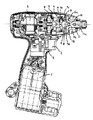
図2において、電池1と、駆動源となるモータ3と、該モータ3に電池1からの電力供給を制御するためのスイッチ2、モータ回転を減速するための減速歯車5は、ハウジング4の中に収納されている。
【0012】
モータ3の回転出力は減速歯車5からスピンドル6に伝達される。
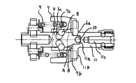
スピンドル6の軸上にはV字型のカム溝6cが刻設され、これに摺動可能に嵌合するハンマ7内周にも同様のV字型のカム溝7cがあり、鋼球8で係合されている。スピンドル6の先端には細径の嵌合軸6aが形成され、スピンドルの嵌合軸6aの先端には保持穴6eが設けてあり直径5mm程度の球形部材10がスピンドル嵌合軸6a端面から1mm程度突出するよう回転軸近傍に配置されている。この球形部材10は硬度がHrC60程度に硬く、耐摩耗性に優れている材質で有れば鋼材でも良いし、セラミックのようなものでも良い。
【0013】
アンビル11には嵌合穴11aが設けてあり、嵌合穴11の底部は平面でありスピンドル6とアンビル11が嵌合した状態で球形部材10とアンビルの嵌合穴11aの平面な底部とが突き当たり、スピンドルの側面A13とアンビルの側面B14との間には0.5mm程度の隙間がき、接触しないような寸法関係にある。
また、アンビルの先端には六角の穴11cがあり、この穴に先端が十字のドライバビット(図示せず)が挿入される。
【0014】
次にこのインパクトドライバの動作について説明する。
スイッチ2を入れると、電池1からモータ3に通電され、モータ3は約12000rpmで高速回転する。モータ3の回転は、減速歯車5で約1/8に減速され、スピンドル6は約1500rpmで回転し、スピンドル6のカム溝6cと、このスピンドル6の外周部に配置されたハンマ7のカム溝7cは、二つをつなぐ鋼球8の作用で、ハンマ7は回転するとともにスピンドル6のスラスト方向に移動し、スプリング9を圧縮する。
【0015】
ハンマ7の爪部7bとアンビルの爪部11bの噛み合いが外れるまでスプリング9を圧縮した後に両爪部が外れ、ハンマ7は圧縮したスプリング9の圧縮荷重によりカム溝6cに沿って押し戻され、さらにカム溝6cとカム溝7cとの間に配置された鋼球8を介して、スピンドル6の回転によりハンマ7が回転しながらアンビル11の方向に移動し、ハンマの爪部7bがアンビルの爪部11bに噛み合った瞬間強力にねじを締める方向に打撃し、ネジが締付けられる。
【0016】
このとき、ねじの十字穴とドライバビットが外れないように、操作者は回転打撃工具本体を押付けるが、この押付け荷重Fはスピンドル6の保持穴6eに配置した球形部材10とアンビルの嵌合穴11aの平面な底部とで、点接触により支えられるため、たとえ押付け荷重Fが大きくとも、接触部の平均半径Rは1mmに満たない非常に小さなものである。
このためスピンドルの回転ロスとなる摩擦トルクTmは、従来のスピンドルの側面A13とアンビルの端面B14で接触した場合の1/5以下に小さくできる。これによりモータ3の消費する電流も10%程度下げることができ、スピードも増し、モータの消費電流が減れば、電池一充電で締められるねじの本数を増すこともできる。
また、本発明の球形部材10は鋼材で製作されており、且つ硬く焼入れされているので、押付け荷重Fが小さな接触部に集中しても摩耗が早期に進行することを防げる。
【0017】
また、アンビルの嵌合穴11aの中にグリースなどの潤滑剤を充填しておけば球状部材10の摺動部は摩耗しにくく、また、摩擦抵抗はさらに低減され、スピンドルの嵌合軸6aで蓋されるので潤滑剤は漏れにくく、潤滑効果が持続する。
【0018】
また、機構部の組立作業において、球形部材10は転がりやすく、もし万が一、組立て途中に球形部材10がギヤボックス内に転がり落ち、これに気がつかないまま組立てしまい、回転打撃工具本体を動作させてしまうと球形部材10が本体内部で転がりまわり、回転打撃工具の破損につながる可能性がある。そこで、球形部材10はスピンドルの嵌合軸6aの先端の挿入部穴に圧入することにより、スピンドル6やハンマ7をギヤボックスに組み込む際に、球形部材10は転がり落ちるとこがなく、上記した組立不良による故障の心配がなく回転打撃工具の信頼性が増す。
【0019】
また、スピンドル6の保持穴6eの穴径が球形部材10の直径より大きくても、保持穴6eの入り口付近の直径のみを球形部材10の直径より僅かに小さくすることによっても、球形部材10の落下が防げる同様な効果が得られる。
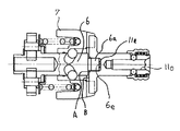
図3、図4、図5は別の実施例を説明する。
図3は、図1の変形例であり、スピンドル側に嵌合穴6dを設け、アンビル側の嵌合穴11aとの間に両端面が球状面を持つ円柱形部材12(例えばニードルローラなど)が、スピンドル側の嵌合穴6d及びアンビルの嵌合穴11aに対し、数10ミクロンの隙間ではめあうよう回転軸近傍で配置されている。
【0020】
また、円柱形部材12は、スピンドル6またはアンビル11のどちらか一方に圧入されても良く、その場合は円柱形部材12の圧入されない側の端面のみが球状面を有していれば良く、この方式でも図1の実施例同様にスピンドルの回転ロス等の原因となる摩擦トルクを小さくすることができる。さらに、球状の端面形状を持つ円柱形部材12を用いることで、球形部材10を用いる場合よりも球面の曲率を大きくすることができ、耐磨耗性がアップし寿命向上につながることが可能である。
【0021】
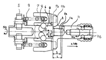
図4はスピンドルの嵌合軸6aの端面にスピンドルの突起部6fを回転軸近傍に配置し、相対するアンビルの嵌合穴11aの底部を平面にし、アンビルの嵌合穴11aの深さをスピンドルの嵌合軸6aの長さよりも0.5mm程度短くし、スピンドルの突起部6fがアンビルの嵌合穴11aの底部に突き当たった状態で、スピンドルの側面A13とアンビルの側面B14に、0.5mm程度隙間が空くように構成したものである。
この実施例も図1記載の実施例同様、ねじ締め時に押付け荷重が加わっても、スピンドル6とアンビル11とが点接触となるため接触部の平均半径が小さくなりスピンドルの回転ロス等の原因となる摩擦トルクは小さくできる。
【0022】
また、スピンドルの嵌合軸6aの端面に一体に突起部設けられているので、球形部材10が不要なため経済的であるばかりか、球形部材10が組立て中に本体内部に転がり落ちることがなくなり、組立て時の信頼性が向上するとともに、製品の信頼性も向上する。なお、スピンドルの突起部6fは球面にすることが望ましく、また球面の曲率の大きさは自由であり、また、突起部形状は球面以外の円錐状や円錐台状などでも良く、接触部の平均半径が小さくなるものであれば、同様な効果が得られることは言うまでもない。
【0023】
図5は、図4の変形例であり、スピンドル6側に嵌合穴6dを設け、アンビル11側に嵌合軸11dを設けたものである。もちろんアンビル側の嵌合軸11dの端面はアンビルの突起部11eが設けられている。この方式でも前記記載の実施例同様、スピンドルの回転ロス等の原因となる摩擦トルクの発生を小さくできるのは言うまでもないが、さらに次に上げる効果が得られる。
【0024】
図1〜図3の実施例では、アンビル11にドライバビットを挿入する六角の穴11cと、スピンドル6の嵌合軸6aまたは円柱形部材12が挿入されるアンビルの嵌合穴11aとが両端面から開けられているために、アンビル11の全長を長くする必要がある。
【0025】
しかし、図5の実施例によればアンビル11にはアンビルの嵌合穴11aの代わりに、アンビルの嵌合軸11dを設けているので、アンビル11に空ける穴はアンビルの六角穴11cのみであり、アンビル11のL2寸法を短くできるメリットがある。また、スピンドル6にスピンドルの嵌合穴11dを設けても、元々嵌合穴を設けるスペースは十分あるのでスピンドル自体の全長を変える必要がなく、スピンドル6とアンビル11を組み合わせた時の全長は短くなるので、回転打撃工具の小型化が図れる。さらにスピンドル6のスピンドルの嵌合穴6dの入り口に60度程度の面取りを施せば、スピンドル6を加工する際のセンター穴として活用できるので、スピンドル6の軸の研磨など加工が行いやすく経済的である。
【0026】
また、アンビルの突起部11eの変わりに、アンビルの嵌合軸11dに穴を設け、その穴に球形部材10を回転軸近傍に設けても良い。
また、上記してきた種種の突接部材や突起部は、複数個設けてあっても良い。
【0027】
【発明の効果】
本発明によれば、スピンドルとアンビルのスラスト方向の接触を、点接触に近い状態になるよう構成したので、接触部の平均半径が小さく、接触部の平均半径と押付け荷重できまるスピンドルの回転ロス等の原因になるの摩擦トルクが小さくでき、モータの消費電流が小さくなり、スピンドルの回転速度があがるとともに、充電式電池一充電あたりの作業量が増すことができる。
【図面の簡単な説明】
【図1】本発明の一実施例を示す回転打撃工具の部分断面図
【図2】本発明の一実施例を示す回転打撃工具の断面図
【図3】本発明の別の実施例を示す回転打撃工具の部分断面図
【図4】本発明の別の実施例を示す回転打撃工具の部分断面図
【図5】本発明の別の実施例を示す回転打撃工具の部分断面図
【図6】従来技術による回転打撃工具の断面図
【図7】従来技術による回転打撃工具の部分拡大断面図
【符号の説明】
1は電池、2はスイッチ、3はモータ、4はハウジング、5は減速歯車、6はスピンドル、6aはスピンドルの嵌合軸、6cはカム溝、6dはスピンドルの嵌合穴、6eは保持穴、6fはスピンドルの突起部、7はハンマ、7bはハンマの爪部、7cはカム溝、8は鋼球、9はスプリング、10は球形部材、11はアンビル、11aはアンビルの嵌合穴、11bはアンビルの爪部、11cはアンビルの六角穴、11dは嵌合軸、11eはアンビルの突起部、12はニードルローラ、13はスピンドル側面A、14はアンビルの側面B、Lはアンビルの嵌合穴の深さ、Sはスピンドルの嵌合軸の長さ、である。[0001]
TECHNICAL FIELD OF THE INVENTION
The present invention relates to a rotary impact tool such as an impact driver and an impact wrench.
[0002]
[Prior art]
Inside the
[0003]
The rotation of the
[0004]
When a force that hinders rotation of the
[0005]
When the
[Patent Document 1]
JP-A-2002-254336
[Patent Document 2]
JP-A-2002-273666 FIG.
FIG. 7 is an enlarged view of an engagement portion between the
[0006]
Here, in the screw tightening work using the rotary hitting tool, a screwdriver attached to the
[0007]
Due to the rotation difference between the
This frictional resistance causes the
The friction torque Tm that causes the rotation loss of the
[0008]
[Problems to be solved by the invention]
Here, the problem to be solved by the present invention is that, between the
[0009]
[Means for Solving the Problems]
The above object can reduce the friction torque (Tm) by reducing μ or Rm in the formula Tm = μ × F × Rm. Therefore, as a method of reducing Rm, a contact member (for example, a spherical member or a convex end surface) is provided between the spindle fitting shaft 6a and the anvil fitting hole 11a so that the side surface A13 of the spindle does not contact the side surface B14 of the anvil. Is arranged near the rotating shaft and the average radius Rm of the contact portion between the
[0010]
Alternatively, a similar effect can be obtained by disposing a bearing or a bearing having a low friction coefficient member between the
[0011]
BEST MODE FOR CARRYING OUT THE INVENTION
One embodiment in which the present invention is applied to a cordless impact driver operated by a rechargeable battery will be described with reference to FIGS.
In FIG. 2, a battery 1, a motor 3 serving as a drive source, a switch 2 for controlling the power supply from the battery 1 to the motor 3, and a
[0012]
The rotation output of the motor 3 is transmitted from the
A V-shaped cam groove 6c is engraved on the shaft of the
[0013]
The
A
[0014]
Next, the operation of the impact driver will be described.
When the switch 2 is turned on, power is supplied from the battery 1 to the motor 3, and the motor 3 rotates at a high speed of about 12000 rpm. The rotation of the motor 3 is reduced to about 1/8 by the
[0015]
After the
[0016]
At this time, the operator presses the rotary hitting tool body so that the screw hole and the driver bit do not come off. The pressing load F is applied by the fitting of the
For this reason, the friction torque Tm, which is the rotational loss of the spindle, can be reduced to 1/5 or less of the conventional case where the side face A13 of the spindle and the end face B14 of the anvil are in contact with each other. As a result, the current consumed by the motor 3 can be reduced by about 10%, the speed can be increased, and if the current consumed by the motor decreases, the number of screws that can be tightened with one charge of the battery can be increased.
Further, since the
[0017]
If a lubricant such as grease is filled in the fitting hole 11a of the anvil, the sliding portion of the
[0018]
Also, in assembling the mechanical part, the
[0019]
Even if the diameter of the holding hole 6 e of the
3, 4 and 5 illustrate another embodiment.
FIG. 3 is a modification of FIG. 1, in which a
[0020]
The
[0021]
FIG. 4 shows an arrangement in which a spindle projection 6f is arranged near the rotation axis on the end face of the spindle fitting shaft 6a, the bottom of the opposing anvil fitting hole 11a is made flat, and the depth of the anvil fitting hole 11a is adjusted by the spindle. The length of the spindle 6a is about 0.5 mm shorter than the length of the fitting shaft 6a. With the protrusion 6f of the spindle abutting against the bottom of the fitting hole 11a of the anvil, the side face A13 of the spindle and the side face B14 of the anvil It is configured such that a gap is provided.
In this embodiment, as in the embodiment shown in FIG. 1, even if a pressing load is applied at the time of screw tightening, the
[0022]
In addition, since the protrusion is integrally provided on the end face of the fitting shaft 6a of the spindle, the
[0023]
FIG. 5 is a modified example of FIG. 4, in which a
[0024]
In the embodiment shown in FIGS. 1 to 3, a
[0025]
However, according to the embodiment of FIG. 5, since the
[0026]
Further, instead of the protrusion 11e of the anvil, a hole may be provided in the fitting shaft 11d of the anvil, and the
In addition, a plurality of the above-mentioned various types of projecting members and projecting portions may be provided.
[0027]
【The invention's effect】
According to the present invention, since the contact between the spindle and the anvil in the thrust direction is configured to be close to the point contact, the average radius of the contact portion is small, and the rotational loss of the spindle can be reduced by the average radius of the contact portion and the pressing load. It is possible to reduce the friction torque, which causes the above, etc., reduce the current consumption of the motor, increase the rotation speed of the spindle, and increase the amount of work per charge of the rechargeable battery.
[Brief description of the drawings]
FIG. 1 is a partial cross-sectional view of a rotary impact tool showing one embodiment of the present invention. FIG. 2 is a cross-sectional view of a rotary impact tool showing one embodiment of the present invention. FIG. 3 shows another embodiment of the present invention. FIG. 4 is a partial cross-sectional view of a rotary hitting tool showing another embodiment of the present invention. FIG. 5 is a partial cross-sectional view of a rotary hitting tool showing another embodiment of the present invention. FIG. 7 is a sectional view of a rotary impact tool according to the prior art. FIG. 7 is a partially enlarged sectional view of a rotary impact tool according to the prior art.
1 is a battery, 2 is a switch, 3 is a motor, 4 is a housing, 5 is a reduction gear, 6 is a spindle, 6a is a spindle fitting shaft, 6c is a cam groove, 6d is a spindle fitting hole, and 6e is a holding hole. , 6f are spindle projections, 7 is a hammer, 7b is a hammer claw, 7c is a cam groove, 8 is a steel ball, 9 is a spring, 10 is a spherical member, 11 is an anvil, 11a is a fitting hole of an anvil, 11b is an anvil claw portion, 11c is a hexagonal hole of an anvil, 11d is a fitting shaft, 11e is a protruding portion of an anvil, 12 is a needle roller, 13 is a spindle side A, 14 is an anvil side B, and L is an anvil fitting. The depth of the mating hole, S, is the length of the fitting shaft of the spindle.
Claims (6)
前記スピンドルとアンビルの間に突き当て部材を設け、前記スピンドルと前記アンビルの回転軸に対して交わる端面との間に隙間を設けたことを特徴とする回転打撃工具。A motor serving as a drive source, a spindle rotated by the motor, a cam groove provided in the spindle, and a spherical member arranged in the cam groove are arranged to rotate and move in the axial direction of the spindle. A hammer and a rotary impact tool having an anvil that is rotated by the impact of the hammer;
A rotary striking tool, wherein a striking member is provided between the spindle and the anvil, and a gap is provided between the spindle and an end face intersecting with a rotation axis of the anvil.
Priority Applications (1)
| Application Number | Priority Date | Filing Date | Title |
|---|---|---|---|
| JP2002341993A JP2004174635A (en) | 2002-11-26 | 2002-11-26 | Rotary impact tool |
Applications Claiming Priority (1)
| Application Number | Priority Date | Filing Date | Title |
|---|---|---|---|
| JP2002341993A JP2004174635A (en) | 2002-11-26 | 2002-11-26 | Rotary impact tool |
Publications (1)
| Publication Number | Publication Date |
|---|---|
| JP2004174635A true JP2004174635A (en) | 2004-06-24 |
Family
ID=32704176
Family Applications (1)
| Application Number | Title | Priority Date | Filing Date |
|---|---|---|---|
| JP2002341993A Pending JP2004174635A (en) | 2002-11-26 | 2002-11-26 | Rotary impact tool |
Country Status (1)
| Country | Link |
|---|---|
| JP (1) | JP2004174635A (en) |
Cited By (3)
| Publication number | Priority date | Publication date | Assignee | Title |
|---|---|---|---|---|
| JP2009214226A (en) * | 2008-03-10 | 2009-09-24 | Makita Corp | Impact tool |
| JP2023087501A (en) * | 2021-12-13 | 2023-06-23 | 株式会社マキタ | impact tool |
| US12377525B2 (en) | 2021-12-13 | 2025-08-05 | Makita Corporation | Impact tool |
-
2002
- 2002-11-26 JP JP2002341993A patent/JP2004174635A/en active Pending
Cited By (5)
| Publication number | Priority date | Publication date | Assignee | Title |
|---|---|---|---|---|
| JP2009214226A (en) * | 2008-03-10 | 2009-09-24 | Makita Corp | Impact tool |
| JP2023087501A (en) * | 2021-12-13 | 2023-06-23 | 株式会社マキタ | impact tool |
| US12377525B2 (en) | 2021-12-13 | 2025-08-05 | Makita Corporation | Impact tool |
| US12390909B2 (en) | 2021-12-13 | 2025-08-19 | Makita Corporation | Impact tool |
| JP7777972B2 (en) | 2021-12-13 | 2025-12-01 | 株式会社マキタ | Impact tools |
Similar Documents
| Publication | Publication Date | Title |
|---|---|---|
| US5908076A (en) | Impact tool driver | |
| US8083117B2 (en) | Nailer device | |
| US11780060B2 (en) | Impact wrench | |
| CN110125858B (en) | Impact wrench and anvil for use therewith | |
| US7886841B2 (en) | Power tool torque overload clutch | |
| US20030150298A1 (en) | Hand-held power tool | |
| GB2424249A (en) | Power tool with overload clutch mounted in cavity in gear-cog | |
| US3848680A (en) | Impact clutch mechanism | |
| US4191264A (en) | Impact wrench | |
| US6684964B2 (en) | Hammer drill | |
| US20150034346A1 (en) | Impact Tool | |
| KR100706119B1 (en) | Rolling hammer drill | |
| JP2004174635A (en) | Rotary impact tool | |
| JP2006326830A (en) | Rotary impact tool | |
| US20070181321A1 (en) | Rolling hammer drill | |
| JP3894106B2 (en) | Impact tools | |
| US12390910B2 (en) | Driving mechanism | |
| US20070125203A1 (en) | Worm, worm gear wrench | |
| US7191848B2 (en) | Rolling hammer drill | |
| JP3678962B2 (en) | Rotating hammer tool | |
| CN101309778B (en) | screw driving machine | |
| JP2002046078A (en) | Impact tool | |
| WO2025076712A1 (en) | Impact driver hammer | |
| JP5190789B2 (en) | Electric tool | |
| JP2015160297A (en) | fastening tool |
Legal Events
| Date | Code | Title | Description |
|---|---|---|---|
| A621 | Written request for application examination |
Free format text: JAPANESE INTERMEDIATE CODE: A621 Effective date: 20050928 |
|
| A977 | Report on retrieval |
Free format text: JAPANESE INTERMEDIATE CODE: A971007 Effective date: 20070518 |
|
| A131 | Notification of reasons for refusal |
Free format text: JAPANESE INTERMEDIATE CODE: A131 Effective date: 20070529 |
|
| A521 | Written amendment |
Free format text: JAPANESE INTERMEDIATE CODE: A523 Effective date: 20070727 |
|
| A131 | Notification of reasons for refusal |
Free format text: JAPANESE INTERMEDIATE CODE: A131 Effective date: 20071204 |
|
| A02 | Decision of refusal |
Free format text: JAPANESE INTERMEDIATE CODE: A02 Effective date: 20080415 |