【0001】
【発明の属する技術分野】
本発明は、生体内組織膜(例えば、血管)に形成された経皮的に貫通した穴を縫合する際に、糸の結び目を作ることなく、縫合糸をクリップ部材によってかしめることで、簡便に縫合糸を固定することが可能な生体内組織縫合用の縫合糸留め具に関する。
【0002】
【従来の技術】
血管や他の内部構造中にカテーテル等の診断、治療用装置を挿入する低侵襲手術が広く行われている。例えば、心臓の冠状動脈の狭窄の治療において、治療処置を行うために血管中へのカテーテル等の器具を挿入することが必要となる。
【0003】
カテーテル等の血管内への挿入は、通常大腿部を切開した穿刺孔から行われる。従って、処置を終えた後には、その穿刺孔の止血をする必要があるが、大腿動脈からの出血時の血圧(出血圧力)は高く、止血作業は非常に困難であり、従来は医療従事者が1時間もの間、手で押さえ続ける等の過酷な作業が行われていた。
【0004】
近年、この止血作業を容易かつ確実に行うべく、傷穴から挿入され血管に作られた穴を縫合する縫合装置が開発されている(例えば、特許文献1参照)。
【0005】
しかしながら、このような従来の縫合装置を使用した場合においても、糸の結び目を皮下深くに位置する血管壁の表面近傍に形成する必要があるため、縫合糸を通した後に最終的に糸を結び、切断する作業は容易ではない。
【0006】
この作業を容易にするため、結び目を形成する器具(例えば、特許文献2参照)や、結び目を皮下に押し込む器具(例えば、特許文献3参照)が提案されている。
【0007】
【特許文献1】
特許第3164532号公報
【特許文献2】
米国特許USP 5217470号公報
【特許文献3】
米国特許USP 5797929号公報
【0008】
【発明が解決しようとする課題】
しかしながら、特許文献2や3に記載されたような器具を使用したとしても、結局のところ、縫合器も含めて3種類の器具を使い分けねばならず、また結び目をルーズな緩い状態に保つよう配慮しながら押し込んでいくのは容易ではない。さらに、押し込んだ後、はさみ等、別途器具を用いて糸を切断する必要もある。
【0009】
本発明は、生体内組織の縫合時に、容易かつ確実に縫合糸を留めることができる縫合糸留め具を提供することを目的とするものである。
【0010】
【課題を解決するための手段】
上記目的を達成するため、本発明は、以下の(1)〜(6)の構成を有するものである。
【0011】
(1)細径な本体部と、該本体部の基端に設けられた操作部とを有し、生体組織を縫合するための糸を留める器具であって、変形することにより前記糸に固定されるクリップ部材と、該クリップ部材を保持する保持部と、前記本体部の先端部に前記糸を通すことの可能な少なくとも一部に閉鎖された外周を備える通路を有し、前記クリップ部材は前記通路の少なくとも一部を形成することを特徴とする縫合糸留め具。
【0012】
(2)前記クリップ部材の基端部の近傍に前記糸を切断する切断部材を有することを特徴とする上記(1)に記載の縫合糸留め具。
【0013】
(3)前記操作部に、前記糸を一時的に挟持する糸挟持部を有することを特徴とする上記(1)または(2)に記載の縫合糸留め具。
【0014】
(4)前記保持部は、前記クリップ部材を圧迫することにより変形させることを特徴とする上記(1)ないし(3)のいずれかに記載の縫合糸留め具。
【0015】
(5)前記保持部は、2本以上のアーム状部材からなり、該アーム状部材の間に前記クリップ部材が保持されており、該アーム状部材を閉じることにより前記クリップ部材を圧迫することを特徴とする上記(4)に記載の縫合糸留め具。
【0016】
(6)前記本体部を構成する管状部材内は、前記アーム状部材の外側に摺動可能に設けられ、前記アーム状部材を閉じる動作は、前記アーム状部材が前記管状部材内に入り込むことにより行われることを特徴とする上記(4)に記載の縫合糸留め具。
【0017】
【発明の実施の形態】
そこで、本発明の縫合糸留め具を血管縫合時に用いるのに適した実施形態について説明する。なお、本発明の縫合糸留め具は、血管縫合糸留め具に限定されるものではなく、他の生体内組織に形成された穴の縫合の際にも利用できる。
(実施形態1)
図1は、本発明の縫合糸留め具の実施形態1の外観図である。図2は、図1に示した縫合糸留め具の断面図である。図3はクリップ部材を説明する図である。図4〜10は、図1に示した縫合糸留め具の使用状態を説明する図である。
【0018】
この実施形態1の縫合糸留め具1は、生体内組織膜に形成された経皮的に貫通した穴を縫合する縫合糸の両端を一体に留め、穴を塞ぐための器具である。縫合糸留め具1は、皮膚上に形成された穴より生体内組織内に挿入可能な細さと長さを有する本体部2を先端側に備える。また、本体部2の後端部に、操作部3が設けられている。本体部2は、管状部材4と管状部材4の管内に設置されたアーム5により形成され、アーム5は基端が操作部3のハンドル6に固定されている。アーム5は先端が所定間隔を有するよう2つに分離されており、先端には膨出部が形成されている。管状部材4の基端はフランジ形状の第1レバー7に固定されている。管状部材4と第1レバー7はアーム5上を摺動可能に設けられており、ハンドル6と第1レバー7の間にはバネ8が固定されている。バネ8は、第1レバー7を先端側に軽く押し、後述するクリップ11がアーム5から外れて落ちないように作用する。バネ8の力は、クリップ11を潰さない程度のものである。管状部材4の上には、先端に刃が形成された管状体よりなるカッターパイプ9が摺動可能に設けられている。カッターパイブ9の基端側にはフランジ状の第2レバー10が固定されている。
【0019】
本体部2の先端部、すなわちアーム5先端の膨出部を構成する間隔を有する2つの部材の内側には、クリップ11がアーム5の弾性により保持されている。クリップ11は、短い筒状体であり、内部に少なくとも2本の縫合糸を挿通させることができる内径の内腔を有する。
【0020】
本実施形態1の糸留め具1が留める対象となる縫合糸は、アーム5の先端(末端)からクリップ11の内腔を通って管状部材4に設けられた側孔12までの通路を通される。この通路は、クリップ11の側壁や、管状部材4によって周囲が閉鎖された部分を有するが故に、縫合糸が側方から抜け落ちることがない。通路には予め縫合糸と置換するためのループ状置換線材15を通しておく。ループ状置換線材15は、極細の金属線材をループ状に形成し、基端に把持部17を設けたもので、先端のループ内に縫合糸を通した後把持部17を引き抜けば、通路内に容易に縫合糸を通すことが可能となる。
【0021】
また、第1レバー7にはスリット13が、ハンドル6の基端には糸挟持部14が設けられている。糸挟持部14は縫合糸を挟むことにより固定可能な切れ込みを有しており、スリット13は縫合糸を固定した際に縫合糸をはめ込んで、位置を安定させるためのものである。
【0022】
図2に示すように、アーム5は2本の金属棒を組み合わせたものからなり、基端がハンドル6に固定され、先端には各金属棒の間に空隙を有するように段差が設けられている。また、最先端の外側には膨出部があり、空隙の間にはクリップ11が備えられている。アーム5先端の内側には、クリップ11が外れ落ちないように窪みが設けられている。窪みは、アームの両側に設けても、一方のみに設けても良いが、窪みの深さは両者を併せても後述するクリップ11を潰した状態の厚みよりも浅くするのが望ましい。具体的にはくぼみの深さはクリップ11の肉厚以下とするのが望ましい。
【0023】
クリップ11は、使用前の状態(図2a)では、内腔が広がった状態でアーム5に支えられている。この状態で、クリップ11及び側孔12(図2では破線で図示)を含む通路に縫合糸を通した後、図2bに示すように第1レバー7を先端側に押すと、ややラッパ状に拡径した管状部材4の先端がアーム5の膨出部を押さえつけ、結果アーム5が空隙を無くす方向に変形するため、クリップ11がかしめられて潰れ、塑性変形して縫合糸を留めることとなる。ここで、第1レバー7を押したときには、第2レバー10も一体的に前進する。
【0024】
次に、図2cのように第2レバー10のみを押すと、カッターパイプ9が管状部材4上を前進し、刃が形成されたカッターパイプの先端が側孔12に通された縫合糸を切断する。切断後、第1レバー7を後退させて図2aのような状態に戻すと、かしめられたクリップ11は開放され、縫合糸とともにその場に残される。なお、アーム5の先端膨出部の外表面は、管状部材4との摺動性を高めるため、研磨やコーティングなどの表面処理を行うことが望ましい。
【0025】
図3に示されるのは、クリップ11の変形例を示す断面図である。内側に糸を通す空間さえあれば、真円(a)でも楕円(b)、長円(図示せず)でも良く、潰れる方向を予測しやすいように予め潰れかけた形状(c)や切欠きを設けたC字状(d、e)でも良い。クリップ11に切欠きを設ける場合、縫合糸がかしめる前に外れないよう、切欠き部分を塞ぐようにアーム5にフィルム等変形可能な閉鎖具を設けることが好ましい。いずれの場合においても、クリップ11の内腔は、最低2本の縫合糸が挿入可能であることが望ましい。具体的には、内径0.3mm〜2mm程度が望ましい。また、クリップ11の軸方向長さは、0.3mm〜2mm程度が望ましい。クリップ11を構成する材料としては、生体適合性が高く、塑性変形可能であることが望ましい。生体埋め込み材料として実績のあるチタンやチタン合金、ステンレス(SUS316LまたはSUS304)が好適である。上記の条件を満たすことができれば、一定時間後に生体内に吸収される生体内吸収性材料も望ましい。
【0026】
次に、図4〜10を参照して、図1に示した縫合糸留め具の具体的な使用状態を説明する。
【0027】
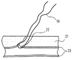
(1)まず、血管等の目的の組織に従来の縫合装置などを用いて1本以上の縫合糸16を通す。(図4)図中、20は血管、21は皮下組織を示している。22は手術に用いられた穴(パンクチャーサイト)である。
【0028】
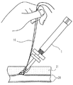
(2)次いで、縫合糸16の両端をまとめて、縫合糸用通路にセットされ本実施形態1の縫合糸留め具1の先端から突出している縫合糸誘導部材であるループ状置換線材15のループ内に通す。(図5)
(3)ループ状置換糸15の把持部17を基端側に引き抜くことで、縫合糸16はクリップ11内を含む縫合糸留め具1の通路内に挿通する。このとき、縫合糸16の両端は側孔12から外部に導き出された状態となる。(図6)
(4)次に、縫合糸16の両端を手で引っ張ることで縫合糸16に張力を与えた状態で、縫合糸留め具1を縫合糸16に沿わせて前進させる。縫合糸留め具1内の縫合糸16の通路は、閉鎖された外周を有するため、縫合糸留め具1を縫合糸16に沿わせて前進させる際に、縫合糸から縫合糸留め具1が外れることがない。前進していくと、縫合糸留め具1の細径の本体部2は、皮下組織21を通り、糸を留める(固定する)目的の場所である血管壁20の表面まで挿入される。(図7)
(5)目的の部位まで挿入したら、スリット13および糸挟持部14に縫合糸16を挟み込んで固定し、血液の漏出の有無を確認することによって縫合糸16の締め込みが十分であるか確認する。ここで、血液の漏出があれば、縫合糸16を引き、さらに縫合糸留め具1を前進させる。血液の漏出が無い場合は、縫合糸留め具1の位置をその場に決定し、第1レバー7を押し込み、アーム5を締め付けることによって、クリップ11を変形させ縫合糸16を固定する。(図8)
(6)次に、糸挟持部14によって縫合糸16を固定した状態で第2レバー10を前進させると、カッターパイプ9が前進し、側孔12を通る縫合糸16を切断する。これにより、余分な縫合糸を除去することができる。(図9)
(7)切断後、各レバーを元の位置に戻し、本縫合糸留め具1と余分な縫合糸を取り去り、クリップ11を残して縫合を完了させる。(図10)
以上のように、本発明の実施形態1では、クリップ内に縫合糸を通して所望の位置でクリップをかしめることにより、容易に糸を留めることができ、更に余分な糸を切断、除去することができる。
(実施形態2)
図11は、本発明の縫合糸留め具の実施形態2を説明する外観図であり、図12はその断面図である。前述の実施形態1との違いは、アームを締め付けるための管状部材を動作させるレバーの構造を変え、カッターパイプとハンドルを互いに固定した点である。
【0029】
この実施形態2の縫合糸留め具101は、皮膚上に形成された穴より生体内組織内に挿入可能な本体部102を先端側に備える。また、本体部102の後端部に、操作部103が設けられている。本体部102は、管状部材104と管状部材104の管内に設置されたアーム105により形成され、アーム105は基端が操作部103のハンドル106に固定されている。アーム105は先端が所定間隔を有するよう2つに分離されており、先端には膨出部が形成されている。
【0030】
管状部材104の基端は、移動台座107に固定されている。管状部材104と移動台座107はアーム105上を摺動可能に設けられており、ハンドル106と移動台座107の間にはバネ108が固定されている。バネ108は、移動台座107を先端側に軽く押し、後述するクリップ111がアーム105から外れて落ちないように作用する。バネ108の力は、クリップ111を潰さない程度のものである。管状部材104の上には、先端に刃が形成された管状体よりなるカッターパイプ109が設けられている。カッターパイブ109の基端にはカッター台座110が固定されている。
【0031】
カッター台座110とハンドル106は、レバーガイド113によって互いに固定されている。レバーガイド113には、中間部分に穴が設けられており、穴の中にはレバー116が回動可能に設けられている。レバー116は、2つの軸を有する。第1の軸117は、移動台座107と回動可能に接続されている。具体的には、移動台座107に設けられた突起部内に円柱状の棒からなる軸が貫通している。第2の軸118は、レバーガイド113に固定された円柱状の棒からなる軸が、レバー116に設けられた穴を貫通した形態で設けられている。第2の軸118のためのレバー116に形成された穴には、本体部102の軸と直交する方向へ遊びが設けられている。このような構造であるため、レバー116は第の軸118を中心に回動可能であり、レバー116の回動に伴い移動台座107および管状部材104が移動する。レバー116を基端側に倒すと、移動台座107および管状部材104は先端側に移動する。また、レバー116を先端側に倒すと、移動台座107および管状部材104は基端側に移動する。
【0032】
本体部102の先端部、すなわちアーム105先端の膨出部を構成する間隔を有する2つの部材の内側には、クリップ111がアーム105の弾性により保持されている。クリップ111は、短い筒状体であり、内部に少なくとも2本の縫合糸を挿通させることができる内径の内腔を有する。留める対象となる縫合糸が通される通路は、実施形態1と同様の構成である。具体的には、アーム105の先端(末端)からクリップ111の内腔を通って管状部材104に設けられた側孔112までの通路である。
【0033】
また、ハンドル106には糸挟持部114が設けられている。糸挟持部114は縫合糸を挟んで巻くことにより縫合糸を固定して、位置を安定させるためのものである。
【0034】
その他、アームの構造やクリップの構造は実施形態1と同様であるため、共通部分については説明を省略するが、以下に図12を用いて、本実施形態2の動作を説明する。
【0035】
使用前の状態(図12a)では、アーム105は、クリップ111を内腔が広がった状態で支えている。この状態で、クリップ111及び側孔112(図12では破線で図示)を含む通路に縫合糸を通した後、図12bに示すようにレバー116を基端側に倒すと、管状部材104が先端側に移動し、ややラッパ状に拡径した管状部材104の先端がアーム105の膨出部を押さえつけ、結果アーム105が空隙を無くす方向に変形するため、クリップ111がかしめられて潰れ、塑性変形して縫合糸を留めることとなる。
【0036】
次に、図12cのようにレバー116を先端側に倒すと、管状部材104は図12aに示す初期状態よりも更に基端側に移動し、側孔112は完全にカッターパイプ109の内側に入り込み、側孔112内を通る縫合糸は刃のついたカッターパイプ109の先端により切断される。それと同時に、アーム105が元の状態に広がるので、かしめられたクリップ111は開放され、縫合糸と共にその場に残される。
【0037】
以上のような実施形態2の縫合糸留め具101によれば、操作が容易であり、移動させる部材が一つだけであるので、片手で、かつワンタッチでクリッピング作業を行うことができる。
(実施形態3)
図13は、本発明の縫合糸留め具の実施形態3を説明する断面図である。図2に示す実施形態1との違いは、カッターパイプと、アームを締め付けるための管状部材の位置を替えた点である。また、バネはカッター用レバーと締め付け用レバーの間に設けられる。
【0038】
その他の基本的な構造は実施形態1と同様であるため、共通部分については共通の符号を用いて説明を省略する。以下に図13を用いて、本実施形態3の動作を説明する。
【0039】
クリップ11は、使用前の状態(図13a)では、内腔が広がった状態でアーム5に支えられている。アーム5は、バネ208が管状部材204の基端に設けられた第1レバー207を押しているため、クリップ11を軽く締める方向に力を加えている。この状態で、クリップ11及び管状部材204に設けられた側孔12(図13では破線で図示)を含む通路に縫合糸を通した後、図13bに示すように第1レバー207を先端側に押すと、ややラッパ状に拡径した管状部材204の先端がアーム5の膨出部を押さえつけ、結果アーム5が空隙を無くす方向に変形するため、クリップ11がかしめられて潰れ、塑性変形して縫合糸を留めることとなる。
【0040】
次に、図13cのようにカッターパイプ209の基端に設けられた第2レバー210を先端側に押すと、カッターパイプ209が管状部材204内壁に沿って前進し、外向きに刃が形成されたカッターパイプの先端が側孔12に通された縫合糸を切断する。切断後、第1レバー207および第2レバー210を後退させて図13aのような状態に戻すと、かしめられたクリップ11は開放され、縫合糸とともにその場に残される。
(実施形態4)
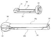
図14は、本発明の縫合糸留め具の実施形態4を説明する断面図であり、図15はカッター部材309とアーム305を説明する図である。図13に示す実施形態3とは、縫合糸を通す通路が器具全体に渡って形成されている点、管状部材には糸を通す側溝が設けられていない点、カッターがパイプ状でなく、基端側に引かれるときに糸を切断する構造となっている点などが異なる。
【0041】
本実施形態4における基本的な構造は実施形態1と同様であるため、共通部分については共通の符号を用いて説明を省略し、相違点についてのみ説明する。図15において、カッター部材309はカッターレバー310から2本の支持体351が延在し、支持体351の先端にはカッターの刃351が設けられており、刃351は、基端向きに刃面が形成されている。カッターレバー310の中央に形成された穴は、アーム305が入るためのものである。
【0042】
アーム305は2つの部品305a、305bを組み合わせて形成される。アーム305a,bそれぞれの先端には膨出部360が設けられ、2つの部品の先端側にはクリップ11を保持し、縫合糸を通すための通路としての役割を有する隙間361が形成されている。この隙間361内にカッターの刃351が摺動可能にはめ込まれる。アーム305bの基端側は、両サイドが切欠いた形状となっているが、これはカッター部材309の支持体351と嵌合するためのものである。アーム305aの基端側には、縫合糸を通すための通路となるルーメン362が形成される。
【0043】
クリップ11は、使用前の状態(図14a)では、内腔が広がった状態でアーム305に支えられている。本実施形態4においては、縫合糸16の通路は、クリップ11の内腔からアーム305の隙間361とアーム305aに形成されたルーメン362を経由して、ハンドル306に形成されたルーメン370を通り、縫合糸留め具301の基端より外部に導き出される。なお、縫合糸を通す際は、実施形態1と同様のループ状置換用線材(図示せず)の長いもの(線材部分が縫合糸留め具301の全長より長いもの)を用いることができる。なお、ハンドル306の基端部には、ネジ型の糸固定具371が設けられる。糸固定具371は、締め付けることにより、ルーメン370内の縫合糸16を固定することができる。
【0044】
図14bは、縫合糸16を通路内に通し、糸固定具371で縫合糸16を固定し、管状部材4を前進させてクリップ11をかしめた状態を示している。その後、図14cに示すようにカッターレバー310を後退させれば、カッターの刃351が後退し、アーム305bのクランク状部分に押し付けられて、縫合糸16が切断される。
【0045】
本実施形態4によれば、縫合糸を器具内部に通すため、血管壁までの挿入性に優れる。
【0046】
【発明の効果】
本発明の縫合糸留め具は、クリップを用いることによって生体内組織膜に形成された経皮的に貫通した穴を縫合するための縫合糸を結ぶことなく留めることができ、簡単な作業で容易に処理を完了することができるものである。
【0047】
また、クリップを留めた後に糸を切断できる機能を備えることにより、より簡便に縫合作業を行うことができる。
【0048】
さらには、糸を縫合糸留め具に一時的に固定する固定部を設けたことによって、クリップを留めるべき位置にあるかどうかを、血液の漏れなどを元にクリップのかしめを行う前に確認でき、確実な縫合を行うことができる。
【0049】
また、従来は糸を結ぶ必要があるため、縫合糸に腰のない繊維糸であるマルチフィラメント縫合糸を用いる必要があったが、本発明の縫合糸留め具によれば、モノフィラメント縫合糸を使用することができる。モノフィラメント縫合糸は、腰が強く、結節拡張力が強い、感染が起きにくい等の利点があるため、血管吻合などの医療現場ではマルチフィラメントよりも積極的に使用されている。
【図面の簡単な説明】
【図1】図1は、本発明の縫合糸留め具の実施形態1の外観図である。
【図2】図2は、図1に示した縫合糸留め具の動作状態を示す断面図である。
【図3】図3は、クリップのバリエーションを説明する図である。
【図4】図4は、血管に縫合糸を通した状態を示す図である。
【図5】図5は、図4に示した縫合糸を縫合糸留め具に通す直前の様子を示す図である。
【図6】図6は、図5に示した縫合糸を縫合糸留め具に通した様子を示す図である。
【図7】図7は、図6に示した縫合糸に沿って縫合糸留め具を皮下組織内に挿入した様子を示す図である。
【図8】図8は、クリップをかしめた状態を示す図である。
【図9】図9は、クリップをかしめた後、縫合糸を切断する様子を示す図である。
【図10】図10は、縫合の完了した状態を示す図である。
【図11】図11は、本発明の縫合糸留め具の実施形態2の外観図である。
【図12】図12は、図11に示した縫合糸留め具の動作状態を示す断面図である。
【図13】図13は、本発明の縫合糸留め具の実施形態3の縫合糸留め具の動作状態を示す断面図である。
【図14】図14は、本発明の縫合糸留め具の実施形態4の縫合糸留め具の動作状態を示す断面図である。
【図15】図15は、図14に示した縫合糸留め具の部品の構造を説明するための図である。
【符号の説明】
1、101、201、301 縫合糸留め具
2 本体部
3 操作部
4 管状部材
5 アーム
6 ハンドル
7 第1レバー
8 バネ
9 カッターパイプ
10 第2レバー
11 クリップ
12 側孔[0001]
TECHNICAL FIELD OF THE INVENTION
According to the present invention, when a percutaneously penetrated hole formed in an in-vivo tissue membrane (for example, a blood vessel) is sutured, the suture is swaged with a clip member without forming a knot of the thread, thereby simplifying the operation. The present invention relates to a suture fastener for suturing a tissue in a living body capable of fixing a suture to the body.
[0002]
[Prior art]
2. Description of the Related Art Minimally invasive surgery for inserting a diagnostic or therapeutic device such as a catheter into a blood vessel or other internal structure is widely performed. For example, in the treatment of coronary stenosis of the heart, it is necessary to insert an instrument such as a catheter into a blood vessel to perform a therapeutic procedure.
[0003]
The insertion of a catheter or the like into a blood vessel is usually performed through a puncture hole in which a thigh is incised. Therefore, it is necessary to stop the puncture hole after the procedure, but the blood pressure (bleeding pressure) at the time of bleeding from the femoral artery is high, and it is very difficult to stop the bleeding. However, for an hour, severe work such as holding down by hand was performed.
[0004]
In recent years, a suturing device has been developed for suturing a hole made in a blood vessel inserted from a wound hole in order to easily and reliably perform this hemostatic work (for example, see Patent Document 1).
[0005]
However, even when such a conventional suturing device is used, the knot of the thread must be formed near the surface of the blood vessel wall located deep under the skin, so that the suture is finally tied after passing the suture. The work of cutting is not easy.
[0006]
In order to facilitate this operation, a device for forming a knot (for example, see Patent Document 2) and a device for pushing a knot under the skin (for example, see Patent Document 3) have been proposed.
[0007]
[Patent Document 1]
Japanese Patent No. 3164532 [Patent Document 2]
US Patent No. 5,217,470 [Patent Document 3]
US Patent No. 5,797,929 [0008]
[Problems to be solved by the invention]
However, even if a device as described in Patent Documents 2 and 3 is used, after all, three types of devices including the suture device must be used properly, and care must be taken to keep the knot loose and loose. It is not easy to push while pushing. Furthermore, after pushing in, it is necessary to cut the thread using a separate tool such as scissors.
[0009]
SUMMARY OF THE INVENTION It is an object of the present invention to provide a suture fastener that can easily and reliably hold a suture when suturing a tissue in a living body.
[0010]
[Means for Solving the Problems]
In order to achieve the above object, the present invention has the following configurations (1) to (6).
[0011]
(1) An instrument having a small-diameter main body portion and an operation portion provided at a base end of the main body portion, which is a device for fastening a thread for suturing a living tissue, and fixed to the thread by being deformed. A clip member, a holding portion for holding the clip member, and a passage having an outer periphery closed at least in a part capable of passing the thread through a distal end portion of the main body portion, wherein the clip member is A suture fastener comprising at least a portion of the passage.
[0012]
(2) The suture fastener according to (1), further including a cutting member that cuts the thread near a base end of the clip member.
[0013]
(3) The suture fastener according to (1) or (2), wherein the operation unit includes a thread holding unit that temporarily holds the thread.
[0014]
(4) The suture fastener according to any one of (1) to (3), wherein the holding portion deforms the clip member by pressing the clip member.
[0015]
(5) The holding portion is composed of two or more arm-shaped members, and the clip member is held between the arm-shaped members, and pressing the clip member by closing the arm-shaped member. The suture fastener according to the above (4), which is characterized in that:
[0016]
(6) The inside of the tubular member constituting the main body is slidably provided outside the arm-shaped member, and the operation of closing the arm-shaped member is performed by the arm-shaped member entering the tubular member. The suture fastener according to (4), which is performed.
[0017]
BEST MODE FOR CARRYING OUT THE INVENTION
Therefore, an embodiment suitable for using the suture fastener of the present invention at the time of suturing a blood vessel will be described. In addition, the suture fastener of the present invention is not limited to a vascular suture fastener, and can be used for suturing holes formed in other in-vivo tissues.
(Embodiment 1)
FIG. 1 is an external view of a first embodiment of a suture fastener according to the present invention. FIG. 2 is a cross-sectional view of the suture fastener shown in FIG. FIG. 3 is a diagram illustrating a clip member. 4 to 10 are views for explaining a use state of the suture fastener shown in FIG.
[0018]
The suture fastener 1 according to the first embodiment is a device for closing both ends of a suture thread for suturing a percutaneously penetrated hole formed in a tissue membrane in a living body and closing the hole. The suture fastener 1 has a main body 2 having a small thickness and a length at a distal end side, which can be inserted into a tissue in a living body through a hole formed on the skin. An operation unit 3 is provided at a rear end of the main body 2. The main body 2 is formed by a tubular member 4 and an arm 5 installed in a tube of the tubular member 4, and the arm 5 has a base end fixed to a handle 6 of the operation unit 3. The arm 5 is divided into two such that the tip has a predetermined interval, and a bulge is formed at the tip. The proximal end of the tubular member 4 is fixed to a flange-shaped first lever 7. The tubular member 4 and the first lever 7 are slidably provided on the arm 5, and a spring 8 is fixed between the handle 6 and the first lever 7. The spring 8 gently pushes the first lever 7 toward the distal end, and acts so that a clip 11 described below does not come off the arm 5 and fall. The force of the spring 8 is such that the clip 11 is not crushed. On the tubular member 4, a cutter pipe 9 made of a tubular body having a blade formed at the tip is slidably provided. A flange-shaped second lever 10 is fixed to the base end side of the cutter pipe 9.
[0019]
A clip 11 is held by the elasticity of the arm 5 inside the distal end portion of the main body 2, that is, inside two members having an interval forming a bulging portion at the distal end of the arm 5. The clip 11 is a short tubular body, and has a bore having an inner diameter through which at least two sutures can be inserted.
[0020]
The suture to be fastened by the thread fastener 1 of the first embodiment passes through the passage from the distal end (end) of the arm 5 to the side hole 12 provided in the tubular member 4 through the lumen of the clip 11. You. This passage has a side wall of the clip 11 and a portion closed around by the tubular member 4, so that the suture does not fall off from the side. A loop-shaped replacement wire 15 for replacing a suture is passed through the passage in advance. The loop-shaped replacement wire 15 is formed by forming a very thin metal wire into a loop shape and providing a grip portion 17 at the base end. If the grip portion 17 is pulled out after the suture is passed through the loop at the distal end, a passage is formed. The suture can be easily passed through the inside.
[0021]
Further, a slit 13 is provided in the first lever 7, and a thread holding portion 14 is provided at a base end of the handle 6. The thread holding portion 14 has a cut that can be fixed by sandwiching the suture, and the slit 13 is used to fit the suture when the suture is fixed, thereby stabilizing the position.
[0022]
As shown in FIG. 2, the arm 5 is composed of a combination of two metal rods, the base end of which is fixed to the handle 6, and the distal end of which is provided with a step so as to have a gap between the metal rods. I have. In addition, a bulge is provided outside the foremost end, and a clip 11 is provided between gaps. A recess is provided inside the tip of the arm 5 so that the clip 11 does not come off. The depression may be provided on both sides of the arm or only one of the arms, but it is preferable that the depth of the depression is smaller than the thickness of the clip 11 to be described later when the clip 11 is crushed. Specifically, it is desirable that the depth of the depression is equal to or less than the thickness of the clip 11.
[0023]
In a state before use (FIG. 2A), the clip 11 is supported by the arm 5 in a state where the inner cavity is widened. In this state, after the suture is passed through a passage including the clip 11 and the side hole 12 (shown by a broken line in FIG. 2), the first lever 7 is pushed to the distal end side as shown in FIG. Since the distal end of the expanded tubular member 4 presses the bulged portion of the arm 5 and the arm 5 is deformed in a direction to eliminate the gap, the clip 11 is crimped and crushed, plastically deformed and the suture is fastened. . Here, when the first lever 7 is pressed, the second lever 10 also moves forward integrally.
[0024]
Next, when only the second lever 10 is pushed as shown in FIG. 2C, the cutter pipe 9 moves forward on the tubular member 4, and the tip of the cutter pipe formed with a blade cuts the suture passed through the side hole 12. I do. After cutting, when the first lever 7 is retracted and returned to the state as shown in FIG. 2A, the crimped clip 11 is released and is left in place with the suture. The outer surface of the swelling portion of the arm 5 is desirably subjected to a surface treatment such as polishing or coating in order to enhance the slidability with the tubular member 4.
[0025]
FIG. 3 is a cross-sectional view showing a modification of the clip 11. As long as there is a space to pass the thread inside, the shape may be a perfect circle (a), an ellipse (b), or an ellipse (not shown). May be C-shaped (d, e). When a notch is provided in the clip 11, it is preferable to provide a deformable closure such as a film on the arm 5 so as to close the notch so that the suture does not come off before swaging. In any case, it is desirable that at least two sutures can be inserted into the lumen of the clip 11. Specifically, the inner diameter is preferably about 0.3 mm to 2 mm. The axial length of the clip 11 is desirably about 0.3 mm to 2 mm. It is desirable that the material constituting the clip 11 be highly biocompatible and plastically deformable. Titanium, titanium alloy, and stainless steel (SUS316L or SUS304), which have been proven as bioimplant materials, are suitable. If the above conditions can be satisfied, a bioabsorbable material that is absorbed into a living body after a certain period of time is also desirable.
[0026]
Next, a specific use state of the suture fastener shown in FIG. 1 will be described with reference to FIGS.
[0027]
(1) First, one or more sutures 16 are passed through a target tissue such as a blood vessel using a conventional suturing device or the like. (FIG. 4) In the figure, reference numeral 20 denotes a blood vessel, and reference numeral 21 denotes a subcutaneous tissue. Reference numeral 22 denotes a hole (puncture site) used for the operation.
[0028]
(2) Next, the both ends of the suture 16 are put together, and the loop of the loop-shaped replacement wire 15 which is the suture guide member set in the suture passage and protruding from the tip of the suture fastener 1 of the first embodiment. Pass through. (FIG. 5)
(3) By pulling out the grip 17 of the loop-shaped replacement thread 15 toward the proximal end, the suture 16 is inserted into the passage of the suture fastener 1 including the inside of the clip 11. At this time, both ends of the suture thread 16 are led out from the side holes 12 to the outside. (FIG. 6)
(4) Next, the suture fastener 1 is advanced along the suture 16 while the tension is applied to the suture 16 by pulling both ends of the suture 16 by hand. The passage of the suture 16 within the suture fastener 1 has a closed perimeter so that when the suture fastener 1 is advanced along the suture 16, the suture fastener 1 is disengaged from the suture. Nothing. As it advances, the small diameter body 2 of the suture fastener 1 is inserted through the subcutaneous tissue 21 to the surface of the vessel wall 20 where the thread is to be fastened (fixed). (FIG. 7)
(5) When the suture 16 is inserted to the target portion, the suture 16 is sandwiched and fixed in the slit 13 and the thread holding portion 14, and it is confirmed whether or not the suture 16 is sufficiently tightened by checking for blood leakage. . If there is a leak of blood, the suture 16 is pulled, and the suture fastener 1 is further advanced. If there is no blood leakage, the position of the suture fastener 1 is determined in place, the first lever 7 is pushed in, and the arm 5 is tightened to deform the clip 11 and fix the suture 16. (FIG. 8)
(6) Next, when the second lever 10 is advanced in a state where the suture 16 is fixed by the thread holding portion 14, the cutter pipe 9 advances, and the suture 16 passing through the side hole 12 is cut. Thereby, the extra suture can be removed. (FIG. 9)
(7) After cutting, return each lever to the original position, remove the final suture fastener 1 and excess suture, and leave the clip 11 to complete suturing. (FIG. 10)
As described above, in the first embodiment of the present invention, the suture can be easily fastened by passing the suture through the clip and swaging the clip at a desired position, and the extra thread can be cut and removed. it can.
(Embodiment 2)
FIG. 11 is an external view illustrating Embodiment 2 of the suture fastener of the present invention, and FIG. 12 is a cross-sectional view thereof. The difference from the first embodiment is that the structure of the lever for operating the tubular member for tightening the arm is changed, and the cutter pipe and the handle are fixed to each other.
[0029]
The suture fastener 101 according to the second embodiment includes a main body 102 at the distal end side that can be inserted into a tissue in a living body through a hole formed on the skin. An operation unit 103 is provided at a rear end of the main body 102. The main body 102 is formed by a tubular member 104 and an arm 105 installed in a tube of the tubular member 104, and the base of the arm 105 is fixed to a handle 106 of the operation unit 103. The arm 105 is divided into two such that the tip has a predetermined interval, and a bulge is formed at the tip.
[0030]
The base end of the tubular member 104 is fixed to the movable pedestal 107. The tubular member 104 and the movable pedestal 107 are slidably provided on the arm 105, and a spring 108 is fixed between the handle 106 and the movable pedestal 107. The spring 108 gently pushes the movable pedestal 107 toward the distal end, and acts so that a clip 111 described below does not come off the arm 105 and fall. The force of the spring 108 is such that the clip 111 is not crushed. On the tubular member 104, a cutter pipe 109 made of a tubular body having a blade formed at the tip is provided. A cutter base 110 is fixed to a base end of the cutter pipe 109.
[0031]
The cutter pedestal 110 and the handle 106 are fixed to each other by a lever guide 113. The lever guide 113 has a hole at an intermediate portion, and a lever 116 is rotatably provided in the hole. Lever 116 has two axes. The first shaft 117 is rotatably connected to the movable pedestal 107. Specifically, a shaft formed of a columnar rod penetrates a projection provided on the movable base 107. The second shaft 118 is provided such that a shaft formed of a columnar rod fixed to the lever guide 113 penetrates a hole provided in the lever 116. The hole formed in the lever 116 for the second shaft 118 has play in a direction orthogonal to the axis of the main body 102. With such a structure, the lever 116 is rotatable about the second shaft 118, and the movable pedestal 107 and the tubular member 104 move with the rotation of the lever 116. When the lever 116 is tilted to the proximal end, the movable pedestal 107 and the tubular member 104 move to the distal end. When the lever 116 is tilted to the distal end, the moving pedestal 107 and the tubular member 104 move to the proximal end.
[0032]
A clip 111 is held by the elasticity of the arm 105 inside the distal end portion of the main body portion 102, that is, inside two members having an interval forming a bulging portion at the distal end of the arm 105. The clip 111 is a short tubular body and has a bore with an inner diameter through which at least two sutures can be inserted. The passage through which the suture to be fastened is the same as in the first embodiment. Specifically, it is a passage from the tip (end) of the arm 105 to the side hole 112 provided in the tubular member 104 through the lumen of the clip 111.
[0033]
The handle 106 is provided with a thread holding portion 114. The thread holding section 114 is for fixing the suture by winding the suture therebetween and stabilizing the position.
[0034]
In addition, since the structure of the arm and the structure of the clip are the same as those of the first embodiment, the description of the common parts is omitted, but the operation of the second embodiment will be described below with reference to FIG.
[0035]
In a state before use (FIG. 12A), the arm 105 supports the clip 111 in a state where the lumen is widened. In this state, the suture is passed through the passage including the clip 111 and the side hole 112 (shown by a broken line in FIG. 12), and then the lever 116 is tilted to the proximal end side as shown in FIG. Side, and the tip of the tubular member 104, whose diameter is slightly enlarged like a trumpet, presses the bulging portion of the arm 105. As a result, the arm 105 is deformed in a direction to eliminate the gap, so that the clip 111 is crimped and collapsed, and plastic deformation is caused. To fasten the suture.
[0036]
Next, when the lever 116 is tilted to the distal end side as shown in FIG. 12C, the tubular member 104 moves further to the proximal end side than the initial state shown in FIG. 12A, and the side hole 112 completely enters the inside of the cutter pipe 109. The suture passing through the side hole 112 is cut by the tip of the cutter pipe 109 having a blade. At the same time, the swaged clip 111 is released and left in place with the suture as the arm 105 expands to its original position.
[0037]
According to the suture fastener 101 of Embodiment 2 as described above, the operation is easy and only one member is moved, so that the clipping operation can be performed with one hand and one touch.
(Embodiment 3)
FIG. 13 is a cross-sectional view illustrating Embodiment 3 of the suture fastener of the present invention. The difference from the first embodiment shown in FIG. 2 is that the positions of the cutter pipe and the tubular member for tightening the arm are changed. The spring is provided between the cutter lever and the tightening lever.
[0038]
Since other basic structures are the same as those of the first embodiment, common parts are denoted by the same reference numerals and description thereof is omitted. The operation of the third embodiment will be described below with reference to FIG.
[0039]
In a state before use (FIG. 13A), the clip 11 is supported by the arm 5 in a state where the inner cavity is widened. Since the spring 208 pushes the first lever 207 provided at the base end of the tubular member 204, the arm 5 applies a force in a direction to lightly tighten the clip 11. In this state, after passing the suture through a passage including the clip 11 and the side hole 12 (shown by a broken line in FIG. 13) provided in the tubular member 204, the first lever 207 is moved to the distal end side as shown in FIG. 13B. When pushed, the tip of the tubular member 204, which has a slightly enlarged trumpet shape, presses the bulging portion of the arm 5, and as a result, the arm 5 is deformed in a direction to eliminate the gap, so that the clip 11 is crimped and collapsed, and plastically deformed. The suture will be fastened.
[0040]
Next, when the second lever 210 provided at the base end of the cutter pipe 209 is pushed to the distal end side as shown in FIG. 13C, the cutter pipe 209 advances along the inner wall of the tubular member 204, and the blade is formed outward. The tip of the cutter pipe cuts the suture passed through the side hole 12. After the cutting, when the first lever 207 and the second lever 210 are retracted and returned to the state as shown in FIG. 13A, the swaged clip 11 is released and is left in place with the suture.
(Embodiment 4)
FIG. 14 is a cross-sectional view illustrating Embodiment 4 of the suture fastener of the present invention, and FIG. 15 is a view illustrating a cutter member 309 and an arm 305. Embodiment 3 shown in FIG. 13 differs from Embodiment 3 in that a passage for passing a suture is formed over the entire instrument, that a tubular member is not provided with a side groove for passing a thread, that the cutter is not pipe-shaped, The difference is that the yarn is cut when it is pulled to the end.
[0041]
Since the basic structure of the fourth embodiment is the same as that of the first embodiment, the description of the common parts will be omitted by using the same reference numerals, and only the differences will be described. In FIG. 15, a cutter member 309 has two supports 351 extending from a cutter lever 310, and a cutter blade 351 is provided at a distal end of the support 351, and the blade 351 has a blade surface facing in a proximal direction. Is formed. The hole formed in the center of the cutter lever 310 is for the arm 305 to enter.
[0042]
The arm 305 is formed by combining two parts 305a and 305b. A bulging portion 360 is provided at the tip of each of the arms 305a and 305b, and a gap 361 is formed on the tip side of the two components to hold the clip 11 and serve as a passage for passing a suture. . The blade 351 of the cutter is slidably fitted in the gap 361. The base end of the arm 305b has a shape in which both sides are cut out, and this is for fitting with the support 351 of the cutter member 309. A lumen 362 serving as a passage for passing a suture is formed on the base end side of the arm 305a.
[0043]
In a state before use (FIG. 14A), the clip 11 is supported by the arm 305 in a state where the inner cavity is widened. In the fourth embodiment, the passage of the suture 16 passes through the lumen 370 formed in the handle 306 from the lumen of the clip 11 via the gap 361 of the arm 305 and the lumen 362 formed in the arm 305a. The suture fastener 301 is led out from the proximal end. When passing the suture, a long loop-shaped replacement wire (not shown) similar to that of the first embodiment (the wire portion is longer than the entire length of the suture fastener 301) can be used. At the base end of the handle 306, a thread-type thread fixture 371 is provided. The suture fixing tool 371 can fix the suture 16 in the lumen 370 by tightening.
[0044]
FIG. 14B shows a state in which the suture 16 is passed through the passage, the suture 16 is fixed by the thread fixing tool 371, and the tubular member 4 is advanced to caulk the clip 11. Thereafter, as shown in FIG. 14C, when the cutter lever 310 is retracted, the cutter blade 351 is retracted, pressed against the crank-shaped portion of the arm 305b, and the suture 16 is cut.
[0045]
According to the fourth embodiment, since the suture thread is passed through the inside of the device, it is excellent in insertability to the blood vessel wall.
[0046]
【The invention's effect】
ADVANTAGE OF THE INVENTION The suture fastener of this invention can fasten without tying the suture for suturing the percutaneously penetrated hole formed in the in-vivo tissue membrane by using a clip, and can be easily performed by a simple operation. Can complete the process.
[0047]
Further, by providing a function of cutting the thread after the clip is fastened, the suturing operation can be performed more easily.
[0048]
In addition, the provision of a fixing part to temporarily fix the thread to the suture fastener allows the user to confirm whether the clip is in the position to be fastened before caulking the clip based on blood leakage etc. And secure suturing can be performed.
[0049]
In addition, conventionally, since it was necessary to tie a thread, it was necessary to use a multifilament suture, which is a fiber thread having no rigidity, but according to the suture fastener of the present invention, a monofilament suture is used. can do. Monofilament sutures have advantages such as strong stiffness, strong knot dilatation, and difficulty in infection, and are more actively used than multifilaments in medical sites such as vascular anastomosis.
[Brief description of the drawings]
FIG. 1 is an external view of a first embodiment of a suture fastener according to the present invention.
FIG. 2 is a cross-sectional view showing an operation state of the suture fastener shown in FIG. 1;
FIG. 3 is a diagram illustrating a variation of a clip.
FIG. 4 is a diagram showing a state in which a suture is passed through a blood vessel.
FIG. 5 is a view showing a state immediately before passing the suture shown in FIG. 4 through a suture fastener.
FIG. 6 is a view showing a state where the suture shown in FIG. 5 is passed through a suture fastener.
FIG. 7 is a view showing a state where the suture fastener is inserted into the subcutaneous tissue along the suture shown in FIG. 6;
FIG. 8 is a diagram illustrating a state in which a clip is swaged.
FIG. 9 is a view showing a state in which a suture is cut after a clip is swaged.
FIG. 10 is a diagram showing a state where suturing is completed.
FIG. 11 is an external view of a second embodiment of the suture fastener of the present invention.
FIG. 12 is a cross-sectional view showing an operation state of the suture fastener shown in FIG. 11;
FIG. 13 is a cross-sectional view showing an operation state of the suture fastener according to the third embodiment of the present invention.
FIG. 14 is a cross-sectional view illustrating an operation state of the suture fastener according to the fourth embodiment of the present invention.
FIG. 15 is a view for explaining the structure of parts of the suture fastener shown in FIG. 14;
[Explanation of symbols]
DESCRIPTION OF SYMBOLS 1, 101, 201, 301 Suture fastener 2 Body part 3 Operation part 4 Tubular member 5 Arm 6 Handle 7 First lever 8 Spring 9 Cutter pipe 10 Second lever 11 Clip 12 Side hole