JP2004173408A - Portable telephone and charging method used for it - Google Patents
Portable telephone and charging method used for it Download PDFInfo
- Publication number
- JP2004173408A JP2004173408A JP2002335907A JP2002335907A JP2004173408A JP 2004173408 A JP2004173408 A JP 2004173408A JP 2002335907 A JP2002335907 A JP 2002335907A JP 2002335907 A JP2002335907 A JP 2002335907A JP 2004173408 A JP2004173408 A JP 2004173408A
- Authority
- JP
- Japan
- Prior art keywords
- charging
- battery
- mobile phone
- current
- terminal
- Prior art date
- Legal status (The legal status is an assumption and is not a legal conclusion. Google has not performed a legal analysis and makes no representation as to the accuracy of the status listed.)
- Granted
Links
Images


Classifications
-
- Y—GENERAL TAGGING OF NEW TECHNOLOGICAL DEVELOPMENTS; GENERAL TAGGING OF CROSS-SECTIONAL TECHNOLOGIES SPANNING OVER SEVERAL SECTIONS OF THE IPC; TECHNICAL SUBJECTS COVERED BY FORMER USPC CROSS-REFERENCE ART COLLECTIONS [XRACs] AND DIGESTS
- Y02—TECHNOLOGIES OR APPLICATIONS FOR MITIGATION OR ADAPTATION AGAINST CLIMATE CHANGE
- Y02D—CLIMATE CHANGE MITIGATION TECHNOLOGIES IN INFORMATION AND COMMUNICATION TECHNOLOGIES [ICT], I.E. INFORMATION AND COMMUNICATION TECHNOLOGIES AIMING AT THE REDUCTION OF THEIR OWN ENERGY USE
- Y02D30/00—Reducing energy consumption in communication networks
- Y02D30/70—Reducing energy consumption in communication networks in wireless communication networks
-
- Y—GENERAL TAGGING OF NEW TECHNOLOGICAL DEVELOPMENTS; GENERAL TAGGING OF CROSS-SECTIONAL TECHNOLOGIES SPANNING OVER SEVERAL SECTIONS OF THE IPC; TECHNICAL SUBJECTS COVERED BY FORMER USPC CROSS-REFERENCE ART COLLECTIONS [XRACs] AND DIGESTS
- Y02—TECHNOLOGIES OR APPLICATIONS FOR MITIGATION OR ADAPTATION AGAINST CLIMATE CHANGE
- Y02E—REDUCTION OF GREENHOUSE GAS [GHG] EMISSIONS, RELATED TO ENERGY GENERATION, TRANSMISSION OR DISTRIBUTION
- Y02E60/00—Enabling technologies; Technologies with a potential or indirect contribution to GHG emissions mitigation
- Y02E60/10—Energy storage using batteries
Abstract
Description
【0001】
【発明の属する技術分野】
本発明は携帯電話機及びそれに用いる充電方法に関し、特に携帯電話機に用いられる電池の充電方法に関する。
【0002】
【従来の技術】
従来、携帯電話機においては、図4に示すように、携帯電話の通信を行う携帯電話回路(通信回路)41と、充電動作を行う充電制御回路42と、定電流充電を行うための定電流源43と、定電圧充電を行うための定電圧源44と、定電流充電と定電圧充電とを切替えるためのスイッチ45と、充電電流及び電圧を検出するための電流電圧検出回路46と、ダイオード47とから構成され、充電器2及び電池3に接続されている。
【0003】
この携帯電話機4における正常動作時に充電を行う際の電池電圧と充電電流との関係を図5に示し、充電完了直前に通信状態になった場合の電池電圧と充電電流との関係を図6に示す。
【0004】
一般に、携帯電話機4の充電器2では、初期充電として低電流A0(A)にて定電流充電を開始し、電圧がV0(V)からV1(V)に上昇することを確認し、V3(V)での定電圧充電へ移行する。
【0005】
上記の携帯電話機に用いられる電池の充電方法としては、卓上充電器を使用することで、外部インタフェースを使用したデータ通信を行いながらの充電を可能とする方法(例えば、特許文献1参照)、充電中に受信動作を頻繁に行い、非充電中には電力が供給されていないので、消費電流を低減するために、受信処理の頻度を下げる方法(例えば、特許文献2参照)、充電中に着信があった場合に、充電器から携帯電話を外すと着信応答する方法(例えば、特許文献3参照)、充電中に消費電流の多い動作をした時に充電完了しないうちにタイムアウトしないように、過充電防止タイマを停止させて、タイムアウトしないように制御し、消費電流が多い場合に充電を継続しつづける方法(例えば、特許文献3参照)等がある。
【0006】
【特許文献1】
特開平8−130773号公報(第3〜5頁、図1,2)
【特許文献2】
特開平8−181750号公報(第2,3頁、図1)
【特許文献3】
特開平8−204790号公報(第3,4頁、図1)
【特許文献4】
特開平11−252813号公報(第3〜5頁、図1)
【0007】
【発明が解決しようとする課題】
上述した従来の携帯電話機に用いられる電池の充電方法では、図5に示すように、V3(v)での定電圧充電中に充電電流量が減少し、A2(A)以下になったことによって充電完了かどうかを判定している。
【0008】
しかしながら、従来の携帯電話機では、通信中における消費電流が非通信中の消費電流に対して極めて多く、非通信中に検出可能であった充電電流量のA2(A)を検出することが非常に困難である。
【0009】
この場合には、図6に示すのように、充電電流がA2(A)になることなく、A3(A)で収束してしまうため、充電が完了せずに継続され、充電電圧V2(V)を印加し続けてしまう。結果として、従来の携帯電話機では、電池に対して負荷をかけることになり、電池の老朽化を加速してしまうという問題がある。この問題は上記の特許文献1〜4の技術では解決することができない。
【0010】
そこで、本発明の目的は上記の問題点を解消し、正しく充電動作を検出することができ、電池への過充電という負荷を低減しかつ電池からの電力消費をなくして通信を継続することができる携帯電話機及びそれに用いる充電方法を提供することにある。
【0011】
【課題を解決するための手段】
本発明による携帯電話機は、自端末の電源に用いる電池を充電器で充電可能な携帯電話機であって、前記電池の充電動作と自端末への電力供給動作とを分けて行うように制御する制御手段を備えている。
【0012】
本発明による充電方法は、自端末の電源に用いる電池を充電器で充電可能な携帯電話機の充電方法であって、前記携帯電話機側に、前記電池の電流電圧を検出する第1のステップと、その検出結果に応じて前記電池の充電動作と前記携帯電話機への電力供給動作とを分けて行うように制御する第2のステップとを備えている。
【0013】
すなわち、本発明の携帯電話機の充電方法は、充電中に通信状態に移行した場合に電池から外部電源に電力供給源を切替えることで、装置の通信状態を保証しながら、正しい充電完了を検出し、充電を完了させることによって、電池の負荷を低減することが可能となる。
【0014】
上記のように、本発明の携帯電話機の充電方法では、通信中に電力源を切替えることで、電池への充電動作を正常に行いながら、外部の充電器からの電力を直接使用することで、正しく充電動作を検出でき、電池への過充電という負荷を低減し、電池からの電力消費をなくして通信を継続することが可能となる。
【0015】
【発明の実施の形態】
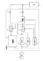
次に、本発明の実施例について図面を参照して説明する。図1は本発明の一実施例による携帯電話機の構成を示すブロック図である。図1において、携帯電話機1は携帯電話機としての携帯電話回路(通信回路)11と、充電回路(図中において12〜19の各素子を含む)とからなり、充電器2及び電池3に接続されている。
【0016】
充電回路は充電動作を行う充電制御回路12と、定電流充電を行うための定電流源13と、定電圧充電を行うための定電圧源14と、定電流充電と定電圧充電とを切り替えるためのスイッチ15と、充電電流及び電圧を検出するための電流電圧検出回路16と、ダイオード17,19と、携帯電話回路11への電力供給を電池3からの供給か、定電圧源14からの供給かを切替えるためのスイッチ18とから構成されている。
【0017】
充電制御回路12は電流電圧検出回路16の検出結果及び携帯電話回路11からの通信/非通信の情報を入力し、これらの情報に基づいてスイッチ15,18及び定電流源13を制御する。
【0018】
図2は本発明の一実施例による充電回路の動作時の電流と電圧との関係を示す図であり、図3は図1の充電制御回路12による制御動作を示すフローチャートである。これら図1〜図3を参照して本発明の一実施例による充電回路の動作について説明する。
【0019】
充電制御回路12は電流電圧検出回路16の検出結果を基にスイッチ15及び定電流源13の電流値を制御することで、図2に示すように、定電流充電と定電圧充電及び充電完了の検出を行う。
【0020】
充電制御回路12は充電開始時に(図3ステップS1)、スイッチ15を定電流源側に切替え、A0(A)の定電流での充電を実施する(図3ステップS2)。充電制御回路12は初期充電によって電池電圧がV0(V)からV1(V)に上昇したことを検出すると(図3ステップS3)、スイッチ15を定電圧源側に切替え、定電圧V3(V)での定電圧充電に切替える(図3ステップS4)。
【0021】
充電制御回路12は定電圧にて充電中に電流電圧回路が充電電流がA2(A)以下になった時に(図3ステップS7)、充電完了としてスイッチ15をOFF設定にする(図3ステップS8)。
【0022】
一方、充電制御回路12は充電動作中に携帯電話回路11から通信開始の通知がくると(図3ステップS5)、スイッチ18を電池3側から定電圧源14側に切替える(図3ステップS6)。
【0023】
これによって、携帯電話回路11の電力消費は電池3からではなく、定電圧源14側に切替えられ、電池3の充電状態(電流及び電圧)には変化なく、例えば時刻T3で通信が開始されても、電流電圧検出回路16で充電電流がA2(A)以下になったことも検出することが可能になる。
【0024】
このように、本実施例では、通信中に電力源を切替えることで、電池3への充電動作を正常に行いながら、外部の充電器2のからの電力を直接使用することで、正しく充電動作を検出することができ、電池3への過充電という負荷を低減し、電池3からの電力消費をなくして通信を継続することが可能となる。
【0025】
尚、本実施例ではスイッチ18を用いて通信中の電力源として、充電器2からの入力を定電圧源14を介して使用しているが、定電圧源出力に切替えることなく、電池3を電力供給源として継続使用し、スイッチ15を切替えることで、通信状態に入った場合に充電動作を停止する制御のみを行うことも可能である。この場合には、電池3への充電が停止しているため、通信中に電池電力を消費することになる。
【0026】
【発明の効果】
以上説明したように本発明は、自端末の電源に用いる電池を充電器で充電可能な携帯電話機において、電池の電流電圧を検出し、その検出結果に応じて電池の充電動作と携帯電話機への電力供給動作とを分けて行うように制御することによって、正しく充電動作を検出することができ、電池への過充電という負荷を低減しかつ電池からの電力消費をなくして通信を継続することができるという効果が得られる。
【図面の簡単な説明】
【図1】本発明の一実施例による携帯電話機の構成を示すブロック図である。
【図2】本発明の一実施例による充電回路の動作時の電流と電圧との関係を示す図である。
【図3】図1の充電制御回路による制御動作を示すフローチャートである。
【図4】従来の携帯電話機の構成を示すブロック図である。
【図5】充電完了時の電池電圧と充電電流との関係を示す図である。
【図6】充電完了直前に通信動作になった場合の電池電圧と充電電流との関係を示す図である。
【符号の説明】
1 携帯電話機
2 充電器
3 電池
11 携帯電話回路
12 充電制御回路
13 定電流源
14 定電圧源
15,18 スイッチ
16 電流電圧検出回路
17,19 ダイオード[0001]
TECHNICAL FIELD OF THE INVENTION
The present invention relates to a mobile phone and a charging method used for the same, and more particularly, to a method for charging a battery used in a mobile phone.
[0002]
[Prior art]
Conventionally, in a mobile phone, as shown in FIG. 4, a mobile phone circuit (communication circuit) 41 for performing communication of the mobile phone, a charging control circuit 42 for performing a charging operation, and a constant current source for performing constant
[0003]
FIG. 5 shows the relationship between the battery voltage and the charging current when the mobile phone 4 performs charging during normal operation, and FIG. 6 shows the relationship between the battery voltage and the charging current when the mobile phone 4 enters the communication state immediately before the completion of charging. Show.
[0004]
Generally, the
[0005]
As a method of charging a battery used in the above-described mobile phone, a method of enabling charging while performing data communication using an external interface by using a desktop charger (for example, see Patent Document 1), In order to reduce current consumption, a method of reducing the frequency of reception processing is performed (for example, see Patent Document 2) because reception operation is frequently performed during charging and power is not supplied during non-charging. If the mobile phone is disconnected from the charger when there is a response (for example, refer to Patent Document 3), overcharging is performed so as not to time out before completion of charging when an operation that consumes a large amount of current is performed during charging. There is a method in which the prevention timer is stopped so as not to time out, and charging is continued when the current consumption is large (for example, see Patent Document 3).
[0006]
[Patent Document 1]
JP-A-8-130773 (
[Patent Document 2]
JP-A-8-181750 (
[Patent Document 3]
JP-A-8-204790 (
[Patent Document 4]
JP-A-11-252813 (
[0007]
[Problems to be solved by the invention]
In the conventional method of charging a battery used in a mobile phone, as shown in FIG. 5, the amount of charging current decreases during constant voltage charging at V3 (v) and becomes less than or equal to A2 (A). It is determined whether charging is completed.
[0008]
However, in the conventional mobile phone, the current consumption during communication is much larger than the current consumption during non-communication, and it is very difficult to detect the charging current amount A2 (A) that can be detected during non-communication. Have difficulty.
[0009]
In this case, as shown in FIG. 6, the charging current does not become A2 (A) but converges at A3 (A), so that charging is continued without being completed, and the charging voltage V2 (V ) Is continuously applied. As a result, the conventional mobile phone has a problem that a load is imposed on the battery and the aging of the battery is accelerated. This problem cannot be solved by the techniques of
[0010]
Therefore, an object of the present invention is to solve the above-described problems, correctly detect a charging operation, reduce the load of overcharging the battery, and continue communication without consuming power from the battery. It is an object of the present invention to provide a mobile phone and a charging method used therefor.
[0011]
[Means for Solving the Problems]
A mobile phone according to the present invention is a mobile phone capable of charging a battery used as a power supply of its own terminal with a charger, and controls to perform charging operation of the battery and power supply operation to its own terminal separately. Means.
[0012]
The charging method according to the present invention is a method for charging a mobile phone capable of charging a battery used as a power supply of the terminal with a charger, and includes, on the mobile phone side, a first step of detecting a current voltage of the battery. A second step of controlling the charging operation of the battery and the power supply operation to the mobile phone separately according to the detection result.
[0013]
That is, the mobile phone charging method of the present invention detects a correct charging completion while guaranteeing the communication status of the device by switching the power supply source from the battery to the external power source when the mobile phone shifts to the communication status during charging. By completing the charging, the load on the battery can be reduced.
[0014]
As described above, in the method of charging a mobile phone according to the present invention, by switching the power source during communication, while performing normal charging operation to the battery, directly using power from an external charger, The charging operation can be correctly detected, the load of overcharging the battery can be reduced, and communication can be continued without consuming power from the battery.
[0015]
BEST MODE FOR CARRYING OUT THE INVENTION
Next, embodiments of the present invention will be described with reference to the drawings. FIG. 1 is a block diagram showing a configuration of a mobile phone according to one embodiment of the present invention. In FIG. 1, a
[0016]
The charging circuit includes a charging control circuit 12 for performing a charging operation, a constant
[0017]
The charge control circuit 12 inputs the detection result of the current /
[0018]
FIG. 2 is a diagram showing a relationship between current and voltage during operation of the charging circuit according to one embodiment of the present invention, and FIG. 3 is a flowchart showing a control operation by the charging control circuit 12 of FIG. The operation of the charging circuit according to one embodiment of the present invention will be described with reference to FIGS.
[0019]
The charge control circuit 12 controls the current values of the
[0020]
At the start of charging (step S1 in FIG. 3), the charge control circuit 12 switches the
[0021]
The charge control circuit 12 sets the
[0022]
On the other hand, the charge control circuit 12 switches the
[0023]
As a result, the power consumption of the
[0024]
As described above, in the present embodiment, the charging operation is correctly performed by directly using the power from the
[0025]
In the present embodiment, the input from the
[0026]
【The invention's effect】
As described above, the present invention detects a current and voltage of a battery in a mobile phone capable of charging a battery used as a power supply of the terminal with a charger, and performs a battery charging operation and a mobile phone charging operation in accordance with the detection result. By controlling the power supply operation separately from the power supply operation, the charging operation can be correctly detected, the load of overcharging the battery can be reduced, and communication can be continued without consuming power from the battery. The effect that can be obtained is obtained.
[Brief description of the drawings]
FIG. 1 is a block diagram showing a configuration of a mobile phone according to one embodiment of the present invention.
FIG. 2 is a diagram showing the relationship between current and voltage during operation of the charging circuit according to one embodiment of the present invention.
FIG. 3 is a flowchart showing a control operation by a charge control circuit of FIG. 1;
FIG. 4 is a block diagram showing a configuration of a conventional mobile phone.
FIG. 5 is a diagram showing a relationship between a battery voltage and a charging current when charging is completed.
FIG. 6 is a diagram illustrating a relationship between a battery voltage and a charging current when a communication operation is performed immediately before completion of charging.
[Explanation of symbols]
REFERENCE SIGNS
Claims (10)
前記制御手段は、前記第1及び第2の切替手段を制御して前記電池の充電動作と自端末への電力供給動作とを分けて行うことを特徴とする請求項1から請求項4のいずれか記載の携帯電話機。A constant current source for performing constant current charging of the battery, a constant voltage source for performing constant voltage charging of the battery, and switching between the constant current source and the constant voltage source to connect to the battery; First switching means, and second switching means for switching between the charger and the battery and connecting to a circuit in the terminal itself,
5. The control device according to claim 1, wherein the control unit controls the first and second switching units to perform a charging operation of the battery and an operation of supplying power to the own terminal separately. 6. Or the described mobile phone.
前記第2のステップは、前記第1及び第2の切替手段を制御して前記電池の充電動作と前記携帯電話機への電力供給動作とを分けて行うことを特徴とする請求項6から請求項9のいずれか記載の充電方法。Connecting a constant current source for performing constant current charging to the battery and a constant voltage source for performing constant voltage charging to the battery by a first switching unit, and connecting the battery to the battery; Switching between the charger and the battery by the switching means to connect to a circuit in the mobile phone,
7. The method according to claim 6, wherein the second step controls the first and second switching units to perform an operation of charging the battery and an operation of supplying power to the mobile phone separately. 8. 10. The charging method according to any one of the above items 9.
Priority Applications (1)
| Application Number | Priority Date | Filing Date | Title |
|---|---|---|---|
| JP2002335907A JP4144336B2 (en) | 2002-11-20 | 2002-11-20 | Mobile phone and charging method used therefor |
Applications Claiming Priority (1)
| Application Number | Priority Date | Filing Date | Title |
|---|---|---|---|
| JP2002335907A JP4144336B2 (en) | 2002-11-20 | 2002-11-20 | Mobile phone and charging method used therefor |
Publications (2)
| Publication Number | Publication Date |
|---|---|
| JP2004173408A true JP2004173408A (en) | 2004-06-17 |
| JP4144336B2 JP4144336B2 (en) | 2008-09-03 |
Family
ID=32699880
Family Applications (1)
| Application Number | Title | Priority Date | Filing Date |
|---|---|---|---|
| JP2002335907A Expired - Fee Related JP4144336B2 (en) | 2002-11-20 | 2002-11-20 | Mobile phone and charging method used therefor |
Country Status (1)
| Country | Link |
|---|---|
| JP (1) | JP4144336B2 (en) |
Cited By (4)
| Publication number | Priority date | Publication date | Assignee | Title |
|---|---|---|---|---|
| JP2004187351A (en) * | 2002-11-29 | 2004-07-02 | Nec Corp | Portable telephone and charging method thereof |
| JP2007329000A (en) * | 2006-06-07 | 2007-12-20 | Mitsubishi Electric Corp | Charging protecting device of battery |
| JP2012110167A (en) * | 2010-11-19 | 2012-06-07 | Konica Minolta Medical & Graphic Inc | Charging system |
| JP2012239286A (en) * | 2011-05-11 | 2012-12-06 | Fujitsu Ltd | Electronic apparatus and charge control circuit |
-
2002
- 2002-11-20 JP JP2002335907A patent/JP4144336B2/en not_active Expired - Fee Related
Cited By (4)
| Publication number | Priority date | Publication date | Assignee | Title |
|---|---|---|---|---|
| JP2004187351A (en) * | 2002-11-29 | 2004-07-02 | Nec Corp | Portable telephone and charging method thereof |
| JP2007329000A (en) * | 2006-06-07 | 2007-12-20 | Mitsubishi Electric Corp | Charging protecting device of battery |
| JP2012110167A (en) * | 2010-11-19 | 2012-06-07 | Konica Minolta Medical & Graphic Inc | Charging system |
| JP2012239286A (en) * | 2011-05-11 | 2012-12-06 | Fujitsu Ltd | Electronic apparatus and charge control circuit |
Also Published As
| Publication number | Publication date |
|---|---|
| JP4144336B2 (en) | 2008-09-03 |
Similar Documents
| Publication | Publication Date | Title |
|---|---|---|
| JP2914259B2 (en) | Portable electronic device and charge control method for portable electronic device | |
| JP4486618B2 (en) | Charging circuit, charging circuit operation control method, and power supply device | |
| JP2747971B2 (en) | Power supply device for portable information processing equipment and driving method thereof | |
| KR101538498B1 (en) | Method and appratus for battery gaging in portable terminal | |
| US20140159655A1 (en) | Integrated circuit for wireless charging and operating method thereof | |
| EP2624407A2 (en) | Method and apparatus for charging battery | |
| KR100584324B1 (en) | Apparatus for controlling power in complex mobile terminal | |
| JP2005151632A (en) | Charge/feed control method, and charging/feeding system | |
| JP3401886B2 (en) | Power system using batteries | |
| KR20190054708A (en) | Method for reducing standby-power and electronic device thereof | |
| WO2004025930A1 (en) | Multi-mode communication terminal | |
| JP2004173408A (en) | Portable telephone and charging method used for it | |
| JP5233500B2 (en) | Power supply control circuit and power supply control method for portable electronic device | |
| JP2004247995A (en) | Mobile telephone set | |
| US5569965A (en) | Control method for reducing quiescent current | |
| JP2000236635A (en) | Power supply system | |
| JP2004187351A (en) | Portable telephone and charging method thereof | |
| CN109445566B (en) | OTG (on-the-go) power-saving processing method and system, storage medium and mobile terminal | |
| JP2007028772A (en) | Charger, charging method and charging program | |
| JP3827665B2 (en) | Charging circuit and charging control method in portable communication device | |
| JPH1115540A (en) | Semiconductor integrated circuit | |
| JP2002354694A (en) | Electronic device having battery charger function | |
| JP2005012931A (en) | Charge control circuit, charge control method, and electronic apparatus | |
| CN111987754A (en) | Mobile device and control method for supplying power to load | |
| JP2002215274A (en) | Power consumption reduction system |
Legal Events
| Date | Code | Title | Description |
|---|---|---|---|
| A621 | Written request for application examination |
Free format text: JAPANESE INTERMEDIATE CODE: A621 Effective date: 20051014 |
|
| A977 | Report on retrieval |
Free format text: JAPANESE INTERMEDIATE CODE: A971007 Effective date: 20070226 |
|
| A131 | Notification of reasons for refusal |
Free format text: JAPANESE INTERMEDIATE CODE: A131 Effective date: 20070320 |
|
| A521 | Request for written amendment filed |
Free format text: JAPANESE INTERMEDIATE CODE: A523 Effective date: 20070514 |
|
| A131 | Notification of reasons for refusal |
Free format text: JAPANESE INTERMEDIATE CODE: A131 Effective date: 20071023 |
|
| A521 | Request for written amendment filed |
Free format text: JAPANESE INTERMEDIATE CODE: A523 Effective date: 20071217 |
|
| TRDD | Decision of grant or rejection written | ||
| A01 | Written decision to grant a patent or to grant a registration (utility model) |
Free format text: JAPANESE INTERMEDIATE CODE: A01 Effective date: 20080527 |
|
| A01 | Written decision to grant a patent or to grant a registration (utility model) |
Free format text: JAPANESE INTERMEDIATE CODE: A01 |
|
| A61 | First payment of annual fees (during grant procedure) |
Free format text: JAPANESE INTERMEDIATE CODE: A61 Effective date: 20080609 |
|
| R150 | Certificate of patent or registration of utility model |
Free format text: JAPANESE INTERMEDIATE CODE: R150 |
|
| FPAY | Renewal fee payment (event date is renewal date of database) |
Free format text: PAYMENT UNTIL: 20110627 Year of fee payment: 3 |
|
| FPAY | Renewal fee payment (event date is renewal date of database) |
Free format text: PAYMENT UNTIL: 20110627 Year of fee payment: 3 |
|
| FPAY | Renewal fee payment (event date is renewal date of database) |
Free format text: PAYMENT UNTIL: 20120627 Year of fee payment: 4 |
|
| FPAY | Renewal fee payment (event date is renewal date of database) |
Free format text: PAYMENT UNTIL: 20120627 Year of fee payment: 4 |
|
| FPAY | Renewal fee payment (event date is renewal date of database) |
Free format text: PAYMENT UNTIL: 20130627 Year of fee payment: 5 |
|
| S111 | Request for change of ownership or part of ownership |
Free format text: JAPANESE INTERMEDIATE CODE: R313113 |
|
| R350 | Written notification of registration of transfer |
Free format text: JAPANESE INTERMEDIATE CODE: R350 |
|
| LAPS | Cancellation because of no payment of annual fees |