JP2004173291A - Image processing apparatus - Google Patents
Image processing apparatus Download PDFInfo
- Publication number
- JP2004173291A JP2004173291A JP2003405940A JP2003405940A JP2004173291A JP 2004173291 A JP2004173291 A JP 2004173291A JP 2003405940 A JP2003405940 A JP 2003405940A JP 2003405940 A JP2003405940 A JP 2003405940A JP 2004173291 A JP2004173291 A JP 2004173291A
- Authority
- JP
- Japan
- Prior art keywords
- paper
- sheet
- job
- printing
- Prior art date
- Legal status (The legal status is an assumption and is not a legal conclusion. Google has not performed a legal analysis and makes no representation as to the accuracy of the status listed.)
- Granted
Links
- 238000012545 processing Methods 0.000 title claims abstract description 140
- 238000000034 method Methods 0.000 description 85
- 230000008569 process Effects 0.000 description 83
- 230000035611 feeding Effects 0.000 description 79
- 230000032258 transport Effects 0.000 description 29
- 238000010586 diagram Methods 0.000 description 28
- 230000004044 response Effects 0.000 description 13
- 238000004891 communication Methods 0.000 description 11
- 238000007906 compression Methods 0.000 description 11
- 230000004087 circulation Effects 0.000 description 9
- 230000006835 compression Effects 0.000 description 9
- 230000006837 decompression Effects 0.000 description 9
- 238000001994 activation Methods 0.000 description 7
- 230000005540 biological transmission Effects 0.000 description 7
- 238000001514 detection method Methods 0.000 description 6
- 238000012546 transfer Methods 0.000 description 6
- 230000004913 activation Effects 0.000 description 5
- 210000000078 claw Anatomy 0.000 description 5
- 230000010365 information processing Effects 0.000 description 5
- 238000002360 preparation method Methods 0.000 description 5
- 238000006243 chemical reaction Methods 0.000 description 4
- 238000012937 correction Methods 0.000 description 4
- 239000011521 glass Substances 0.000 description 4
- 238000010438 heat treatment Methods 0.000 description 4
- 230000003111 delayed effect Effects 0.000 description 3
- 238000007599 discharging Methods 0.000 description 3
- 230000006870 function Effects 0.000 description 3
- 239000004065 semiconductor Substances 0.000 description 3
- 238000003705 background correction Methods 0.000 description 2
- 230000015572 biosynthetic process Effects 0.000 description 2
- 238000012840 feeding operation Methods 0.000 description 2
- 238000012544 monitoring process Methods 0.000 description 2
- 101150046368 PSF1 gene Proteins 0.000 description 1
- 230000032683 aging Effects 0.000 description 1
- 238000004364 calculation method Methods 0.000 description 1
- 238000007405 data analysis Methods 0.000 description 1
- 230000000694 effects Effects 0.000 description 1
- 238000007730 finishing process Methods 0.000 description 1
- 239000012943 hotmelt Substances 0.000 description 1
- 238000002347 injection Methods 0.000 description 1
- 239000007924 injection Substances 0.000 description 1
- 239000004973 liquid crystal related substance Substances 0.000 description 1
- 230000007246 mechanism Effects 0.000 description 1
- 230000002093 peripheral effect Effects 0.000 description 1
- 238000013139 quantization Methods 0.000 description 1
- 238000011084 recovery Methods 0.000 description 1
- 230000001360 synchronised effect Effects 0.000 description 1
- 230000007723 transport mechanism Effects 0.000 description 1
Images


Landscapes
- Facsimiles In General (AREA)
- Accessory Devices And Overall Control Thereof (AREA)
- Record Information Processing For Printing (AREA)
- Control Or Security For Electrophotography (AREA)
Abstract
Description
この発明は画像処理装置に関し、特にジョブの割込が可能な画像処理装置に関する。 The present invention relates to an image processing apparatus, and more particularly to an image processing apparatus capable of interrupting a job.
この発明に興味のある割込ジョブの可能な画像処理装置がたとえば特開平4−233555号公報に開示されている。同公報によれば、割込ジョブが印字可能になれば、通常ジョブの実行を中断し、割込ジョブの実行に移行される。 An image processing apparatus capable of executing an interrupt job of interest to the present invention is disclosed in, for example, Japanese Patent Application Laid-Open No. Hei 4-233555. According to the publication, when an interrupt job becomes printable, execution of a normal job is interrupted, and execution is shifted to execution of an interrupt job.
従来の割込ジョブが可能な画像処理装置は上記のように構成されていた。しかしながら、従来の画像処理装置においては、割込ジョブが印字可能になれば通常ジョブの実行を中断し、割込ジョブの実行に移行していたが、割込ジョブのコピーモードがたとえば両面原稿で4in1両面コピー等の節約コピーモードでは、1枚の用紙に印字すべき画像データを確定するには原稿を8枚読込まなればならない。最初に原稿8枚を読込んで印字を開始したとしても、次の8枚の原稿読込を終了するまでは次の印字を開始することができないため、無駄な待ち時間を要するという問題があった。 A conventional image processing apparatus capable of performing an interrupt job has been configured as described above. However, in the conventional image processing apparatus, when the interrupt job becomes printable, the execution of the normal job is interrupted, and the process is shifted to the execution of the interrupt job. In the saving copy mode such as 4-in-1 double-sided copying, eight originals must be read in order to determine the image data to be printed on one sheet. Even if the eight originals are read first and printing is started, the next printing cannot be started until the reading of the next eight originals is completed, so that there is a problem that a wasteful waiting time is required.
この発明は上記のような問題点を解消するためになされたもので、効率よく割込ジョブおよび通常ジョブの実行が可能な画像処理装置を提供することを目的とする。 SUMMARY OF THE INVENTION The present invention has been made to solve the above problems, and has as its object to provide an image processing apparatus capable of efficiently executing an interrupt job and a normal job.
請求項1に係る、通常ジョブの実行中に別のジョブの割込の可能な画像処理装置は、前記各ジョブに対応する入力画像データを印字のために予めメモリに展開する手段と、前記展開された画像データを用紙上に印字する印字手段と、先行ジョブの実行中にその用紙の間隔を検出する手段と、前記検出された用紙間隔内に割込ジョブの実行が可能か否かを判断する手段と、前記判断手段が前記割込ジョブの実行が可能であると判断したときは、前記割込ジョブを前記先行ジョブと同時に実行する手段とを含む。
2. The image processing apparatus according to
通常ジョブまたは割込ジョブの進行中にその用紙の間隔を検出し、その用紙間隔内に現在実行されていないジョブの実行が可能であればそのジョブを併せて実行するため、効率よく割込ジョブおよび通常ジョブの実行が可能な画像処理装置が提供できる。 The interval of the paper is detected while a normal job or an interrupt job is in progress, and if a job that is not currently executed within the paper interval can be executed, the job is executed together. Also, an image processing apparatus capable of executing a normal job can be provided.
以下この発明の実施の形態を図面を参照して説明する。 Hereinafter, embodiments of the present invention will be described with reference to the drawings.
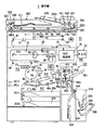
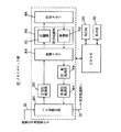
図1は、本発明に係る画像処理装置の一例としての複写機1の全体構成を示す断面図である。図1を参照して、複写機1は、イメージリーダIRと、ページプリンタPRTとから構成されたデジタル複写機であり、FAX機能を果たすFAXコントローラ50も有している。イメージリーダIRの本体は、原稿ガラス18上に載置された原稿を画素に分解して読取る走査系10と、走査系10が出力する光電変換信号の量子化と種々の画像形成モードに応じた信号処理とを行なう画像信号処理部20と、原稿に対応した画像データを記憶するメモリユニット部30から構成されている。そして、この本体の上部に原稿カバーを兼ねた付加装置である自動原稿送り装置(ADFR)500がその後端部を支点に開閉可能に設けられている。
FIG. 1 is a cross-sectional view showing an entire configuration of a
走査系10は、ライン走査方式の画像読取り機構であって、原稿照射用ランプ11と、ミラー12とを有したスキャナ19と、固定ミラー13a,13bと、集光レンズ14と、CCDアレイからなるイメージセンサ16と、スキャナ19を駆動するスキャンモータM2から構成されている。画像信号処理部20およびメモリユニット部30については後述する。
The
ADFR500は、原稿スタッカ510上にセットされた原稿を、給紙ローラ501、捌きローラ502、捌きパッド503、中間ローラ504、レジストローラ505および搬送ベルト506によって原稿台ガラス18上に搬送し、読取後の原稿を排紙ローラ509によって原稿排出トレイ511上に排出する。ADFR500には、原稿スケール512、原稿の有無を検出する原稿センサSE50、原稿サイズセンサSE51、および排出センサSE52が設けられている。
The ADFR 500 conveys the original set on the
たとえば複数枚の原稿のコピーに際して、オペレータは、原稿をその表面を上側に向けて重ねてセットする。原稿スタッカ510上の各原稿は、最下部の原稿から1枚ずつ引出され、表面を下側に向けて原稿台ガラス18上の読取位置に正確にセットされる。そして、片面原稿モードの場合には、読取終了後、原稿は図の左方向に搬送され、上面が表面となるように排出される。また、両面原稿モードの場合には、表面読取終了後に左方向に送られた原稿は、反転ローラ507によって表裏が反転されて原稿台ガラス18上の読取位置に戻され、裏面の読取終了後に再び左方向に送られて排出される。
For example, when copying a plurality of originals, the operator sets the originals with the front surfaces thereof facing upward. Each original on the
ページプリンタPRTは、露光制御信号を出力する印字処理部40と、半導体レーザ62を光源とするプリントヘッド60と、感光体ドラム71とその周辺装置からなる現像・転写系70Aと、定着ローラ対84および排出ローラ85などを有した定着・排出系70Bと、再給紙ユニット600を含む循環式の用紙搬送系70Cなどから構成され、イメージリーダIRから転送された画像データに基づいて電子写真プロセスによって複写画像をプリントする。ページプリンタPRTの下部には、数百枚程度の用紙を収納できる2つの用紙カセット80a,80bと、用紙サイズ検出センサSE11,12および給紙用ローラ群が設けられている。
The page printer PRT includes a
半導体レーザ62から射出されたレーザビ―ムは、ポリゴンミラー65で主走査方向に偏向され、主レンズ69および各種のミラー67a,68,67cを経て感光体ドラム71の露光位置に導かれる。感光体ドラム71の表面は帯電チャージャ72によって一様に帯電する。露光により形成された潜像は、現像器73を経てトナー像となり、そのトナー像は転写位置(複写位置)で転写チャージャ75により感光体ドラム71から分離され、搬送ベルト83によって定着ローラ対84へ送られ、フェースアップで排出される。
The laser beam emitted from the
再給紙ユニット600は、両面コピーを自動化するための付加装置としてページプリンタPRTの側面に組付けられている。排出ローラ85によりページプリンタ本体から排出された用紙を一旦収納し、スイッチバック搬送を行なってページプリンタ本体に送り返す機能を有している。
The
再給紙ユニット600は、再給紙部625と、切換爪604を介してその下部に設けられたバインド部631とを含む。再給紙部625は排出ローラ85から排出された用紙を一旦収納して両面モードのときは表裏を反転して、合成モードのときには表裏反転を行なわずに、再度の画像形成(プリント)のために搬送系70Bの水平搬送ローラ86aに搬入する循環式のものである。再給紙ユニット600は、排紙トレイ621への排出と再給紙とを切換えるための切換爪601、搬送ロ―ラ602、反転ローラ603および反転センサSE61などから構成されている。
The
片面コピーモードにおいて、用紙は再給紙ユニット600を素通りして排紙トレイ621上に排出される。これに対して両面コピーモードにおいては、図示しないソレノイドによって切換爪601上の左端部が上方へ移動し、排出ローラ85から排出された用紙は、搬送ローラ602を通って正反転ローラ603に達する。用紙後端が用紙センサSE61に達すると、正反転ローラ603が反転する。これによって、用紙はページプリンタ本体に戻される。戻された用紙は、水平搬送ロ―ラ86a,86b,86cを通ってタイミングローラ82に送られて待機する。ここで、複数枚の用紙が連続給紙された場合は、各用紙が互いに重ならないように所定の用紙間隔を隔てて次々に搬送されて再給紙ユニット600に送り込まれる。用紙の搬送経路長は一定であるので、再給紙ユニット600および水平搬送ローラ86a〜86cによる一循環の用紙枚数(最多循環枚数)Nは、用紙サイズに依存することになる。
In the one-sided copy mode, the sheet is discharged onto the
再給紙ユニット600はフィニッシング処理を行なう排紙オプションを有する。排紙オプションとしてのホットメルト方式のバインド部631は、バインド処理を自動化するための付加装置としてページプリンタPRTの側面に設けられている。排出ローラ85によりページプリンタ本体から排出された用紙を一旦バインド部631へ搬送した後、所定枚数収納した時点でバインドしてバインド排出トレイ636へ排出される。
The
バインドなしの通常コピーにおいては、用紙はバインド部を通ることなく排出トレイ621上へ排出される。
In the normal copy without binding, the sheet is discharged onto the
バインドモードにおいては、用紙を搬送する前に予めバインドカバー収納トレイ630からバインドカバーが給紙されて、バインド部631へ搬送され、バインドカバーの先端がバインド搬送ローラ632の上部に接して待機している。
In the bind mode, before the paper is conveyed, the bind cover is fed in advance from the bind
この状態で用紙がページプリンタPRTから排出されると、図示しないソレノイドによって切換爪604の上部が左へ移動し、用紙はバインド用紙排出ロ―ラ633によりバインド部631へ搬送される。所定枚数分バインド部へ用紙が排出されると、バインド押え板634が左方向へ移動し、用紙とバインドカバーを密着させた後、バインド搬送ローラ632により搬送される。それによってバインド加熱板635へ圧接され、所定時間加熱された後バインド加熱板635が下方へ移動し、さらにバインド搬送ローラ632により搬送されてバインドされた束がバインド排出トレイ636へ排出される。なおバインド加熱板を加熱するためのバインドヒ―タ637が設けられている。
When the sheet is discharged from the page printer PRT in this state, the upper portion of the
図2は操作パネルOPの平面図である。操作パネルOPには、状態表示および各種のモード指定およびジョブの登録のための液晶タッチパネル91と、コピーの数値条件(枚数や倍率など)を入力するためのテンキー92と、数値条件を標準値に戻すためのクリアキ―93と、コピーモードを初期化するためのパネルリセットキー94と、コピー中止を指示するためのストップキー95と、コピー開始を指示するためのスタートキー96と、Nin1コピーであるか片面原稿であるか両面原稿であるかを指定するための原稿指定キー97と両面コピーと片面コピーとを切換えるためのコピーモードキ―101と、割込起動および復帰を入力するための割込キー102、バインドモードを選択するバインドモード選択キー99などが配置されるている。ここでNin1コピーとは、1枚の用紙にN枚の原稿をコピーするモードをいう。バインドモードが選択されるとバインドモード表示部99aに表示される。
FIG. 2 is a plan view of the operation panel OP. The operation panel OP includes a liquid
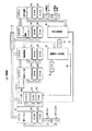
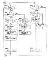
図3および図4は複写機1の制御部100の構成を示すブロック図である。制御部100は8個のCPU1〜CPU8を中心に構成され、これら各CPU1〜CPU8には、それぞれプログラムを格納したROM111〜ROM118が設けられている。なお、CPU6はメモリユニット部30内に設けられている。
3 and 4 are block diagrams showing the configuration of the
CPU1は、操作パネルOPの各種操作キ―からの信号入力や表示の制御を行なう。CPU2は、画像信号処理部20の各部の制御を行ない、CPU3は走査系10の駆動制御を行なう。CPU4は、印字処理部40を含むページプリンタPRTの制御を行なう。
The
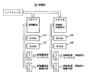
CPU5は、制御部100の全体的なタイミング調整、および動作モードの設定のための処理を行なう。そのため、CPU5は、他のCPUとのシリアル通信を行なって、制御に必要なコマンドやレポートなどの送受を行なう。
The
CPU6は、画像情報の記憶および読出の制御を行なう。CPU7は、ADFR500による原稿搬送の制御を行なう。そして、CPU8は再給紙ユニット600の制御を行なう。
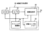
図5は画像信号処理部20の構成を示すブロック図である。画像信号処理部20は、A/D変換部21と、画像処理部22と、画像モニタ用メモリ23およびこれら各部の動作の同期信号を出力するタイミング制御部24から構成されている。
FIG. 5 is a block diagram showing a configuration of the image
A/D変換部21は、イメージセンサ16の光電変換信号を量子化して8ビット(256階調)の画像データに変換する。画像処理部22は、シェーディング補正、MTF補正、ガンマ補正および変倍処理などの画像処理を行ない、処理後の画像データD2を読取情報として出力する。画像モニタ用メモリ23は、シェーディング補正のためのサンプルデータの記憶などに用いられる。
The A /
図6はメモリユニット部30の構成を示すブロック図である。メモリユニット部30は、バス切換部301と、2値化処理部302と、マルチポートの画像メモリ304と、圧縮器311および伸張器312とを有した符号処理部305と、マルチポートの符号メモリ306と、回転処理部308と、多値化処理部309およびこれらを制御する上述のCPU6を有し、メモリの小容量化のために画像情報を圧縮して記憶するように構成されている。なお、画像メモリ304は、400dpiの解像度で読取った2ページ分の画像データの記憶が可能な容量を有する。
FIG. 6 is a block diagram showing the configuration of the
原稿走査(スキャン)によって読取った画像を一旦記憶するメモリモードのコピーにおいて、メモリユニット部30の2値化処理部302には、画像信号処理部20からバス切換部301を介して8ビットの画像データD2が入力される。2値化処理部302には、たとえばディザ法などによって多値の画像データD2を復元可能な範囲で2値の画像データに変換する処理を行なう。2値化後の画像データは、画像メモリ304に一旦書込まれる。
In the copy in the memory mode in which the image read by the original scanning (scan) is temporarily stored, the
符号処理部305は画像メモリ304に書込まれた画像データを読出しかつ圧縮して符号データ(圧縮データ)を生成し、それを符号メモリ306に書込む。また、符号処理部305は、プリントの対象となる符号データを符号メモリ306から読出して伸張し、得られた画像データを画像メモリ304に書込む。なお、圧縮器311および伸張器312は、コピー速度の向上のために互いに独立してかつ平行に動作可能に構成されている。これらと符号メモリ306との間では、デ―タがそれぞれ図示しないDMAコントローラによりDMA転送されるようになっている。
The
伸張により1ページ分の画像データが再生されると、そのデータが画像メモリ304から読出され、必要に応じて回転処理を施された後、多値化処理部309で多値の画像データに復元される。そして、その多値の画像データが露光制御データとして印字処理部40へ転送される。このような原稿画像の一時的な記憶に際して、符号メモリ306はRAM126内に設けられた管理テーブルMT1によって管理される。
When one page of image data is reproduced by decompression, the data is read out from the
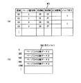
図7は管理テーブルMT1と符号メモリ306との関係を示す図である。符号メモリ306は、32Kバイト単位のメモリ領域に区分されており、書込(読取時)と読出(プリント時)との同時制御を可能とすることを考慮して、それぞれの領域にはページごとの符号データが格納される。
FIG. 7 is a diagram showing the relationship between the management table MT1 and the
管理テーブルMT1には、符号メモリ306の領域を示す番号、書込順(原稿のスキャン順)に付与される画像データのページ番号(原稿画像の番号)PN、連結されている領域の番号、および圧縮方式およびデータ長などの圧縮伸張処理や、ジョブを区別するために必要な各種の付加情報が格納されており、これらの情報に基づいて符号メモリ306を動的に管理するようになっている。
The management table MT1 includes a number indicating an area of the
図7(a)における「前連結」は、各ページ内における32Kバイトごとの領域の前方向へのつながりを示すものであり、、これが「00」である場合には1ページ分のデータの最初の格納領域であることを示す。「後連結」もそれと同様に、「FF」である場合に最後の領域であることを示し、「FF」以外の場合には後につながる領域の番号を示す。 The “previous link” in FIG. 7A indicates a forward link of an area of 32 Kbytes in each page, and when this is “00”, the start of one page of data is Indicates that this is a storage area. Similarly, "post-link" indicates the last area when it is "FF", and indicates the number of the area connected later when it is other than "FF".
CPU106は、画像メモリ304から画像データを読出して圧縮する際に、管理テーブルMT1の情報を作成しながら、圧縮器311を制御して符号メモリ306に格納していく。また、画像データを出力する際には、それと逆の動作により符号メモリ306から符号データを読出していく。管理テーブルMT1内の情報は、該当ページの情報が正常に読出され、オペレータの指定した枚数(部数)Mのコピーが完了したときに消去される。
When reading and compressing image data from the
次に、メモリモードにおける複写機1の動作シーケンスについて、各CPU1〜CPU6の間でやり取りされる要求コマンド(Q)、レポート(A)、またはデータの流れを中心に説明する。
Next, an operation sequence of the copying
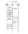
図8はメモリモード書込動作の概略のシーケンスを示す図である。メモリモード書込動作では、画像信号処理部20から画像メモリ304へ画像データが転送される。まず、全体のシーケンスを管理しているCPU5が、CPU6に対してメモリ準備を要求する。これを受けて、CPU6は内部ハードウェアに対し、画像信号処理部20からの画像データD2を画像メモリ304へ転送するためのバス接続状態の設定、2値化処理のためのモードの設定、画像メモリ304への書込領域の開始アドレスおよびXYレングス情報などの設定を行なう。
FIG. 8 is a diagram showing a schematic sequence of the memory mode write operation. In the memory mode writing operation, image data is transferred from the image
これらの設定が終わって準備が完了すると、CPU6はCPU5に対してメモリ準備の完了を通知する。CPU5がCPU6,CPU2に対して読取を要求すると、CPU2がCPU3に対してスキャンを要求する。CPU3によりスキャンが開始されてスキャナ19が画像領域に達すると、CPU2により設定された画像処理モードに応じて、読取データ(画像データD2)が画像信号処理部20からメモリユニット部30に転送される。
When these settings are completed and the preparation is completed, the
スキャンが終了し、CPU2,CPU6から読取の完了が通知されると、CPU5はCPU6に対してデータ圧縮を要求する。これを受けて、CPU6は、画像メモリ304からの読出アドレス、XYレングス情報、符号メモリ306への書込アドレスおよび圧縮器311のモード(たとえばMH方式)などを設定し、各部の起動を行なう。これによって圧縮処理が行なわれ、符号データが符号メモリ306に格納される。
When the scan is completed and the completion of the reading is notified from the
圧縮処理が完了すると、CPU6からCPU5に圧縮の完了を通知する。このとき、符号メモリ306が一杯になっていた場合には、圧縮不可能を示すパラメータを付加した圧縮完了レポートがCPU5に送られる。これによって、CPU5は符号メモリ306がフルメモリ状態になったことを知ることができる。
When the compression process is completed, the
図9はメモリモード読出動作の概略のシーケンスを示す図である。メモリモード読出動作では、画像メモリ304から画像データが読出され、その画像デ―タに基づいて用紙に複写画像がプリントされる。
FIG. 9 is a diagram showing a schematic sequence of the memory mode read operation. In the memory mode reading operation, image data is read from the
CPU5はCPU6に対してデータ伸張を要求する。CPU6は、符号メモリ306からの読出アドレス、データ量、画像データ304への書込アドレス、XYレングス情報および伸張器312のモード(たとえばMH方式)などを設定して各部の起動を行なう。これによって伸張処理が行なわれ、画像データが画像メモリ304に書込まれる。
The
伸張処理が終了すると、CPU5はCPU6に対して画像メモリ304から画像データを読出すためのメモリ準備要求を要求する。これを受けて、CPU6は内部ハードウェアに対して画像メモリ304から印字処理部40へ画像データD3を出力するためのバス接続状態の設定、回転処理のための設定、画像メモリ304の読出領域の開始アドレスおよびXYレングス情報などの設定を行なう。
When the decompression process is completed, the
これらの設定が終わって準備が完了し、その通知を受取ると、CPU5はCPU6、CPU4に対してプリントを要求する。CPU4からCPU5に用紙の搬送状態を知らせる給紙レポートが送られ、その後、画像メモリ304から読出された画像データD3が印字処理部40に出力されプリントが行なわれる。
When these settings are completed and preparation is completed, and the notification is received, the
プリントが終了すると、CPU6、CPU4がCPU5に対してプリント完了レポートおよびインジェクト完了レポートを送る。これらのレポートを受取ったCPU5は、必要に応じてCPU6に対してメモリクリア要求を与える。
When printing is completed, the
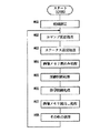
以下、フローチャートに基づいて、本発明の特徴である制御を中心に複写機1の動作をさらに詳しく説明する。図10は操作パネルOPの制御を担うCPU1のメインフローチャートである。
Hereinafter, the operation of the copying
電源が投入されると、CPU1はまだRAM121やレジスタなどを初期化する初期設定を行なう(♯11)。その後、1ルーチンの長さを規定する内部タイマのセット(♯12)、キー操作を受付けるキー入力処理(♯13)、操作に応じた表示を行なうパネル表示処理(♯14)、その他の処理(♯15)および内部タイマの打合わせ(♯16)を繰返し実行する。また、適時に割込処理として他のCPUとの通信を行なう。
When the power is turned on,
図11はキー入力処理のフローチャートである。CPU1は原稿指定キー97(図2参照)のオンに呼応して、その時点の原稿モードに応じて片面原稿モ―ド、両面原稿モードおよびNin1コピーモードに切換える。そして、切換えた後のモードをCPU5に通知する(♯301〜♯305)。
FIG. 11 is a flowchart of the key input process. In response to the ON operation of the original designating key 97 (see FIG. 2), the
同様に、コピーモードキー101のオンに呼応して、コピーモードを片面コピーモードまたは両面コピーモードに切換え、割込キー101のオンに呼応して読込モードを割込モードまたは通常読込モードに切換え、その旨をCPU5に通知する(♯306〜♯315)。また、スタートキー96がオンされると、その旨をCPU5に通知する(♯316,♯317)。
Similarly, in response to the ON of the
図12はページプリンタPRTの制御を担うCPU4のメインフローチャートである。CPU4は、初期設定(♯41)を行なった後、内部タイマのセット(♯42)、現像・転写系の制御(♯43)、搬送系の制御(♯44)、定着系の制御(♯45)、印字処理部の制御(♯46)、その他の処理(♯47)および内部タイマの待ち合わせ(♯48)を繰返し実行する。
FIG. 12 is a main flowchart of the
図13は複写機1の制御を統括するCPU5のメインフローチャートであり、図14はメモリユニット部30の制御を担うCPU6のメインフローチャートである。
FIG. 13 is a main flowchart of the
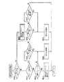
CPU5は、初期設定(♯51)を行なった後、内部タイマのセット(♯52)、他のCPUからの入力データをチェックする入力データ解析処理(♯53)、操作内容に応じて動作モードを定めるモード設定処理(♯54)、割込切換処理(♯55)、モードに応じたコマンド設定処理(♯56)、コマンドを通信ポートに待機させる出力データセット(♯57)、その他の処理(♯58)および内部タイマの待ち合わせ(♯59)を繰返し実行する。
After performing the initial setting (# 51), the
CPU6は、初期設定処理(♯61)を行なった後、コマンド受信処理(♯62)、ステータス送信処理(♯63)、画像メモリ書込処理(♯64)、圧縮制御処理(♯65)、伸張制御処理(♯66)、画像メモリ読出処理(♯67)およびその他の処理(♯68)を繰返し実行する。
After performing the initial setting process (# 61), the
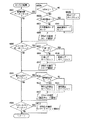
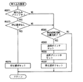
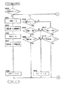
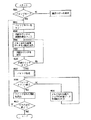
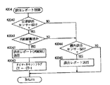
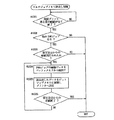
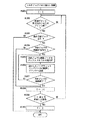
図15は図13の割込切換処理のフローチャートである。まず、割込プリント中かどうかを判断する(♯5500)。割込プリント中でない場合は、CPU1からスタート要求を受信しているかどうかをチェックする(♯5501)。スタート要求があった場合は通常プリント中かどうか判断し(♯5509)、通常プリント中の場合は割込プリントを割込ジョブの設定モードに応じて最適なタイミングで起動するために割込プリント要求をセットする(♯5511)。 FIG. 15 is a flowchart of the interrupt switching process of FIG. First, it is determined whether interruption printing is being performed (# 5500). If interrupt printing is not in progress, it is checked whether a start request has been received from CPU 1 (# 5501). If there is a start request, it is determined whether or not normal printing is being performed (# 5509). If normal printing is being performed, an interrupt print request is issued to start interrupt print at an optimum timing according to the setting mode of the interrupt job. Is set (# 5511).
スタート要求が存在しない場合は、既に割込プリント要求がセットされているかどうかチェックし(♯5503)、要求があれば、割込起動処理のサブル―チンをコールする(♯5520)。割込プリント要求がセットされていない場合は、割込プリント待ち判断を行ない(♯5505)、割込プリント待ち状態かどうか判断する(♯5506)。割込プリント待ち状態であれば、原稿読込中でまだ印字すべきデータが確定していない状態、または割込ジョブがペーパーエンプティ等のエラーでプリントできない状態になっている。したがって、通常ジョブのプリントに再度切換えるために、割込復帰処理のサブルーチンをコールする(♯5570)。割込プリント待ち状態でないときは、割込ジョブが終了したかどうか判断し(♯5507)、終了していれば割込からの自動復帰のために割込復帰処理を行なう(♯5570)。 If there is no start request, it is checked whether an interrupt print request has already been set (# 5503), and if there is a request, a subroutine for interrupt activation processing is called (# 5520). If the interrupt print request has not been set, an interrupt print wait determination is made (# 5505), and it is determined whether or not the printer is in an interrupt print wait state (# 5506). In the interrupt print waiting state, the original is being read and the data to be printed has not been determined yet, or the interrupt job cannot be printed due to an error such as paper empty. Therefore, in order to switch back to the printing of the normal job, the subroutine of the interrupt return process is called (# 5570). If it is not in the interrupt print waiting state, it is determined whether or not the interrupt job has been completed (# 5507), and if it has been completed, interrupt return processing is performed for automatic recovery from the interrupt (# 5570).
図16は図15の割込起動処理のフローチャートである。まず通常プリント中であるかどうか判断する(♯5521)。さらに停止要求が発生していないことを判断する(♯5523)。上記2つの条件が成立すれば、割込ジョブの給紙モード設定による通常ジョブの停止または継続の判定に移行する。 FIG. 16 is a flowchart of the interrupt activation process of FIG. First, it is determined whether or not normal printing is being performed (# 5521). Further, it is determined that a stop request has not been issued (# 5523). If the above two conditions are satisfied, the process shifts to the determination of the stop or continuation of the normal job by setting the paper feed mode of the interrupt job.
APSモードであれば、原稿サイズ検出が終了しているかどうかを判断し、終了していれば割込ジョブにおけるAPSモードの給紙口検索処理を行なう(♯5525、5527、5529)。マニュアル給紙口指定であれば、既に給紙口が決定しているので、直ちに通常ジョブのプリント中の給紙口と決定された割込ジョブのプリント給紙口を比較する(♯5531)。同一でなければ、すぐに通常ジョブの給紙を停止する必要があるので停止要求をセットする(♯5533)。同一であれば、通常ジョブにおける給紙を継続しながら割込プリントに移行する処理を続けて行なう。以上のように、割込ジョブのモード設定における給紙口選択モードがAPSモードである場合は、通常ジョブの印字を継続し、割込ジョブの原稿サイズを検出して給紙口が確定した時点で通常ジョブを継続するか否かを決定する。 In the case of the APS mode, it is determined whether or not the document size detection has been completed, and if it has been completed, the paper feed port search processing of the APS mode in the interrupt job is performed (# 5525, 5527, 5529). If the manual sheet feeding port is designated, since the sheet feeding port has already been determined, the sheet feeding port for printing the normal job is immediately compared with the print sheet feeding port for the determined interrupt job (# 5531). If they are not the same, it is necessary to immediately stop feeding the normal job, so a stop request is set (# 5533). If they are the same, the process of shifting to the interrupt printing is continued while the paper feeding in the normal job is continued. As described above, when the paper feed port selection mode in the interrupt job mode setting is the APS mode, printing of the normal job is continued, and when the paper size of the interrupt job is detected and the paper feed port is determined. Determines whether to continue the normal job.
次に通常ジョブにおける給紙口と割込ジョブにおける給紙口が同一である場合の割込プリント切換処理の説明を行なう。割込プリント待ち状態かどうか判断する(♯5537)。これは前述の図15におけるステップ♯5505と同様の判断である。割込プリント待ち状態でなければ、通常ジョブが片面プリント中かどうか判断する(♯5539)。 Next, a description will be given of the interrupt print switching process in a case where the paper feed port in the normal job is the same as the paper feed port in the interrupt job. It is determined whether or not the printer is in an interrupt print waiting state (# 5537). This is the same determination as in step # 5505 in FIG. If it is not in the interrupt print waiting state, it is determined whether or not the normal job is in one-side printing (# 5539).
片面プリント中であれば、現在露光中であるかどうか判断し(♯5541)、露光中であれば終了するまで待つ。露光中でなければ、メモリ読出モードにおける管理テーブルMT1と符号メモリ306をアクセスするためのポインタを割込用に切換える。このポインタは通常ジョブをプリントするか割込ジョブをプリントするかの識別のために用いる。さらに割込プリント中をセットし、停止要求をリセットする(♯5543〜♯5549)。両面プリント中であれば、両面コピーにおける割込起動処理のサブルーチンをコールする(♯555
1)。♯5535では、通常プリント中でないとき、または停止要求が発生している場合の停止処理終了条件を判定し、通常給紙の用紙をすべて露光終了していなければ、前述と同様の割込切換処理の終了処理を行なう。通常給紙の用紙のすべてを露光したかどうかの判断は、具体的には図22以降で示される、通常プリントにおける給紙および露光回数を示す変数、PRNF,PRNF(M)と、PRNE,PRNE(M)とが等しいか否かによって判断する。
If single-sided printing is being performed, it is determined whether or not exposure is currently being performed (# 5541). If the exposure is not being performed, the pointer for accessing the management table MT1 and the
1). In step # 5535, the stop processing termination condition when the normal printing is not being performed or when a stop request is issued is determined. If all the sheets of the normal paper have not been exposed, the same interrupt switching processing as described above is performed. Is performed. The determination as to whether or not all the sheets of the normal paper feed have been exposed is made specifically by the variables PRNF, PRNF (M), PRNE, PRNE indicating the number of paper feeds and exposures in the normal print shown in FIG. (M) is equal to or not.
図17は図15の割込復帰処理のフローチャートである。まず、割込プリント中であるかどうか判断する(♯5571)。さらに停止要求が発生していないことを判断する(♯5573)。上記2つの条件が成立すれば、割込復帰のために停止要求をセットする(♯5579)。割込プリント中でない場合または停止要求が発生している場合は、割込給紙用紙がすべて露光終了しているかどうか判断する(♯5581)。この判断は具体的には、図22以降で示される、割込プリントにおける給紙および露光回数を示す変数PRIF,PRIF(M)とPRIE,PRIE(M)が等しか否かによって判断する。 FIG. 17 is a flowchart of the interrupt return process of FIG. First, it is determined whether or not interrupt printing is being performed (# 5571). Further, it is determined that a stop request has not been issued (# 5573). If the above two conditions are satisfied, a stop request is set to return to the interrupt (# 5579). If interrupt printing is not being performed or a stop request has been issued, it is determined whether or not exposure has been completed for all interrupted paper sheets (# 5581). Specifically, this determination is made based on whether or not the variables PRIF, PRIF (M) and PRIE, PRIE (M) indicating the number of times of sheet feeding and exposure in interrupt printing are equal, as shown in FIG.
終了していれば、管理テーブルMT1と符号メモリ306をアクセスするためのポインタを通常用に切換え、通常プリント中をセットし、停止要求をリセットする(♯5583〜♯5587)。
If the printing has been completed, the pointer for accessing the management table MT1 and the
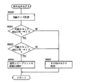
図18は図16の割込APS給紙口選択処理のフローチャートである。まず、イメージリーダIRにより検出された原稿サイズからコピーモードと倍率を考慮して用紙サイズを計算する(♯6000)。計算された用紙サイズが本体に装着されている用紙カセット80a、80bの両方に等しいサイズであれば、たとえ優先給紙口が現在プリント中の給紙口と異なっていても現在プリント中の給紙口を強制的に選択することにより、通常ジョブのプリントを中断することなく割込ジョブの画像が確定した時点で直ちに割込ジョブのプリントを開始することができる(♯6001〜♯6005)。用紙カセットと同一サイズでなければその他のAPS処理を行なう(♯6007)。以上のように、APSモードにおける原稿サイズの検出結果をもとにした給紙口選択においては、選択すべき用紙サイズの給紙口が少なくとも2つ以上存在する場合は予め設定されている給紙口選択の優先準位が必要に応じて変更される。
FIG. 18 is a flowchart of the interrupt APS paper feed port selection process of FIG. First, the paper size is calculated from the document size detected by the image reader IR in consideration of the copy mode and the magnification (# 6000). If the calculated paper size is equal to the size of both the
図19は図16の割込起動両面処理のフロ―チャートである。まず、現在プリント中の印字処理部の状態が第2面の循環サイクル中かどうか判断する(♯6500)。第2面循環サイクル中であれば、割込ジョブが片面コピーかどうか判断し(♯6501)、さらに割込ジョブへの切換が高速モードかどうか判断する(♯6503)。これは、オペレータにより予めユーザチョイス等の設定で操作パネルOPから登録しておくものとする。その設定がオンになっているときは、割込ジョブにおける片面のプリントの起動をたとえ通常ジョブの両面プリント中でもコピー用紙の裏側に不要な画像が存在してもよいという条件でできだけ速く行なうためのものである。 FIG. 19 is a flowchart of the interrupt start double-sided processing of FIG. First, it is determined whether the state of the print processing unit currently printing is in the circulation cycle of the second surface (# 6500). If it is during the second-side circulation cycle, it is determined whether or not the interrupt job is a one-sided copy (# 6501), and further, whether or not switching to the interrupt job is in the high-speed mode (# 6503). It is assumed that this is registered in advance by the operator from the operation panel OP in setting of user choice or the like. When this setting is turned on, one-sided printing in an interrupt job is started as quickly as possible under the condition that unnecessary images may be present on the back side of copy paper even during two-sided printing of a normal job. belongs to.
上記2つの条件が成立していれば、現在露光中がどうか判断する(♯6505)。露光中でなければ、図16における(♯5543〜♯5549)と同様の処理を行なう(♯6507〜♯6513)。上記2つの条件が成立していなければ、機内の用紙のすべての露光が終了するのを待ってから、割込起動処理終了の処理を行なう。第2面循環サイクルでなければ、給紙を中断するために停止要求のみをセットする(♯6517)。 If the above two conditions are satisfied, it is determined whether exposure is currently being performed (# 6505). If it is not during the exposure, the same processing as (# 5543 to # 5549) in FIG. 16 is performed (# 6507 to # 6513). If the above two conditions are not satisfied, the process of ending the interrupt activation process is performed after all the exposures of the paper in the machine are completed. If it is not the second-side circulation cycle, only a stop request is set to interrupt the sheet feeding (# 6517).
以上のように、割込ジョブにおける使用給紙口が通常ジョブにおける使用給紙口と同一である場合に、通常ジョブが両面コピーでかつ割込ジョブが片面コピーである場合は、通常ジョブにおける給紙を継続する。割込ジョブの印字データが確定した時点で、たとえ通常ジョブの印字状態が両面コピーにおける第1面を印字終了して、再給紙を行ない第2面の画像出力待ち状態であっても強制的に第2面に割込ジョブにおける画像デ―タを印字し、再給紙が終了した時点で片面コピーに切換える。 As described above, when the used paper feed port in the interrupt job is the same as the used paper feed port in the normal job, and the normal job is a two-sided copy and the interrupt job is a one-sided copy, Continue the paper. When the print data of the interrupt job is determined, even if the print status of the normal job is that the printing of the first side of the duplex copy has been completed and the sheet is re-supplied and the image output of the second side is awaited, the forced job is performed. Then, the image data of the interrupt job is printed on the second side, and when the re-feeding is completed, the mode is switched to the one-sided copy.
図20は図13のコマンド設定処理のフロ―チャートである。まず、読取るべき原稿の有無を判断する(♯5600)。原稿があれば、上述のメモリ書込動作のための処理を行なう(♯5603)。原稿がないときは読込んだ原稿をコピーモードに応じた所定回数分読出終了したかどうかの判断を行なう(♯5611)。終了していれば、メモリ書込ステートを初期化する(♯5613)。 FIG. 20 is a flowchart of the command setting process of FIG. First, it is determined whether there is a document to be read (# 5600). If there is a document, processing for the above-described memory writing operation is performed (# 5603). If there is no original, it is determined whether reading of the read original has been completed a predetermined number of times according to the copy mode (# 5611). If completed, the memory write state is initialized (# 5613).
さらに、メモリ読出処理に関しては、メモリ読出処理が終了していなければ(♯5605)、前述のメモリ読出処理のためのメモリ読出給紙およびメモリ読出伸張処理のためのサブルーチンをコールする(♯5607,♯5609)。メモリ読出処理が終了していれば、メモリ読出給紙ステートおよびメモリ読出伸張ステ―トを初期化する(♯5615、♯5617)。 Further, as for the memory reading process, if the memory reading process is not completed (# 5605), a subroutine for memory reading sheet feeding and memory reading expanding process for the above memory reading process is called (# 5607, # 5607). # 5609). If the memory reading process has been completed, the memory reading paper feeding state and the memory reading expansion state are initialized (# 5615, # 5617).
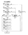
図21は図20のメモリ書込動作処理のフローチャートである。このルーチンでは、最初に書込ステートをチェックし(♯7000)、各ステート(「0」〜「3」)に応じて以下の処理を実行する。ステート「0」においては、スタートキー96のオンに呼応したスタート要求の有無をチェックする(♯700
1)。スタート要求があれば、原稿サイズ検出要求をセットし(♯7003)、現在の操作パネルOPの設定に応じて、通常読込モードであるかどうかを判断する(♯7005)。通常読込モードであれば、通常読込モードにおける書込ページ変数PWNを初期化し、メモリ書込モードにおいて、管理テーブルMT1と符号メモリ306をアクセスするための書込プリントを通常用にセットする(♯7007、♯7009)。通常読込モードでなければ、割込モードに関して前述と同様の処理を行なう(♯7013、7015)。さらにステートを1に進める(♯7011)。
FIG. 21 is a flowchart of the memory write operation process of FIG. In this routine, the write state is checked first (# 7000), and the following processing is executed according to each state ("0" to "3"). In state "0", it is checked whether there is a start request in response to turning on start key 96 (# 700).
1). If there is a start request, a document size detection request is set (# 7003), and it is determined whether the mode is the normal reading mode according to the current setting of the operation panel OP (# 7005). In the normal read mode, the write page variable PWN in the normal read mode is initialized, and in the memory write mode, the write print for accessing the management table MT1 and the
ステート「1」においては、読取コマンドをコマンド専用バッファに登録する(♯5511)。コマンド専用バッファ(Qバッファ)は、予め各コマンドごとに用意されている。各コマンドは上述の出力データセット(図13のステップ♯57)においてQバッファから通信ポートに転送される。さらにステートを「2」に進める。
In state "1", the read command is registered in the command dedicated buffer (# 5511). A command dedicated buffer (Q buffer) is prepared in advance for each command. Each command is transferred from the Q buffer to the communication port in the output data set (
ステート「2」においては、CPU6およびCPU2から読取完了リポート(読取完了A)を受取れば、原稿サイズ検出要求があるときのみ、原稿サイズ検出終了をセットする。これは前述の割込起動におけるAPS給紙口選択処理に用いられる、さらに圧縮Qバッファを登録し、ステートを「3」に進める(♯7201〜♯7209)。
In state "2", if a read completion report (read completion A) is received from
ステート「3」においては、CPUから圧縮完了レポート(圧縮完了A)を受取れば、通常読込モ―ドであれば通常読込モードにおける書込ページ数を示す変数PWNをインクリメントする。割込読込モードであれば、割込モードにおける書込ページ数を示す変数PWIをインクリメントしステートを「1」に戻す(♯7301〜♯7309)。 In the state "3", when the compression completion report (compression completion A) is received from the CPU, the variable PWN indicating the number of pages to be written in the normal read mode is incremented in the normal read mode. In the interrupt read mode, the variable PWI indicating the number of pages to be written in the interrupt mode is incremented, and the state is returned to “1” (# 7301 to # 7309).
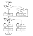
図22は図20のメモリ読出給紙処理のフローチャートである。このルーチンにおいても、最初に読出給紙ステートをチェックし(♯8000)、各ステ―ト(「0」〜「3」)に応じて以下の処理を実行する。 FIG. 22 is a flowchart of the memory read sheet feeding process of FIG. Also in this routine, the reading paper feeding state is checked first (# 8000), and the following processing is executed according to each state ("0" to "3").
ステート「0」においては、通常ジョブのプリントにおける給紙回数を示す変数PRNF、通常ジョブのプリントにおけるオペレータが設定したコピー部数(コピー枚数)を示すPRNF(M)、割込ジョブのプリントにおける給紙回数を示す変数PRIF、割込ジョブのプリントにおけるオペレータが設定したコピー部数(コピー枚数)を示す変数PRIF(M)を初期化する。変数PRNF(M)、PRIF(M)は、一群の原稿画像データを印字するための必要回数(PWNまたはPWI)だけ給紙を終了するごとに1つずつデクリメントされる。この値が「0」になれば、該当ページについての必要枚数分の給紙が終了したことになる。最後にステートを「1」に進める(♯8001〜♯8009)。 In the state “0”, a variable PRNF indicating the number of paper feeds in the printing of the normal job, PRNF (M) indicating the number of copies (number of copies) set by the operator in the printing of the normal job, and a paper feeding in the printing of the interrupt job A variable PRIF indicating the number of times and a variable PRIF (M) indicating the number of copies (the number of copies) set by the operator in the printing of the interrupt job are initialized. The variables PRNF (M) and PRIF (M) are decremented by one each time paper feeding is completed by the required number of times (PWN or PWI) for printing a group of document image data. When this value becomes “0”, it means that the required number of sheets for the corresponding page have been fed. Finally, the state is advanced to "1" (# 8001 to $ 8009).
ステート「1」においては、通常ジョブにおけるプリント中か割込ジョブにおけるプリント中かどうかを判断する(♯8101)。通常プリント中であれば、PRNF、PRNF(M)に対して、給紙回数が所定回数分終了したかどうかとオペレータが設定したコピ―部数分プリントが終了しているかの判断を行なう(♯8103、♯8105)。通常プリント中でなければ、PRIF、PRIF(M)に対して同様の処理を行なう(♯8107、♯8109)。まだすべての給紙を終了していなければ、ステートを「2」に進める(♯8111)。 In state "1", it is determined whether printing is being performed in a normal job or in an interrupt job (# 8101). If normal printing is in progress, it is determined for PRNF and PRNF (M) whether or not the number of paper feeds has been completed a predetermined number of times and whether or not printing has been completed for the number of copies set by the operator (# 8103). , $ 8105). If normal printing is not being performed, similar processing is performed on PRIF and PRIF (M) (# 8107, # 8109). If all sheet feeding has not been completed, the state is advanced to "2" (# 8111).
ステート「2」においては、前述の割込起動および復帰ルーチンにおいて、停止要求がセットされているかどうか判断する(♯8201)、セットされていなければ、1枚給紙を行なうために、プリントQバッファを登録し、ステートを「3」に進める(♯8205)。ストップ要求がセットされている場合は、新たな給紙を行なわずに給紙待ち状態にする。 In state "2", it is determined whether or not a stop request has been set in the above-described interrupt start and return routine (# 8201). If not set, the print Q buffer is used to feed one sheet. Is registered, and the state is advanced to “3” (# 8205). If the stop request has been set, the paper feed wait state is set without performing new paper feed.
ステート「3」においては、プリント要求に対して、給紙を行なったかどうかを示す給紙レポート(給紙A)を受信しているかどうかを判断する(♯83
01)。受信している場合は、通常プリント中がどうかを判断する(♯8303)。通常プリント中であれば、伸張要求バッファに通常給紙を示すデータを登録し、PRNF、PRNF(M)を更新する(実際にはPRNFを1だけインクリメントし、もしPRNFがPWNと等しくなければPRNF(M)を1だけデクリメントする)(♯8305,♯8307)。通常プリント中でなければ、割込中のプリントデータに関して前述と同様の処理を行なう(♯8309,♯8311)。最後にステ―トを「1」に戻す(♯8313)。また、給紙レポートを受信していない場合は受信するまで待ち状態とする。
In state "3", it is determined whether or not a paper feed report (paper feed A) indicating whether paper has been fed in response to the print request has been received (# 83).
01). If it has been received, it is determined whether or not normal printing is being performed (# 8303). If normal printing is in progress, data indicating normal paper feeding is registered in the decompression request buffer, and PRNF and PRNF (M) are updated (actually, PRNF is incremented by 1; if PRNF is not equal to PWN, PRNF is not used). (M) is decremented by 1) (# 8305, # 8307). If normal printing is not being performed, the same processing as described above is performed on the print data being interrupted (# 8309, # 8311). Finally, the state is returned to "1"(# 8313). If a paper feed report has not been received, the process waits until it is received.
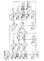
図23および図24は図20のメモリ読出伸張処理のフローチャートである。このルーチンにおいても、最初に読出伸張ステートをチェックし(♯9000)、各ステート(「0」〜「3」)に応じて以下の処理を実行する。ステート「0」においては、通常ジョブのプリントにおける伸張(露光)回数を示す変数PRNE、通常ジョブのプリントにおけるオペレータが設定したコピー部数(コピー枚数)を示す変数PRNE(M)、割込ジョブのプリントにおける伸張(露光)回数を示す変数PRIE、割込ジョブのプリントにおけるオペレータが設定したコピー部数(コピー枚数)を示す変数PRIE(M)を初期化する。変数PRNE(M)、PRIE(M)は、同一ページの画像データを伸張(露光)するごとに1つずつデクリメントされ、この値が「0」になれば、該当ページについての必要枚数分の露光が終了したことになる。最後にステートを
「1」に進める(♯9001〜♯9009)。
FIG. 23 and FIG. 24 are flowcharts of the memory read expansion processing of FIG. Also in this routine, the read expansion state is checked first (# 9000), and the following processing is executed according to each state ("0" to "3"). In the state “0”, a variable PRNE indicating the number of times of expansion (exposure) in printing a normal job, a variable PRNE (M) indicating the number of copies (the number of copies) set by an operator in printing a normal job, and printing an interrupt job And a variable PRIE (M) indicating the number of copies (number of copies) set by the operator in the printing of the interrupt job. The variables PRNE (M) and PRIE (M) are decremented by one each time the image data of the same page is decompressed (exposure). If this value becomes “0”, the required number of exposures for the corresponding page is obtained. Has ended. Finally, the state is advanced to "1"(# 9001 to $ 9009).
ステート「1」においては、通常ジョブにおけるプリント中か割込ジョブにおけるプリント状態かを判断する(♯9101)。通常プリント中であれば、PRNE、PRNE(M)に対して伸張回数が所定回数分終了したかどうかと、オペレータが設定したコピー部数分の伸張が終了しているかの判断を行なう(♯9103、♯9105)。通常プリント中でなければ、PRIE、PRIE(M)に対して同様の処理を行ない(♯9107、♯9109)、またすべての伸張を終了していなければ、ステートを「2」に進める(♯9111)。 In state "1", it is determined whether printing is being performed in a normal job or in an interrupt job (# 9101). During normal printing, it is determined whether the number of expansions for PRNE and PRNE (M) has been completed a predetermined number of times, and whether expansion for the number of copies set by the operator has been completed (# 9103, $ 9105). If normal printing is not being performed, similar processing is performed for PRIE and PRIE (M) (# 9107, # 9109). If all decompression has not been completed, the state is advanced to "2" (# 9111). ).
ステート「2」においては、前述のメモリ読出給紙でセットされた伸張要求バッファにデータが存在するかどうか判断する(♯9201)。存在すればそのバッファデータが通常モードにおける給紙か、割込モ―ドにおける給紙かどうかを判断する(♯9203)。通常モードであれば、現在のプリントモードが本当に通常プリントモードであるかどうかを判断する(♯9205)。もし通常プリントモードでなければ、通常ジョブと割込ジョブにおける使用給紙口が同一で給紙した時点は通常のモードであったが、露光しようとしたときは既に割込に切換わったと判断し、通常モードの給紙変数PRNF、PRNF(M)に関しては、前述のメモリ読出給紙のステップ♯8307で実行された処理とは逆の処理(PRNFを1だけデクリメントし、もし0になれば、PRNF(M)を1だけインクリメントする)を行なう(♯9207)。 In state "2", it is determined whether or not data exists in the decompression request buffer set by the above-described memory read sheet feeding (# 9201). If the buffer data exists, it is determined whether the buffer data is a paper feed in the normal mode or a paper feed in the interrupt mode (# 9203). If it is the normal mode, it is determined whether the current print mode is really the normal print mode (# 9205). If it is not the normal print mode, it is determined that the normal paper feeding mode is used at the time of feeding the same paper feed port in the normal job and the interrupt job, but it has been switched to the interrupt mode when trying to expose. Regarding the paper feed variables PRNF and PRNF (M) in the normal mode, the reverse process (the PRNF is decremented by 1 if the process is executed at step # 8307 of the above-mentioned memory read paper feed, and if it becomes 0, PRNF (M) is incremented by 1) (# 9207).
さらに、通常のコピーモードが両面コピーモードの場合は、第2面循環サイクル中に割込プリントに切換わったと判断できるので、このときはさらにステップ♯8307が実行された処理とは逆の処理をもう一度行なう。 Further, when the normal copy mode is the duplex copy mode, it can be determined that the mode has been switched to the interrupt print during the second-side circulation cycle. In this case, the process reverse to the process in which step # 8307 is executed is further performed. Do it again.
この処理によって、割込ジョブで強制的に第2面印字を行なったページに関しては、通常ジョブに復帰したときに、補正してもう一度プリントすることができる。さらに割込モードの給紙変数PRIF、PRIF(M)に関しても前述のメモリ読出給紙のステップ♯8311と同様の更新処理を行なう(♯9209)。 With this process, the page on which the second side printing has been forcibly performed in the interrupt job can be corrected and printed again when returning to the normal job. Further, update processing similar to that in step # 8311 of the above-described memory read sheet feeding is performed for sheet feeding variables PRIF and PRIF (M) in the interrupt mode (# 9209).
ステップ♯9205で通常プリントモードであった場合は上記補正処理は必要ない。また、ステップ♯9203で読出したデータが割込モードである場合は、現在のプリントモードが本当に割込プリントモードであるかどうかを判断する(♯9211)。もし割込プリントモードでなければ、割込モードから通常モードのプリントに切換わったと判断し、割込モードの給紙に関して、前述と同様の戻し補正(♯9213)、通常モードの給紙に関して前述と同様の更新補正を行なう(♯9215)。さらに、伸張起動のために伸張Qバッファを登録し、ステートを「3」に進める(♯9219)。
If it is the normal print mode in step # 9205, the above correction processing is not necessary. If the data read in
ステート「3」においては、プリント完了レポート(プリント完了A)を受信しているかどうかを判断する(♯9301)。受信していれば、通常プリントモードかどうか判断する(♯9303)。通常プリントモードであれば、PRNE、PRNE(M)を更新する。実際にはPRNEを1だけインクリメントし、もしPRNEがPWNと等しくなければPRNE(M)を1だけデクリメントする(♯9305)。通常プリントモ―ドでなければ、割込の伸張データに関して前述と同様の処理を行なう。最後にステートを「1」に戻す(♯9309)。プリント完了レポートを受信していない場合は、受信するまで待ち状態となる。 In state "3", it is determined whether a print completion report (print completion A) has been received (# 9301). If received, it is determined whether the mode is the normal print mode (# 9303). If the print mode is the normal print mode, PRNE and PRNE (M) are updated. Actually, PRNE is incremented by one, and if PRNE is not equal to PWN, PRNE (M) is decremented by one (# 9305). If not in the normal print mode, the same processing as described above is performed on the decompressed data of the interrupt. Finally, the state is returned to "1" (# 9309). If the print completion report has not been received, the process is in a waiting state until the report is received.
さらに、通常のコピーモードが両面コピーモードの場合は、第2面循環サイクル中に割込プリントに切換わったと判断できるので、このときはさらにステップ♯8307で実行された処理とは逆の処理をもう一度行なう。この処理によって、割込ジョブで強制的に第2面印字を行なったページに関しては通常ジョブに復帰したとき補正してもう一度プリントすることができる。 Further, if the normal copy mode is the duplex copy mode, it can be determined that the print mode has been switched to the interrupt print during the second-side circulation cycle. In this case, the process opposite to the process executed in step # 8307 is further performed. Do it again. With this process, the page on which the second page has been forcibly printed in the interrupt job can be corrected and returned to the normal job and printed again.
次に図15の♯5505で示した割込プリント待ち判断ルーチンについて図25を参照して説明する。ステップ♯5900では両面コピーかどうかの判断およびステップ♯5903ではNin1コピーかどうかの判断を行なう。どちらか一方でも条件が成立していれば、ステップ♯5909で原稿読込終了かどうかの判断を行なう。本実施例では、原稿を最後のページから読込むため、両面コピーまたはNin1コピーではすべての原稿を読込むまで原稿枚数がわからない。したがって、最初に読取った原稿の印字面および位置が確定しないため、すべての原稿読込終了するまでは割込プリント待ち状態にする(♯5911)。
Next, the interrupt print wait determination routine indicated by # 5505 in FIG. 15 will be described with reference to FIG. At
次にステップ♯5905では、割込ジョブの給紙口がペーパーエンプティかどうかを判断する。もしペーパーエンプティであれば、ステップ♯5911で同様の処理を行なう。ステップ♯5905でペーパーエンプティでない場合には、割込ジョブのプリントが可能であるので、割込プリント待ち状態を解除する。
Next, in
図26はCPU5が行なうフィニッシング処理としてのバインドモードの動作内容を示すフローチャートである。図26を参照して、バインドモードのコピーを開始すると(♯501)、バインドカバーを1枚収納トレイにセットする(♯502)。次に、メモリされた画像データを1ページ分ずつ取出して複写する(♯503,♯504,♯505)。1セットの複写が終了して(♯506)、用紙が収納トレイに収納されるとバインド処理を開始する(♯507)。
FIG. 26 is a flowchart showing the operation contents of the bind mode as finishing processing performed by the
バインドタイマを監視して、バインドが完了していなかった場合は、登録された他の予約ジョブである、メモリされた画像データの中にバインドジョブ以外のものがあればその画像データの複写を行なって、別の排紙トレイに排出する(♯508,♯511)。バインドタイマが終了すると、バインドしている用紙を排出する(♯508,♯510)。バインドモードがマルチコピーの場合は、マルチ分のコピーが完了していなければ(♯510でNO)、再び♯502からプログラムが開始する。 If the bind timer is not completed and the bind timer is not completed, if there is any other reserved job, that is, if the stored image data is other than the bind job, the image data is copied. Then, the paper is discharged to another paper discharge tray (# 508, # 511). When the bind timer expires, the bound paper is discharged (# 508, # 510). When the bind mode is the multi-copy, if the copy for the multi is not completed (NO in # 510), the program starts again from # 502.
図27は図26において♯507で示したバインド処理の内容を示すフローチャートである。バインド処理が呼ばれると、バインド加熱板を加熱してバインドを開始する(♯521)。バインドを開始したときに、バインドタイマをスタートさせる(♯522)。このバインドタイマは割込処理で減算される。 FIG. 27 is a flowchart showing the contents of the bind process indicated by # 507 in FIG. When the binding process is called, the binding heating plate is heated to start binding (# 521). When the binding is started, the binding timer is started (# 522). This bind timer is decremented in the interrupt processing.
次にこの発明の他の実施形態について説明する。他の実施形態においては、複写機2はパソコンや、FAXコントーラに接続され、イメージリーダIR以外からの入力情報をページプリンタPRTでプリントアウトする。この実施形態では、複写機2の用紙カセットは図1のように2つではなく、後に説明するように4つ設けられている。また、バインド部は設けられていない。
Next, another embodiment of the present invention will be described. In another embodiment, the copying
図28はこの実施形態における複写機2の全体構成を示すブロック図であり、先の実施形態と対応する部分には対応する参照符号等が記載されている。図28を参照して、この実施形態における複写機2は外部に設けられたパソコン51や、FAXコントローラ50や、イメージリーダIRに接続され、それらをコントロ―ルするマルチジョブコントローラ208を含む。マルチジョブコントローラ208は先の実施形態におけるCPU5の作動と同様の作動を行なう。マルチジョブコントローラ208はメモリユニット部30に接続され、メモリユニット部30はバッファメモリ206やビットマップメモリ207を有する。マルチジョブコントローラ208はさらに、ページプリンタPRTに接続されており、ページプリンタPRTはプリンタコントローラ205と印字処理部40とを含む。
FIG. 28 is a block diagram showing the entire configuration of the copying
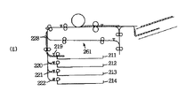
図29はこの実施形態での用紙搬送機構を説明するための概略図である。図29を参照して、複写機2は第1給紙カセット〜第4給紙カセット211〜214の4つの給紙カセットと、両面機能を持つ両面ユニット247と、各ユーザごとに印字出力を仕分けできるメールボックス248とを含む。
FIG. 29 is a schematic diagram for explaining the sheet transport mechanism in this embodiment. Referring to FIG. 29,
次に図29を参照して複写機2の用紙搬送動作について説明する。まず第1給紙カセット211から片面印字を行ない、第1メールトレイ243に印字された用紙を排出するまでの動作を説明する。給紙ローラユニット215を回転させ、第1給紙カセット211から用紙を1枚給紙する。ペーパセンサ219にて用紙の先端を検出し、所定時間後、用紙が搬送ローラ226にて搬送されている状態のときに、給紙ローラユニット215を停止する。
Next, the paper transport operation of the copying
搬送ローラ226にて搬送される用紙は、中間ローラ227を経てレジストローラ229で印字タイミングと同期され、感光体ドラム71へ搬送される。
The paper conveyed by the
転写チャージャ75にて用紙上に画像が転写された後、定着ローラ対84にて画像が定着され、再給紙ユニット600に用紙が搬送される。再給紙ユニット600内では、排出ゲート232をオンし、用紙を排出方向へ搬送する。メールボックス248内では、用紙を第1メールトレイ243へ排出するために排出ゲート240をオンする。
After the image is transferred onto the sheet by the
次に第4カセット214から2枚の用紙に両面印字を行ない、第4メールトレイ246に排出する場合の動作を説明する。給紙ローラユニット218を回転させ、第4給紙カセット214から用紙を1枚給紙する。ペーパセンサ222にて用紙の先端を検出したら、所定時間後用紙が搬送ローラ223にて搬送されている状態のときに給紙ローラユニット218を停止する。さらに給紙された用紙がペーパセンサ222を通過したら所定時間(1枚目給紙と距離を一定にするようにして)経過後再度、給紙ローラユニット218を回転させ、第4給紙カセット214から2枚目の用紙を給紙する。ペ―パセンサ222にて用紙の先端を検出したら、所定時間後用紙が搬送ローラ226にて搬送されている状態のときに給紙ローラユニット218を停止する。
Next, an operation in a case where two-sided printing is performed on two sheets from the
給紙された2枚の用紙は、搬送ローラ224〜226、中間ローラ227を経て上記と同様に感光体ドラム71に送られ、そこで画像が形成され定着部30にて定着される。その後、再給紙ユニット600内の排出ゲート232をオフし、用紙は搬送ローラ233で再給紙ユニット600内に搬送される。そして、スイッチバックローラ234を正逆転させ本体内へ用紙を再度送り込む。搬送ローラ235〜239、中間ローラ227、レジストローラ229にて用紙は再度感光体ドラム71へ搬送される。この感光体ドラム71では、裏面に画像が形成され、その後定着ローラ対84にて定着され、再給紙ユニット600に搬送される。再給紙ユニット600内では、排出ゲート232をオンし、用紙を排出方向へ搬送する。メールボックス248内では、用紙を第4メールトレイ246へ排出するために排出ゲート240〜242をオフする。
The two fed sheets are sent to the
用紙を再給紙するための再給紙経路261は上記した搬送ローラ235〜239を含み、再給紙ユニット600から搬送された用紙を一定の速度で搬送するもので、中間トレイのようなストック手段は設けられていない。再給紙経路261の出口に再給紙口が設けられている。また、上記の複写機2には各給紙カセットに収納された用紙のサイズおよび方向を記憶するメモリ(不図示)が設けられている。各カセットの用紙サイズ、方向の入力はたとえばディップスイッチによってなされる。また、メモリを設けず、各給紙口にマイクロスイッチを設け、カセット内に収納された用紙サイズおよび方向を検知するようにしてもよい。なお、第1給紙カセットの出口を給紙口1、第2給紙カセットの出口を給紙口2、第3給紙カセットの出口を給紙口3および第4給紙カセットの出口を給紙口4とする。
A
次に図28に示したプリンタコントローラ205と印字処理部40との間の通信について説明する。複写機2内のプリンタコントローラ205と印字処理部40とは相互にデータおよびコマンドを送受信することによって給紙カセットからの用紙の搬送を制御する。
Next, communication between the printer controller 205 and the
プリンタコントローラ205がプリントコマンドを送信すると、印字処理部40は必ず給紙レポートを送信する。この給紙レポートには次の3種類がある。
(1) 給紙レポート(給紙したときに送信される)
(2) 給紙レポート(不可)(エラーまたは、ペーパエンプティなどにより給紙できないときに送信される)
(3) 給紙レポート(不可:再給紙優先)(再給紙口優先のため給紙できないときに送信される)プリンタコントローラ205はプリントコマンド送信後、給紙レポートを受信するのを待ち、給紙レポートを受信したら次のプリントコマンドを発生できる。なおここでさきにプリンタコマンドした用紙に関する排出レポ―トと今回のプリントコマンドの前後関係は問わない。
When the printer controller 205 sends a print command, the
(1) Paper feed report (sent when paper is fed)
(2) Paper feed report (impossible) (Sent when paper cannot be fed due to an error or paper empty, etc.)
(3) Paper feed report (impossible: refeed priority) (transmitted when paper cannot be fed due to priority of the refeed slot) After transmitting the print command, the printer controller 205 When the paper feed report is received, the next print command can be issued. It should be noted that there is no limitation on the relationship between the discharge report relating to the sheet previously subjected to the printer command and the current print command.
以下にこれから説明するプリンタコントロ―ラ205と印字処理部40から送信されるデータの具体的な内容について説明する。
Hereinafter, specific contents of data transmitted from the printer controller 205 and the
プリントコマンド:印字動作要求を行なう給紙レポート:給紙したこと伝える給紙レポート(不可):給紙できないことを伝える給紙レポート(不可:再給紙優先):給紙できないことを伝える(再給紙優先)排出レポート:機外へ排出したことを伝える排出レポート(再給紙):両面印字のとき、片面を印字して再給紙口へ排出したことを伝える給紙口設定:カセットナンバー:給紙するカセットを設定する給紙設定(再給紙):給紙するカセットを再給紙口に設定する両面設定:印字後の用紙を再給紙口へ搬送指定する排出設定、片面設定:印字後の用紙を機外へ排出する以下、各場合について個別に説明する。 Print command: Paper feed report for requesting print operation: Paper feed report that reports that paper has been fed (impossible): Paper feed report that reports that paper cannot be fed (impossible: Priority for refeeding): Paper feed priority) Ejection report: Ejection report that reports that the paper has been ejected outside the machine (re-feeding): In duplex printing, one-sided printing and paper ejection port setting that indicates that the paper has been ejected to the paper re-emission slot: Cassette number : Set the cassette to feed paper. Feed setting (re-feed): Set the cassette to feed paper to the re-feed slot. Duplex setting: Eject setting to specify the transport of printed paper to the re-feed slot, single-sided setting : Discharge paper after printing outside the machine. Each case will be individually described below.
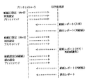
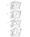
まず、1枚の用紙に片面印字をする場合について説明する。この場合は、図30(A)に示すようなデータが双方から出力される。まずプリンタコントロ―ラ205から給紙口1指定および片面設定でプリントコマンドを発生する。給紙ローラユニット215を回転させ、第1給紙カセット211から用紙を1枚給紙する。このとき印字処理部40は給紙レポートを送信する。その後の動作は先に図29で複写機の構成を説明した場合と同様であるのでその説明は省略する。給紙された用紙に作像および印字が行なわれ、定着排出センサ231を通過したときに印字処理部40は排出レポートを送信する。
First, a case where one-sided printing is performed on one sheet will be described. In this case, data as shown in FIG. First, a print command is generated from the printer controller 205 with the designation of the
次に2枚の用紙に印字する場合の例について図30(B)を参照して説明する。給紙口1から片面指定でプリンタコントローラ205がプリントコマンドを発生し、これに応答して印字処理部40が給紙レポート(1枚目)を送信するまでは図30(A)の場合と同様である。次にプリンタコントローラ205は給紙レポ―トを受信したら2枚目のプリントコマンドを発生する。これに応答して印字処理部40は2枚目の給紙レポ―トを送信する。それぞれの用紙は順に感光体ドラム71へ搬送され印字が行なわれる。印字が完了した用紙が機外に搬出された時点で1枚目、2枚目の順に排出レポ―トが印字処理部40から送信される。
Next, an example of printing on two sheets will be described with reference to FIG. The printer controller 205 generates a print command by specifying one side from the
次にカセット内の用紙がなくなったペーパエンプティの状態で印字が禁止される場合について図30(C)を参照して説明する。まずカセット給紙口および片面設定が行なわれてプリントコマンドが発生されるまでは先の例と同様である。この場合にはプリントコマンドに応答して印字処理部40が給紙ができない旨を伝える給紙レポート(不可)を送信する。
Next, a case where printing is prohibited in a paper empty state in which the paper in the cassette is exhausted will be described with reference to FIG. The process is the same as that of the previous example until the print command is generated after the cassette sheet feeding port and one side are set. In this case, in response to the print command, the
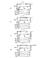
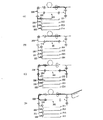
次に両面印字について説明する。図31
(A)はこの場合の通信内容を示す図である。給紙口2から両面指定でプリンタコントローラ205が片面用のプリントコマンドを発生する。給紙ローラユニット216を回転させ、第2給紙カセット212から用紙を1枚給紙する。このとき印字処理部40は給紙レポート(片面)を送信する。給紙された用紙に印字が行なわれ、定着排出センサ231を通過したときに印字処理部40が排出レポート(再給紙)を送信する。そして用紙が感光体ドラム71へ搬送され、裏面に印字される。両面とも印字された用紙が機外に排出された時点で排出レポートが印字処理部40から出力される。
Next, two-sided printing will be described. FIG.
(A) is a diagram showing communication contents in this case. The printer controller 205 generates a print command for one side by specifying both sides from the
次に2枚の用紙の両面に印字を行なう場合について図31(B)を参照して説明する。1枚目および2枚目の両方について給紙レポート(片面)がそれぞれ出力されるまでは図31(A)で説明した場合と同様である。その後1枚目についてプリンタコントローラ205から再給紙設定、排出設定が行なわれてプリントコマンドが出力される。これに応答して印字処理部40からは1枚目および2枚目の用紙について再給紙口へ用紙が排出された旨の信号がおよび1枚目の用紙についての給紙レポート(再給紙)が出力される。これに応答してプリンタコントローラ205では2枚目の用紙の裏面に対するプリントコマンドを送信する。1枚目および2枚目の用紙が感光体ドラム71へ搬送され、それぞれの裏面に印字が行なわれる。両面とも印字された用紙が機外に排出された時点で1枚目および2枚目の順に排出レポ―トが印字処理部40から送信される。
Next, a case where printing is performed on both sides of two sheets will be described with reference to FIG. The process is the same as that described with reference to FIG. 31A until the paper feed report (one side) is output for both the first and second sheets. Thereafter, for the first sheet, re-feed setting and discharge setting are performed from the printer controller 205, and a print command is output. In response to this, the
次に、用紙2枚の両面に印字する他の例について図32を参照して説明する。この場合における図31との相違点は再給紙された1枚目の用紙に対するプリントコマンドの送信が排出レポート(再給紙)を受信した後になっている点である。それ以外の点については図31(B)の場合と同様であるのでその詳細な説明は省略する。 Next, another example of printing on both sides of two sheets of paper will be described with reference to FIG. The difference from FIG. 31 in this case is that the transmission of the print command for the first sheet re-fed is after receiving the discharge report (re-feed). The other points are the same as those in the case of FIG. 31 (B), and the detailed description is omitted.
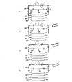
次に2枚の用紙の両面に印字する場合のさらに他の例について図33を参照して説明する。 この場合に図31(B)に示した例との相違点は、2枚目のプリントコマンド(片面)を送信するタイミングが排出レポート(再給紙)を送信した後になっている点すなわち、コマンド発生が遅れている点である。 Next, still another example of printing on both sides of two sheets will be described with reference to FIG. In this case, the difference from the example shown in FIG. 31B is that the timing of transmitting the second print command (one side) is after transmitting the discharge report (re-feeding), that is, the command The point is that the generation is delayed.
図33を参照して、カセット給紙口2から両面指定でプリンタコントローラ1Aがプリントコマンドを発生する。給紙ローラユニット216を回転させ、第2給紙カセット212から用紙を1枚給紙する。このとき、印字処理部40は給紙レポート(片面)を送信する。
Referring to FIG. 33, printer controller 1A generates a print command by specifying both sides from cassette
上記給紙された用紙に印字が行なわれ、定着排出センサ231を通過したときに印字処理部40は排出レポート(再給紙)を送信する。その後、プリンタコントローラ205は2枚目の印字準備ができた時点でカセット給紙口2から両面指定でプリントコマンドを発生する。給紙ローラユニット216を回転させ、第2給紙カセット212から用紙(2枚目)を1枚給紙する。このとき印字処理部40は給紙レポート(片面)を送信する。
Printing is performed on the fed paper, and when the paper passes the fixing
2枚目の給紙レポート(片面)を受信した後、プリンタコントローラ205は再給紙口を指定して、排出設定でプリントコマンド(1枚目の裏面用)を発生する。再給紙口に搬送された第1枚目の用紙が、水平搬送路突入ペーパセンサ236に到達していれば(または到達した時点で)、再給紙口の給紙レポートおよび排出レポート(1枚目)を発生する。そして、第1枚目の用紙は搬送ローラ237〜239,227,229にて感光体ドラム71へ搬送され、裏面に印字される。
After receiving the second sheet feed report (one side), the printer controller 205 designates a sheet re-feeding port and generates a print command (for the back side of the first sheet) with discharge setting. If the first sheet conveyed to the paper re-feeding port has reached (or at the time of reaching) the paper sensor entering the horizontal conveyance path, the paper feeding report and the discharge report (one sheet) of the paper re-feeding port. Eyes). Then, the first sheet is transported to the
第1枚目の再給紙の給紙レポートが送信された後、プリンタコントローラ205は再給紙口を指定して、排出設定でプリントコマンド(2枚目の裏面用)を発生する。再給紙口に搬送された第2枚目の用紙が水平搬送路突入ペーパセンサ36に到達していれば(または到達した時点で)、再給紙口の給紙レポート(2枚目)を発生する。 After the report of the first sheet re-feeding is transmitted, the printer controller 205 designates a sheet re-feeding port and generates a print command (for the back side of the second sheet) in discharge setting. If the second sheet conveyed to the paper re-feeding port has reached (or at the time of arrival) the paper sensor 36 entering the horizontal conveyance path, a paper feeding report (second sheet) of the paper re-feeding port is generated. I do.
そして、第2枚目の用紙は搬送ローラ237〜239,227,229にて感光体ドラム71へ搬送され、裏面に印字される。両面とも印字された用紙が機外に排出された時点で、1枚目、2枚目の順に排出レポートが印字処理部40から送信される。
Then, the second sheet is transported to the
次に2枚の用紙の両面に印字する場合のさらに他の例について説明する。この例は2枚目のプリントコマンドが遅くなり、再給紙から用紙と衝突するため2枚目の給紙をキャンセルする場合に相当する。 Next, still another example of printing on both sides of two sheets will be described. This example corresponds to a case where the second print command is delayed and the second paper feed is canceled because the second print command collides with the paper.
図34を参照して、給紙口2から両面指定でプリンタコントローラ205がプリントコマンドを発生する。給紙ローラユニット216を回転させ、第2給紙カセット212から用紙を1枚給紙する。このとき、印字処理部40が給紙レポートを送信する。給紙された用紙に印字が行なわれ、定着排出センサ231を通過したときに印字処理部40が排出レポート(再給紙)を送信する。その後、プリンタコントローラ205は2枚目の印字準備ができた時点でカセット給紙口2から両面指定でプリントコマンドを発生する。
Referring to FIG. 34, printer controller 205 generates a print command by specifying both sides from
このとき、カセット給紙口2から中間ローラ228までの距離と、既に片面が印字され、再給紙口を搬送されている用紙と中間ローラ228までの距離を比較する。この場合はそのまま給紙すると用紙同士が衝突するため、印字処理部40が給紙レポート(不可:再給紙優先)を送信する。
At this time, the distance from the cassette
プリンタコントローラ205は給紙レポート(不可:再給紙優先)を受信したため、給紙口2から給紙できなくなったことが判断できる。そこでプリンタコントローラ205は再給紙口指定、排出設定でプリントコマンド(1枚目の裏面用)を発生する。再給紙口に搬送された第1枚目の用紙が水平搬送路突入ペーパセンサ236に到達していれば(または到達した時点で)再給紙口の給紙レポート(1枚目)を発生する。その後裏面を印字し、用紙は機外に排出され、排出レポートが印字処理部40から送信される。
Since the printer controller 205 has received the paper feed report (impossible: refeed priority), it can determine that paper cannot be fed from the
なお、この発明に係る複写機においては以上のような制御を行なっているが、これは再給紙経路261中の用紙はその搬送を止めることができないため、給紙部からの給紙を中断し、再給紙経路261からの給紙を優先して行なっているためである。したがって、再給紙トレイ等のストック手段を再給紙経路261中に設けた複写機では上記のような制御は不要である。
The above-described control is performed in the copying machine according to the present invention. However, since the conveyance of the paper in the
なお、この再給紙経路261中の用紙の位置は一義的に決まるものではなく、プリンタコントローラ205の事情によって変化する。すなわち、プリンタコントローラ205は、記録するべきデータをビットマップメモリに展開した後に印字処理部40に給紙コマンドを送信する。しかしながら、たとえば同じA4サイズのデータであっても、データが文字データであるか画像データであるかによってこの展開時間は異なる(なお、この実施例に係るプリンタコントローラ205は、使用可能な最大サイズの用紙2頁分のメモリを備えているものとする)。したがって、次の用紙に印字されるデータを展開するのにかかる時間によって再給紙経路61中の用紙(片面プリント済のもの)の位置は変化する。また、次に記録されるべき用紙へのプリント指令がホストコンピュータから送信されるタイミングによっても再給紙経路261中の用紙の位置は変化する。
Note that the position of the sheet in the
上記の図33と図34の異なる点は、1枚目の用紙が再給紙口のどの位置にあるかによってカセットからの給紙を行なうか否かという点である。そこで、以下に給紙するか、給紙を不可にするかをどのように判断するかを説明する。 The difference between FIG. 33 and FIG. 34 lies in whether or not the sheet is fed from the cassette depending on the position of the first sheet in the re-feeding port. Therefore, the following describes how to determine whether to feed paper or not to feed paper.
給紙口1に設けられた給紙ローラ215、給紙口2の出口に設けられた給紙ローラ216、給紙口3に設けられた給紙ローラ217、給紙口4に設けられた給紙ローラ218および給紙口X(X=1〜4)に設けられた給紙ローラ215〜218から中間ローラ227までの距離をそれぞれLf1,Lf2,Lf3,Lf4およびLfXとする。
A
定着排出センサ231から再給紙経路261を通って中間ローラセンサ228までの距離をLdpとし、最適な用紙間隔をLinvとする。
The distance from the fixing
第1〜第4給紙カセットおよび第X給紙カセット(X=1〜4)に搭載されているペーパサイズをそれぞれPSf1〜PSf4およびPSfxとする。 The paper sizes mounted on the first to fourth sheet cassettes and the Xth sheet cassette (X = 1 to 4) are denoted by PSf1 to PSf4 and PSfx, respectively.
排出レポート(再給紙)が発生してからの経過時間をTMdp1とし(なお、複写機1には排出レポートを発生した数のタイマが設けられているとする)、システム速度をSpとする。
It is assumed that the elapsed time since the generation of the discharge report (re-feeding) is TMdp1 (note that the copying
両面印字を行なうとき、片面の印字が終了し、排出レポートが発生した際タイマのカウントをスタ―トさせる。次に、カセット給紙口Xからのプリントコマンドが発生したとき、以下の演算を行なう。 When double-sided printing is performed, the count of the timer is started when printing on one side is completed and a discharge report is generated. Next, when a print command is issued from the cassette sheet feeding port X, the following calculation is performed.
X1=Ldp−LfX−Linv−PSfx−TMdp1×Sp上記X1の値が0未満であればカセット給紙口Xのプリントコマンドを禁止し、給紙レポート(不可:再給紙優先)を送信する。これは用紙の衝突が起こる可能性があるためである。 X1 = Ldp-LfX-Linv-PSfx-TMdp1 * Sp If the value of X1 is less than 0, the print command of the cassette paper feed port X is prohibited, and a paper feed report (impossible: refeed priority) is transmitted. This is because a paper collision may occur.
計算値X1が0以上であればカセット給紙口Xのプリントコマンドを許可し、給紙動作を行ない、給紙レポートを送信する。このタイミングで給紙していれば正常に印字できるためである。なお、上記処理の具体的フローチャートは後に説明する。 If the calculated value X1 is 0 or more, the print command of the cassette paper feed port X is permitted, a paper feed operation is performed, and a paper feed report is transmitted. This is because printing can be performed normally if paper is fed at this timing. A specific flowchart of the above processing will be described later.
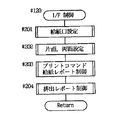
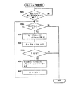
次に印字処理部40の動作について説明する。図35は印字処理部40の制御ルーチンを示すフロ―チャートである。図35を参照して、電源がオンされると、♯110にて各種の初期化の処理を行なう。♯120では、プリンタコントローラからのコマンドを受信、解析したり、プリンタコントローラ205に印字処理部制御のレポートを送信したりするインタフェース(I/F)制御を行なう。♯130では、用紙の搬送状況を検出し、搬送動作を制御する用紙搬送制御の処理を行なう。♯140では作像その他の処理を行なう。
Next, the operation of the
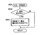
図36は図35の♯120に示すI/F制御のサブルーチンを示すフローチャートである。まずどの給紙口を設定するかの処理を行ない(♯201)、片面プリントか両面プリントかの設定を行なう(♯202)。プリントコマンドの受信や、給紙レポートの送受信の制御を行ない(♯203)、排出レポート送信のための制御を行なう(♯204)。 FIG. 36 is a flowchart showing a subroutine of I / F control shown at # 120 in FIG. First, a process for determining which paper feed port is to be set is performed (# 201), and setting for single-sided printing or double-sided printing is performed (# 202). It controls the reception of the print command and the transmission and reception of the paper feed report (# 203), and the control for sending the discharge report (# 204).
図37は図36の♯201の給紙口設定の処理を示すサブルーチンの内容を表わすフローチャートである。まずプリンタコントローラ205からの、給紙するカセットの設定を示す給紙口設定コマンドを受信したかどうかの判断を行ない、受信した場合には受信したコマンドに従って給紙口を設定する(♯2010でYes,♯2011)。 FIG. 37 is a flowchart showing the contents of a subroutine showing the process of setting the paper feed port at # 201 in FIG. First, it is determined whether or not a paper feed port setting command indicating the setting of a cassette to be fed from the printer controller 205 has been received. If the command has been received, the paper feed port is set according to the received command (Yes in # 2010). , $ 2011).
図38は図36の♯202の片面・両面設定の処理を示すサブルーチンである。プリンタコントロ―ラ205からの、印字後の用紙を機外に排出するか再給紙口搬送指定するかを示す片面設定コマンドや両面設定コマンドを受信したかどうかの判断を行ない(♯2020)、受信した場合には受信したコマンドに従って機外排出、再給紙搬送を決定する(♯2021)。 FIG. 38 is a subroutine showing a process for setting one side / two sides of # 202 in FIG. A determination is made as to whether a single-sided setting command or a double-sided setting command indicating whether the printed paper is to be discharged out of the apparatus or the re-feeding port is designated from the printer controller 205 has been received (# 2020). If it has been received, external discharge and re-feed conveyance are determined according to the received command (# 2021).
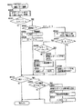
図39は、図36の♯203に示すプリントコマンド・給紙レポート制御の処理を示すサブルーチンである。プリンタコントローラ205に対して排出レポートを送信した後のタイマカウント制御を行なう(♯2030)。次にプリントコマンドの受信を行なったかどうかの判断を行ない(♯2031)、受信した場合には給紙口の設定がカセットからの給紙か再給紙口からの給紙かを判断する(♯2033)。給紙口からの給紙の場合には再給紙口から給紙される用紙に対してプリントを行なうときに立てるフラグF FEEDを1に設定する(♯2034)。反転搬送路247内に内蔵されている枚数のカウンタCTをCT−1にデクリメントする(♯2035)。 FIG. 39 is a subroutine showing a print command / paper feed report control process shown in # 203 of FIG. Timer count control after transmitting the discharge report to printer controller 205 is performed (# 2030). Next, it is determined whether or not a print command has been received (# 2031). If the print command has been received, it is determined whether the paper supply port setting is paper supply from a cassette or paper supply from a re-paper supply port (# 203). 2033). In the case of paper feeding from the paper feeding port, the flag F FEED which is set when printing is performed on the paper fed from the paper feeding port is set to 1 (# 2034). The counter CT of the number of sheets incorporated in the reverse conveyance path 247 is decremented to CT-1 (# 2035).
♯2032にて、F FEEDが1であるとき、すなわち再給紙口からの用紙に対するプリントの場合には、両面ユニット247で反転された片面プリント後の用紙先端が水平搬送路突入ペーパセンサ236をオンしたかどうかを判別し(♯2053)、オンしたタイミングで、プリンタコントローラ1Aに再給紙優先の給紙レポートを送信する(♯2054)。その後用紙をプリント部に再給紙するための制御を行ない(♯2055)、F FEEDを0にリセットする(♯2056)。
In
一方、♯2033で給紙口の設定がカセットからの給紙であると判断されると、先に説明した“X1”の値を計算する(♯2036)。“X1”の値が0未満、すなわち、♯2037にてNoと判断されると、そのまま給紙カセットから給紙すると給紙されてくる用紙と衝突するおそれがあるので、プリンタコントローラ205に対して再給紙優先の給紙レポートを送信するとともに、プリントコマンドの実行を禁止する(♯2038)。 On the other hand, if it is determined in # 2033 that the sheet feeding port is set to feed from a cassette, the value of "X1" described above is calculated (# 2036). If the value of “X1” is less than 0, that is, if No is determined in # 2037, if the sheet is fed from the sheet cassette as it is, there is a possibility that the sheet will collide with the sheet fed. A paper feed report with priority on re-feeding is transmitted, and execution of the print command is prohibited (# 2038).
♯2037にて“X1”の値が0以上であると判断されると、給紙カセットから給紙しても再給紙用紙と衝突するおそれがないので、設定されているカセットにペーパエンプティなどのエラーがないことを確認後(♯2039)、給紙カセットから給紙動作を開始させ(♯2050)、プリンタコントローラ1Aに給紙レポートの送信を行なう(♯2051)。この場合に給紙カセットにエラーがあるときは(♯2039でYES)、給紙不可の給紙レポートを送信する(♯2052)。
If it is determined in
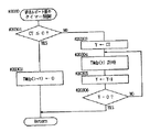
図40は図39の♯2030に示す排出レポート送信後のタイマカウント制御の処理を示すサブル―チンである。CTが0未満であるかどうかを判別する(♯20301)。ここで、CTが0未満ということは、再給紙排出レポートが出ていない、すなわち、片面プリント後の用紙が定着排出センサ231を抜ける前に図39で示した♯2031、♯2033で示す再給紙プリントコマンドを受信すると♯2035でCTの値は0未満となる。このようなときには、再給紙排出レポートが発生してからの経過時間を示すタイマ値TMdp(1〜Y)を0に設定する(♯20302)。♯20301でCTが0以上のときには、内蔵枚数CT分のタイマYを設定し(♯20303)、それぞれの用紙ごとに経過時間を経時する(♯20304)。♯20306で、すべての枚数分タイマ設定、経時開始を行なうとリターンする。なお、再給紙排出レポートがない場合はTMdp1〜TMdpYの値は0となる。
FIG. 40 is a subroutine showing processing of timer count control after transmission of the discharge report shown at # 2030 in FIG. It is determined whether or not CT is less than 0 (# 20301). Here, the fact that the CT is less than 0 means that no refeed / eject report has been issued, that is, before the paper after one-sided printing has passed through the fixing /
図41は図36の♯204に示す排出レポ―ト制御の処理を示すサブルーチンである。用紙が定着排出センサ231を抜けたことが確認されると(♯2040)、両面設定がされているかどうかを判断する(♯2041)。両面設定の場合には、プリンタコントローラ1Aに再給紙排出レポートを送信し(♯2042)、内蔵枚数を示すカウンタ値CTをインクリメントする(♯2043)。♯2040または♯2041でNOの場合には、機外排出センサ60を用紙が抜けたかどうかを判断し(♯2044)、抜けた場合には排出レポートを送信する(♯2045)。 FIG. 41 is a subroutine showing the processing of the discharge report control shown at # 204 in FIG. When it is confirmed that the sheet has passed through the fixing / discharge sensor 231 (# 2040), it is determined whether or not the both-side setting is set (# 2041). In the case of double-sided setting, a refeed / discharge report is transmitted to printer controller 1A (# 2042), and counter value CT indicating the number of built-in sheets is incremented (# 2043). In the case of NO in # 2040 or # 2041, it is determined whether or not the sheet has come out of the external ejection sensor 60 (# 2044), and if so, an ejection report is transmitted (# 2045).
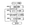
図42はプリンタコントローラ205の制御ルーチンを示すフローチャートである。まず各種の初期化が行なわれ(♯250)、ホストとの信号のやり取りを行なうホストI/F制御の処理を行なう(♯260)。印字処理部40との信号のやり取りを行なう印字処理部I/F制御の処理を行ない(♯270)、その他の処理を行なう(♯280)。
FIG. 42 is a flowchart showing a control routine of the printer controller 205. First, various initializations are performed (# 250), and processing of host I / F control for exchanging signals with the host is performed (# 260). Print processing section I / F control processing for exchanging signals with
図43は図42の♯260に示すホストI/F制御の処理を示すサブルーチンである。ホストから印字要求があると(♯2601)、両面印字要求かどうかを判断する(♯2602)。両面印字の場合には、まず片面印字を行なうためのフラグをF Simpを1にセットし(♯2603)、両面印字用のカウンタCTDupを1インクリメントさせる(♯2604)。♯2602で片面印字の場合には、FSimpを1にセットする処理のみを行なう(♯2605)。 FIG. 43 is a subroutine showing processing of host I / F control shown at # 260 in FIG. If there is a print request from the host (# 2601), it is determined whether it is a double-sided print request (# 2602). In the case of double-sided printing, first, a flag for performing single-sided printing is set to F Simp at 1 (# 2603), and the counter CTDup for double-sided printing is incremented by 1 (# 2604). In the case of single-sided printing in # 2602, only the process of setting FSimp to 1 is performed (# 2605).
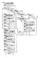
図44は図42の♯270に示す印字処理部I/F制御の処理を示すサブルーチンである。ステートカウンタSCの値を見て(♯2701)、0のときにはFSimpが1にセットされていること確認後(♯2702)、給紙口設定、片面・両面設定、プリントコマンドの各コマンドを印字処理部40に送信する処理を行なう(♯2703〜♯2705)。F Simpを0にセットし(♯706)、ステートカウンタSCを1にセットする(♯2707)。次に印字処理部40からの給紙レポートを受信するまで待つ(♯2708)。
FIG. 44 is a subroutine showing a print processing unit I / F control process indicated by # 270 in FIG. Looking at the value of the state counter SC (# 2701), when it is 0, after confirming that FSimp has been set to 1 (# 2702), print processing of each of the paper feed port setting, single-sided / double-sided setting, and print command is performed A process for transmitting to
印字処理部40からの給紙レポートが返ってくると、給紙したことを示す給紙許可レポートかどうかを見て(♯2709)、ステートカウンタSCを0にセットする(♯2716)。給紙許可レポートでないときは(♯2709でNo)、再給紙優先レポートかどうかを判断する(♯2710)。再給紙優先レポートの場合には、CT Dupを1デクリメントし(♯2712)、再給紙口設定、排出設定、プリントコマンドの各コマンドを印字処理部40に送信する(♯2713〜♯2715)。
When the paper feed report is returned from the
♯2710で給紙不可レポートのときは、ステートカウンタSCを0にセットする(♯2711)。次に再給紙プリントコマンド送信タイミング発生制御の処理を行なう(♯2717)。次いでフラグF CTupの値をチェックする(♯2718)。この値が1のときは、再給紙口設定、排出設定、プリントコマンドの各コマンドを印字処理部40に送信する(♯2719〜♯2721)。カウンタ値CT Dupを1デクリメントさせた後(♯2722)、フラグF CTupを0にリセットし(♯2723)、ステートカウンタSCを1にセットする(♯2724)。 If the report indicates that the paper cannot be fed at # 2710, the state counter SC is set to 0 (# 2711). Next, processing for generating a re-feeding print command transmission timing is performed (# 2717). Next, the value of the flag FCTup is checked (# 2718). When this value is 1, each of the re-feeding port setting, the discharge setting, and the print command is transmitted to the print processing unit 40 (# 2719 to # 2721). After decrementing the counter value CT Dup by 1 (# 2722), the flag F CTup is reset to 0 (# 2723), and the state counter SC is set to 1 (# 2724).
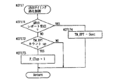
図45は図44の♯2717で示した再給紙プリントコマンド送信タイミング発生制御の内容を示すサブルーチンである。図45を参照して、ここではまず再給紙排出レポートを受信したかどうかを判断し(♯27171)、受信した場合には再給紙プリントコマンドを発生するタイミングを計る所定のタイマ値TMRPTをセットする(♯27174)。あまりに速いタイミングで再給紙プリントコマンドが発生されると、それに該当する用紙が再給紙経路61を循環して両面印字に供されるまで他の用紙は給紙できないので、可能な限り再給紙経路61に循環用紙を内蔵できるようにこのタイマ値はできるだけ長い時間にセットする。タイマ値TM RPTがカウントアップしたことが確認されると(♯27172)、フラグF CTupを1にセットする(♯27173)。
FIG. 45 is a subroutine showing the content of the refeed print command transmission timing generation control indicated by # 2717 in FIG. Referring to FIG. 45, here, it is first determined whether or not a re-feed output report has been received (# 27171). If received, a predetermined timer value TMRPT for measuring the timing of generating a re-feed print command is determined. Set (# 27174). If a refeed print command is issued at too fast a timing, another sheet cannot be fed until the corresponding sheet circulates through the
次に、図28に示したマルチジョブコントローラ208の行なう制御について説明する。CPU1より図31(B)で説明した両面印字が命令されたとき、複写機2内での用紙の搬送がどのように行なわれるかを図46をもとに説明する。
Next, control performed by the
まず、第1面をプリントすべく給紙カセットから用紙が2枚連続して給紙される(図46(A))。第1面をプリントされた用紙は第2面をプリントすべく循環経路で反転・搬送される(図46(B,C))。そして第2面がプリントされた後、次の第1面をプリントすべく給紙カセットから新しい用紙が給紙され(図46(C))、同様のことが繰返される。このとき、前記された印字処理部40から送信される給紙レポ―トや排出レポートは、マルチジョブコントローラ208へもプリンタコントローラ205から送信され、マルチジョブコントローラ208は複写機2の動作状態を知ることができる。
First, two sheets of paper are continuously fed from the paper feed cassette to print the first side (FIG. 46A). The sheet on which the first side is printed is reversed and conveyed along a circulation path to print the second side (FIGS. 46B and 46C). Then, after the second side is printed, new paper is fed from the paper feed cassette to print the next first side (FIG. 46 (C)), and the same is repeated. At this time, the paper feed report and the discharge report transmitted from the
ところで、再給紙経路長に対して第1面をプリントする用紙が少ないと(図46(B))、第1面給紙の再給紙の後端と第1面プリントされた用紙が再び画像を形成し戻ってくるまでの距離の間、何もプリントされない状態が存在する。また、たとえば、2枚4ページの両面プリントが指定されたとき、第1面の2枚目の画像がグラフィックなどが多くビットマップメモリへの展開に時間がかかってしまうと、それが終了するまで給紙ができないので給紙が遅れ、給紙の間隔が開いてしまう(図47(E))。その結果、第1面1枚目が再給紙経路261へ搬送されていても2枚目はまだ画像形成部に存在する(図47(F))。そして第2面のプリントが終わるまで給紙時に開いた間隔が保持され通紙される(図47(G),(H))。この間隔は、給紙の遅れる時間によって決まる。
By the way, if the number of sheets to be printed on the first side is small relative to the length of the re-feeding path (FIG. 46B), the trailing edge of the re-feeding of the first side and the sheet printed on the first side again There is a state in which nothing is printed during the distance from when the image is formed to when it returns. Further, for example, when two-sided and four-page double-sided printing is designated, if the second image on the first side has many graphics and the like and it takes time to develop the image in the bitmap memory, it is necessary to finish the processing. Since the paper cannot be fed, the paper feeding is delayed, and the interval between the paper feedings increases (FIG. 47E). As a result, even if the first sheet on the first side is conveyed to the
この開いたプリント間隔に、予約ジョブを行なうときには、両面プリントの第1面給紙時に、実際に給紙した間隔を覚えておき、第2のプリントを行なっている時、その隙間に予約ジョブの給紙が可能かどうかを判断する。 When performing a reserved job at this open print interval, remember the actual paper feed interval when feeding the first side of double-sided printing, and during the second print, place the reserved job in the gap. Determine whether the paper can be fed.
そこで、図48に示すように、こういった両面プリント等が行なわれているときに、別の情報処理手段からプリント命令があったり、予約ジョブがあった場合、この間でそのプリントを行なう。それを図48をもとに説明する。第1段目から2枚内蔵の両面プリントが行なわれているとき、第1面プリントのための給紙が終わったら、第2面プリントが開始されるまでの間隔を判断する。 Therefore, as shown in FIG. 48, when such a double-sided printing or the like is performed, if there is a print command from another information processing means or if there is a reserved job, the printing is performed during this time. This will be described with reference to FIG. When two sheets of built-in double-sided printing are performed from the first stage, after the sheet feeding for the first side printing is completed, an interval until the second side printing is started is determined.
その距離Pは、循環経路長(中間ローラセンサ228から定着排出センサ231までの距離+定着排出センサ231から再給紙経路261を通って中間ロ―ラセンサ28までの距離)をLjとし、最適な用紙間隔をLinvとし、第Xカセットに搭載されている用紙のサイズをPSfxとし、給紙した枚数をNfとすると次式で表わされる。
The distance P is determined by the length of the circulation path (the distance from the
P=Lj−PSfx×Nf−Linv×(Nf−1)また、割込ませる予約ジョブが第Y段目に入っている用紙を使うとすると、第Yカセットに搭載されている用紙のサイズPSfyとすると、この距離Pが、P>PSfy+Linv×2を満たすとき、第Yカセットからの給紙が可能となる。 P = Lj−PSfx × Nf−Linv × (Nf−1) Also, assuming that the reserved job to be interrupted uses paper in the Y-th stage, the size PSfy of the paper loaded in the Y-th cassette and Then, when the distance P satisfies P> PSfy + Linv × 2, paper can be fed from the Y-th cassette.
図48では、予約ジョブは第2段目から給紙を行なうとする(図48(A))。この場合、第2段目から2枚給紙を行なっている。第2段目から給紙された用紙は先行ジョブの排出トレイとは異なるトレイに排出され、第1段目から給紙された用紙は第2面のプリントを行なうべく再給紙経路261を通って画像形成部へ再給紙される(図48(B))。第2面をプリントされた用紙は機外へ排出されて再び第1面のプリントをするため第1段目から給紙が行なわれる(図48(C))。第1面プリントのための給紙が終わったら、さらに他の予約ジョブが第3段目に入っている用紙を使うとすると、第3段目から給紙を行なう(図48(D))。
In FIG. 48, it is assumed that a reserved job is fed from the second stage (FIG. 48A). In this case, two sheets are fed from the second stage. The paper fed from the second tier is discharged to a tray different from the discharge tray of the preceding job, and the paper fed from the first tier passes through the
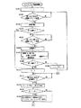
図49は、マルチジョブコントローラ208の制御ルーチンを示すフローチャートである。図49を参照して、♯90では、ページプリンタPRTが両面プリント中に他の情報処理手段からの予約ジョブが実行できるかを判断し、実行可能な場合は給紙命令を出力する。♯100では、ページプリンタPRTが両面プリント中に他の情報処理手段からの予約ジョブが実行されたら、それに合わせてバッファメモリからそのジョブの画像データを呼出し、ページプリンタPRTへ出力する。
FIG. 49 is a flowchart showing a control routine of the
図50は図49の♯90に示すマルチジョブ給紙制御のサブルーチンを示すフローチャートである。両面プリントの第1面の給紙かすべて終了したら(♯901)、他の情報処理手段からの予約ジョブがないか判断する(♯902)。予約ジョブがあったら、第1面最終紙の後ろへ他の予約ジョブの用紙が給紙できないかを判断するために前記距離Pを計算する(♯903)。また、予約ジョブが要求する用紙が第Y段目に入っているとして、そのY段目に入っている用紙を給紙できるか前記距離Qを計算する(♯904)。PとQを比較し(♯905)、P≧Qなら給紙が可能なので、第Y段目からの給紙をプリンタコントローラ205へ命令する(♯906)。そして給紙枚数Nfをインクリメントし(♯907)、さらに給紙可能かどうかを見に行くため、♯902へ戻す。このサブルーチンの制御がすべて終了したら、第2面のプリントを行なうためリターンする。 FIG. 50 is a flowchart showing a subroutine of the multi-job paper feed control shown at # 90 in FIG. When the first side of double-sided printing is completely fed (# 901), it is determined whether there is a reserved job from another information processing means (# 902). If there is a reserved job, the distance P is calculated to determine whether sheets of another reserved job cannot be fed behind the last sheet of the first side (# 903). Also, assuming that the sheet requested by the reserved job is in the Y-th stage, the distance Q is calculated as to whether the sheet in the Y-stage can be fed (# 904). P and Q are compared (# 905), and if P≥Q, paper feeding is possible, and a command to feed paper from the Y-th stage to the printer controller 205 (# 906). Then, the number Nf of fed sheets is incremented (# 907), and the process returns to # 902 to check whether or not the sheet can be fed further. When the control of this subroutine is completed, the process returns to print the second surface.
図51は図49の♯100に示すマルチジョブメモリ読出制御のサブルーチンを示すフローチャートである。両面プリントの第1面の給紙がすべて終了したら(♯1001)、他の情報処理手段からの予約ジョブがないか判断する(♯1002)。予約ジョブが受付けられ第Y段目からの給紙が実行されたら(♯1003)、バッファメモリに記憶されている予約ジョブの画像データを読出す(♯1004)。そして読出したデータをビットマップメモリに展開しページプリンタPRTへ送信する(♯1005)。場合によっては、第Y段目からの給紙が続けられているときもあるので、第Y段目からの給紙が終了したかをチェックする(♯1006)。終了していなければ再び予約ジョブの画像データを読出すため♯1004に戻す。このサブルーチンの制御がすべて終了したら第2面のプリントを行なうためリターンする。 FIG. 51 is a flowchart showing a subroutine of the multi-job memory read control shown at # 100 in FIG. When the first side of the double-sided printing is completely fed (# 1001), it is determined whether there is a reserved job from another information processing means (# 1002). When the reserved job is received and the sheet feeding from the Y-th stage is executed (# 1003), the image data of the reserved job stored in the buffer memory is read (# 1004). Then, the read data is developed in the bit map memory and transmitted to the page printer PRT (# 1005). In some cases, the sheet feeding from the Y-th stage may be continued, so it is checked whether the sheet feeding from the Y-th stage has been completed (# 1006). If not completed, the process returns to $ 1004 to read the image data of the reserved job again. When the control of this subroutine is completed, the process returns to print the second surface.
次にさらに他の実施形態について説明する。さらに他の実施形態においては、マルチジョブコントローラ208の行なう制御について図52および図53を参照して説明する。
Next, still another embodiment will be described. In still another embodiment, control performed by
2枚4ページの両面プリントが指定されたとき、第1面の2枚目の画像がグラフィックなどが多くビットマップメモリへの展開に時間がかかっしまうと、それが終了するまで給紙ができない。そのため、給紙の間隔があいてしまう(図52(A))。その結果、1面1枚目が再給紙経路へ搬送されていても2枚目はまだ画像形成部にある(図52(B))。 When two-sided and four-page double-sided printing is designated, if the second image on the first side has many graphics and the like and takes a long time to develop in the bitmap memory, paper feeding cannot be performed until the processing is completed. For this reason, there is an interval between sheet feeding (FIG. 52A). As a result, even if the first sheet on the first side is conveyed to the re-feeding path, the second sheet is still in the image forming unit (FIG. 52B).
そこで、1枚目の給紙が終了してから2枚目の給紙が開始されるまでの間隔を計数し記憶する。1枚目、2枚目の給紙タイミングは、印字処理部から送信される給紙レポートにより知ることができる。そして、その間隔Rは、R=(1枚目・2枚目給紙レポートの時間間隔)/搬送速度−用紙サイズで表わされる。 Therefore, the interval from the end of the first sheet feeding to the start of the second sheet feeding is counted and stored. The feed timing of the first and second sheets can be known from a feed report transmitted from the print processing unit. The interval R is represented by R = (time interval of first / second sheet feed report) / conveyance speed−sheet size.
また、割込ませる予約ジョブが第Y段目に入っている用紙を使うとし、第Yカセットに搭載されている用紙のサイズPSfy、最適な用紙間隔Linvとすると、この距離Rが、R>PSfy+Linv×2
を満たすとき、第Yカセットからの給紙が可能になる。
Also, assuming that the reserved job to be interrupted uses paper in the Y-th stage, and that the size of paper loaded in the Y-th cassette is PSfy and the optimal paper interval is Linv, this distance R is R> PSfy + Linv. × 2
When the condition is satisfied, the sheet can be fed from the Yth cassette.
図52では、予約ジョブが第2段目から給紙を行なうとする。再給紙経路から戻ってきた第2面1枚目の用紙の後ろへ、予約ジョブの用紙を第2段目から給紙する(図52(C))。第2面1枚目の用紙は第2面を印字終了後機外へ排出され、予約ジョブの用紙に画像がプリントされる(図52(D))。予約ジョブの用紙は、先行ジョブとは別の排出トレイへ排出され、先行ジョブの次の給紙が行なわれる(図53(E))。 In FIG. 52, it is assumed that the reserved job feeds paper from the second stage. The sheet of the reserved job is fed from the second stage behind the first sheet on the second side returned from the refeeding path (FIG. 52 (C)). The first sheet of the second side is discharged to the outside after the printing of the second side is completed, and the image is printed on the sheet of the reserved job (FIG. 52 (D)). The sheet of the reserved job is discharged to a discharge tray different from that of the preceding job, and the next sheet feeding of the preceding job is performed (FIG. 53 (E)).
このときのマルチジョブコントローラ208のマルチジョブ給紙制御は、図54および図55で示される。2枚4ページの両面プリントのとき、第1面の1枚目の画像がグラフィックなどが多くビットマップメモリへの展開に時間がかかった場合をもとに説明する。
The multi-job feed control of the
i=1と初期設定(♯1101)した後、第1面1枚目の給紙レポートの受信を待つ(♯1102)。第1面1枚目の給紙レポートを受信したら、給紙間隔の時間の計数を開始する(♯1103)。まだ第1面を終了していないので、第1面2枚目の給紙レポートの受信を待つ(♯1104,♯1105)。第1面2枚目の給紙レポートの受信をしたら、給紙間隔の時間の計数を終了し(♯1106)、給紙間隔R1を計算する(♯1107)。第1面が終了したので(♯1108)、j=1と初期設定した後(♯1110)、第2面1枚目の給紙が終了するのを待つ(♯1111)。第2面1枚目の給紙が終了したら、割込ませる予約ジョブが第Y段目に入っている用紙を使うとして、その用紙を第2面1枚目と第2面2枚目との間に割込給紙するのに必要な間隔S1を計算する(♯1112)。Kは割込ませる枚数で自然数である。その結果、K=1でR1>S1が成立したら、第Y段目から1枚の給紙をプリンタコントローラ205へ命令し(♯1114)、その割込んだ予約ジョブの給紙終了を待つ(♯1115)。次の処理(♯1116)でj=2となり、j=i=2となってi,jをともに0にクリアしてリターンする(♯1117,♯1118)。 After the initial setting of i = 1 (# 1101), the process waits for reception of the first sheet feed report (# 1102). When the first-side first sheet feed report is received, counting of the sheet feed interval time is started (# 1103). Since the first side has not been completed, the reception of the paper feed report for the second side of the first side is waited (# 1104, # 1105). When the paper feed report for the second sheet on the first side is received, the counting of the paper feed interval is terminated (# 1106), and the paper feed interval R1 is calculated (# 1107). Since the first side has been completed (# 1108), after the initial setting of j = 1 (# 1110), the process waits for the end of sheet feeding of the first side of the second side (# 1111). When the first sheet of the second side is completed, it is assumed that the reserved job to be interrupted uses the sheet included in the Y-th stage, and the sheet is switched between the first sheet of the second side and the second sheet of the second side. An interval S1 required for intermittent sheet feeding is calculated (# 1112). K is the number of interrupts and is a natural number. As a result, if R1> S1 is satisfied with K = 1, a command is issued to the printer controller 205 to feed one sheet from the Y-th stage (# 1114), and the feed of the interrupted reserved job is waited for (# 1114). 1115). In the next process (# 1116), j = 2, j = i = 2, i and j are both cleared to 0, and the process returns (# 1117, # 1118).
ところで、3枚以上の内蔵枚数の両面プリントのときには、♯1108にて第1面を終了していないので、iをインクリメントして♯1102に戻す。2枚目と3枚目の間の間隔R、3枚目と4枚目の間の間隔R3、…を繰返し求める。また、♯1117で第2面のプリントが終了するまで♯1111へ処理をもどし、割込給紙するのに必要な間隔S2,S3,…を求めて第2面プリント中に用紙間に割込が可能かを判断する。 By the way, in the case of three or more built-in double-sided printing, since the first surface is not completed at # 1108, i is incremented and returned to # 1102. An interval R between the second and third sheets, an interval R3 between the third and fourth sheets,... Are repeatedly obtained. Also, the process returns to # 1111 until the printing of the second side is completed at # 1117, and the intervals S2, S3,. Judge whether it is possible.
次に、マルチジョブコントローラ208のマルチジョブメモリ読出制御を図56を参照して説明する。上記マルチジョブ給紙制御と同じく、2枚4ページの両面プリントのとき、第1面の2枚目の画像がグラフィックなどが多く、ビットマップメモリへの展開に時間がかかった場合をもとに説明する。
Next, the multi-job memory read control of the
I=1と初期設定した後(♯1201)、第2面のI枚目のプリント終了を待つ(♯1202)。この予約ジョブがあったときその予約ジョブの給紙命令が出ているかをチェックする(♯1203,♯1204)。予約ジョブの給紙命令が出ていたら、その予約ジョブの画像データをバッファメモリから読出し(♯1205)、読出したデータをビットマップメモリに展開し複写機へ送信する(♯1206)。その予約ジョブの給紙がすべて終了したら(♯1207)、Iをインクリメントして(♯1208)、I=2になったのでIを0クリアして(♯1209,♯1210)、リターンする。 After the initial setting of I = 1 (# 1201), the process waits for the completion of the printing of the I-th sheet on the second side (# 1202). When there is this reserved job, it is checked whether a feed command for the reserved job has been issued (# 1203, # 1204). If a paper feed command for the reserved job has been issued, the image data of the reserved job is read from the buffer memory (# 1205), and the read data is developed in the bit map memory and transmitted to the copying machine (# 1206). When all the paper feeds for the reserved job are completed (# 1207), I is incremented (# 1208), and since I = 2, I is cleared to 0 (# 1209, # 1210), and the routine returns.
ところで、3枚以上の内蔵枚数の両面プリントのときには、♯1209で第2面を給紙した枚数が第1面給紙した枚数に等しくなるまで♯1202に戻され、他の予約ジョブの画像の読出しをするかが再びチェックされる。 In the case of three or more built-in double-sided prints, the number of sheets fed on the second side is returned to # 1202 until the number of sheets fed on the first side becomes equal to the number of sheets fed on the first side in # 1209. It is checked again whether to read.
ここまで、両面プリントで用紙間隔がひらいたときに、予約ジョブを割込実行させる例を述べてきたが、両面プリント以外で用紙間隔がひらく場合についても同様に適用できる。そのような場合としては次のようなものがある。 Up to this point, an example has been described in which the reserved job is interrupted when the paper interval is opened in double-sided printing. However, the present invention can be similarly applied to a case where the paper interval is opened other than in double-sided printing. Such cases include the following.
フィニッシャ、ステープルソーターなどでステープルを行ないながらコピーをする場合、まず用紙をステープル位置へ揃えながら収納して収納後ステープルを行なって機械へ排出する。このステープルを行なう際、次の用紙の収納ができないので、用紙間隔をあけておく必要がある。このとき、予約ジョブにステープルをする必要がないものがあれば先の実施例の図26,27に示したように割込実行が可能になる。 When performing copying while stapling with a finisher, staple sorter, or the like, first store the paper while aligning it at the staple position, and then stapling and discharging to the machine. When this stapling is performed, the next sheet cannot be stored, so it is necessary to keep a space between sheets. At this time, if there is a reserved job that does not need to be stapled, the interruption can be executed as shown in FIGS.
1,2 複写機10 走査系16 イメージセンサ
19 スキャナ
20 画像信号処理部
21 A/D変換部
22 画像処理部
23 画像モニタ用メモリ
24 タイミング制御部
30 メモリユニット部
40 印字処理部
50 FAXコントローラ
60 プリントヘッド
62 半導体レーザ
70A 現像・転写系
70B 定着・排出系
70C 用紙搬送系
71 感光体ドラム
73 現像器
75 転写チャージャ
80a,80b 用紙カセット
84 定着ローラ対
85 排出ローラ
91 タッチパネル
92 テンキー
97 原稿指定キー
99 バインドモード選択キー
100 制御部
205 プリンタコントローラ
208 マルチジョブコントローラ
261 再給紙経路
301 バス切換部
302 2値化処理部
304 画像メモリ
305 符号処理部
306 符号メモリ
308 回転処理部
309 多値化処理部
500 自動原稿送り装置
510 原稿スタッカ
511 原稿排出トレイ
600 再給紙ユニット
601,604 切換爪
621 排紙トレイ
625 再給紙部
631 バインド部
636 バインド排出トレイ
IR イメージリーダ
PRT ページプリンタ
1, 2
Claims (1)
前記各ジョブに対応する入力画像データを印字のために予めメモリに展開する手段と、
前記展開された画像データを用紙上に印字する印字手段と、
先行ジョブの実行中にその用紙の間隔を検出する手段と、
前記検出された用紙間隔内に割込ジョブの実行が可能か否かを判断する手段と、
前記判断手段が前記割込ジョブの実行が可能であると判断したときは、前記割込ジョブを前記先行ジョブと同時に実行する手段とを含む、画像処理装置。
An image processing apparatus capable of interrupting another job during execution of a normal job,
Means for expanding input image data corresponding to each job in a memory in advance for printing,
Printing means for printing the developed image data on paper,
Means for detecting the paper interval during execution of the preceding job;
Means for determining whether an interrupt job can be executed within the detected paper interval,
Means for executing the interrupt job simultaneously with the preceding job when the determining means determines that the interrupt job can be executed.
Priority Applications (1)
| Application Number | Priority Date | Filing Date | Title |
|---|---|---|---|
| JP2003405940A JP3791522B2 (en) | 2003-12-04 | 2003-12-04 | Image processing device |
Applications Claiming Priority (1)
| Application Number | Priority Date | Filing Date | Title |
|---|---|---|---|
| JP2003405940A JP3791522B2 (en) | 2003-12-04 | 2003-12-04 | Image processing device |
Related Parent Applications (1)
| Application Number | Title | Priority Date | Filing Date |
|---|---|---|---|
| JP7325979A Division JPH09163067A (en) | 1995-12-14 | 1995-12-14 | Image processor |
Publications (2)
| Publication Number | Publication Date |
|---|---|
| JP2004173291A true JP2004173291A (en) | 2004-06-17 |
| JP3791522B2 JP3791522B2 (en) | 2006-06-28 |
Family
ID=32709330
Family Applications (1)
| Application Number | Title | Priority Date | Filing Date |
|---|---|---|---|
| JP2003405940A Expired - Lifetime JP3791522B2 (en) | 2003-12-04 | 2003-12-04 | Image processing device |
Country Status (1)
| Country | Link |
|---|---|
| JP (1) | JP3791522B2 (en) |
Cited By (3)
| Publication number | Priority date | Publication date | Assignee | Title |
|---|---|---|---|---|
| EP1752834A3 (en) * | 2005-08-11 | 2008-05-28 | Konica Minolta Business Technologies, Inc. | Image forming system and image forming apparatus |
| US7609395B2 (en) | 2005-02-17 | 2009-10-27 | Sharp Kabushiki Kaisha | Image forming apparatus |
| JP2012088501A (en) * | 2010-10-19 | 2012-05-10 | Ricoh Co Ltd | Image forming apparatus |
-
2003
- 2003-12-04 JP JP2003405940A patent/JP3791522B2/en not_active Expired - Lifetime
Cited By (4)
| Publication number | Priority date | Publication date | Assignee | Title |
|---|---|---|---|---|
| US7609395B2 (en) | 2005-02-17 | 2009-10-27 | Sharp Kabushiki Kaisha | Image forming apparatus |
| EP1752834A3 (en) * | 2005-08-11 | 2008-05-28 | Konica Minolta Business Technologies, Inc. | Image forming system and image forming apparatus |
| US7522855B2 (en) | 2005-08-11 | 2009-04-21 | Konica Minolta Business Technologies, Inc. | Image forming system and image forming apparatus |
| JP2012088501A (en) * | 2010-10-19 | 2012-05-10 | Ricoh Co Ltd | Image forming apparatus |
Also Published As
| Publication number | Publication date |
|---|---|
| JP3791522B2 (en) | 2006-06-28 |
Similar Documents
| Publication | Publication Date | Title |
|---|---|---|
| US5740497A (en) | Image processing apparatus that can execute interruption job efficiently | |
| JPH0686030A (en) | Copying machine | |
| JP3279160B2 (en) | Copiers and page printers | |
| JPH10136143A (en) | Image processing system | |
| JP3938844B2 (en) | Image forming system | |
| US5983051A (en) | Image formation apparatus executing plurality registered jobs in order | |
| JP3791522B2 (en) | Image processing device | |
| JP3277672B2 (en) | Digital copier | |
| JPH11138956A (en) | Image-forming device | |
| JP2000047536A (en) | Coupling method of copier network system | |
| JP3353625B2 (en) | Image forming device | |
| JPH066541A (en) | Copying machine | |
| JP3562329B2 (en) | Image forming device | |
| JP3530874B2 (en) | Image forming device | |
| JPH11289436A (en) | Image forming device | |
| JP3550494B2 (en) | Image forming device | |
| JP2002252733A (en) | Network system for image forming apparatus | |
| JP3666197B2 (en) | Image forming apparatus | |
| JP3716085B2 (en) | Image forming apparatus | |
| JP2002142050A (en) | Image forming system | |
| JP2000022876A (en) | Network system for image forming device | |
| JPH09149165A (en) | Image forming device | |
| JPH11284780A (en) | Image forming device | |
| JPH10153928A (en) | Copier network system | |
| JPH11125995A (en) | Image forming device |
Legal Events
| Date | Code | Title | Description |
|---|---|---|---|
| A977 | Report on retrieval |
Free format text: JAPANESE INTERMEDIATE CODE: A971007 Effective date: 20050615 |
|
| A131 | Notification of reasons for refusal |
Free format text: JAPANESE INTERMEDIATE CODE: A131 Effective date: 20050705 |
|
| A521 | Written amendment |
Free format text: JAPANESE INTERMEDIATE CODE: A523 Effective date: 20050902 |
|
| TRDD | Decision of grant or rejection written | ||
| A01 | Written decision to grant a patent or to grant a registration (utility model) |
Free format text: JAPANESE INTERMEDIATE CODE: A01 Effective date: 20060314 |
|
| A61 | First payment of annual fees (during grant procedure) |
Free format text: JAPANESE INTERMEDIATE CODE: A61 Effective date: 20060327 |
|
| R150 | Certificate of patent or registration of utility model |
Free format text: JAPANESE INTERMEDIATE CODE: R150 |
|
| FPAY | Renewal fee payment (event date is renewal date of database) |
Free format text: PAYMENT UNTIL: 20090414 Year of fee payment: 3 |
|
| FPAY | Renewal fee payment (event date is renewal date of database) |
Free format text: PAYMENT UNTIL: 20100414 Year of fee payment: 4 |
|
| FPAY | Renewal fee payment (event date is renewal date of database) |
Free format text: PAYMENT UNTIL: 20110414 Year of fee payment: 5 |
|
| FPAY | Renewal fee payment (event date is renewal date of database) |
Free format text: PAYMENT UNTIL: 20120414 Year of fee payment: 6 |
|
| FPAY | Renewal fee payment (event date is renewal date of database) |
Free format text: PAYMENT UNTIL: 20130414 Year of fee payment: 7 |
|
| FPAY | Renewal fee payment (event date is renewal date of database) |
Free format text: PAYMENT UNTIL: 20140414 Year of fee payment: 8 |
|
| S111 | Request for change of ownership or part of ownership |
Free format text: JAPANESE INTERMEDIATE CODE: R313111 |
|
| R350 | Written notification of registration of transfer |
Free format text: JAPANESE INTERMEDIATE CODE: R350 |
|
| EXPY | Cancellation because of completion of term |